EP1795976A2 - Timepiece - Google Patents
Timepiece Download PDFInfo
- Publication number
- EP1795976A2 EP1795976A2 EP06022987A EP06022987A EP1795976A2 EP 1795976 A2 EP1795976 A2 EP 1795976A2 EP 06022987 A EP06022987 A EP 06022987A EP 06022987 A EP06022987 A EP 06022987A EP 1795976 A2 EP1795976 A2 EP 1795976A2
- Authority
- EP
- European Patent Office
- Prior art keywords
- wheel
- stop wheel
- clock according
- axis
- radially
- Prior art date
- Legal status (The legal status is an assumption and is not a legal conclusion. Google has not performed a legal analysis and makes no representation as to the accuracy of the status listed.)
- Granted
Links
- 230000000737 periodic effect Effects 0.000 claims abstract description 4
- 210000000078 claw Anatomy 0.000 claims description 11
- 230000005540 biological transmission Effects 0.000 claims description 5
- 239000011248 coating agent Substances 0.000 claims description 2
- 238000000576 coating method Methods 0.000 claims description 2
- 238000013016 damping Methods 0.000 description 1
- 230000006870 function Effects 0.000 description 1
- 230000010355 oscillation Effects 0.000 description 1
- 238000004091 panning Methods 0.000 description 1
Images


Classifications
-
- G—PHYSICS
- G04—HOROLOGY
- G04B—MECHANICALLY-DRIVEN CLOCKS OR WATCHES; MECHANICAL PARTS OF CLOCKS OR WATCHES IN GENERAL; TIME PIECES USING THE POSITION OF THE SUN, MOON OR STARS
- G04B1/00—Driving mechanisms
- G04B1/10—Driving mechanisms with mainspring
- G04B1/22—Compensation of changes in the motive power of the mainspring
- G04B1/225—Compensation of changes in the motive power of the mainspring with the aid of an interposed power-accumulator (secondary spring) which is always tensioned
-
- G—PHYSICS
- G04—HOROLOGY
- G04B—MECHANICALLY-DRIVEN CLOCKS OR WATCHES; MECHANICAL PARTS OF CLOCKS OR WATCHES IN GENERAL; TIME PIECES USING THE POSITION OF THE SUN, MOON OR STARS
- G04B15/00—Escapements
- G04B15/10—Escapements with constant impulses for the regulating mechanism
Definitions
- the invention relates to a watch, in particular a wristwatch with a constant force device for acting on a vibrating system, with a switching unit of the constant force device for periodically controlled tensioning of the secondary spring memory of a clamping module of the constant force device by a spring drum forming a primary spring memory, wherein the periodic control of the switching unit is effected by means of a cam , which is permanently rotatable drivable.
- the output of the primary spring memory must be designed high.
- the object of the invention is therefore to provide a clock of the type mentioned, in which with little effort, a high torque on the cam is effective.
- the switching unit preferably has one of the barrel, in particular via a Kleinêtrad about a Stoppradachse rotatably driven Stop wheel, which has one or more radial teeth into which a pallet of a rocker pivotable about an axis parallel to the stop wheel axis rocking a rotational movement of the stop wheel is radially engageable, with a claw of the rocker, which surrounds the one or more radially projecting cams cam plate and is periodically pivotable by the rotational movement of the cam disc, whereby the pallet is disengaged from the radial tooth can be brought.
- a largely direct power transfer from the barrel to the secondary spring accumulator is achieved in a simple and space-saving manner, when the barrel, in particular via a Kleinêtrad a second shaft coaxial intermediate tube is rotatably driven, having a drive wheel for rotatably driving the stop wheel and a holding plate connected to the Sekundärfeder letters ,
- the intermediate tube can surround the second shaft coaxially.
- the secondary spring accumulator is a coil spring which coaxially surrounds the second shaft and is fixed with its radially inner end to the second shaft and with its radially outer end to the retaining plate.
- the holding plate can carry a spiral stud, to which the radially outer end of the spiral spring is fastened.
- an escape wheel of the vibration system can be rotatably driven.
- the second wave carries a second hand.
- the rocker is pivotally mounted with its one end portion about the swing axis, has at its other end the claw and encloses the stop wheel radially with its central region, wherein at the central region one or more radially projecting to the stop wheel pallets are arranged by panning the rocker are radially movable in the orbit of the tooth or the teeth of the stop wheel.
- the claw may have a friction-reducing coating on its surfaces acted upon by the cams of the cam disk.
- the stop wheel axis preferably cuts a straight line between the second shaft axis and the oscillation axis.
- a large swing path of the pallets is achieved when the distance between the stop wheel axis and the swing axis is greater than the distance between the stop wheel axis and the seconds shaft axis.
- an air vortex brake in a simple wear-free manner of the leading to the stop wheel drive train an air vortex brake can be driven, which may have a rotatably drivable brake axle having radially directed brake vanes.
- the Kleingeberrad 2 fixedly mounted on the Kleinêtradwelle 1 is engaged with a transmission wheel 3, which is fixedly mounted on a 10-second tube 4.
- the stop wheel 8 At its radially circumferential lateral surface, the stop wheel 8 has a radially protruding tooth 10.
- rocker 11 In the same plane as the stop wheel 8 is a rocker 11 which is pivotable about a parallel to the axis of rotation of the stop wheel shaft 7 swing axle 12.
- the rocker 11 is the stop wheel 8 formed encompassing with radial distance and has approximately diametrically opposite two pallets 13, which protrude radially to the stop wheel 8 out.
- the distance between the two pallets 13 to each other is such that one of the pallets 13 protrudes radially into the orbit of the tooth 10 and 10 blocks on rotation of the stop wheel 8 when the tooth 10 on this pallet, while the other of the pallets 13 outside the orbit of the tooth 10 is located.
- the rocker 11 On the opposite side of the oscillating axis 12 of the stop wheel 8, the rocker 11 has a fork-shaped claw 14. This claw 14 engages with its claw arms 15, a cam 16 with three radially projecting cam 17th
- the cam 16 is fixedly mounted on the one end of a second shaft 18 which extends coaxially through the 10-second tube 4 and carries a second hand 19 at its other free end.
- a holding plate 20 of a clamping module 27 is fixed on this, which carries at its radially outer region an axially projecting spiral stud 21 which protrudes axially to the side of the cam 16.
- the outer end of a helical spring 22 spaced around the seconds shaft 18 is fixed, while the inner end of the spiral spring 22 is fixed to the second hand 19 via a holding part 23.
- the second shaft 18 carries a second wheel 24, through which the rotational movement of the second wave 18 is transferred to a arranged on an armature shaft 25 anchor pinion 26.
- a brake intermediate wheel 34 is further arranged, which engages in a pinion 35 of an air vortex brake 37, which sits on a brake axle 36.
- radially directed brake vanes 38 are arranged on the brake axle.
- the function of the device is as follows: From the spring, not shown, the 10-second tube 4 is acted upon by the small-bottom wheel 2 with a rotational tension.
- one of the pallets 13 engages behind the tooth 10 of the stop wheel 8 and thus blocks it.
- the tensioned coil spring 22 drives the oscillating system 29 via the second shaft 18 and rotates the cam disk 16 at one revolution per minute.
- the cams 17 of the cam disc 16 are in abutment against the jaw arms 15 of the claw 14 of the rocker 11 and deflect it in a pivoting direction in which the one pallet 13 is moved more and more in disengagement of the tooth 10 until the tooth 10 of the pallet is completely released.
- stop wheel 8 is rotated until the tooth 10 after 180 ° rotation comes to rest on the other pallet 13, by pivoting the Rocker 11 has entered the orbit of the tooth 10. Now the device is back in normal position.
Abstract
Description
Die Erfindung bezieht sich auf eine Uhr, insbesondere Armbanduhr mit einer Konstantkraftvorrichtung zur Beaufschlagung eines Schwingsystems, mit einer Schalteinheit der Konstantkraftvorrichtung zum periodisch gesteuerten Spannen des Sekundärfederspeichers eines Spannmoduls der Konstantkraftvorrichtung durch ein einen Primärfederspeicher bildendes Federhaus, wobei die periodische Steuerung der Schalteinheit mittels einer Nockenscheibe erfolgt, die permanent drehbar antreibbar ist.The invention relates to a watch, in particular a wristwatch with a constant force device for acting on a vibrating system, with a switching unit of the constant force device for periodically controlled tensioning of the secondary spring memory of a clamping module of the constant force device by a spring drum forming a primary spring memory, wherein the periodic control of the switching unit is effected by means of a cam , which is permanently rotatable drivable.
Durch derartige Konstantkraftvorrichtungen erfolgt keine direkte Beaufschlagung des Schwingsystems durch den Primärfederspeicher sondern ein periodisches Spannen des Sekundärfederspeichers, der dann das Schwingsystem beaufschlagt.By such Konstantkraftvorrichtungen there is no direct action on the vibrating system by the primary spring memory but a periodic clamping of the secondary spring accumulator, which then acts on the vibrating system.
Damit ist das das Schwingsystem beaufschlagende Kraftniveau weitesgehend konstant, was zu einer hohen Ganggenauigkeit der Uhr führt.Thus, the force acting on the oscillating system force level is largely constant, resulting in a high accuracy of the clock.
Bei einer bekannten Uhr mit einer Konstantkraftvorrichtung besteht das Problem eines großen Kraftverlustes auf dem Übertragungsweg von dem Primärfederspeicher zum Sekundärfederspeicher, der auch die Nockenscheibe antreibt, so daß das an der Nockenscheibe wirkende Drehmoment relativ gering ist.In a known clock with a constant force device, there is the problem of a large loss of power on the transmission path from the Primärfederspeicher to the secondary spring memory, which is also the cam drives, so that the torque acting on the cam is relatively small.
Um ein ausreichendes Drehmoment zu erhalten, muß daher die Ausgangskraft des Primärfederspeichers hoch ausgelegt sein.In order to obtain a sufficient torque, therefore, the output of the primary spring memory must be designed high.
Aufgabe der Erfindung ist es daher eine Uhr der eingangs genannten Art zu schaffen, bei der mit geringem Aufwand ein hohes Drehmoment an der Nockenscheibe wirksam ist.The object of the invention is therefore to provide a clock of the type mentioned, in which with little effort, a high torque on the cam is effective.
Diese Aufgabe wird erfindungsgemäß dadurch gelöst, daß von dem Sekundärfederspeicher eine Sekundenwelle drehbar antreibbar ist, die die Nockenscheibe und ein das Schwingsystem antreibendes Sekundenrad trägt.This object is achieved in that of the Sekundärfederspeicher a second shaft is rotatably driven, which carries the cam and a driving the oscillating system seconds.
Durch diese Ausbildung erfolgt ein weitgehend direkter Krafttransfer von dem Primärfederspeicher auf den Sekundärfederspeicher, so daß an der Nockenscheibe ein hohes Drehmoment wirksam ist. Dieses sorgt für ein zuverlässiges Schalten der Schalteinheit.As a result of this design, a largely direct transfer of force from the primary spring accumulator to the secondary spring accumulator takes place, so that a high torque is active on the cam disc. This ensures reliable switching of the switching unit.
Die Schalteinheit weist vorzugsweise ein von dem Federhaus insbesondere über ein Kleinbodenrad um eine Stoppradachse drehbar antreibbares Stopprad auf, das einen oder mehrere radiale Zähne besitzt, in die eine Palette einer um eine zur Stoppradachse parallele Schwingachse schwenkbaren Schwinge eine Drehbewegung des Stopprades sperrend radial eingreifbar ist, mit einer Klaue der Schwinge, die die ein oder mehrere radial hervorstehende Nocken aufweisende Nockenscheibe umgreift und durch die Drehbewegung der Nockenscheibe periodisch schwenkbar ist, wodurch die Palette außer Eingriff von dem radialen Zahn bringbar ist.The switching unit preferably has one of the barrel, in particular via a Kleinbodenrad about a Stoppradachse rotatably driven Stop wheel, which has one or more radial teeth into which a pallet of a rocker pivotable about an axis parallel to the stop wheel axis rocking a rotational movement of the stop wheel is radially engageable, with a claw of the rocker, which surrounds the one or more radially projecting cams cam plate and is periodically pivotable by the rotational movement of the cam disc, whereby the pallet is disengaged from the radial tooth can be brought.
Ein weitgehend direkter Krafttransfer von dem Federhaus zum Sekundärfederspeicher wird auf einfache und bauraumsparende Weise erreicht, wenn von dem Federhaus insbesondere über ein Kleinbodenrad ein zur Sekundenwelle koaxiales Zwischenrohr drehbar antreibbar ist, das ein Antriebsrad zum drehbaren Antrieb des Stopprades und eine mit dem Sekundärfederspeicher verbundene Halteplatte aufweist.A largely direct power transfer from the barrel to the secondary spring accumulator is achieved in a simple and space-saving manner, when the barrel, in particular via a Kleinbodenrad a second shaft coaxial intermediate tube is rotatably driven, having a drive wheel for rotatably driving the stop wheel and a holding plate connected to the Sekundärfederspeicher ,
Treibt das Antriebsrad über ein Übersetzungsgetriebe das Stopprad drehbar an, so führt dies zu einer relativ geringen Kraftbeaufschlagung der Palette der Schwinge durch den Zahn des Stopprades, so daß sich bei der Relativbewegung zwischen Zahn und Palette nur geringe Reibkräfte ergeben, die bei der Schwenkbewegung der Schwinge durch die Nockenscheibe zu überwinden sind.If the drive wheel rotatably drives the stop wheel via a transmission gear, this results in a relatively small application of force to the pallet of the rocker by the tooth of the stop wheel, so that only slight frictional forces result during the relative movement between the tooth and the pallet to be overcome by the cam.
Zur Bauraumreduzierung kann das Zwischenrohr die Sekundenwelle koaxial umschließen.To reduce the space, the intermediate tube can surround the second shaft coaxially.
Ebenfalls zu einem kompakten Aufbau führt es, wenn der Sekundärfederspeicher eine Spiralfeder ist, die koaxial die Sekundenwelle umschließt und mit ihrem radial inneren Ende an der Sekundenwelle sowie mit ihrem radial äußeren Ende an der Halteplatte befestigt ist.It also leads to a compact design, when the secondary spring accumulator is a coil spring which coaxially surrounds the second shaft and is fixed with its radially inner end to the second shaft and with its radially outer end to the retaining plate.
Dazu kann die Halteplatte ein Spiralklötzchen tragen, an dem das radial äußere Ende der Spiralfeder befestigt ist.For this purpose, the holding plate can carry a spiral stud, to which the radially outer end of the spiral spring is fastened.
Von dem Sekundenrad kann ein Ankerrad des Schwingsystems drehbar antreibbar sein.From the second wheel, an escape wheel of the vibration system can be rotatably driven.
Die Sekundenwelle trägt einen Sekundenzeiger.The second wave carries a second hand.
Vorzugsweise ist die Schwinge mit ihrem einen Endbereich um die Schwingachse schwenkbar gelagert, weist an ihrem anderen Endbereich die Klaue auf und umschließt mit ihrem mittleren Bereich das Stopprad mit Abstand radial, wobei an dem mittleren Bereich eine oder mehrere radial zum Stopprad ragende Paletten angeordnet sind, die durch Schwenken der Schwinge radial in die Umlaufbahn des Zahns oder der Zähne des Stopprades bewegbar sind.Preferably, the rocker is pivotally mounted with its one end portion about the swing axis, has at its other end the claw and encloses the stop wheel radially with its central region, wherein at the central region one or more radially projecting to the stop wheel pallets are arranged by panning the rocker are radially movable in the orbit of the tooth or the teeth of the stop wheel.
Zu einer Reduzierung des Kraftverlustes zur Betätigung der Schalteinheit kann die Klaue an ihren von den Nocken der Nockenscheibe beaufschlagten Flächen einen reibungsreduzierenden Belag besitzen.To reduce the loss of power to actuate the switching unit, the claw may have a friction-reducing coating on its surfaces acted upon by the cams of the cam disk.
Zu einem flachen Aufbau führt es, wenn Schwinge, Stopprad und Nockenscheibe sich in einer Ebene erstreckend angeordnet sind.It leads to a flat structure, when rocker, stop wheel and cam are arranged extending in a plane.
Dabei schneidet vorzugsweise die Stoppradachse eine Gerade zwischen der Sekundenwellenachse und der Schwingachse.In this case, the stop wheel axis preferably cuts a straight line between the second shaft axis and the oscillation axis.
Ein großer Schwenkweg der Paletten wird erreicht, wenn der Abstand zwischen der Stoppradachse und der Schwingachse größer ist als der Abstand zwischen der Stoppradachse und der Sekundenwellenachse.A large swing path of the pallets is achieved when the distance between the stop wheel axis and the swing axis is greater than the distance between the stop wheel axis and the seconds shaft axis.
Zur Dämpfung der Drehbewegung der Stoppradachse und damit zu einer Vermeidung eines harten Anschlagen des Zahns an der Palette führt es, wenn das das Stopprad mit einer die Drehbewegung des Stopprades dämpfenden Bremsvorrichtung verbunden ist.To dampen the rotational movement of the stop wheel axis and thus to avoid hard abutment of the tooth on the pallet, it is when the stop wheel is connected to a rotational movement of the stop wheel damping braking device.
Dazu kann in einfacher verschleißfreier Weise von dem zum Stopprad führenden Antriebsstrang eine Luftwirbelbremse antreibbar sein, die eine drehbar antreibbare Bremsenachse besitzen kann, die radial gerichtete Bremsflügel aufweist.For this purpose, in a simple wear-free manner of the leading to the stop wheel drive train an air vortex brake can be driven, which may have a rotatably drivable brake axle having radially directed brake vanes.
Ein Ausführungsbeispiel der Erfindung ist in der Zeichnung dargestellt und wird im folgenden näher beschrieben. Es zeigen
- Figur 1
- eine perspektivische Vorderansicht des eine Konstant-kraftvorrichtung aufweisenden Bereichs einer Uhr
Figur 2- eine perspektivische Rückansicht des Bereichs nach Figur 1
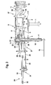
Figur 3- einen Querschnitt des Bereichs nach Figur 1.
- FIG. 1
- a front perspective view of a constant-force device having portion of a clock
- FIG. 2
- a perspective rear view of the area of Figure 1
- FIG. 3
- a cross section of the area of Figure 1.
Von einem nicht dargestellten Federhaus wird eine Kleinbodenradwelle 1 mit einer Drehspannung beaufschlagt.From a spring, not shown, a Kleinbodenradwelle 1 is acted upon by a rotary voltage.
Das auf der Kleinbodenradwelle 1 fest angeordnete Kleinbodenrad 2 steht mit einem Übertragungsrad 3 in Eingriff, das auf einem 10-Sekundenrohr 4 fest angeordnet ist.The Kleinbodenrad 2 fixedly mounted on the Kleinbodenradwelle 1 is engaged with a
Von einem ebenfalls auf dem 10-Sekundenrohr 4 fest angeordneten 10-Sekundenrad 5 wird eine Drehbewegung des 10-Sekundenrohres 4 auf einen Stoppradtrieb 6 übertragen, der fest auf einer Stoppradwelle 7 sitzt, wobei auf der Stopradwelle 7 weiterhin ein Stopprad 8 einer Schalteinheit 9 fest angeordnet ist.From a 10-
An seiner radial umlaufenden Mantelfläche besitzt das Stopprad 8 einen radial hervorstehenden Zahn 10.At its radially circumferential lateral surface, the
In derselben Ebene wie das Stopprad 8 befindet sich eine Schwinge 11, die um eine zur Drehachse der Stoppradwelle 7 parallele Schwingachse 12 schwenkbar ist.In the same plane as the
Die Schwinge 11 ist das Stopprad 8 mit radialem Abstand umgreifend ausgebildet und besitzt sich etwa diametral gegenüberliegend zwei Paletten 13, die radial zum Stopprad 8 hin ragen.The
Der Abstand der beiden Paletten 13 zueinander ist derart, daß eine der Paletten 13 in die Umlaufbahn des Zahns 10 radial hineinragt und bei Anlage des Zahns 10 an dieser Palette 13 eine Drehbewegung des Stopprades 8 blockiert, während sich die andere der Paletten 13 außerhalb der Umlaufbahn des Zahns 10 befindet.The distance between the two
Auf der der Schwingachse 12 gegenüberliegenden Seite des Stopprades 8 besitzt die Schwinge 11 eine gabelförmige Klaue 14. Diese Klaue 14 umgreift mit ihren Klauenarmen 15 eine Nockenscheibe 16 mit drei radial hervorstehenden Nocken 17.On the opposite side of the
Die Nockenscheibe 16 ist auf dem einen Ende einer Sekundenwelle 18 fest angeordnet, die sich koaxial durch das 10-Sekundenrohr 4 erstreckt und an ihrem anderen freien Ende einen Sekundenzeiger 19 trägt.The
An dem nockenscheibenseitigen Ende des 10-Sekundenrohres 4 ist auf diesem eine Halteplatte 20 eines Spannmoduls 27 befestigt, die an ihrem radial äußeren Bereich ein axial hervorstehendes Spiralklötzchen 21 trägt, das axial zur Seite der Nockenscheibe 16 hervorsteht.At the cam-side end of the 10-
An dem axial freien Ende des Spiralklötzchens 21 ist das äußere Ende einer die Sekundenwelle 18 mit Abstand umschließenden Spiralfeder 22 befestigt, während das innere Ende der Spiralfeder 22 über ein Halteteil 23 an dem Sekundenzeiger 19 befestigt ist.At the axially free end of the
Axial zwischen dem Halteteil 23 und der Halteplatte 20 trägt die Sekundenwelle 18 ein Sekundenrad 24, durch das die Drehbewegung der Sekundenwelle 18 auf ein auf einer Ankerwelle 25 angeordnetes Ankerritzel 26 übertragen wird.Axial between the
Auf der Ankerwelle 25 sitzt weiterhin ein Ankerrad 28 eines Schwingsystems 29, das als Schweizer Ankerhemmung mit Anker 30 und Unruhreif 32 sowie Unruhspiralfeder 33 aufweisender Unruh 31 ausgebildet ist.On the
Auf der Stoppradwelle 7 ist weiterhin ein Bremszwischenrad 34 angeordnet, das in ein Ritzel 35 einer Luftwirbelbremse 37 eingreift, welches auf einer Bremsenachse 36 sitzt.On the
Weiterhin sind auf der Bremsenachse 36 radial gerichtete Bremsflügel 38 angeordnet.Furthermore, 36 radially directed
Die Funktion der Vorrichtung ist folgende:
Von dem nicht dargestellten Federhaus wird das 10-Sekundenrohr 4 über das Kleinbodenrad 2 mit einer Drehspannung beaufschlagt.The function of the device is as follows:
From the spring, not shown, the 10-
Normalerweise hintergreift eine der Paletten 13 den Zahn 10 des Stopprades 8 und blockiert so dieses.Normally, one of the
Die gespannte Spiralfeder 22 treibt über die Sekundenwelle 18 das Schwingsystem 29 an und dreht die Nockenscheibe 16 mit einer Umdrehung pro Minute.The
Die Nocken 17 der Nockenscheibe 16 sind dabei in Anlage an den Klauenarmen 15 der Klaue 14 der Schwinge 11 und lenken diese in eine Schwenkrichtung aus, in der die eine Palette 13 immer mehr in Außereingriffsrichtung von dem Zahn 10 bewegt wird, bis der Zahn 10 von der Palette völlig frei gegeben wird. Dies führt dazu, daß sich das 10-Sekundenrohr 4 um einen Drehwinkel von 60° dreht und dabei über die Halteplatte 20 das Spiralklötzchen 21 verschwenkt, so daß die Spiralfeder 22 nachgespannt wird.The
Gleichzeitig wird durch die Drehung des 10-Sekundenrohres 4 über das 10-Sekundenrad 5 das nun von der einen Palette 13 freigegebene Stopprad 8 gedreht, bis der Zahn 10 nach 180° Drehung zur Anlage an der anderen Palette 13 gelangt, die durch das Verschwenken der Schwinge 11 in die Umlaufbahn des Zahns 10 gelangt ist. Nun befindet sich die Vorrichtung wieder in Normalstellung.At the same time by the rotation of the 10-
Nach zehn Sekunden ist die Schwinge 11 durch die Nocken 17 der Nokkenscheibe 16 in ihre entgegengesetzte Endposition geschwenkt und gibt mit der Palette 13 wieder den Zahn 10 frei, so daß wieder eine Nachspannung der Spiralfeder 22 wie oben beschrieben erfolgt.After ten seconds, the
- 11
- KleinbodenradwelleKleinbodenradwelle
- 22
- KleinbodenradThird wheel
- 33
- Übertragungsradtransmission wheel
- 44
- 10-Sekundenrohr10-second tube
- 55
- 10-Sekundenrad10-second wheel
- 66
- StoppradtriebStoppradtrieb
- 77
- StoppradwelleStoppradwelle
- 88th
- Stoppradstop wheel
- 99
- Schalteinheitswitching unit
- 1010
- Zahntooth
- 1111
- Schwingewing
- 1212
- Schwingachseswing axle
- 1313
- Palettenpallets
- 1414
- Klaueclaw
- 1515
- Klauenarmejaw arms
- 1616
- Nockenscheibecam
- 1717
- Nockencam
- 1818
- Sekundenwellesecond wave
- 1919
- Sekundenzeigersecond hand
- 2020
- HalteplatteRetaining plate
- 2121
- Spiralklötzchenstud
- 2222
- Spiralfederspiral spring
- 2323
- Halteteilholding part
- 2424
- SekundenradThird wheel
- 2525
- Ankerwellearmature shaft
- 2626
- Ankerritzelanchor gear
- 2727
- Spannmodulclamping module
- 2828
- Ankerradescape wheel
- 2929
- Schwingsystemoscillating system
- 3030
- Ankeranchor
- 3131
- Unruhbalance
- 3232
- Unruhreifbalance wheel
- 3333
- UnruhspiralfederUnruh spiral spring
- 3434
- BremszwischenradBremszwischenrad
- 3535
- Ritzelpinion
- 3636
- Bremsachsebrake axle
- 3737
- LuftwirbelbremseAir vortex brake
- 3838
- Bremsflügelbrake wings
Claims (17)
Applications Claiming Priority (1)
| Application Number | Priority Date | Filing Date | Title |
|---|---|---|---|
| DE102005058321A DE102005058321B4 (en) | 2005-12-07 | 2005-12-07 | Clock |
Publications (3)
| Publication Number | Publication Date |
|---|---|
| EP1795976A2 true EP1795976A2 (en) | 2007-06-13 |
| EP1795976A3 EP1795976A3 (en) | 2008-07-09 |
| EP1795976B1 EP1795976B1 (en) | 2009-04-22 |
Family
ID=37770878
Family Applications (1)
| Application Number | Title | Priority Date | Filing Date |
|---|---|---|---|
| EP06022987A Active EP1795976B1 (en) | 2005-12-07 | 2006-11-04 | Timepiece |
Country Status (4)
| Country | Link |
|---|---|
| US (1) | US7293912B2 (en) |
| EP (1) | EP1795976B1 (en) |
| DE (2) | DE102005058321B4 (en) |
| HK (1) | HK1100188A1 (en) |
Cited By (1)
| Publication number | Priority date | Publication date | Assignee | Title |
|---|---|---|---|---|
| EP2034374A2 (en) | 2007-09-07 | 2009-03-11 | Lange Uhren GmbH | Clock |
Families Citing this family (13)
| Publication number | Priority date | Publication date | Assignee | Title |
|---|---|---|---|---|
| EP1772783B1 (en) * | 2005-10-10 | 2010-06-16 | Montres Breguet S.A. | Watch movement with constant-force device |
| EP2166419B1 (en) * | 2008-09-18 | 2013-06-26 | Agenhor SA | Clockwork comprising a constant-force device |
| US8806371B2 (en) * | 2009-03-26 | 2014-08-12 | Apple Inc. | Interface navigation tools |
| EP2363762B1 (en) * | 2010-03-04 | 2017-11-22 | Montres Breguet SA | Timepiece including a high-frequency mechanical movement |
| CH702843B1 (en) * | 2010-03-17 | 2014-08-29 | Complitime Sa | Movement for timepiece to remontoir. |
| EP2397920A1 (en) * | 2010-06-17 | 2011-12-21 | Blancpain S.A. | Mechanism for a jumping tourbillon or karussel cage |
| EP2463986A1 (en) * | 2010-12-10 | 2012-06-13 | Celsius X Vi Ii | Portable electronic apparatus |
| JP6143185B2 (en) * | 2013-09-04 | 2017-06-07 | セイコーインスツル株式会社 | Operation stabilization mechanism, movement and mechanical watch |
| JP6355102B2 (en) * | 2013-09-04 | 2018-07-11 | セイコーインスツル株式会社 | Constant force devices, movements and mechanical watches |
| US9568887B2 (en) * | 2015-03-09 | 2017-02-14 | Seiko Instruments Inc. | Operation stabilizing mechanism, movement, and mechanical timepiece |
| JP6591883B2 (en) * | 2015-12-08 | 2019-10-16 | セイコーインスツル株式会社 | Constant force spring adjustment mechanism, constant force device, and mechanical watch |
| USD881058S1 (en) * | 2018-03-05 | 2020-04-14 | Montres Breguet S.A. | Escapement wheel |
| DE102020132856B3 (en) | 2020-12-09 | 2022-04-21 | Lange Uhren Gmbh | Stationary clock |
Citations (5)
| Publication number | Priority date | Publication date | Assignee | Title |
|---|---|---|---|---|
| DE288557C (en) * | ||||
| US686209A (en) * | 1901-03-19 | 1901-11-05 | Charles M Crook | Clock-winding mechanism. |
| CH251173A (en) * | 1945-10-22 | 1947-10-15 | Sandoz Borel Sophie | Constant force timepiece. |
| EP1319997A1 (en) * | 2001-12-15 | 2003-06-18 | Richemont International S.A. | Constant force device |
| EP1445669A1 (en) * | 2003-02-10 | 2004-08-11 | Richemont International S.A. | Constant force escapement mechanism for a timepiece with indirect seconds |
Family Cites Families (7)
| Publication number | Priority date | Publication date | Assignee | Title |
|---|---|---|---|---|
| US240287A (en) * | 1881-04-19 | Kasimirvogel | ||
| US1125617A (en) * | 1913-10-10 | 1915-01-19 | Elmer E Wilkinson | Automatic spring-winding mechanism for clocks. |
| US1237216A (en) * | 1915-11-17 | 1917-08-14 | Cornelius E Oeth | Self-winding clock. |
| US1385351A (en) * | 1916-12-14 | 1921-07-26 | Karl R Akerlund | Spring-motor |
| US1475629A (en) * | 1919-12-19 | 1923-11-27 | Henry J Walser | Escapement mechanism |
| US1611568A (en) * | 1925-06-30 | 1926-12-21 | Mark A Standow | Clock |
| CH120028A (en) * | 1926-07-19 | 1927-08-16 | Barbezat Bole Societe Anonyme | Constant force escapement of clockwork movement. |
-
2005
- 2005-12-07 DE DE102005058321A patent/DE102005058321B4/en not_active Expired - Fee Related
-
2006
- 2006-11-04 EP EP06022987A patent/EP1795976B1/en active Active
- 2006-11-04 DE DE502006003531T patent/DE502006003531D1/en active Active
- 2006-12-06 US US11/634,654 patent/US7293912B2/en active Active
-
2007
- 2007-07-11 HK HK07107422.6A patent/HK1100188A1/en unknown
Patent Citations (5)
| Publication number | Priority date | Publication date | Assignee | Title |
|---|---|---|---|---|
| DE288557C (en) * | ||||
| US686209A (en) * | 1901-03-19 | 1901-11-05 | Charles M Crook | Clock-winding mechanism. |
| CH251173A (en) * | 1945-10-22 | 1947-10-15 | Sandoz Borel Sophie | Constant force timepiece. |
| EP1319997A1 (en) * | 2001-12-15 | 2003-06-18 | Richemont International S.A. | Constant force device |
| EP1445669A1 (en) * | 2003-02-10 | 2004-08-11 | Richemont International S.A. | Constant force escapement mechanism for a timepiece with indirect seconds |
Cited By (3)
| Publication number | Priority date | Publication date | Assignee | Title |
|---|---|---|---|---|
| EP2034374A2 (en) | 2007-09-07 | 2009-03-11 | Lange Uhren GmbH | Clock |
| EP2034374A3 (en) * | 2007-09-07 | 2009-07-15 | Lange Uhren GmbH | Clock |
| US8038340B2 (en) | 2007-09-07 | 2011-10-18 | Lange Uhren Gmbh | Timepiece |
Also Published As
| Publication number | Publication date |
|---|---|
| US20070147179A1 (en) | 2007-06-28 |
| DE102005058321B4 (en) | 2007-09-06 |
| DE502006003531D1 (en) | 2009-06-04 |
| EP1795976B1 (en) | 2009-04-22 |
| HK1100188A1 (en) | 2007-09-07 |
| US7293912B2 (en) | 2007-11-13 |
| DE102005058321A1 (en) | 2007-06-21 |
| EP1795976A3 (en) | 2008-07-09 |
Similar Documents
| Publication | Publication Date | Title |
|---|---|---|
| EP1795976B1 (en) | Timepiece | |
| DE102007042797B4 (en) | Clock | |
| EP1319997B1 (en) | Constant force device | |
| EP1584997A2 (en) | Chronograph | |
| WO2016113704A2 (en) | Timepiece, control element and method for operating a control element with high control quality | |
| DE875629C (en) | Device for automatic winding of clocks | |
| DE3508637C1 (en) | Large clock with mechanical drive | |
| EP1517197B1 (en) | Escapement for a watch | |
| DE598651C (en) | Pointer setting device for clocks | |
| EP0451336B1 (en) | Mainspring assembly | |
| DE964966C (en) | Time switch, especially for tariff switching | |
| EP0451339B1 (en) | Repeating watch | |
| CH710662A1 (en) | Regulating device and method for operating a control element with a constant energy. | |
| DE1523901C3 (en) | Device for driving a gear jammed in its course | |
| DE77766C (en) | Clock with drive of the climbing wheel by a barrel connected between this and the mainspring | |
| DE104227C (en) | ||
| DE872027C (en) | Slave clock driven by a synchronous motor | |
| CH710845B1 (en) | Anchor escapement for mechanical movement. | |
| AT163148B (en) | Clock with increased power duration | |
| DE694156C (en) | ||
| DE125328C (en) | ||
| DE921196C (en) | Slave clock driven by synchronous motor | |
| DE201618C (en) | Spring clock. | |
| CH716172A2 (en) | Constant force device. | |
| DE901394C (en) | Alarm clock waking with pre-signals |
Legal Events
| Date | Code | Title | Description |
|---|---|---|---|
| PUAI | Public reference made under article 153(3) epc to a published international application that has entered the european phase |
Free format text: ORIGINAL CODE: 0009012 |
|
| AK | Designated contracting states |
Kind code of ref document: A2 Designated state(s): AT BE BG CH CY CZ DE DK EE ES FI FR GB GR HU IE IS IT LI LT LU LV MC NL PL PT RO SE SI SK TR |
|
| AX | Request for extension of the european patent |
Extension state: AL BA HR MK YU |
|
| REG | Reference to a national code |
Ref country code: HK Ref legal event code: DE Ref document number: 1100188 Country of ref document: HK |
|
| PUAL | Search report despatched |
Free format text: ORIGINAL CODE: 0009013 |
|
| RIC1 | Information provided on ipc code assigned before grant |
Ipc: G04B 15/10 20060101ALI20080522BHEP Ipc: G04B 1/22 20060101AFI20070301BHEP |
|
| AK | Designated contracting states |
Kind code of ref document: A3 Designated state(s): AT BE BG CH CY CZ DE DK EE ES FI FR GB GR HU IE IS IT LI LT LU LV MC NL PL PT RO SE SI SK TR |
|
| AX | Request for extension of the european patent |
Extension state: AL BA HR MK RS |
|
| 17P | Request for examination filed |
Effective date: 20080731 |
|
| GRAP | Despatch of communication of intention to grant a patent |
Free format text: ORIGINAL CODE: EPIDOSNIGR1 |
|
| GRAS | Grant fee paid |
Free format text: ORIGINAL CODE: EPIDOSNIGR3 |
|
| AKX | Designation fees paid |
Designated state(s): CH DE FR GB IT LI |
|
| GRAA | (expected) grant |
Free format text: ORIGINAL CODE: 0009210 |
|
| AK | Designated contracting states |
Kind code of ref document: B1 Designated state(s): CH DE FR GB IT LI |
|
| REG | Reference to a national code |
Ref country code: GB Ref legal event code: FG4D Free format text: NOT ENGLISH |
|
| REG | Reference to a national code |
Ref country code: CH Ref legal event code: EP |
|
| REF | Corresponds to: |
Ref document number: 502006003531 Country of ref document: DE Date of ref document: 20090604 Kind code of ref document: P |
|
| REG | Reference to a national code |
Ref country code: HK Ref legal event code: GR Ref document number: 1100188 Country of ref document: HK |
|
| PLBE | No opposition filed within time limit |
Free format text: ORIGINAL CODE: 0009261 |
|
| STAA | Information on the status of an ep patent application or granted ep patent |
Free format text: STATUS: NO OPPOSITION FILED WITHIN TIME LIMIT |
|
| 26N | No opposition filed |
Effective date: 20100125 |
|
| PG25 | Lapsed in a contracting state [announced via postgrant information from national office to epo] |
Ref country code: IT Free format text: LAPSE BECAUSE OF FAILURE TO SUBMIT A TRANSLATION OF THE DESCRIPTION OR TO PAY THE FEE WITHIN THE PRESCRIBED TIME-LIMIT Effective date: 20090422 |
|
| REG | Reference to a national code |
Ref country code: FR Ref legal event code: PLFP Year of fee payment: 10 |
|
| REG | Reference to a national code |
Ref country code: FR Ref legal event code: PLFP Year of fee payment: 11 |
|
| REG | Reference to a national code |
Ref country code: FR Ref legal event code: PLFP Year of fee payment: 12 |
|
| PGFP | Annual fee paid to national office [announced via postgrant information from national office to epo] |
Ref country code: GB Payment date: 20231123 Year of fee payment: 18 |
|
| PGFP | Annual fee paid to national office [announced via postgrant information from national office to epo] |
Ref country code: FR Payment date: 20231120 Year of fee payment: 18 Ref country code: DE Payment date: 20231121 Year of fee payment: 18 Ref country code: CH Payment date: 20231201 Year of fee payment: 18 |