EP1792701A2 - Formteilautomat mit drehbar gelagerter Form - Google Patents
Formteilautomat mit drehbar gelagerter Form Download PDFInfo
- Publication number
- EP1792701A2 EP1792701A2 EP06011062A EP06011062A EP1792701A2 EP 1792701 A2 EP1792701 A2 EP 1792701A2 EP 06011062 A EP06011062 A EP 06011062A EP 06011062 A EP06011062 A EP 06011062A EP 1792701 A2 EP1792701 A2 EP 1792701A2
- Authority
- EP
- European Patent Office
- Prior art keywords
- mold
- molding machine
- elements
- type
- machine according
- Prior art date
- Legal status (The legal status is an assumption and is not a legal conclusion. Google has not performed a legal analysis and makes no representation as to the accuracy of the status listed.)
- Withdrawn
Links
Images


Classifications
-
- B—PERFORMING OPERATIONS; TRANSPORTING
- B29—WORKING OF PLASTICS; WORKING OF SUBSTANCES IN A PLASTIC STATE IN GENERAL
- B29C—SHAPING OR JOINING OF PLASTICS; SHAPING OF MATERIAL IN A PLASTIC STATE, NOT OTHERWISE PROVIDED FOR; AFTER-TREATMENT OF THE SHAPED PRODUCTS, e.g. REPAIRING
- B29C33/00—Moulds or cores; Details thereof or accessories therefor
- B29C33/34—Moulds or cores; Details thereof or accessories therefor movable, e.g. to or from the moulding station
-
- B—PERFORMING OPERATIONS; TRANSPORTING
- B29—WORKING OF PLASTICS; WORKING OF SUBSTANCES IN A PLASTIC STATE IN GENERAL
- B29C—SHAPING OR JOINING OF PLASTICS; SHAPING OF MATERIAL IN A PLASTIC STATE, NOT OTHERWISE PROVIDED FOR; AFTER-TREATMENT OF THE SHAPED PRODUCTS, e.g. REPAIRING
- B29C44/00—Shaping by internal pressure generated in the material, e.g. swelling or foaming ; Producing porous or cellular expanded plastics articles
- B29C44/02—Shaping by internal pressure generated in the material, e.g. swelling or foaming ; Producing porous or cellular expanded plastics articles for articles of definite length, i.e. discrete articles
- B29C44/08—Shaping by internal pressure generated in the material, e.g. swelling or foaming ; Producing porous or cellular expanded plastics articles for articles of definite length, i.e. discrete articles using several expanding or moulding steps
- B29C44/083—Increasing the size of the cavity after a first part has foamed, e.g. substituting one mould part with another
- B29C44/086—Increasing the size of the cavity after a first part has foamed, e.g. substituting one mould part with another and feeding more material into the enlarged cavity
-
- B—PERFORMING OPERATIONS; TRANSPORTING
- B29—WORKING OF PLASTICS; WORKING OF SUBSTANCES IN A PLASTIC STATE IN GENERAL
- B29C—SHAPING OR JOINING OF PLASTICS; SHAPING OF MATERIAL IN A PLASTIC STATE, NOT OTHERWISE PROVIDED FOR; AFTER-TREATMENT OF THE SHAPED PRODUCTS, e.g. REPAIRING
- B29C44/00—Shaping by internal pressure generated in the material, e.g. swelling or foaming ; Producing porous or cellular expanded plastics articles
- B29C44/34—Auxiliary operations
- B29C44/36—Feeding the material to be shaped
- B29C44/38—Feeding the material to be shaped into a closed space, i.e. to make articles of definite length
- B29C44/42—Feeding the material to be shaped into a closed space, i.e. to make articles of definite length using pressure difference, e.g. by injection or by vacuum
- B29C44/428—Mould constructions; Mould supporting equipment
-
- B—PERFORMING OPERATIONS; TRANSPORTING
- B29—WORKING OF PLASTICS; WORKING OF SUBSTANCES IN A PLASTIC STATE IN GENERAL
- B29C—SHAPING OR JOINING OF PLASTICS; SHAPING OF MATERIAL IN A PLASTIC STATE, NOT OTHERWISE PROVIDED FOR; AFTER-TREATMENT OF THE SHAPED PRODUCTS, e.g. REPAIRING
- B29C44/00—Shaping by internal pressure generated in the material, e.g. swelling or foaming ; Producing porous or cellular expanded plastics articles
- B29C44/34—Auxiliary operations
- B29C44/58—Moulds
-
- B—PERFORMING OPERATIONS; TRANSPORTING
- B29—WORKING OF PLASTICS; WORKING OF SUBSTANCES IN A PLASTIC STATE IN GENERAL
- B29C—SHAPING OR JOINING OF PLASTICS; SHAPING OF MATERIAL IN A PLASTIC STATE, NOT OTHERWISE PROVIDED FOR; AFTER-TREATMENT OF THE SHAPED PRODUCTS, e.g. REPAIRING
- B29C45/00—Injection moulding, i.e. forcing the required volume of moulding material through a nozzle into a closed mould; Apparatus therefor
- B29C45/03—Injection moulding apparatus
- B29C45/04—Injection moulding apparatus using movable moulds or mould halves
- B29C45/0441—Injection moulding apparatus using movable moulds or mould halves involving a rotational movement
- B29C45/045—Injection moulding apparatus using movable moulds or mould halves involving a rotational movement mounted on the circumference of a rotating support having a rotating axis perpendicular to the mould opening, closing or clamping direction
-
- B—PERFORMING OPERATIONS; TRANSPORTING
- B29—WORKING OF PLASTICS; WORKING OF SUBSTANCES IN A PLASTIC STATE IN GENERAL
- B29C—SHAPING OR JOINING OF PLASTICS; SHAPING OF MATERIAL IN A PLASTIC STATE, NOT OTHERWISE PROVIDED FOR; AFTER-TREATMENT OF THE SHAPED PRODUCTS, e.g. REPAIRING
- B29C33/00—Moulds or cores; Details thereof or accessories therefor
- B29C33/44—Moulds or cores; Details thereof or accessories therefor with means for, or specially constructed to facilitate, the removal of articles, e.g. of undercut articles
Definitions
- the invention relates to a molding machine for the production of foam moldings according to the preamble of the main claim.
- Object of the present invention is to propose a new molding machine.
- the problem is solved in that the molding machine for producing foam moldings has at least one shape, wherein the mold is formed at least from a mold element of a first kind and a mold element of a second kind, and wherein at least two mold elements of the first type are provided, and wherein the mold elements of the first type are each alternately involved in the formation of the mold, and wherein the mold elements of the first type are arranged around a common axis of rotation, wherein the axis of rotation is rotatably mounted on the molding machine.
- the foam is often cured in a mold. To facilitate access to the form, this often consists of several features. These mold elements can be connected in such a way that together they form a negative mold for the formation of the molded part. In this case, “sections” of the form are referred to below as “shaped elements”, whereas “molded part” refers to the manufactured product.
- the form elements can be configured as desired. They may, for example, represent the shaping contour itself, but may also have a mounting frame for attachment of shaping contours and, moreover, contain integrated means for guiding the media.
- the shape often consists of several form elements, which can also be referred to as different genera.
- a mold is then formed together from each of a form element of a genus.
- a patrix may represent a first genus and a template may represent a second genus.
- shape elements of different types can be configured identically, can be designed mirror-symmetrically and can also be designed differently.
- At least two form elements of the first type are provided on the molding machine according to the invention, wherein these mold elements are each alternately involved in the formation of the mold.
- a form element genre participating in the formation of the shape is thus available several times for the formation of this shape.
- the other types of form elements involved in the formation of the mold could also be available on several occasions.
- the form elements of a genus are then each involved alternately in the formation of the form.
- another portion of the mold involved in the next process is accessible.
- preparations for the next production process can be made.
- the hitherto accessible mold element is involved in the formation of the next form of the next manufacturing process, instead of a formula element of the same type.
- follow-up of the first manufacturing process can be done.
- the preparations can be, for example, a loading with a blank and in the post-processing, for example, to remove the finished foam molding.
- the form elements of the first type are arranged around a common axis of rotation around, wherein the axis of rotation is rotatably mounted on the molding machine.
- the form elements are advantageously arranged symmetrically about the axis of rotation around. For example, in the case of two shaped elements of the first type, the shaped elements are both arranged with their backs to one another.
- the attachment of the form elements is basically arbitrary.
- the mold elements can be detached and replaced by other form elements of another genus, so that in the result increases the flexibility of such a molding machine.
- the automatic molding machine has a rotatably mounted holding device, wherein the mold elements of the first type can be fastened to the holding device.
- the formation of the holding device is basically arbitrary. It can be configured, for example, as a frame rotatably mounted on the molding machine with two opposite journals.
- At least the form elements of the first type are arranged in an easily accessible from the outside region of the molding machine.
- the form elements in particular with their forming the form page, for example, for an operator or even an automatic system for preparation and / or follow-up easily accessible.
- the form can be achieved largely directly and without obstacles. For example, there is no frame of the molding machine between and the inside of the mold elements is swept by the rotational movement to the outside.
- the mold elements each have a media supply device for process media.
- media supply means may be formed, for example, in the form of a steam chamber. Steam chambers are used for example for foaming blanks to foam moldings. However, such steam chambers are dependent on the supply of certain process media. In particular, the supply of water vapor, its dissipation and the discharge of condensed water may be required.
- the mold elements each have a media supply device for these process media.
- the media supply means can also be arranged together with the respective form element around the axis of rotation or be attached to the holding device. Then the media feeders belong to the group of moving parts.
- Each form element has its own media supply device.
- the molding machine has a media supply device for process media, wherein a connection device is provided on the molding machine, and wherein the connection device can connect the media supply device of the mold elements with the media supply device of the molding machine.
- the media supply means of the changing mold elements must be connected after each alignment of the mold elements with a stipulatezu slaughter of the molding machine. Then, as a result, a media supply to the alternately moving mold elements can be ensured.
- the stationary media supply device of the molding machine can be connected via a connecting device with the stipulatezuGermanehtung the aligned element element.
- the embodiment This connection device is basically arbitrary. However, it should be easy and quick to solve or connect, since a relatively quick change of the form elements is desired.
- An example of such a connection device is a movable telescopic tube.
- the operation of the connecting device is basically arbitrary.
- the connecting device can be actuated hydraulically and / or pneumatically. This offers the particular advantage that the control of the connecting device can be included in a fully automatic process management. In addition, such an operation at a quick change of the form elements is just as fast actuated and also solvable.
- the molding machine on at least a second mold element of the second kind, wherein the mold elements of the first genus alternately together with the first mold element of the second genus and / or with the second mold element of the second genus in the formation of a first mold and / or a second form are involved.
- the automatic molding machine has at least two mold elements of the second type. Together with the at least two form elements of the first kind, which are arranged around a common axis of rotation around, thus arise in any combination at least two forms, each formed at least from a form element of the first genus and a form element of the second genus.
- the number of form elements of the first kind and the number of form elements of the second kind is basically arbitrary. In principle, any number of form elements of the first type can be arranged around the common axis of rotation. Likewise basically any number, in particular the number of the first form elements corresponding to many, form elements of the second kind can be provided. It then results in accordance with many forms.
- a shaped element of the first kind and a shaped element of the second kind is involved in the formation of a mold.
- the form elements of the first genus are combined alternately with the form elements of the second genus.
- the first mold is first formed from the first mold member of the second genus together with the first mold member of the first genus while simultaneously or later the second mold is formed by the second mold member of the second genus together with the second mold member of the first genus.
- the number of two types of form elements is only mentioned here by way of example, and a shape can also have more than two types of form element.
- the first shape from the first shape element of the second kind together with the second shape element of the first type and simultaneously or later the second shape from the second shape element of the second kind can then be formed together with the first shape element of the first kind.
- a third or fourth or more shape would be included in the cycle.
- a molded part prepared or partially finished in the first mold may remain connected to one part of this first mold and further treated in another production section with another mold element. During this change operation of at least one molding element, the previously prepared or partially finished molding remains on at least one molding element of the first mold.
- Such a procedure saves a transfer by, for example, manual release of the prepared or partially finished molding of the first mold and introduction into the second mold. As a result, a shorter cycle time can be achieved, the manufacturing process becomes safer, which in turn improves the quality of the parts.
- the time sequence of the formation of the first and second form is basically arbitrary.
- the first mold and the second mold are formed simultaneously.
- a particularly short cycle time can be achieved.
- the design of the form elements within a genus is basically arbitrary.
- at least two form elements within a genus are designed differently, at least with regard to their shape. It can thereby be achieved that the prepared or partially finished molded part is further treated after being transferred to the second mold with a molding element of different shape, at least with regard to its shape.
- a second mold cavity which differs from the first mold cavity with respect to its shape, can be formed.
- the second mold cavity is made larger in volume than the first mold cavity.
- the additional volume can then be foamed with a second foam, so that the resulting molded part has two foam sections.
- the nature of the foam sections is basically arbitrary.
- the foam sections may be of the same or comparable consistency, but they may also differ, for example, in terms of their density or color.
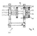
- Fig. 1 shows a molding machine 01 in a perspective view.
- the automatic molding machine 01 has a frame 02, a first mold element 03 of a first type, a second mold element 04 of the first type and a mold element 05 of a second type.
- the mold elements 03, 04 of the first type are arranged around a common axis of rotation 06, which is rotatably mounted on the frame 02 of the molding machine 01.
- the mold elements are formed as receiving arms for the attachment of shaping contours and also have integrated means for conducting the media.
- the vertical position shown in Fig. 1 is the working position in this embodiment.
- the second mold element 04 of the first type can be connected to the mold element 05 of the second type together to form. While the mold is closed and subjected to the process, the first mold element 03 of the first type is readily accessible from the outside.
- the molded elements 03, 04 of the first type are in fact arranged in an easily accessible from the outside region of the molding machine 01.
- first mold element 03 of the first type preparations can be made on the first mold element 03 of the first type.
- blanks provided for lathering may be attached to the mold element.
- the mold elements 04, 05 are separated.
- the mold element 05 of the second type moves straight back.
- the direction of rotation of the axis of rotation 06 is basically arbitrary.
- the prepared mold element 03 of the first type for forming the mold is ready in the same place as before the mold element 04 of the first kind.
- the mold element 05 of the second type is moved to the mold element 03 of the first type and connected thereto.
- the mold element 04 of the first type is accessible from the outside now at the point of the formula element 03 of the first kind.
- the finished foam molding can be removed in a post-processing step and re-assembly can take place.
- Fig. 2 shows the rotatable form elements 03, 04 of the first type in perspective view in detail. It can be seen that the mold elements 03, 04, 05 each have a steam chamber as a media supply unit exhibit. Part of the steam chambers are inlets and outlets for water vapor and water. Due to the alternating rotational movement of the mold elements 03, 04 about the axis of rotation 06, the connections of the steam chamber after alignment of the mold elements with the feeder 07 of the automatic molding machine 01 must be connected.
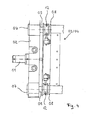
- Fig. 3 shows a molding machine according to FIG. 1 in a side view.
- the mold element 04 of the first type is here hidden by the frame 02.
- Form element 03 and 04 of the first type rotate as known in alternation about the rotation axis 06.
- the media supply 08 is one of the mold elements 03, 04 of the first genus directly in front of the Media supply device 07 of the molding machine.
- the media supply device 08 of one of the mold elements 03, 04 of the first type is alternately connected to the media supply device 07 of the automatic molding machine.
- the connection of the feeders of the element 05 of the second type can be done as known.
- Fig. 4 shows a connection device of a molding machine according to FIG. 1 between the media feeders 07, 08 of the molding machine and the formula element in detail in a side view.
- One of the form elements 03, 04 of the first type is in the aligned state directly on the frame 02 of the molding machine.
- the media supply device 07 of the automatic molding machine and the media supply device 08 of the relevant formula element are directly opposite.
- the media supply device 07 of the molding machine is designed as a continuous pipe connection through the frame 02.
- a displaceable tube 09 is provided as part of the connecting device.
- the sliding tube 09 can be each move over an actuator plate 10.
- the actuator plate 10 is actuated via the hydraulic 11.
- the connection of the media supply device 07 of the molding machine with the media supply device 08 of the relevant element element can now be secured by a closure device 12.
- the closure device 12 may have, for example, pneumatically or electrically operable flaps.
- FIG. 5 shows a further molding machine 30 having a first mold 31 and a second mold 32. Furthermore, the automatic molding machine 30 has a first mold element 33 of a first type and a second mold element 34 of the first type, which are arranged around a common axis of rotation 35 , wherein the axis of rotation 35 is rotatably mounted on the molding machine 30.
- first mold element 33 of a first type and a second mold element 34 of the first type which are arranged around a common axis of rotation 35 , wherein the axis of rotation 35 is rotatably mounted on the molding machine 30.
- the automatic molding machine 30 has a first mold element 36 of a second type and a second mold element 37 of the second type.
- At least one shaped element of the first type and one shaped element of the second type participate in the formation of the molds 31 and 32.
- the mold elements are arranged such that the two molds 31, 32 result from a transverse displacement of the mold elements 36, 37 in the direction of the mold elements 33, 34.
- the mold elements 33, 34 can swap their positions by rotation about their axis of rotation 35.
- the formation of the first mold 31 involves the mold element 36 and alternately the mold element 33 or 34
- the formation of the second mold 32 involves the formula element 37 and alternately the mold element 34 or 33.
- the molds 31, 32 can be formed simultaneously at the same time, or the molds 31, 32 are formed offset in time. This can be achieved for example by time-shifted transversal displacement of the mold elements 36, 37.
- the direction of rotation of the mold elements 33, 34 about the axis of rotation 35 is basically arbitrary.
- the shaping elements 33, 34 can rotate continuously around the rotation axis 35 in a clockwise direction, they can rotate continuously around the rotation axis 35 in a counterclockwise direction, but they can also rotate around the rotation axis 35 in an alternating clockwise and counterclockwise direction.
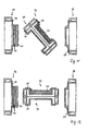
- FIG. 6 shows the shaped elements 33, 34, 36, 37 of the automatic molding machine 30 according to FIG. 5 .
- the jointly rotatable mold elements 33, 34 are designed as matrices and each have a hood 38.
- the shaped elements 36, 37 are designed as a male and have a core 39, 40 on.
- the first core 39 of the molding element 36 differs from the second core 40 of the molding element 37 with respect to its shape.
- the molding elements 36, 37 of the second type are designed differently with respect to their shape.
- the hoods 38 of the mold elements 33, 34 are, however, designed the same in this embodiment with respect to their shape.
- the automatic molding machine could also have two identical cores and two different hoods. Also arbitrary is whether the hoods or cores are rotatably provided in the center of the arrangement.
- the volume of the mold 31 in this embodiment is less than the volume of the mold 32.
- the mold 31 is therefore suitable for producing a first molding section 41.
- the second mold 32 has a larger volume than the mold 31 and is suitable for producing a second mold part section 42.
- the molding sections 41, 42 may differ, for example, by consistency, density and color and are firmly connected.
- FIGS. 7 to 14 show a manufacturing process of such a molding with two molding sections 41, 42.
- FIG. 7 shows an already foamed first molded part section 41 in the hood 38 of the molded element 34.
- the first molded part section 41 is already foamed and stabilized.
- the molds 31, 32 are then closed simultaneously. This is done by a transverse movement of the mold elements 36, 37 in the direction of the mold elements 33, 34.
- the mold 31 results from the mold elements 33, 36 and the mold 32 results from the mold elements 34, 37th
- Fig. 9 the molds 31 and 32 are closed, but not for the sake of clarity. To recognize here are the different shape cavities with respect to their shape. The different shape is due to the different cores 39, 40 ago.
- the molds 31, 32 While the molds 31, 32 are closed, they are foamed.
- the right mold 31 was originally empty and is foamed with a first molding portion 41.
- the left mold 32 was originally filled with the first mold part section 41 and is now foamed with the second mold part section 42. Because of the flatter core 40, the mold 32 results in a larger-volume cavity.
- the two molds 31, 32 After the two molds 31, 32 have been completely foamed and stabilized, they are opened again as shown in FIG .
- the first molded part section 41 just produced remains in the Hood 38 of the molding element 33 and the composite of the first molding section 41 and the second molding section 42 made in the left mold 32 remain on the core 40 of the molding element 37.
- the mold elements 36 and 37 are moved transversely away from the mold elements 33, 34 and thus the molds 31, 32 released again.
- the molding element 33 is located at the location of the molding element 34 and vice versa.
- the first mold part section 41 in the hood 38 of the mold element 33 now occupies the location of the first mold part section 41, as in FIG. 7 at the beginning of the production process, and is further processed in the next process step according to FIG. 8 ff .
- the composite of the first molding section 41 and the second molding section 42 on the core 40 of the molding element 37 was removed.
- the first mold 31 will now be in the next process step from the mold elements 34 and 36 and the mold 32 is formed in the following process steps from the mold elements 33 and 37.
- the formation of the forms 31, 32 alternately continues.
Landscapes
- Engineering & Computer Science (AREA)
- Mechanical Engineering (AREA)
- Manufacturing & Machinery (AREA)
- Moulds For Moulding Plastics Or The Like (AREA)
Abstract
Description
- Die Erfindung betrifft einen Formteilautomaten zur Herstellung von Schaumstoffformteilen nach dem Oberbegriff des Hauptanspruchs.
- Gattungsgemäße Formteilautomaten weisen häufig eine beispielsweise aus zwei Hälften bestehende Form auf. Dabei werden die zwei Formhälften während des Fertigungsprozesses des Formteils gegeneinander gedrückt. Während des Prozesses ist die eigentliche Form nicht unmittelbar zugänglich.
- Um an der Form Nachbereitungen des letzten Prozesszyklus und Vorbereitungen für den nächsten Prozesszyklus treffen zu können muss zunächst das Ende des aktuellen Fertigungszyklus abgewartet werden. Erst nachdem das fertige Formteil der Form entnommen wurde ist die Form zur Nachbereitung und/oder Vorbereitung des letzten bzw. des nächsten Prozesszyklus unmittelbar zugänglich. Diese Zeitaufwände zur Nachbereitung und/oder Vorbereitung gehen voll in die Gesamtzykluszeit mit ein und senken die Produktivität des Formteilautomaten.
- Aufgabe der vorliegenden Erfindung ist es einen neuen Formteilautomaten vorzuschlagen.
- Diese Aufgabe wird durch die vorliegende Erfindung nach der Lehre des Hauptanspruchs gelöst.
- Vorteilhafte Ausführungsformen der Erfindung sind Gegenstand der Unteransprüche.
- Erfindungsgemäß wird das Problem dadurch gelöst, dass der Formteilautomat zur Herstellung von Schaumstoffformteilen zumindest eine Form aufweist, wobei die Form zumindest aus einem Formelement einer ersten Gattung und einem Formelement einer zweiten Gattung gebildet wird, und wobei mindestens zwei Formelemente der ersten Gattung vorgesehen sind, und wobei die Formelemente der ersten Gattung jeweils wechselweise an der Bildung der Form beteiligt sind, und wobei die Formelemente der ersten Gattung um eine gemeinsame Drehachse herum angeordnet sind, wobei die Drehachse am Formteilautomaten drehbar gelagert ist.
- Bei der Herstellung von Schaumstoffformteilen wird häufig der Schaumstoff in einer Form ausgehärtet. Um den Zugang zur Form zu erleichtern besteht diese häufig aus mehreren Formelementen. Diese Formelemente können derart verbunden werden, dass sie zusammen eine Negativform für die Bildung des Formteils bilden. Dabei sind im Folgenden mit "Formelement" einzelne Abschnitte der Form bezeichnet, wohingegen mit "Formteil" das hergestellte Produkt bezeichnet wird.
- Die Formelemente können beliebig ausgestaltet sein. Sie können beispielsweise die formgebende Kontur selbst darstellen, können aber auch einen Aufnahmerahmen zur Befestigung von formgebenden Konturen aufweisen und darüber hinaus integrierte Einrichtungen zur Leitung der Medien enthalten.
- Die Form besteht häufig aus mehreren Formelementen, die auch als unterschiedliche Gattungen bezeichnet werden können. Eine Form wird dann zusammen aus jeweils einem Formelement einer Gattung gebildet. Eine Patrize kann beispielsweise eine erste Gattung darstellen und eine Matrize kann eine zweite Gattung darstellen.
- Über die Gestaltung eines Formelements einer Gattung im Vergleich zu einem Formelement einer anderen Gattung ist damit noch nichts ausgesagt. Die Formelemente verschiedener Gattungen können identisch ausgestaltet sein, können spiegelsymmetrisch ausgestaltet sein und können aber auch verschieden ausgestaltet sein.
- Am erfindungsgemäßen Formteilautomaten sind mindestens zwei Formelemente der ersten Gattung vorgesehen, wobei diese Formelemente jeweils wechselweise an der Bildung der Form beteiligt sind. In anderen Worten steht also eine an der Bildung der Form beteiligte Formelementgattung mehrfach für die Bildung dieser Form zur Verfügung. Auch die anderen an der Bildung der Form beteiligten Formelementgattungen könnten mehrfach zur Verfügung stehen.
- Die Formelemente einer Gattung werden dann jeweils wechselweise an der Bildung der Form beteiligt. Dadurch ist während der Herstellung eines Schaumstoffformteils ein anderer Abschnitt der Form, der am nächsten Prozess beteiligt ist, zugänglich. Es können dann bereits während eines Herstellungsprozesses Vorbereitungen für den nächsten Herstellungsprozess getroffen:werden. Nachdem der aktuelle Herstellungsprozess beendet wurde, wird das bis dahin zugängliche Formelement anstelle eines Formelements gleichartiger Gattung an der Bildung der nächsten Form des nächsten Herstellungsprozesses beteiligt. Während der neue Herstellungsprozess anläuft, können Nachbereitungen des ersten Herstellungsprozesses erfolgen.
- Dabei sind alle Arten von Vorbereitungen und Nachbereitungen denkbar. Bei den Vorbereitungen kann es sich beispielsweise um ein Bestücken mit einem Rohling und bei den Nachbereitungen beispielsweise um ein Entnehmen des fertigen Schaumstoffformteils handeln.
- Die Formelemente der ersten Gattung sind um eine gemeinsame Drehachse herum angeordnet, wobei die Drehachse am Formteilautomaten drehbar gelagert ist. Dabei werden die Formelemente vorteilhafterweise symmetrisch um die Drehachse herum angeordnet. Bei zwei Formelementen der ersten Gattung werden die Formelemente beispielsweise beide mit ihren Rückseiten zueinander angeordnet.
- Die Befestigung der Formelemente ist grundsätzlich beliebig. Bei lösbarer Befestigung können die Formelemente abgelöst und durch andere Formelemente einer anderen Gattung ersetzt werden, so dass sich im Ergebnis auch die Flexibilität eines solchen Formteilautomaten erhöht.
- Bei einer derartigen Anordnung der Formelemente der ersten Gattung und bei drehbarer Lagerung der Drehachse am Formteilautomaten kann durch einfache Drehung der Drehachse somit ein Wechsel des Formelements einer Gattung erfolgen. Und zwar ist die oder sind die gerade nicht am Herstellungsprozesses beteiligten Formelemente der ersten Gattung durch die Drehbewegung um die gemeinsame Drehachse immer am selben Ort erreichbar.
- Bei anderen Bewegungsarten wie beispielsweise einer translatorischen Einschiebebewegung kann nämlich das jeweils nicht am Herstellungsprozesses beteiligte Formelemente alternierend auf einer Seite des Formteilautomaten erreichbar sein. Daraus resultiert beim erfindungsgemäßen Formteilautomaten eine verbesserte Ergonomie, da der Bediener sich im wesentlichen immer am selben Ort aufhalten kann. Bei Einsatz eines automatischen Systems zur Vorbereitung und/oder Nachbereitung kommt der erfindungsgemäße Formteilautomat mit einem einzigen System aus. Auch kommt der erfindungsgemäße Formteilautomat mit einer geringeren Aufstellfläche aus.
- In einer weiteren besonders vorteilhaften Ausführungsform weist der Formteilautomat eine drehbar gelagerte Haltevorrichtung auf, wobei die Formelemente der ersten Gattung an der Haltevorrichtung befestigbar sind. Die Ausbildung der Haltevorrichtung ist dabei grundsätzlich beliebig. Sie kann beispielsweise als am Formteilautomaten drehbar gelagerter Rahmen mit zwei gegenüberliegenden Achszapfen ausgestaltet sein.
- Durch diese drehbare Ausführung eines Wechsels der Formelemente kann auch der Aufbau des Formteilautomaten im Wesentlichen relativ zu herkömmlichen Formteilautomaten unverändert bleiben. Somit ist im Ergebnis auch ein Nachrüsten durch Austausch des bisherigen Formelements der betreffenden Gattung durch eine beschriebene Drehvorrichtung möglich.
- In einer weiteren vorteilhaften Ausführungsform sind zumindest die Formelemente der ersten Gattung in einem von außen leicht erreichbaren Bereich des Formteilautomaten angeordnet. Dann nämlich sind die Formelemente insbesondere mit ihrer die Form bildenden Seite beispielsweise für einen Bediener oder aber auch ein automatisch System zur Vorbereitung und/oder Nachbereitung leicht erreichbar. Bei der Vorund/oder Nachbereitung kann die Form nämlich weitestgehend direkt und ohne Hindernisse erreicht werden. Beispielsweise steht kein Rahmen des Formteilautomaten dazwischen und die Innenseite der Formelemente wird durch die Drehbewegung nach außen gekehrt.
- In Verbindung mit um eine Drehachse angeordneten Formelementen und bei Anordnung der Drehachse in einem von außen leicht erreichbaren Bereich des Formteilautomaten wird diese vorteilhafte Wirkung noch einmal verstärkt. Dann nämlich wird stets zumindest ein Formelement um die Drehachse herum nach außen gedreht und kommt am selben Ort zum ruhen wie das vorherige Formelement. Dies ermöglicht im Ergebnis ein besonders ergonomisches Vorbereiten und/oder Nachbereiten der Form immer am selben von außen erreichbaren Ort.
- In einer weiteren vorteilhaften Ausführungsform weisen die Formelemente jeweils eine Medienzuführeinrichtung für Prozessmedien auf. Derartige Medienzuführeinrichtungen können beispielsweise in Form einer Dampfkammer gebildet werden. Dampfkammern werden beispielsweise zur Aufschäumung von Rohlingen zu Schaumstoffformteilen verwendet. Derartige Dampfkammern sind jedoch auf die Zuführung bestimmter Prozessmedien angewiesen. Insbesondere die Zuleitung von Wasserdampf, dessen Ableitung und die Ableitung von Kondenswasser können erforderlich sein.
- Um derartige Prozessmedien zur Verfügung stellen zu können weisen die Formelemente jeweils eine Medienzuführeinrichtung für diese Prozessmedien auf. Die Medienzuführeinrichtungen können auch zusammen mit dem jeweiligen Formelement um die Drehachse herum angeordnet werden oder an der Haltevorrichtung befestigt werden. Dann gehören die Medienzuführeinrichtungen zur Gruppe der bewegten Teile. Jedes Formelement weist seine eigene Medienzuführeinrichtung auf.
- In einer weiteren vorteilhaften Ausführungsform weist der Formteilautomat eine Medienzuführeinrichtung für Prozessmedien auf, wobei am Formteilautomat eine Verbindungsvorrichtung vorgesehen ist, und wobei die Verbindungsvorrichtung die Medienzuführeinrichtung der Formelemente mit der Medienzuführeinrichtung des Formteilautomaten verbinden kann.
- Die Medienzuführeinrichtung der wechselnden Formelemente muss nämlich jeweils nach Ausrichtung der Formelemente mit einer Medienzuführeinrichtung des Formteilautomaten verbunden werden. Dann kann im Ergebnis eine Medienzuführung zu den wechselnd bewegten Formelementen gewährleistet werden.
- Die stationäre Medienzuführeinrichtung des Formteilautomaten kann über eine Verbindungsvorrichtung mit der Medienzuführeinriehtung des ausgerichteten Formelements verbunden werden. Die Ausführungsform dieser Verbindungsvorrichtung ist grundsätzlich beliebig. Sie sollte sich jedoch einfach und schnell lösen bzw. verbinden lassen, da ein relativ schneller Wechsel der Formelemente erwünscht ist. Ein Beispiel einer solchen Verbindungsvorrichtung ist ein bewegliches Teleskoprohr.
- Die Betätigung der Verbindungsvorrichtung ist grundsätzlich beliebig. In einer besonders vorteilhaften Ausführungsform kann die Verbindungsvorrichtung hydraulisch und/oder pneumatisch betätigt werden. Dies bietet insbesondere den Vorteil, dass die Steuerung der Verbindungsvorrichtung in eine vollautomatische Prozessführung einbezogen werden kann. Darüber hinaus ist eine derartige Betätigung bei einem schnellen Wechsel der Formelemente ebenso schnell betätigbar und auch wieder lösbar.
- In einer weiteren vorteilhaften Ausführungsform weist der Formteilautomat zumindest ein zweites Formelement der zweiten Gattung auf, wobei die Formelemente der ersten Gattung jeweils wechselweise zusammen mit dem ersten Formelement der zweiten Gattung und/oder mit dem zweiten Formelement der zweiten Gattung an der Bildung einer ersten Form und/oder einer zweiten Form beteiligt sind.
- Bei einer derartigen Ausbildung eines Formteilautomaten mit mindestens einem zusätzlichen zweiten Formelement der zweiten Gattung weist der Formteilautomat zumindest zwei Formelemente der zweiten Gattung auf. Zusammen mit den mindestens zwei Formelementen der ersten Gattung, die um eine gemeinsame Drehachse herum angeordnet sind, ergeben sich somit in beliebiger Kombination mindestens zwei Formen, die jeweils zumindest aus einem Formelement der ersten Gattung und einem Formelement der zweiten Gattung gebildet werden.
- Die Anzahl der Formelemente der ersten Gattung und die Anzahl der Formelemente der zweiten Gattung ist jedoch grundsätzlich beliebig. Es können grundsätzlich beliebig viele Formelemente der ersten Gattung um die gemeinsame Drehachse herum angeordnet werden. Ebenfalls können grundsätzlich beliebig viele, insbesondere der Anzahl der ersten Formelemente entsprechend viele, Formelemente der zweiten Gattung vorgesehen sein. Es ergeben sich daraus dann entsprechend viele Formen.
- Jeweils ein Formelement der ersten Gattung und ein Formelement der zweiten Gattung ist an der Bildung einer Form beteiligt. Die Formelemente der ersten Gattung werden wechselweise mit den Formelementen der zweiten Gattung zusammengeführt. Dadurch wird die erste Form zunächst aus dem ersten Formelement der zweiten Gattung zusammen mit dem ersten Formelement der ersten Gattung gebildet während gleichzeitig oder später die zweite Form durch das zweite Formelement der zweiten Gattung zusammen mit dem zweiten Formelement der ersten Gattung gebildet wird. Die Anzahl von zwei Formelementgattungen ist hier nur exemplarisch erwähnt, eine Form kann auch mehr als zwei Formelementgattungen aufweisen. Nachfolgend kann dann die erste Form aus dem ersten Formelement der zweiten Gattung zusammen mit dem zweiten Formelement der ersten Gattung und gleichzeitig oder später die zweite Form aus dem zweitem Formelement der zweiten Gattung zusammen mit dem ersten Formelement der ersten Gattung gebildet werden. Bei mehr als zwei Formelementen je Gattung würde eine dritte bzw. vierte oder weitere Form in den Wechselzyklus miteinbezogen.
- Besondere Vorteile eines derartigen Formteilautomaten ergeben sich dadurch, dass im Formteilproduktionszyklus zumindest ein Teil der einen Form auch Teil der anderen Form ist. So kann beispielsweise ein in der ersten Form vorbereitetes oder teilweise fertiggestelltes Formteil an einem Teil dieser ersten Form verbunden bleiben und in einem weiteren Produktionsabschnitt mit einem anderen Formelement weiterbehandelt werden. Während dieses Wechselvorgangs zumindest eines Formelements verbleibt das zuvor vorbereitete oder teilweise fertiggestellte Formteil an zumindest einem Formelement der ersten Form.
- Eine derartige Vorgehensweise erspart ein Transferieren durch beispielsweise manuelles Herauslösen des vorbereiteten oder teilweise fertiggestellten Formteils aus der ersten Form und Einbringen in die zweite Form. Dadurch kann eine kürzere Zykluszeit erreicht werden, der Herstellungsprozess wird sicherer, wodurch wiederum die Teilequalität verbessert wird.
- Die zeitliche Abfolge der Bildung der ersten und zweiten Form ist grundsätzlich beliebig. In einer besonders vorteilhaften Ausführungsform wird die erste Form und die zweite Form simultan gebildet. Dadurch lässt sich eine besonders kurze Zykluszeit erreichen. Es wäre aber ebenfalls realisierbar in einem ersten Schritt die erste Form und in einem zweiten Schritt die zweite Form zu bilden.
- Die Ausgestaltung der Formelemente innerhalb einer Gattung ist grundsätzlich beliebig. In einer besonders vorteilhaften Ausführungsform sind mindestens zwei Formelemente innerhalb einer Gattung zumindest bezüglich ihrer Formgebung unterschiedlich ausgestaltet. Dadurch kann erreicht werden, dass das vorbereitete oder teilweise fertiggestellte Formteil nach der Übergabe in die zweite Form mit einem zumindest bezüglich seiner Formgebung unterschiedlich ausgestalteten Formelement weiterbehandelt wird.
- So kann sich beispielsweise durch die unterschiedliche Formgebung der die zweite Form bildenden Formelemente eine bezüglich ihrer Formgebung sich von der ersten Formkavität unterscheidende zweite Formkavität ausbilden. So ist es möglich, dass die zweite Formkavität bezüglich ihres Volumens größer ausgebildet wird als die erste Formkavität. Das zusätzliche Volumen kann dann mit einem zweiten Schaum ausgeschäumt werden, so dass das entstehende Formteil zwei Schaumstoffabschnitte aufweist.
- Die Beschaffenheit der Schaumstoffabschnitte ist grundsätzlich beliebig. Die Schaumstoffabschnitte können von gleicher oder vergleichbarer Konsistenz sein, sie können sich aber auch beispielsweise bezüglich ihrer Dichte oder Farbe unterscheiden.
- Wie viele Formelemente innerhalb einer Gattung sich zumindest bezüglich ihrer Formgebung unterscheiden ist grundsätzlich beliebig. Es können sich alle Formelemente innerhalb einer Gattung zumindest bezüglich ihrer Formgebung unterscheiden, es können aber auch einige bezüglich ihrer Formgebung gleiche oder vergleichbare Formelemente innerhalb einer Gattung und zusätzlich innerhalb derselben Gattung zumindest bezüglich ihrer Formgebung unterschiedlich ausgestaltete Formelemente vorgesehen sein. Weiterhin ist es möglich auch eine Unterscheidung zumindest bezüglich der Formgebung innerhalb der ersten und zusätzlich innerhalb der zweiten Gattung vorzusehen.
- Ob die Unterscheidung an den um die gemeinsame Drehachse herum angeordneten Formelementen der ersten Gattung oder an den Formelementen der zweiten Gattung vorgesehen ist ist grundsätzlich beliebig.
- Einige Ausführungsformen der Erfindung sind in den Zeichnungen dargestellt und werden nachfolgend beispielhaft erläutert.
- Es zeigen:
- Fig. 1
- einen ersten Formteilautomat in perspektivischer Ansicht;
- Fig. 2
- drehbare Haltevorrichtung eines Formteilautomaten gemäß Fig. 1 und Fig. 5 in perspektivischer Ansicht;
- Fig. 3
- Formteilautomat gemäß Fig. 1 in seitlicher Ansicht;
- Fig. 4
- Verbindungsvorrichtung eines Formteilautomaten gemäß Fig. 1 und Fig. 5 in seitlicher Ansicht.
- Fig. 5
- einen zweiten Formteilautomaten in seitlicher Ansicht;
- Fig. 6
- Formelemente mit Formteilen eines Formteilautomaten gemäß Fig. 5;
- Fig. 7
- Formelemente gemäß Fig. 6 in einem ersten Abschnitt eines Formteil-Herstellungsprozesses;
- Fig. 8
- Formelemente gemäß Fig. 6 in einem zweiten Abschnitt eines Formteil-Herstellungsprozesses;
- Fig. 9
- Formelemente gemäß Fig. 6 in einem dritten Abschnitt eines Formteil-Herstellungsprozesses;
- Fig. 10
- Formelemente gemäß Fig. 6 in einem vierten Abschnitt eines Formteil-Herstellungsprozesses;
- Fig. 11
- Formelemente gemäß Fig. 6 in einem fünften Abschnitt eines Formteil-Herstellungsprozesses;
- Fig. 12
- Formelemente gemäß Fig. 6 in einem sechsten Abschnitt eines Formteil-Herstellungsprozesses;
- Fig. 13
- Formelemente gemäß Fig. 6 in einem siebten Abschnitt eines Formteil-Herstellungsprozesses;
- Fig. 14
- Formelemente gemäß Fig. 6 in einem achten Abschnitt eines Formteil-Herstellungsprozesses.
- Fig. 1 zeigt einen Formteilautomaten 01 in perspektivischer Ansicht. Der Formteilautomat 01 weist einen Rahmen 02, ein erstes Formelement 03 einer ersten Gattung, ein zweites Formelement 04 der ersten Gattung sowie ein Formelement 05 einer zweiten Gattung auf. Die Formelemente 03, 04 der ersten Gattung sind um eine gemeinsame Drehachse 06 angeordnet, die am Rahmen 02 des Formteilautomaten 01 drehbar gelagert ist.
- In diesem Ausführungsbeispiel sind die Formelemente als Aufnahmerabmen zur Befestigung von formgebenden Konturen ausgebildet und weisen darüber hinaus integrierte Einrichtungen zur Leitung der Medien auf.
- Die in Fig. 1 dargestellte senkrechte Position ist in dieser Ausführungsform die Arbeitsposition. Dabei kann das zweite Formelement 04 der ersten Gattung mit dem Formelement 05 der zweiten Gattung zusammen zur Form verbunden werden. Während die Form geschlossen ist und dem Prozess unterzogen wird ist das erste Formelement 03 der ersten Gattung von außen her problemlos zugänglich. Die Formelemente 03, 04 der ersten Gattung sind nämlich in einem von außen leicht erreichbaren Bereich des Formteilautomaten 01 angeordnet.
- Während das zweite Formelement 04 der ersten Gattung in den Schäumprozess einbezogen ist können am ersten Formelement 03 der ersten Gattung Vorbereitungen getroffen werden. Beispielsweise können zur Einschäumung vorgesehene Rohlinge an dem Formelement angebracht werden.
- Nachdem der aktive Herstellungsprozess beendet ist werden die Formelemente 04, 05 getrennt. Dabei fährt das Formelement 05 der zweiten Gattung geradlinig zurück. Es erfolgt eine Drehung der Formelemente 03, 04 der ersten Gattung um die Drehachse 06 herum um 180°. Der Drehsinn der Drehachse 06 ist grundsätzlich beliebig. Nun befindet sich das vorbereitete Formelement 03 der ersten Gattung zur Bildung der Form bereit an der selben Stelle wie zuvor das Formelement 04 der ersten Gattung. Dazu wird das Formelement 05 der zweiten Gattung auf das Formelement 03 der ersten Gattung zu bewegt und mit diesem verbunden.
- Währenddessen befindet sich das Formelement 04 der ersten Gattung von außen erreichbar nun an der Stelle des Formelements 03 der ersten Gattung. Das fertige Schaumstoffformteil kann in einem Nachbereitungsschritt entnommen werden und eine erneute Bestückung kann erfolgen.
- Fig. 2 zeigt die drehbaren Formelemente 03, 04 der ersten Gattung in perspektivischer Ansicht im Detail. Zu erkennen ist, dass die Formelemente 03, 04, 05 jeweils eine Dampfkammer als Medienzuführeinheit aufweisen. Bestandteil der Dampfkammern sind jeweils Zu- und Abgänge für Wasserdampf und Wasser. Durch die wechselweise Drehbewegung der Formelemente 03, 04 um die Drehachse 06 müssen die Anschlüsse der Dampfkammer nach Ausrichtung der Formelemente mit der Zuführeinrichtung 07 des Formteilautomaten 01 verbunden werden.
- Fig. 3 zeigt einen Formteilautomaten gemäß Fig. 1 in seitlicher Ansicht. Das Formelement 04 der ersten Gattung ist hier verdeckt durch den Rahmen 02. Formelement 03 und 04 der ersten Gattung rotieren wie bekannt im Wechsel um die Drehachse 06. Dabei befindet sich jeweils die Medienzuführeinrichtung 08 eines der Formelemente 03, 04 der ersten Gattung direkt vor der Medienzuführeinrichtung 07 des Formteilautomaten. Es wird also wechselweise die Medienzuführeinrichtung 08 eines der Formelemente 03, 04 der ersten Gattung mit der Medienzuführeinrichtung 07 des Formteilautomaten verbunden. Die Verbindung der Zuführeinrichtungen des Formelements 05 der zweiten Gattung kann wie bekannt erfolgen.
- Fig. 4 zeigt eine Verbindungseinrichtung eines Formteilautomaten gemäß Fig. 1 zwischen den Medienzuführeinrichtungen 07, 08 des Formteilautomaten und des Formelements im Detail in seitlicher Ansicht. Eines der Formelemente 03, 04 der ersten Gattung befindet sich im ausgerichteten Zustand direkt am Rahmen 02 des Formteilautomaten. Somit stehen sich im Ergebnis in dieser Ausführungsform der Erfindung die Medienzuführeinrichtung 07 des Formteilautomaten und die Medienzuführeinrichtung 08 des betreffenden Formelements direkt gegenüber. Die Medienzuführeinrichtung 07 des Formteilautomaten ist als durchgängige Rohrverbindung durch den Rahmen 02 ausgestaltet.
- Zur Verbindung der Medienzuführeinrichtungen 07 des Formteilautomaten mit der Medienzuführeinrichtung 08 des betreffenden Formelements ist hier jeweils ein verschiebbares Rohr 09 als Bestandteil der Verbindungsvorrichtung vorgesehen. Das verschiebbare Rohr 09 lässt sich jeweils über eine Betätigungsplatte 10 bewegen. Die Betätigungsplatte 10 wird über die Hydraulik 11 betätigt.
- Die Verbindung der Medienzuführeinrichtung 07 des Formteilautomaten mit der Medienzuführeinrichtung 08 des betreffenden Formelements kann nun über eine Verschlusseinrichtung 12 gesichert werden. Die Verschlusseinrichtung 12 kann beispielsweise pneumatisch oder auch elektrisch betätigbare Klappen aufweisen.
- Fig. 5 zeigt einen weiteren Formteilautomaten 30 mit einer ersten Form 31 und einer zweiten Form 32. Weiterhin weist der Formteilautomat 30 ein erstes Formelement 33 einer ersten Gattung und ein zweites Formelement 34 der ersten Gattung auf, die um eine gemeinsame Drehachse 35 herum angeordnet sind, wobei die Drehachse 35 am Formteilautomaten 30 drehbar gelagert ist. Für die Verbindung der Formelemente 33, 34 mit der Drehachse 35 wird vollinhaltlich auf die Ausführungen zu den Figuren 1. bis 4 verwiesen.
- Weiterhin weist der Formteilautomat 30 ein erstes Formelement 36 einer zweiten Gattung sowie ein zweites Formelement 37 der zweiten Gattung auf.
- An der Bildung der Formen 31 und 32 ist jeweils zumindest ein Formelement der ersten Gattung und ein Formelement der zweiten Gattung beteiligt. Die Formelemente sind derart angeordnet, dass durch eine Transversalverschiebung der Formelemente 36, 37 in Richtung auf die Formelemente 33, 34 sich die zwei Formen 31, 32 ergeben.
- Die Formelemente 33, 34 können durch Rotation um ihre Drehachse 35 ihre Positionen tauschen. Dadurch ist an der Bildung der ersten Form 31 das Formelement 36 und wechselweise das Formelement 33 oder 34 beteiligt und an der Bildung der zweiten Form 32 ist das Formelelement 37 und wechselweise das Formelement 34 oder 33 beteiligt.
- Die Formen 31, 32 können dabei zeitgleich also simultan gebildet werden oder die Formen 31, 32 werden zeitlich versetzt gebildet. Dies kann beispielsweise durch zeitversetztes transversales Verschieben der Formelemente 36, 37 erreicht werden.
- Die Rotationsrichtung der Formelemente 33, 34 um die Drehachse 35 ist grundsätzlich beliebig. Die Formelemente 33, 34 können kontinuierlich im Uhrzeigersinn um die Drehachse 35 herumrotieren, sie können kontinuierlich gegen den Uhrzeigersinn um die Drehachse 35 herumrotieren, sie können beispielsweise aber auch alternierend mit und gegen den Uhrzeigersinn um die Drehachse 35 herumrotieren.
- Fig. 6 zeigt die Formelemente 33, 34, 36, 37 des Formteilautomaten 30 gemäß Fig. 5. Die gemeinsam rotierbaren Formelemente 33, 34, sind als Matrizen ausgestaltet und weisen jeweils eine Haube 38 auf.
- Die Formelemente 36, 37 sind hingegen als Patrizen ausgestaltet und weisen einen Kern 39, 40 auf. Der erste Kern 39 des Formelements 36 unterscheidet sich bezüglich seiner Formgebung vom zweiten Kern 40 des Formelements 37. Somit sind die Formelemente 36, 37 der zweiten Gattung bezüglich ihrer Formgebung unterschiedlich ausgestaltet. Die Hauben 38 der Formelemente 33, 34 sind hingegen in diesem Ausführungsbeispiel bezüglich ihrer Formgebung gleich ausgestaltet.
- Grundsätzlich könnte der Formteilautomat auch zwei gleiche Kerne und zwei unterschiedliche Hauben aufweisen. Ebenfalls beliebig ist ob die Hauben oder die Kerne rotierbar in der Mitte der Anordnung vorgesehen sind.
- In diesem Ausführungsbeispiel ergibt sich aufgrund der unterschiedlichen Formgebung der Kerne 39 und 40 ein unterschiedliches Kavitätsvolumen in den Formen 31 und 32. Das Volumen der Form 31 ist in diesem Ausführungsbeispiel geringer als das Volumen der Form 32. Die Form 31 ist daher geeignet zur Herstellung eines ersten Formteilabschnitts 41. Die zweite Form 32 weist aufgrund des unterschiedlichen Kerns 40 ein größeres Volumen als die Form 31 auf und ist zur Herstellung eines zweiten Formteilabschnitts 42 geeignet. Die Formteilabschnitte 41, 42 können sich beispielsweise durch Konsistenz, Dichte und Farbe unterscheiden und sind fest miteinander verbunden.
- Fig. 7 bis 14 zeigen einen Herstellungsprozess eines derartigen Formteils mit zwei Formteilabschnitten 41, 42.
- Fig. 7 zeigt einen bereits ausgeschäumten ersten Formteilabschnitt 41 in der Haube 38 des Formelements 34. Der erste Formteilabschnitt 41 ist bereits ausgeschäumt und stabilisiert.
- Wie in Fig. 8 dargestellt werden dann die Formen 31, 32 simultan geschlossen. Dies erfolgt durch eine Transversalbewegung der Formelemente 36, 37 in Richtung auf die Formelemente 33, 34. Die Form 31 ergibt sich aus den Formelementen 33, 36 und die Form 32 ergibt sich aus den Formelementen 34, 37.
- In Fig. 9 sind die Formen 31 und 32 geschlossen, der Übersicht halber jedoch nicht bezeichnet. Zu erkennen sind hier die bezüglich ihrer Formgebung unterschiedlichen Formkavitäten. Die unterschiedliche Formgebung rührt von den unterschiedlichen Kernen 39, 40 her.
- Während die Formen 31, 32 geschlossen sind werden sie ausgeschäumt. Die rechte Form 31 ist ursprünglich leer gewesen und wird mit einem ersten Formteilabschnitt 41 ausgeschäumt. Die linke Form 32 war ursprünglich mit dem ersten Formteilabschnitt 41 befüllt und wird nun mit dem zweiten Formteilabschnitt 42 ausgeschäumt. Aufgrund des flacher ausgestalteten Kerns 40 ergibt sich in der Form 32 eine großvolumigere Kavität.
- Nachdem die zwei Formen 31, 32 vollständig ausgeschäumt und stabilisiert worden sind werden sie wieder wie in Fig. 10 dargestellt geöffnet. Dabei verbleibt der soeben hergestellte erste Formteilabschnitt 41 in der Haube 38 des Formelements 33 und der in der linken Form 32 hergestellte Verbund aus erstem Formteilabschnitt 41 und zweitem Formteilabschnitt 42 verbleibt am Kern 40 des Formelements 37.
- Die Formelemente 36 und 37 werden transversal von den Formelementen 33, 34 wegbewegt und somit die Formen 31, 32 wieder freigegeben.
- Sodann erfolgt wie in Fig. 11 dargestellt die Rotation der Formelemente 33, 34 zusammen mit dem immer noch sich in der Haube 38 des Formelements 33 befindlichen ersten Formteilabschnitts 41. Der Verbund aus erstem Formteilabschnitt 41 und zweitem Formteilabschnitt 42 verbleibt weiterhin am Kern 40 des Formelements 37.
- Sodann wie in Fig. 12 dargestellt die Rotation der Formelemente 33, 34 zusammen mit dem immer noch sich in der Haube 38 des Formelements 33 befindlichen ersten Formteilabschnitts 41. Der Verbund aus erstem Formteilabschnitt 41 und zweitem Formteilabschnitt 42 verbleibt weiterhin am Kern 40 des Formelements 37.
- Sodann wie in Fig. 13 dargestellt die Rotation der Formelemente 33, 34 zusammen mit dem immer noch sich in der Haube 38 des Formelements 33 befindlichen ersten Formteilabschnitts 41. Der Verbund aus erstem Formteilabschnitt 41 und zweitem Formteilabschnitt 42 verbleibt weiterhin am Kern 40 des Formelements 37.
- Zum Schluss der Rotation befindet sich wie in Fig. 14 dargestellt das Formelement 33 an der Stelle des Formelements 34 und umgekehrt. Der erste Formteilabschnitt 41 in der Haube 38 des Formelements 33 nimmt nun die Stelle des ersten Formteilabschnitts 41, wie in Fig. 7 am Anfang des Herstellungsprozesses, ein und wird im nächsten Prozessschritt der gemäß Fig. 8 ff. erfolgt weiterbehandelt. Der Verbund aus erstem Formteilabschnitt 41 und zweitem Formteilabschnitt 42 am Kern 40 des Formelements 37 wurde entnommen. Die erste Form 31 wird nun im nächsten Prozessschritt aus den Formelementen 34 und 36 und die Form 32 wird in folgenden Prozessschritten aus den Formelementen 33 und 37 gebildet. Die Bildung der Formen 31, 32 vollzieht sich wechselweise so weiter.
Claims (11)
- Formteilautomat (01, 30) zur Herstellung von Schaumstoffformteilen, wobei der Formteilautomat (01, 30) zumindest eine Form (31) aufweist, und wobei die Form (31) zumindest aus einem Formelement (04, 33) einer ersten Gattung und einem Formelement (05, 36) einer zweiten Gattung gebildet wird, und wobei mindestens zwei Formelemente (03, 04, 33, 34) der ersten Gattung vorgesehen sind, und wobei die Formelemente (03, 04, 33, 34) der ersten Gattung jeweils wechselweise an der Bildung der Form (31) beteiligt sind,
dadurch gekennzeichnet,
dass die Formelemente (03, 04, 33, 34) der ersten Gattung um eine gemeinsame Drehachse (06, 35) herum angeordnet sind, wobei die Drehachse (06, 35) am Formteilautomaten (01, 30) drehbar gelagert ist. - Formteilautomat nach Anspruch 1,
dadurch gekennzeichnet,
dass der Formteilautomat (01, 30) eine drehbar gelagerte Haltevorrichtung aufweist, wobei die Formelemente (03, 04, 33, 34) der ersten Gattung an der Haltevorrichtung befestigbar sind. - Formteilautomat nach Anspruch 1 oder 2,
dadurch gekennzeichnet,
dass die Drehachse (06, 35) horizontal angeordnet ist. - Formteilautomat nach einem der Ansprüche 1 bis 3,
dadurch gekennzeichnet,
dass zumindest die Formelemente (03, 04, 33, 34) der ersten Gattung in einem von außen leicht erreichbaren Bereich des Formteilautomaten (01, 30) angeordnet sind. - Formteilautomat nach einem der Ansprüche 1 bis 4,
dadurch gekennzeichnet,
dass zumindest die Formelemente (03, 04, 33, 34) der ersten Gattung wechselweise in einen von außen gut zugänglichen Bereich des Formteilautomaten (01, 30) eingeschwenkt werden können. - Formteilautomat nach einem der Ansprüche 1 bis 5,
dadurch gekennzeichnet,
dass die Formelemente (03, 04, 33, 34) jeweils eine Zuführeinrichtung (08) für Prozessmedien aufweisen. - Formteilautomat nach Anspruch 6,
dadurch gekennzeichnet,
dass der Formteilautomat (01, 30) eine Zuführeinrichtung (07) für Prozessmedien aufweist, wobei am Formteilautomat (01, 30) eine Verbindungsvorrichtung (09, 10) vorgesehen ist, und wobei die Verbindungsvorrichtung (09, 10) die Zuführeinrichtung (08) der Formelemente mit der Zuführeinrichtung (07) des Formteilautomaten (01, 30) verbinden kann. - Formteilautomat nach Anspruch 7,
dadurch gekennzeichnet,
dass die Verbindungsvorrichtung (09, 10) hydraulisch und/oder pneumatisch betätigt werden kann. - Formteilautomat nach einem der Ansprüche 1 bis 8,
dadurch gekennzeichnet,
dass der Formteilautomat (30) zumindest ein zweites Formelement (37) der zweiten Gattung aufweist, wobei die Formelemente (33, 34) der ersten Gattung jeweils wechselweise zusammen mit dem ersten Formelement (36) der zweiten Gattung und/oder mit dem zweiten Formelement (37) der zweiten Gattung an der Bildung einer ersten Form (31) und/oder einer zweiten Form (32) beteiligt sind. - Formteilautomat nach Anspruch 9,
dadurch gekennzeichnet,
dass die erste Form (31) und die zweite Form (32) simultan gebildet werden. - Formteilautomat nach Anspruch 9 oder 10,
dadurch gekennzeichnet,
dass mindestens zwei Formelemente (36, 37) innerhalb einer Gattung zumindest bezüglich ihrer Formgebung unterschiedlich ausgestaltet sind.
Applications Claiming Priority (1)
| Application Number | Priority Date | Filing Date | Title |
|---|---|---|---|
| DE200520019021 DE202005019021U1 (de) | 2005-12-05 | 2005-12-05 | Formteilautomat mit rotierender Form |
Publications (2)
| Publication Number | Publication Date |
|---|---|
| EP1792701A2 true EP1792701A2 (de) | 2007-06-06 |
| EP1792701A3 EP1792701A3 (de) | 2011-06-08 |
Family
ID=36202301
Family Applications (1)
| Application Number | Title | Priority Date | Filing Date |
|---|---|---|---|
| EP06011062A Withdrawn EP1792701A3 (de) | 2005-12-05 | 2006-05-30 | Formteilautomat mit drehbar gelagerter Form |
Country Status (2)
| Country | Link |
|---|---|
| EP (1) | EP1792701A3 (de) |
| DE (1) | DE202005019021U1 (de) |
Families Citing this family (2)
| Publication number | Priority date | Publication date | Assignee | Title |
|---|---|---|---|---|
| DE102006021021A1 (de) * | 2006-05-05 | 2007-11-15 | Krauss Maffei Gmbh | Verfahren zur Herstellung eines Mehrschichtteiles |
| DE102018211737B4 (de) * | 2018-07-13 | 2020-02-13 | Erlenbach Gmbh | Maschinensystem, Formteilmaschine, Werkzeugblock und Verfahren zum Ausrüsten einer Formteilmaschine |
Citations (2)
| Publication number | Priority date | Publication date | Assignee | Title |
|---|---|---|---|---|
| DE2709450B1 (de) * | 1977-03-04 | 1978-05-03 | Kurtz Fa Ph | Maschine zum zweistufigen Herstellen von geschaeumten Thermoplastformteilen |
| EP1512511A2 (de) * | 2001-08-03 | 2005-03-09 | Krauss-Maffei Kunststofftechnik GmbH | Formschliessvorrichtung für eine Spritzgiessmaschine |
-
2005
- 2005-12-05 DE DE200520019021 patent/DE202005019021U1/de not_active Expired - Lifetime
-
2006
- 2006-05-30 EP EP06011062A patent/EP1792701A3/de not_active Withdrawn
Patent Citations (2)
| Publication number | Priority date | Publication date | Assignee | Title |
|---|---|---|---|---|
| DE2709450B1 (de) * | 1977-03-04 | 1978-05-03 | Kurtz Fa Ph | Maschine zum zweistufigen Herstellen von geschaeumten Thermoplastformteilen |
| EP1512511A2 (de) * | 2001-08-03 | 2005-03-09 | Krauss-Maffei Kunststofftechnik GmbH | Formschliessvorrichtung für eine Spritzgiessmaschine |
Also Published As
| Publication number | Publication date |
|---|---|
| DE202005019021U1 (de) | 2006-03-30 |
| EP1792701A3 (de) | 2011-06-08 |
Similar Documents
| Publication | Publication Date | Title |
|---|---|---|
| DE3213256C2 (de) | Spritzgießeinrichtung mit einer ersten und einer zweiten Form zum Herstellen eines Ventilatorgitters | |
| DE69514615T2 (de) | Giessverfahren und Vorrichtung | |
| DE69826526T2 (de) | Verfahren und gerät zum formen eines zusammengesetzten gegenstands | |
| DE69109458T2 (de) | Ein mehrschichtiges Rohr aus Kunststoff und Verfahren zu dessen Herstellung. | |
| DE3639313A1 (de) | Rueckwaertig zu oeffnende formeinrichtung | |
| DE3519921A1 (de) | Giessform mit beheiztem angusskanal fuer spritzgiessen | |
| CH342368A (de) | Verfahren und Maschine zur Herstellung von Flaschen aus plastischem Material | |
| EP3401037B1 (de) | Form zum herstellen eines giesskerns | |
| DE10053199B4 (de) | Verfahren zum Herstellen eines Metallverbundstoff-Presslings | |
| EP2988913A2 (de) | Werkzeug zur herstellung eines faser-kunststoff-verbund-bauteils mit wenigstens einer entlüftungsbohrung und darin angeordnetem auswerferstift | |
| DE69319243T2 (de) | Verfahren und vorrichtung zum herstellen von thermoplastischen kunststoffschrauben | |
| DE4303588A1 (de) | ||
| DE2917913A1 (de) | Dorn mit einziehbaren segmenten | |
| EP0074473B1 (de) | Verfahren und Vorrichtung zur Herstellung von Formteilen oder Gegenständen aus Kunststoff | |
| DE2233395A1 (de) | Spritzgussform mit auswerfereinrichtung | |
| WO2024120575A1 (de) | Verfahren zur herstellung von kunststoffrollen und formwerkzeug | |
| EP0464411A1 (de) | Vorrichtung zur Herstellung von Kunststoff-Rohren | |
| EP1792701A2 (de) | Formteilautomat mit drehbar gelagerter Form | |
| WO2019076536A1 (de) | DRUCKGUSSFORM ZUM GIEßEN VON ZYLINDERKURBELGEHÄUSEN ODER KURBELGEHÄUSEUNTERTEILEN | |
| DE19747573C2 (de) | Spritzeinheitsverbindungsvorrichtung für eine Mehrschichtspritzformmaschine | |
| EP2522464A2 (de) | Pressbacke und Verfahren zum Herstellen einer Pressverbindung | |
| DE202016103268U1 (de) | Auswurfvorrichtung für ein Werrkzeug zur Herstellung eines Formteils | |
| DE60111611T2 (de) | Verfahren und vorrichtung zum spritzgiessen | |
| DE1552182B2 (de) | Vorrichtung zum Radialpressen von Verzahnungen | |
| DE102009031604A1 (de) | Sandgusswerkzeug |
Legal Events
| Date | Code | Title | Description |
|---|---|---|---|
| PUAI | Public reference made under article 153(3) epc to a published international application that has entered the european phase |
Free format text: ORIGINAL CODE: 0009012 |
|
| AK | Designated contracting states |
Kind code of ref document: A2 Designated state(s): AT BE BG CH CY CZ DE DK EE ES FI FR GB GR HU IE IS IT LI LT LU LV MC NL PL PT RO SE SI SK TR |
|
| AX | Request for extension of the european patent |
Extension state: AL BA HR MK YU |
|
| PUAL | Search report despatched |
Free format text: ORIGINAL CODE: 0009013 |
|
| AK | Designated contracting states |
Kind code of ref document: A3 Designated state(s): AT BE BG CH CY CZ DE DK EE ES FI FR GB GR HU IE IS IT LI LT LU LV MC NL PL PT RO SE SI SK TR |
|
| AX | Request for extension of the european patent |
Extension state: AL BA HR MK YU |
|
| RIC1 | Information provided on ipc code assigned before grant |
Ipc: B29C 44/08 20060101ALI20110429BHEP Ipc: B29C 33/34 20060101ALI20110429BHEP Ipc: B29C 44/58 20060101AFI20070309BHEP |
|
| AKY | No designation fees paid | ||
| REG | Reference to a national code |
Ref country code: DE Ref legal event code: R108 Effective date: 20120215 |
|
| STAA | Information on the status of an ep patent application or granted ep patent |
Free format text: STATUS: THE APPLICATION IS DEEMED TO BE WITHDRAWN |
|
| 18D | Application deemed to be withdrawn |
Effective date: 20111209 |