EP1791704B1 - Gleitschutzvorrichtung für fahrzeugräder - Google Patents
Gleitschutzvorrichtung für fahrzeugräder Download PDFInfo
- Publication number
- EP1791704B1 EP1791704B1 EP05773738A EP05773738A EP1791704B1 EP 1791704 B1 EP1791704 B1 EP 1791704B1 EP 05773738 A EP05773738 A EP 05773738A EP 05773738 A EP05773738 A EP 05773738A EP 1791704 B1 EP1791704 B1 EP 1791704B1
- Authority
- EP
- European Patent Office
- Prior art keywords
- chain
- skid device
- strands
- links
- intermediate link
- Prior art date
- Legal status (The legal status is an assumption and is not a legal conclusion. Google has not performed a legal analysis and makes no representation as to the accuracy of the status listed.)
- Expired - Lifetime
Links
Images

Classifications
-
- B—PERFORMING OPERATIONS; TRANSPORTING
- B60—VEHICLES IN GENERAL
- B60C—VEHICLE TYRES; TYRE INFLATION; TYRE CHANGING; CONNECTING VALVES TO INFLATABLE ELASTIC BODIES IN GENERAL; DEVICES OR ARRANGEMENTS RELATED TO TYRES
- B60C27/00—Non-skid devices temporarily attachable to resilient tyres or resiliently-tyred wheels
- B60C27/06—Non-skid devices temporarily attachable to resilient tyres or resiliently-tyred wheels extending over the complete circumference of the tread, e.g. made of chains or cables
-
- B—PERFORMING OPERATIONS; TRANSPORTING
- B60—VEHICLES IN GENERAL
- B60C—VEHICLE TYRES; TYRE INFLATION; TYRE CHANGING; CONNECTING VALVES TO INFLATABLE ELASTIC BODIES IN GENERAL; DEVICES OR ARRANGEMENTS RELATED TO TYRES
- B60C27/00—Non-skid devices temporarily attachable to resilient tyres or resiliently-tyred wheels
- B60C27/003—Mounting aids, e.g. auxiliary tensioning tools, slotted ramps
-
- B—PERFORMING OPERATIONS; TRANSPORTING
- B60—VEHICLES IN GENERAL
- B60C—VEHICLE TYRES; TYRE INFLATION; TYRE CHANGING; CONNECTING VALVES TO INFLATABLE ELASTIC BODIES IN GENERAL; DEVICES OR ARRANGEMENTS RELATED TO TYRES
- B60C27/00—Non-skid devices temporarily attachable to resilient tyres or resiliently-tyred wheels
- B60C27/06—Non-skid devices temporarily attachable to resilient tyres or resiliently-tyred wheels extending over the complete circumference of the tread, e.g. made of chains or cables
- B60C27/062—Non-skid devices temporarily attachable to resilient tyres or resiliently-tyred wheels extending over the complete circumference of the tread, e.g. made of chains or cables provided with fastening means
-
- B—PERFORMING OPERATIONS; TRANSPORTING
- B60—VEHICLES IN GENERAL
- B60C—VEHICLE TYRES; TYRE INFLATION; TYRE CHANGING; CONNECTING VALVES TO INFLATABLE ELASTIC BODIES IN GENERAL; DEVICES OR ARRANGEMENTS RELATED TO TYRES
- B60C27/00—Non-skid devices temporarily attachable to resilient tyres or resiliently-tyred wheels
- B60C27/06—Non-skid devices temporarily attachable to resilient tyres or resiliently-tyred wheels extending over the complete circumference of the tread, e.g. made of chains or cables
- B60C27/068—Non-skid devices temporarily attachable to resilient tyres or resiliently-tyred wheels extending over the complete circumference of the tread, e.g. made of chains or cables the ground-engaging part being rigid
-
- B—PERFORMING OPERATIONS; TRANSPORTING
- B60—VEHICLES IN GENERAL
- B60C—VEHICLE TYRES; TYRE INFLATION; TYRE CHANGING; CONNECTING VALVES TO INFLATABLE ELASTIC BODIES IN GENERAL; DEVICES OR ARRANGEMENTS RELATED TO TYRES
- B60C27/00—Non-skid devices temporarily attachable to resilient tyres or resiliently-tyred wheels
- B60C27/20—Non-skid devices temporarily attachable to resilient tyres or resiliently-tyred wheels having ground-engaging plate-like elements
Definitions
- the invention is an anti-skid device for vehicle wheels according to the preamble of patent claim 1.
- Gleitschvorraumen for vehicle wheels serve on the one hand in winter as snow chains and on the other hand, the tires of work vehicles can be equipped with chains to, for example, when used in quarries the tires from premature destruction by sharp-edged Protect stones.
- the present invention relates in particular to anti-slip devices for use in snow and / or on ice.
- the anti-skid device under discussion here is one which, with arms arranged in a star-shaped manner on a support ring, is rotatably held on the rim of the vehicle wheel.
- Anti-slip devices of the type mentioned are known.
- An object of the present invention is to provide an antiskid device of the generic type which avoids the disadvantages of the known and has a very simple, inexpensive to produce and less subject to wear structure.
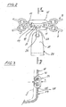
- FIG. 1 a tire 1 with its two flanks 3 is indicated schematically in dotted lines.
- an anti-skid device 7 On the tread 5 of the tire 1 is an anti-skid device 7, comprising two each partially parallel chain strands 9 of interconnected chain links 11. The two chain strands 9 are held by spacers 13 at a mutual distance.
- the two chain strands 9 are brought together on an intermediate member 15.
- the intermediate member 15 comprises an elongate recess 17, at the lateral ends of each a preferably round bore 19 and in the middle between the holes 19 an enlarged portion 21 are formed.
- each of the last chain links 11 of the two chain strands 9 are held.
- In section 21 engages a guide chain member 23, which is also mounted in a hole 25 at the free end 27 of a retaining clip 29 (see in particular FIG. 2 ).
- the guide chain link 23 is approximately perpendicular to the running direction L of the tire.
- the height h of the guide chain link which rests with its one flank on the tread 5 of the tire 1, is substantially equal to the height h of the chain links 11 of the chain strands 9, which also engage the intermediate member 15.
- the running away from the intermediate member 15 and connected to the intermediate member 15 chain links 11 is not shown.
- the headband 29 is connected in a known manner with its free end 27 opposite end, which is not shown, with the rotatably mounted on the wheel support ring.
- the guide chain link 23 Between the headband 29 and the chain mail formed from the two chain strands 9 and the spacer elements 13 is formed by the guide chain link 23, a hinged connection.
- the connection of the retaining clip 29 with two chain strands 9 also causes only small forces are exerted by the chain mail on the headband 29. in the more is ensured by the respective same height h of the guide chain link 23 and the chain links 11 of the armor on the tire tread 5 that even at the junction between headband 29 and the armor is a uniform support of the armor and the guide chain member 23 on the road.
- the wear of all chain links 11,15 is therefore always the same.
Landscapes
- Engineering & Computer Science (AREA)
- Mechanical Engineering (AREA)
- Tires In General (AREA)
- Surgical Instruments (AREA)
- Vehicle Body Suspensions (AREA)
- Chain Conveyers (AREA)
- Platform Screen Doors And Railroad Systems (AREA)
Description
- Gegenstand der Erfindung ist eine Gleitschutzvorrichtung für Fahrzeugräder gemäss Oberbegriff des Patenanspruchs 1. Gleitschutzvorrichtungen für Fahrzeugräder dienen einerseits im Winter als Schneeketten und andererseits können auch die Reifen von Arbeitsfahrzeugen mit Ketten ausgerüstet werden, um beispielsweise bei einer Benutzung in Steinbrüchen die Reifen vor vorzeitiger Zerstörung durch scharfkantige Steine zu schützen. Die vorliegende Erfindung bezieht sich insbesondere auf Gleitschutzvorrichtungen für die Benutzung im Schnee und/oder auf Eis. Bei der hier zur Diskussion stehenden Gleitschutzvorrichtung handelt es sich um eine solche, die mit sternförmig an einem Stützring angeordneten Armen, welcher an der Felge des Fahrzeugrades drehbar gehalten wird.
- Gleitschutzvorrichtungen der genannten Gattung sind bekannt.
- Aus der
US 4,799,522 ist eine gattungsbildende Gleitschutzvorrichtung für Fahrzeugräder bekannt, bei der auf der Reifenlauffläche ein leiterartiger Kettenpanzer angeordnet ist, welcher durch sternförmig mit dem Radzentrum verbundene Arme gehalten wird. An den freien Enden der Arme sind drahtförmige Bügel ausgebildet, welche mit den jeweils letzten Kettengliedern von Kettenabschnitten verbunden sind, welche den Kettenpanzer bilden. Die drahtförmigen Enden der Bügel müssen durch zusätzliche Umreifungen zusammengehalten werden, um die Zugkräfte der beiden Kettenstränge übernehmen zu können. Zudem sind die drahtförmigen Bügel einer dauernden dynamischen Belastung ausgesetzt, so dass die Gefahr von Drahtbrüchen die Sicherheit solcher Vorrichtungen in Frage stellt. - Eine Aufgabe der vorliegenden Erfindung ist die Schaffung einer Gleitschutzvorrichtung der genannten Gattung, welche die Nachteile der bekannten meidet und einen sehr einfachen, kostengünstig herstellbaren und weniger dem Verschleiss unterworfenen Aufbau aufweist.
- Gelöst wird diese Aufgabe durch eine Gleitschutzvorrichtung gemäss den Merkmalen des Patentanspruchs 1. Besonders vorteilhafte Ausgestaltungen sind in den abhängigen Ansprüchen umschrieben.
- Überraschenderweise gelingt es, durch eine frei bewegliche Verbindung zwischen einem Distanzstück, das die beiden Kettenstränge verbindet, und dem freien Ende des Haltebügels ohne radiale Vergrösserung des Durchmessers der Gleitschutzvorrichtung den Kettenpanzer exakt auf der Reifenlauffläche zu positionieren und zu führen.
- Anhand eines illustrierten Ausführungsbeispiels wird die Erfindung näher erläutert. Es zeigen:
- Figur 1
- eine Aufsicht auf eine auf einem Fahrzeugreifen aufgelegte Gleitschutzvorrichtung,
- Figur 2
- eine vergrösserte Darstellung der Verbindung zwischen Haltebügel und Kettenpanzer und
- Figur 3
- einen Schnitt längs Linie III-III in
Figur 2 durch die Verbindung. - In
Figur 1 ist in strichpunktierten Linien ein Reifen 1 mit seinen beiden Flanken 3 schematisch angedeutet. Auf der Lauffläche 5 des Reifens 1 liegt eine Gleitschutzvorrichtung 7, umfassend zwei jeweils abschnittsweise parallel verlaufende Kettenstränge 9 aus miteinander verbundenen Kettengliedern 11. Die beiden Kettenstränge 9 werden durch Distanzelemente 13 in gegenseitigem Abstand gehalten. - In regelmässigen Abständen, beispielsweise nach jeweils vier Distanzelementen werden die beiden Kettenstränge 9 auf ein Zwischenglied 15 zusammengeführt. Das Zwischenglied 15 umfasst eine längliche Ausnehmung 17, an deren seitlichen Enden jeweils eine vorzugsweise runde Bohrung 19 und in deren Mitte zwischen den Bohrungen 19 ein erweiterter Abschnitt 21 ausgebildet sind. In den beiden Bohrungen 19 werden jeweils die letzten Kettenglieder 11 der beiden Kettenstränge 9 gehalten. Im Abschnitt 21 greift ein Führungskettenglied 23 ein, welches zudem in einem Loch 25 am freien Ende 27 eines Haltebügels 29 angebracht ist (vergleiche insbesondere
Figur 2 ). Das Führungskettenglied 23 liegt etwa lotrecht zur Laufrichtung L des Reifens. Die Höhe h des Führungskettenglieds, welches mit seiner einen Flanke auf der Lauffläche 5 des Reifens 1 aufliegt, ist im wesentlichen gleich wie die Höhe h der Kettenglieder 11 der Kettenstränge 9, welche ebenfalls am Zwischenglied 15 angreifen. Der besseren Übersichtlichkeit halber sind inFigur 3 die vom Zwischenglied 15 weglaufenden und mit dem Zwischenglied 15 verbundenen Kettenglieder 11 nicht dargestellt. - Der Haltebügel 29 ist in bekannter Weise mit seinem dem freien Ende 27 gegenüber liegenden Ende, das nicht dargestellt ist, mit dem am Rad drehbar befestigten Stützring verbunden.
- Zwischen dem Haltebügel 29 und dem aus den beiden Kettensträngen 9 und den Distanzelementen 13 gebildeten Kettenpanzer entsteht durch das Führungskettenglied 23 eine gelenkige Verbindung. Dadurch dass das Zwischenglied 15 jeweils die beiden Kettenstränge 9 zusammenfasst, wird der Kettenpanzer, obwohl gelenkig mit dem Haltebügel 29 verbunden, präzise geführt. D.h. die beiden Kettenstränge 9 können sich in Laufrichtung L relativ zueinander nicht verschieben. Die Verbindung des Haltebügels 29 mit beiden Kettensträngen 9 bewirkt auch, dass nur geringe Kräfte vom Kettenpanzer auf die Haltebügel 29 ausgeübt werden. Im weiteren ist durch die jeweils gleiche Höhe h des Führungskettenglieds 23 sowie der Kettenglieder 11 des Kettenpanzers über der Reifenlauffläche 5 gewährleistet, dass auch an der Verbindungsstelle zwischen Haltebügel 29 und dem Kettenpanzer eine gleichmässige Auflage des Kettenpanzers und des Führungskettenglieds 23 auf der Fahrbahn erfolgt. Die Abnützung aller Kettenglieder 11,15 ist demzufolge stets gleich. Durch Verwendung eines offenen Führungskettenglieds 23, wie in gebrochenen Linien in
Figur 3 angedeutet, kann der Kettenpanzer von den Haltebügeln 29 gelöst und gewendet werden, sobald ein entsprechender Verschleiss eingetreten ist.
Claims (6)
- Gleitschutzvorrichtung für Fahrzeugräder, umfassend einen Kettenpanzer mit zwei ringförmigen, im wesentlichen in Reifenumfangsrichtung (L) auf der Reifenlauffläche (5) aufzuliegen bestimmten und den Reifen (1) umschlingende Kettensträngen (9), welche durch Distanzelemente (13) in einem gegenseitigen Abstand gehalten werden, sowie sternförmig auf einem drehbaren Stützring am Fahrzeugrad befestigte Haltebügel (29), deren freie Enden (27) mit je einem die beiden Kettenstränge (9) verbindenden Zwischenglied (15) verbunden sind, dadurch gekennzeichnet, dass das Zwischenglied (15) zwischen den beiden Kettensträngen (9) liegt und dass zwischen dem Zwischenglied (15) und dem freien Ende (27) der Haltebügel (29) ein Führungskettenglied (23) eingesetzt ist, welches den Haltebügel (29) und das Zwischenglied (15) gelenkig miteinander verbindet, derart, dass keine Wechsellasten vom Zwischenglied (15) auf die Haltebügel (29) übertragbar sind.
- Gleitschutzvorrichtung nach Anspruch 1, dadurch gekennzeichnet, dass die Zwischenglieder (15) die Kettenstränge (9) kreuzförmig zusammenhalten.
- Gleitschutzvorrichtung nach Anspruch 1, dadurch gekennzeichnet, dass die Zwischenglieder (15) eine Platte mit zwei beabstandet angebrachten Bohrungen (19) umfassen, in welche jeweils die letzten Kettenglieder (11) der beiden Kettenstränge (9) gehalten sind.
- Gleitschutzvorrichtung nach Anspruch 3, dadurch gekennzeichnet, dass die Führungskettenglieder (23) in einer an der Platte angebrachten Ausnehmung (17) und einem Loch (25) am Ende (27) der Haltebügel (29) gehalten werden.
- Gleitschutzvorrichtung nach einem der Ansprüche 1 bis 4, dadurch gekennzeichnet, dass die Führungskettenglieder (23) in sich geschlossen oder offen sind.
- Gleitschutzvorrichtung nach einem der Ansprüche 1 bis 5, dadurch gekennzeichnet, dass die Höhe (h) der Führungskettenglieder (23) der Höhe (h) der Kettenglieder (11) der Kettenstränge (9) entspricht.
Applications Claiming Priority (2)
| Application Number | Priority Date | Filing Date | Title |
|---|---|---|---|
| CH15452004 | 2004-09-21 | ||
| PCT/CH2005/000514 WO2006032155A1 (de) | 2004-09-21 | 2005-09-01 | Gleitschutzvorrichtung für fahrzeugräder |
Publications (2)
| Publication Number | Publication Date |
|---|---|
| EP1791704A1 EP1791704A1 (de) | 2007-06-06 |
| EP1791704B1 true EP1791704B1 (de) | 2009-07-08 |
Family
ID=35229616
Family Applications (1)
| Application Number | Title | Priority Date | Filing Date |
|---|---|---|---|
| EP05773738A Expired - Lifetime EP1791704B1 (de) | 2004-09-21 | 2005-09-01 | Gleitschutzvorrichtung für fahrzeugräder |
Country Status (8)
| Country | Link |
|---|---|
| US (1) | US7578326B2 (de) |
| EP (1) | EP1791704B1 (de) |
| JP (1) | JP2008513262A (de) |
| KR (1) | KR20070055548A (de) |
| AT (1) | ATE435765T1 (de) |
| DE (1) | DE502005007668D1 (de) |
| RU (1) | RU2376154C2 (de) |
| WO (1) | WO2006032155A1 (de) |
Families Citing this family (6)
| Publication number | Priority date | Publication date | Assignee | Title |
|---|---|---|---|---|
| US9233584B2 (en) | 2010-08-16 | 2016-01-12 | J. Scott Hanson | Tire chain and method of modifying a tire chain |
| DE102011003124A1 (de) | 2011-01-25 | 2012-07-26 | Rud Ketten Rieger & Dietz Gmbh U. Co. Kg | Verkürzungselement für Reifenketten und Reifenkette |
| USD991157S1 (en) * | 2021-06-17 | 2023-07-04 | Guolin Pei | Tire chain |
| USD1020617S1 (en) * | 2022-08-01 | 2024-04-02 | Shenzhen Putong E-Commerce Co., Ltd. | Car tire chain |
| USD1051031S1 (en) * | 2023-04-11 | 2024-11-12 | Enqi Zheng | Snow chain |
| USD1051033S1 (en) * | 2023-05-19 | 2024-11-12 | Han Zheng | Snow chain |
Family Cites Families (16)
| Publication number | Priority date | Publication date | Assignee | Title |
|---|---|---|---|---|
| US1368175A (en) * | 1920-05-21 | 1921-02-08 | William E Mcfee | Connecting-link |
| US3095919A (en) * | 1961-02-20 | 1963-07-02 | Lester N Yohe | Traction device |
| DE7732129U1 (de) * | 1977-10-18 | 1978-02-09 | Fa. August Thiele, 5860 Iserlohn | Schliessvorrichtung fuer die seitenketten von gleitschutzketten offener bauart mit einer verschlusshakenanordnung |
| SE436257B (sv) * | 1980-10-29 | 1984-11-26 | Ilon B E | Anordning vid slirskydd for hjul |
| DE3545529A1 (de) * | 1985-12-20 | 1987-07-02 | Autotyp Sa | Schneekette fuer fahrzeugraeder |
| DE8709545U1 (de) * | 1987-07-08 | 1987-10-29 | Rud-Kettenfabrik Rieger & Dietz Gmbh U. Co, 7080 Aalen | Zusammenlegbare Gleitschutzvorrichtung für Fahrzeugräder |
| DE3774709D1 (de) * | 1987-10-22 | 1992-01-02 | Autotyp Sa | Gleitschutzvorrichtung fuer raeder. |
| DE3735827A1 (de) * | 1987-10-22 | 1989-05-03 | Autotyp Sa | Gleitschutzvorrichtung fuer raeder, insbesondere raeder fuer lastkraftwagen |
| CH676828A5 (de) * | 1988-07-13 | 1991-03-15 | Autotyp Sa | |
| DE3844494A1 (de) * | 1988-12-30 | 1990-07-05 | Rud Ketten Rieger & Dietz | Gleitschutzvorrichtung |
| DE3844496A1 (de) * | 1988-12-30 | 1990-07-05 | Rud Ketten Rieger & Dietz | Gleitschutzvorrichtung fuer fahrzeugraeder |
| DE3906486A1 (de) * | 1989-03-01 | 1990-09-13 | Weissenfels Contiweiss | Gleitschutzkette |
| DE4018415C1 (en) * | 1990-06-06 | 1991-10-17 | Rud-Kettenfabrik Rieger & Dietz Gmbh U. Co, 7080 Aalen, De | Antiskid cover on vehicle wheel - incorporates retaining member with arms engaging links on chain |
| CH685046A5 (fr) * | 1991-01-24 | 1995-03-15 | Autotyp Sa | Dispositif antidérapant pour roue de véhicule. |
| DE19748942C2 (de) * | 1997-10-24 | 2000-01-05 | Rud Ketten Rieger & Dietz | Gleitschutzvorrichtung |
| DE10137512C1 (de) * | 2001-07-26 | 2003-03-27 | Rud Ketten Rieger & Dietz | Gleitschutzvorrichtung für Fahrzeugräder |
-
2005
- 2005-09-01 RU RU2007115094/11A patent/RU2376154C2/ru not_active IP Right Cessation
- 2005-09-01 WO PCT/CH2005/000514 patent/WO2006032155A1/de not_active Ceased
- 2005-09-01 EP EP05773738A patent/EP1791704B1/de not_active Expired - Lifetime
- 2005-09-01 US US11/574,461 patent/US7578326B2/en not_active Expired - Fee Related
- 2005-09-01 AT AT05773738T patent/ATE435765T1/de not_active IP Right Cessation
- 2005-09-01 JP JP2007531563A patent/JP2008513262A/ja active Pending
- 2005-09-01 DE DE502005007668T patent/DE502005007668D1/de not_active Expired - Lifetime
- 2005-09-01 KR KR1020077006415A patent/KR20070055548A/ko not_active Ceased
Also Published As
| Publication number | Publication date |
|---|---|
| RU2376154C2 (ru) | 2009-12-20 |
| KR20070055548A (ko) | 2007-05-30 |
| DE502005007668D1 (de) | 2009-08-20 |
| US7578326B2 (en) | 2009-08-25 |
| WO2006032155A1 (de) | 2006-03-30 |
| EP1791704A1 (de) | 2007-06-06 |
| RU2007115094A (ru) | 2008-10-27 |
| JP2008513262A (ja) | 2008-05-01 |
| US20080190533A1 (en) | 2008-08-14 |
| ATE435765T1 (de) | 2009-07-15 |
Similar Documents
| Publication | Publication Date | Title |
|---|---|---|
| EP0298905B2 (de) | Gleitschutzvorrichtung für Fahrzeugräder | |
| DE602006000809T2 (de) | Schneekette mit Strängen von gewundenen Kettengliedern | |
| EP2172351B1 (de) | Kettenglied für Gleitschutzkette | |
| EP1791704A1 (de) | Gleitschutzvorrichtung für fahrzeugräder | |
| EP1711356A1 (de) | Vorrichtung zum werkzeugfreien verstellbaren verbinden zweier kettenglieder einer geschlossenen gliederkette in unterschiedlichen abständen und/oder reparieren einer gebrochenen gliederkette | |
| EP0460782B1 (de) | Gleitschutzvorrichtung | |
| DE102009050078A1 (de) | Kettenverbindungsglied | |
| EP3216629A1 (de) | Gleitschutzvorrichtung mit schräg aufliegender rund- oder profilstahlkette | |
| DE19813831C1 (de) | Gleitschutzvorrichtung | |
| EP3339064B1 (de) | Kettenglied mit reibverschweisstem traktionselement, verfahren zu seiner herstellung und gleitschutz- oder reifenschutzvorrichtung mit einem solchen kettenglied | |
| EP2033815A2 (de) | Gliederverband für eine Reifenkette mit einem Verschleissglied | |
| DE19844408C1 (de) | Radspannersystem für Nachspanneinrichtungen von Fahrdrähten und Tragseilen einer Kettenwerk-Oberleitungsanlage | |
| DE8127446U1 (de) | Gleitschutzkette fuer fahrzeugreifen | |
| DE102019005981B3 (de) | Flexibler Verbinder für Kettenelemente einer Gleiskette | |
| EP1355792A1 (de) | Reifenkette | |
| EP1534543A1 (de) | Gleitschutzkette | |
| DE2728790C2 (de) | ||
| DE19702815C1 (de) | Gleitschutzkette | |
| DE2910084A1 (de) | Gleitschutzkette fuer fahrzeugreifen | |
| DE102008008807B3 (de) | Förderkette | |
| EP0084580B1 (de) | Reifen- und Gleitschutzkette | |
| EP3994052B1 (de) | Gleitschutzkette mit verdrehsperre ziwschen benachbarten kettengliedern | |
| EP4684985A1 (de) | Laufnetz, gleitschutzvorrichtung und laufnetzelement mit wenigstens einem von einem kunststoffkörper umspritzten laufnetzelement | |
| DE305818C (de) | ||
| EP0554530A1 (de) | Kettenglied für den Gleitschutz eines Fahrzeugrades |
Legal Events
| Date | Code | Title | Description |
|---|---|---|---|
| PUAI | Public reference made under article 153(3) epc to a published international application that has entered the european phase |
Free format text: ORIGINAL CODE: 0009012 |
|
| 17P | Request for examination filed |
Effective date: 20070120 |
|
| AK | Designated contracting states |
Kind code of ref document: A1 Designated state(s): AT BE BG CH CY CZ DE DK EE ES FI FR GB GR HU IE IS IT LI LT LU LV MC NL PL PT RO SE SI SK TR |
|
| DAX | Request for extension of the european patent (deleted) | ||
| 17Q | First examination report despatched |
Effective date: 20080813 |
|
| GRAP | Despatch of communication of intention to grant a patent |
Free format text: ORIGINAL CODE: EPIDOSNIGR1 |
|
| GRAS | Grant fee paid |
Free format text: ORIGINAL CODE: EPIDOSNIGR3 |
|
| GRAA | (expected) grant |
Free format text: ORIGINAL CODE: 0009210 |
|
| AK | Designated contracting states |
Kind code of ref document: B1 Designated state(s): AT BE BG CH CY CZ DE DK EE ES FI FR GB GR HU IE IS IT LI LT LU LV MC NL PL PT RO SE SI SK TR |
|
| REG | Reference to a national code |
Ref country code: GB Ref legal event code: FG4D Free format text: NOT ENGLISH |
|
| REG | Reference to a national code |
Ref country code: CH Ref legal event code: EP |
|
| REG | Reference to a national code |
Ref country code: IE Ref legal event code: FG4D |
|
| REF | Corresponds to: |
Ref document number: 502005007668 Country of ref document: DE Date of ref document: 20090820 Kind code of ref document: P |
|
| REG | Reference to a national code |
Ref country code: CH Ref legal event code: NV Representative=s name: HANS RUDOLF GACHNANG PATENTANWALT |
|
| PG25 | Lapsed in a contracting state [announced via postgrant information from national office to epo] |
Ref country code: SI Free format text: LAPSE BECAUSE OF FAILURE TO SUBMIT A TRANSLATION OF THE DESCRIPTION OR TO PAY THE FEE WITHIN THE PRESCRIBED TIME-LIMIT Effective date: 20090708 |
|
| NLV1 | Nl: lapsed or annulled due to failure to fulfill the requirements of art. 29p and 29m of the patents act | ||
| PG25 | Lapsed in a contracting state [announced via postgrant information from national office to epo] |
Ref country code: FI Free format text: LAPSE BECAUSE OF FAILURE TO SUBMIT A TRANSLATION OF THE DESCRIPTION OR TO PAY THE FEE WITHIN THE PRESCRIBED TIME-LIMIT Effective date: 20090708 Ref country code: IS Free format text: LAPSE BECAUSE OF FAILURE TO SUBMIT A TRANSLATION OF THE DESCRIPTION OR TO PAY THE FEE WITHIN THE PRESCRIBED TIME-LIMIT Effective date: 20091108 Ref country code: ES Free format text: LAPSE BECAUSE OF FAILURE TO SUBMIT A TRANSLATION OF THE DESCRIPTION OR TO PAY THE FEE WITHIN THE PRESCRIBED TIME-LIMIT Effective date: 20091019 Ref country code: LT Free format text: LAPSE BECAUSE OF FAILURE TO SUBMIT A TRANSLATION OF THE DESCRIPTION OR TO PAY THE FEE WITHIN THE PRESCRIBED TIME-LIMIT Effective date: 20090708 |
|
| REG | Reference to a national code |
Ref country code: IE Ref legal event code: FD4D |
|
| PG25 | Lapsed in a contracting state [announced via postgrant information from national office to epo] |
Ref country code: NL Free format text: LAPSE BECAUSE OF FAILURE TO SUBMIT A TRANSLATION OF THE DESCRIPTION OR TO PAY THE FEE WITHIN THE PRESCRIBED TIME-LIMIT Effective date: 20090708 Ref country code: PL Free format text: LAPSE BECAUSE OF FAILURE TO SUBMIT A TRANSLATION OF THE DESCRIPTION OR TO PAY THE FEE WITHIN THE PRESCRIBED TIME-LIMIT Effective date: 20090708 Ref country code: LV Free format text: LAPSE BECAUSE OF FAILURE TO SUBMIT A TRANSLATION OF THE DESCRIPTION OR TO PAY THE FEE WITHIN THE PRESCRIBED TIME-LIMIT Effective date: 20090708 |
|
| BERE | Be: lapsed |
Owner name: CONFON A.G. Effective date: 20090930 |
|
| PG25 | Lapsed in a contracting state [announced via postgrant information from national office to epo] |
Ref country code: PT Free format text: LAPSE BECAUSE OF FAILURE TO SUBMIT A TRANSLATION OF THE DESCRIPTION OR TO PAY THE FEE WITHIN THE PRESCRIBED TIME-LIMIT Effective date: 20091109 Ref country code: BG Free format text: LAPSE BECAUSE OF FAILURE TO SUBMIT A TRANSLATION OF THE DESCRIPTION OR TO PAY THE FEE WITHIN THE PRESCRIBED TIME-LIMIT Effective date: 20091008 |
|
| PG25 | Lapsed in a contracting state [announced via postgrant information from national office to epo] |
Ref country code: RO Free format text: LAPSE BECAUSE OF FAILURE TO SUBMIT A TRANSLATION OF THE DESCRIPTION OR TO PAY THE FEE WITHIN THE PRESCRIBED TIME-LIMIT Effective date: 20090708 Ref country code: MC Free format text: LAPSE BECAUSE OF NON-PAYMENT OF DUE FEES Effective date: 20090930 Ref country code: CZ Free format text: LAPSE BECAUSE OF FAILURE TO SUBMIT A TRANSLATION OF THE DESCRIPTION OR TO PAY THE FEE WITHIN THE PRESCRIBED TIME-LIMIT Effective date: 20090708 Ref country code: DK Free format text: LAPSE BECAUSE OF FAILURE TO SUBMIT A TRANSLATION OF THE DESCRIPTION OR TO PAY THE FEE WITHIN THE PRESCRIBED TIME-LIMIT Effective date: 20090708 Ref country code: IE Free format text: LAPSE BECAUSE OF FAILURE TO SUBMIT A TRANSLATION OF THE DESCRIPTION OR TO PAY THE FEE WITHIN THE PRESCRIBED TIME-LIMIT Effective date: 20090708 Ref country code: EE Free format text: LAPSE BECAUSE OF FAILURE TO SUBMIT A TRANSLATION OF THE DESCRIPTION OR TO PAY THE FEE WITHIN THE PRESCRIBED TIME-LIMIT Effective date: 20090708 |
|
| PLBE | No opposition filed within time limit |
Free format text: ORIGINAL CODE: 0009261 |
|
| STAA | Information on the status of an ep patent application or granted ep patent |
Free format text: STATUS: NO OPPOSITION FILED WITHIN TIME LIMIT |
|
| PG25 | Lapsed in a contracting state [announced via postgrant information from national office to epo] |
Ref country code: SK Free format text: LAPSE BECAUSE OF FAILURE TO SUBMIT A TRANSLATION OF THE DESCRIPTION OR TO PAY THE FEE WITHIN THE PRESCRIBED TIME-LIMIT Effective date: 20090708 |
|
| 26N | No opposition filed |
Effective date: 20100409 |
|
| REG | Reference to a national code |
Ref country code: FR Ref legal event code: ST Effective date: 20100531 |
|
| PG25 | Lapsed in a contracting state [announced via postgrant information from national office to epo] |
Ref country code: FR Free format text: LAPSE BECAUSE OF NON-PAYMENT OF DUE FEES Effective date: 20090930 |
|
| PG25 | Lapsed in a contracting state [announced via postgrant information from national office to epo] |
Ref country code: BE Free format text: LAPSE BECAUSE OF NON-PAYMENT OF DUE FEES Effective date: 20090930 |
|
| PG25 | Lapsed in a contracting state [announced via postgrant information from national office to epo] |
Ref country code: GR Free format text: LAPSE BECAUSE OF FAILURE TO SUBMIT A TRANSLATION OF THE DESCRIPTION OR TO PAY THE FEE WITHIN THE PRESCRIBED TIME-LIMIT Effective date: 20091009 |
|
| PG25 | Lapsed in a contracting state [announced via postgrant information from national office to epo] |
Ref country code: AT Free format text: LAPSE BECAUSE OF NON-PAYMENT OF DUE FEES Effective date: 20090901 Ref country code: GB Free format text: LAPSE BECAUSE OF NON-PAYMENT OF DUE FEES Effective date: 20091008 |
|
| PG25 | Lapsed in a contracting state [announced via postgrant information from national office to epo] |
Ref country code: IT Free format text: LAPSE BECAUSE OF FAILURE TO SUBMIT A TRANSLATION OF THE DESCRIPTION OR TO PAY THE FEE WITHIN THE PRESCRIBED TIME-LIMIT Effective date: 20090708 |
|
| PG25 | Lapsed in a contracting state [announced via postgrant information from national office to epo] |
Ref country code: LU Free format text: LAPSE BECAUSE OF NON-PAYMENT OF DUE FEES Effective date: 20090901 |
|
| PG25 | Lapsed in a contracting state [announced via postgrant information from national office to epo] |
Ref country code: HU Free format text: LAPSE BECAUSE OF FAILURE TO SUBMIT A TRANSLATION OF THE DESCRIPTION OR TO PAY THE FEE WITHIN THE PRESCRIBED TIME-LIMIT Effective date: 20100109 |
|
| PG25 | Lapsed in a contracting state [announced via postgrant information from national office to epo] |
Ref country code: TR Free format text: LAPSE BECAUSE OF FAILURE TO SUBMIT A TRANSLATION OF THE DESCRIPTION OR TO PAY THE FEE WITHIN THE PRESCRIBED TIME-LIMIT Effective date: 20090708 |
|
| PG25 | Lapsed in a contracting state [announced via postgrant information from national office to epo] |
Ref country code: CY Free format text: LAPSE BECAUSE OF FAILURE TO SUBMIT A TRANSLATION OF THE DESCRIPTION OR TO PAY THE FEE WITHIN THE PRESCRIBED TIME-LIMIT Effective date: 20090708 |
|
| PG25 | Lapsed in a contracting state [announced via postgrant information from national office to epo] |
Ref country code: SE Free format text: LAPSE BECAUSE OF FAILURE TO SUBMIT A TRANSLATION OF THE DESCRIPTION OR TO PAY THE FEE WITHIN THE PRESCRIBED TIME-LIMIT Effective date: 20090708 |
|
| REG | Reference to a national code |
Ref country code: CH Ref legal event code: NV Representative=s name: GACHNANG AG PATENTANWAELTE, CH |
|
| PGFP | Annual fee paid to national office [announced via postgrant information from national office to epo] |
Ref country code: DE Payment date: 20140812 Year of fee payment: 10 |
|
| REG | Reference to a national code |
Ref country code: DE Ref legal event code: R119 Ref document number: 502005007668 Country of ref document: DE |
|
| PG25 | Lapsed in a contracting state [announced via postgrant information from national office to epo] |
Ref country code: DE Free format text: LAPSE BECAUSE OF NON-PAYMENT OF DUE FEES Effective date: 20160401 |
|
| PGFP | Annual fee paid to national office [announced via postgrant information from national office to epo] |
Ref country code: CH Payment date: 20160919 Year of fee payment: 12 |
|
| REG | Reference to a national code |
Ref country code: CH Ref legal event code: PL |
|
| PG25 | Lapsed in a contracting state [announced via postgrant information from national office to epo] |
Ref country code: CH Free format text: LAPSE BECAUSE OF NON-PAYMENT OF DUE FEES Effective date: 20170930 Ref country code: LI Free format text: LAPSE BECAUSE OF NON-PAYMENT OF DUE FEES Effective date: 20170930 |