EP1791476B1 - Appareil de suture a invasivite minimale - Google Patents
Appareil de suture a invasivite minimale Download PDFInfo
- Publication number
- EP1791476B1 EP1791476B1 EP05797831.4A EP05797831A EP1791476B1 EP 1791476 B1 EP1791476 B1 EP 1791476B1 EP 05797831 A EP05797831 A EP 05797831A EP 1791476 B1 EP1791476 B1 EP 1791476B1
- Authority
- EP
- European Patent Office
- Prior art keywords
- needle
- suturing
- head assembly
- suture head
- suturing device
- Prior art date
- Legal status (The legal status is an assumption and is not a legal conclusion. Google has not performed a legal analysis and makes no representation as to the accuracy of the status listed.)
- Active
Links
- 230000007246 mechanism Effects 0.000 claims description 80
- 238000004140 cleaning Methods 0.000 claims description 3
- 239000012530 fluid Substances 0.000 claims description 2
- 210000001519 tissue Anatomy 0.000 description 95
- 239000003356 suture material Substances 0.000 description 35
- 238000000034 method Methods 0.000 description 34
- 238000002324 minimally invasive surgery Methods 0.000 description 15
- 238000001356 surgical procedure Methods 0.000 description 10
- 239000000463 material Substances 0.000 description 8
- 230000001681 protective effect Effects 0.000 description 7
- 230000008901 benefit Effects 0.000 description 6
- 238000002591 computed tomography Methods 0.000 description 6
- 230000008439 repair process Effects 0.000 description 6
- 241001631457 Cannula Species 0.000 description 5
- 230000009471 action Effects 0.000 description 5
- 230000003213 activating effect Effects 0.000 description 5
- 238000013461 design Methods 0.000 description 5
- 239000007789 gas Substances 0.000 description 5
- 238000002357 laparoscopic surgery Methods 0.000 description 5
- 239000007769 metal material Substances 0.000 description 5
- CURLTUGMZLYLDI-UHFFFAOYSA-N Carbon dioxide Chemical compound O=C=O CURLTUGMZLYLDI-UHFFFAOYSA-N 0.000 description 4
- RTAQQCXQSZGOHL-UHFFFAOYSA-N Titanium Chemical compound [Ti] RTAQQCXQSZGOHL-UHFFFAOYSA-N 0.000 description 4
- 210000001015 abdomen Anatomy 0.000 description 4
- 238000004873 anchoring Methods 0.000 description 4
- 230000000740 bleeding effect Effects 0.000 description 4
- 208000015181 infectious disease Diseases 0.000 description 4
- 238000002595 magnetic resonance imaging Methods 0.000 description 4
- 230000008569 process Effects 0.000 description 4
- 229910001220 stainless steel Inorganic materials 0.000 description 4
- 239000010935 stainless steel Substances 0.000 description 4
- 230000001954 sterilising effect Effects 0.000 description 4
- 238000004659 sterilization and disinfection Methods 0.000 description 4
- 229910052719 titanium Inorganic materials 0.000 description 4
- 239000010936 titanium Substances 0.000 description 4
- 238000012800 visualization Methods 0.000 description 4
- 230000003993 interaction Effects 0.000 description 3
- 230000013011 mating Effects 0.000 description 3
- 230000036316 preload Effects 0.000 description 3
- 210000001835 viscera Anatomy 0.000 description 3
- 206010060954 Abdominal Hernia Diseases 0.000 description 2
- IJGRMHOSHXDMSA-UHFFFAOYSA-N Atomic nitrogen Chemical compound N#N IJGRMHOSHXDMSA-UHFFFAOYSA-N 0.000 description 2
- 208000034991 Hiatal Hernia Diseases 0.000 description 2
- 208000029836 Inguinal Hernia Diseases 0.000 description 2
- 206010041101 Small intestinal obstruction Diseases 0.000 description 2
- 208000035091 Ventral Hernia Diseases 0.000 description 2
- 230000003872 anastomosis Effects 0.000 description 2
- 210000001367 artery Anatomy 0.000 description 2
- 239000012237 artificial material Substances 0.000 description 2
- 244000052616 bacterial pathogen Species 0.000 description 2
- 229910002092 carbon dioxide Inorganic materials 0.000 description 2
- 239000001569 carbon dioxide Substances 0.000 description 2
- 238000012321 colectomy Methods 0.000 description 2
- 238000010276 construction Methods 0.000 description 2
- 238000002788 crimping Methods 0.000 description 2
- 210000003195 fascia Anatomy 0.000 description 2
- 239000000446 fuel Substances 0.000 description 2
- 238000013110 gastrectomy Methods 0.000 description 2
- 230000002496 gastric effect Effects 0.000 description 2
- 210000004185 liver Anatomy 0.000 description 2
- 238000013059 nephrectomy Methods 0.000 description 2
- JCXJVPUVTGWSNB-UHFFFAOYSA-N nitrogen dioxide Inorganic materials O=[N]=O JCXJVPUVTGWSNB-UHFFFAOYSA-N 0.000 description 2
- 238000002271 resection Methods 0.000 description 2
- 210000004872 soft tissue Anatomy 0.000 description 2
- 238000010911 splenectomy Methods 0.000 description 2
- 238000010408 sweeping Methods 0.000 description 2
- 210000003462 vein Anatomy 0.000 description 2
- 0 C=*1CI*C1 Chemical compound C=*1CI*C1 0.000 description 1
- 239000004215 Carbon black (E152) Substances 0.000 description 1
- 206010069803 Injury associated with device Diseases 0.000 description 1
- 208000012266 Needlestick injury Diseases 0.000 description 1
- 241000700605 Viruses Species 0.000 description 1
- 206010052428 Wound Diseases 0.000 description 1
- 208000027418 Wounds and injury Diseases 0.000 description 1
- 210000000436 anus Anatomy 0.000 description 1
- 230000009286 beneficial effect Effects 0.000 description 1
- 210000004204 blood vessel Anatomy 0.000 description 1
- 238000007796 conventional method Methods 0.000 description 1
- 238000002674 endoscopic surgery Methods 0.000 description 1
- 210000003238 esophagus Anatomy 0.000 description 1
- 210000004247 hand Anatomy 0.000 description 1
- 229930195733 hydrocarbon Natural products 0.000 description 1
- 150000002430 hydrocarbons Chemical class 0.000 description 1
- 238000003384 imaging method Methods 0.000 description 1
- 238000003780 insertion Methods 0.000 description 1
- 230000037431 insertion Effects 0.000 description 1
- 238000012977 invasive surgical procedure Methods 0.000 description 1
- 238000004519 manufacturing process Methods 0.000 description 1
- 210000000056 organ Anatomy 0.000 description 1
- 239000005022 packaging material Substances 0.000 description 1
- 230000000149 penetrating effect Effects 0.000 description 1
- 230000035515 penetration Effects 0.000 description 1
- 238000003825 pressing Methods 0.000 description 1
- 230000002040 relaxant effect Effects 0.000 description 1
- 239000007787 solid Substances 0.000 description 1
- 230000001360 synchronised effect Effects 0.000 description 1
- 210000001215 vagina Anatomy 0.000 description 1
- 238000003466 welding Methods 0.000 description 1
- 210000000707 wrist Anatomy 0.000 description 1
Images


Classifications
-
- A—HUMAN NECESSITIES
- A61—MEDICAL OR VETERINARY SCIENCE; HYGIENE
- A61B—DIAGNOSIS; SURGERY; IDENTIFICATION
- A61B17/00—Surgical instruments, devices or methods, e.g. tourniquets
- A61B17/04—Surgical instruments, devices or methods, e.g. tourniquets for suturing wounds; Holders or packages for needles or suture materials
- A61B17/0482—Needle or suture guides
-
- A—HUMAN NECESSITIES
- A61—MEDICAL OR VETERINARY SCIENCE; HYGIENE
- A61B—DIAGNOSIS; SURGERY; IDENTIFICATION
- A61B17/00—Surgical instruments, devices or methods, e.g. tourniquets
- A61B17/04—Surgical instruments, devices or methods, e.g. tourniquets for suturing wounds; Holders or packages for needles or suture materials
- A61B17/06—Needles ; Sutures; Needle-suture combinations; Holders or packages for needles or suture materials
- A61B17/062—Needle manipulators
- A61B17/0625—Needle manipulators the needle being specially adapted to interact with the manipulator, e.g. being ridged to snap fit in a hole of the manipulator
-
- A—HUMAN NECESSITIES
- A61—MEDICAL OR VETERINARY SCIENCE; HYGIENE
- A61B—DIAGNOSIS; SURGERY; IDENTIFICATION
- A61B17/00—Surgical instruments, devices or methods, e.g. tourniquets
- A61B17/04—Surgical instruments, devices or methods, e.g. tourniquets for suturing wounds; Holders or packages for needles or suture materials
- A61B17/0469—Suturing instruments for use in minimally invasive surgery, e.g. endoscopic surgery
-
- A—HUMAN NECESSITIES
- A61—MEDICAL OR VETERINARY SCIENCE; HYGIENE
- A61B—DIAGNOSIS; SURGERY; IDENTIFICATION
- A61B17/00—Surgical instruments, devices or methods, e.g. tourniquets
- A61B17/04—Surgical instruments, devices or methods, e.g. tourniquets for suturing wounds; Holders or packages for needles or suture materials
- A61B17/06—Needles ; Sutures; Needle-suture combinations; Holders or packages for needles or suture materials
- A61B17/06066—Needles, e.g. needle tip configurations
-
- A—HUMAN NECESSITIES
- A61—MEDICAL OR VETERINARY SCIENCE; HYGIENE
- A61B—DIAGNOSIS; SURGERY; IDENTIFICATION
- A61B17/00—Surgical instruments, devices or methods, e.g. tourniquets
- A61B17/04—Surgical instruments, devices or methods, e.g. tourniquets for suturing wounds; Holders or packages for needles or suture materials
- A61B17/06—Needles ; Sutures; Needle-suture combinations; Holders or packages for needles or suture materials
- A61B17/06004—Means for attaching suture to needle
- A61B2017/06028—Means for attaching suture to needle by means of a cylindrical longitudinal blind bore machined at the suture-receiving end of the needle, e.g. opposite to needle tip
-
- A—HUMAN NECESSITIES
- A61—MEDICAL OR VETERINARY SCIENCE; HYGIENE
- A61B—DIAGNOSIS; SURGERY; IDENTIFICATION
- A61B17/00—Surgical instruments, devices or methods, e.g. tourniquets
- A61B17/28—Surgical forceps
- A61B17/29—Forceps for use in minimally invasive surgery
- A61B17/2909—Handles
- A61B2017/2912—Handles transmission of forces to actuating rod or piston
- A61B2017/2923—Toothed members, e.g. rack and pinion
-
- A—HUMAN NECESSITIES
- A61—MEDICAL OR VETERINARY SCIENCE; HYGIENE
- A61B—DIAGNOSIS; SURGERY; IDENTIFICATION
- A61B17/00—Surgical instruments, devices or methods, e.g. tourniquets
- A61B17/28—Surgical forceps
- A61B17/29—Forceps for use in minimally invasive surgery
- A61B2017/2926—Details of heads or jaws
- A61B2017/2927—Details of heads or jaws the angular position of the head being adjustable with respect to the shaft
-
- A—HUMAN NECESSITIES
- A61—MEDICAL OR VETERINARY SCIENCE; HYGIENE
- A61B—DIAGNOSIS; SURGERY; IDENTIFICATION
- A61B17/00—Surgical instruments, devices or methods, e.g. tourniquets
- A61B17/28—Surgical forceps
- A61B17/29—Forceps for use in minimally invasive surgery
- A61B2017/2926—Details of heads or jaws
- A61B2017/2932—Transmission of forces to jaw members
- A61B2017/2943—Toothed members, e.g. rack and pinion
Definitions
- the embodiments disclosed herein relate to a medical device for suturing tissue, and more particularly to a device for the manipulation and control of a suturing needle during minimally invasive suturing.
- MIS Minimally invasive surgery
- keyhole surgery a small punctures
- natural orifices including the vagina, the esophagus, or the anus.
- a small puncture is typically made in the body. Medical instruments are then inserted through a cannula.
- a cannula has a small inside diameter, typically 5-10 millimeters (mm), and sometimes up to 20 millimeters (mm) or more. A number of such cannulas are inserted into the body for any given operation. Minimally invasive surgical instruments are necessarily smaller, and are also generally longer and therefore are more difficult to manipulate with precision.
- Suturing requires coordinated manipulation with both hands of small needles and sutures that are difficult to visualize (particularly when only indirect, two-dimensional video imaging is available) as well as the several instruments (including needle-drivers and pick-up forceps) ordinarily used to suture by hand.
- several instruments including needle-drivers and pick-up forceps ordinarily used to suture by hand.
- many surgeons find minimally invasive suturing by hand an extremely difficult, often virtually impossible, surgical task.
- a grasping forceps (“needle driver”) is held by the surgeon and is used to grip a curved needle near the needle's tail. Pronation of the surgeon's wrist drives the needle into the tissue. When the point of the curved needle emerges from the tissue, the surgeon releases the needle from the grip of the needle driver and grasps the point with another forceps ("pick-ups"). The surgeon then pulls the curved needle by the needle point, preferably in a circular path following the arc of the needle's curvature to follow the most atraumatic path through the tissue, until the entire length of the needle has exited the tissue. Each time a stitch is placed, the curved needle is thus driven around in a complete circular arc.
- the direct handling of the needle can result in accidental needle pricks through a surgeon or nurse's gloves, posing a potential risk of infection for the surgeon, nurse, staff, and patient, or cause the needle to become contaminated with pathogenic bacteria that can cause onset of infection at the site of the sutures. There is also a risk of the needle penetrating internal organs or vessels and causing a serious, and often fatal infection.
- U.S. Patent No. 5,437,681 U.S. Patent No. 5,540,705 and U.S. Patent No. 6,923,819 disclose a suturing device with thread management comprising a protective cartridge, suturing needle and needle rotation drive.
- the devices described in the above-mentioned patents and patent application comprise a mechanism for driving a protected needle however, the needle is rotated about an axis that is parallel to the axis of the device.
- the orientation and size of the suturing device makes it difficult to visualize and cumbersome to use for MIS.
- a minimally invasive suturing device that is easily manipulated within the small diameter of the cannula; functions in an environment characterized by limited space, limited visualization, and limited mobility; mimics the preferred method of suturing used by surgeons; permits the surgeon to secure and tie knots quickly and with controlled tension; places continuous stitches; and protects user's from accidental needle sticks during needle handling, as well as internal organs and vessels, from inadvertent needle-pricks.
- the present invention aims to alleviate at least one technical prejudice exhibited by the prior art and accordingly provides a suturing device for minimally invasive suturing according to claim 1.
- a medical device for closing openings internal to a patient's body which closely emulates or replicates the manual suturing actions carried out by a surgeon.
- the device offers several advantages over conventional methods used by surgeons for suturing tissue during minimally invasive surgery in that the device provides a hand-held suturing instrument of relatively simple mechanical construction that requires no external motive source.
- the presently disclosed embodiments provide relative ease of operation for the surgeon with only one hand.
- a suture head assembly may be removably attached to an actuator mechanism of the suturing device.
- the diameter of the device is small enough to fit into a typical cannula, thus making the device extremely easy to maneuver, as well as suture, during endoscopic or other MIS procedures.
- the suture head assembly of the device can be laterally articulated to the left of center, to the right of center, up, and down, once inside the cannula, which is ideal for use in the course of endoscopic surgery, including laparoscopy, thoracoscopy and arthroscopy, as well as other less-invasive surgical procedures.
- the device of the present disclosed embodiments closely emulates or replicates the manual suturing actions carried out by a surgeon.
- the needle is held in forceps and travels in a circular arc with no obstructions anywhere in the interior of the arc.
- the design of the suturing device of the present disclosed embodiments allows for a lack of obstruction in the center of the arc of the needle during suturing. In other words, there is no hub at the center of the circular arc of the suturing needle. The entire area within the circular arc of the needle is unobstructed. This allows for the user to have better visualization during operation, unlike the present mechanical suturing methods, while maintaining control over needle movement.
- the "locomotive-type" drive mechanism of the device of the presently disclosed embodiments enables the small diameter of the device and affords better visualization during operation because of the lack of a hub.
- a benefit provided by the suturing device of the presently disclosed embodiments is that the device enables maneuvering a suturing material through a tissue incision in a manner substantially similar to the way a surgeon would do so by hand.
- the suturing device first pushes a suturing needle from the tail of the needle and drives the point of the needle through the tissue.
- the device picks up the point of the needle that passed through the tissue, and pulls the remainder of the suturing needle and the suture attached to the suturing needle through the tissue.
- the suturing needle thus consistently follows the arc of the needle's own curve, which is the preferred method of suturing, in the most atraumatic way of passing a needle through tissue.
- a benefit provided by the suturing device of the presently disclosed embodiments is the ability of the suturing needle to pull the suturing thread entirely through the tissue segments being closed, following each stitch.
- no ancillary instruments or tools such as needle holders, pick-up forceps or the like are needed to complete the stitch.
- a forceps can be used to tighten the knots.
- a suturing device that includes a suturing needle that is protected by a housing, the suturing needle is not exposed to or handled directly by the user, thereby preventing inadvertent needle sticks.
- the configuration of the suturing device of the presently disclosed embodiments also protects against inadvertent penetration of internal organs or vessels by the needle, since the housing acts as a shield between the organs and the needle.
- the suturing device of the presently disclosed embodiments is useful for suturing tissue internal to a body.
- the device includes an elongated barrel having a proximal end, a distal end, and a longitudinal axis therebetween; a suture head assembly extending from the distal end of the elongated barrel; a suturing needle having a pointed end and a blunt end, the suturing needle capable of rotating about an axis approximately perpendicular to a longitudinal axis of the elongated barrel, wherein the pointed end of the suturing needle is positioned within the suture head assembly prior to and after rotation of the suturing needle; and an actuator extending from the proximal end of the elongated barrel to actuate a drive mechanism having a needle driver for engaging and rotating the suturing needle.
- a method for suturing tissue during minimally invasive surgery includes (a) engaging a cartridge to a suture head assembly at a distal end of a suturing device, the cartridge having a protective housing and a suturing needle with a pointed end and a blunt end; (b) introducing the distal end of the suturing device into a body cavity; (c) positioning an opening in the cartridge to span a plurality of separated tissue segments or a single tissue segment; (d) activating an actuator coupled to a drive mechanism that engages the suturing needle to cause rotational movement of the suturing needle about an axis approximately perpendicular to a longitudinal axis of the suturing device and advance the suturing needle through the plurality of separated tissue segments or the single tissue segment; (e) pulling a suturing material attached to the suturing needle through the plurality of separated tissue segments or the single tissue segment forming a stitch; and repeating steps (c) through (e) to cause a plurality
- the suturing device of the presently disclosed embodiments is relatively simple and cost efficient to manufacture.
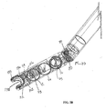
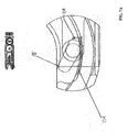
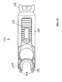
- the suturing device of the presently disclosed embodiments is shown generally at 50 in FIG. 1 .
- the suturing device 50 can be used to produce a continuous or interrupted stitch or suture so as to enable closure of openings internal to a patient's body.
- the suturing device 50 can be utilized to suture any type of anatomical tissue in any type of anatomical cavity; and, accordingly, while the device 50 is described hereinafter for use with a cannula in endoscopic procedures, such as laparoscopy, the device 50 can be used in open surgery and with catheters and other small and large diameter tubular or hollow, cylindrical members providing access to small cavities, such as veins and arteries, as well as large cavities, such as the abdomen.
- suturing device 50 includes an actuator mechanism shown generally at 52 which comprises an elongated barrel 54 and a handle 60 that extends from the undersides at a proximal end of the elongated barrel 54 .
- a suture head assembly 56 is attached to the distal end of the elongated barrel 54 .
- the suture head assembly 56 is removably attached to the distal end of the elongated barrel 54 .
- the length of the suture head assembly 56 can range from about 20 mm to about 100 nun. In an embodiment, the length of the suture head assembly 56 is about 50 mm.
- the length of the elongated barrel 54 can range from about 50 mm to about 400 mm.
- the elongated barrel 54 can be made shorter or longer depending on the intended use of the device 50 .
- the elongated barrel 54 is about 300 mm. In an embodiment, the elongated barrel 54 is about 350 mm.
- An articulation lever 66 just distal to the top of the handle 60 is pushed or pulled to cause the suture head assembly 56 to rotate. Moving the articulation lever 66 clockwise, moves the suture head assembly 56 to the right and moving the articulation lever 66 counterclockwise, moves the suture head assembly 56 to the left. The articulation lever 66 can also be moved to articulate the suture head assembly 56 up and down.
- the suture head assembly 56 is locked in place with a locking lever 64 located on an underside of the device 50 , below the articulation lever 66 .
- the suture head assembly 56 may be articulated, and the elongated barrel 54 may be any length appropriate for the intended clinical application of the device 50 .
- the diameter of the device 50 can range from about 3 mm to about 20 mm. In an embodiment, the diameter of the device 50 is about 12 mm. In an embodiment, the diameter of the device 50 is about 3 mm.
- a flush port 62 is located on the side of the elongated barrel 54 in order to provide a port of entry for cleaning fluids or suction such that the device 50 can be cleaned prior to or after use.
- the handle 60 is a grip that is squeezed in order to actuate the suturing device 50 .
- the suturing device 50 is actuated by the actuator mechanism 52 coupled to a drive mechanism 70 .
- the actuator mechanism 52 of the suturing device 50 may comprise a triggering mechanism that is known in the art, such as for example, the triggering mechanisms disclosed in U.S. Patent Nos. 6,053,908 and 5,344,061 .
- FIG. 2A is an exploded perspective view of the suture head assembly 56 with a cartridge holder assembly 90 located at the distal end to which a cartridge 88 can be attached.
- the suture head assembly 56 is fabricated as a single piece
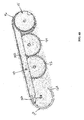
- FIG. 2B is a perspective assembly view of the suture head assembly of the presently disclosed embodiments showing part of the drive mechanism 70, shown as a gear train/pulley system including pulleys 72, 74, 76 and 78 .
- Located within the elongated barrel 54 are mechanical parts including drive shafts, belts, rods, cables, or hydraulic tubes which run from the elongated barrel 54 through the spherical portion 58 and then engages with the drive mechanism 70 in the suture head assembly 56.
- the drive mechanism 70 includes a gear train/pulley system ("locomotive-type" drive mechanism) and cables and rods that extend from the distal end of the suture head assembly 56 to the proximal end of the elongated barrel 54 .
- the suture head assembly 56 is that portion of the device 50 within which the mechanism for driving the curved needle 120 in a complete 360° circular arc, as well as the cartridge holder assembly 90 for attaching and releasing the cartridge 88 are situated.
- the suturing device 50 is unique in the fact that the orientation of the suture head assembly 56 is such that the when the cartridge 88 is attached to the suture head assembly 56 the needle 120 is driven in a curved path about an axis approximately perpendicular to the longitudinal axis of the device 50 . In this way, the needle 120 may be optimally visualized as the needle 120 is driven in a circular arc. Also, as shown in FIG. 2B , the needle 120 and cartridge 88 are in a plane parallel to the drive mechanism 70 and fit into the same space in the suture head assembly 56 .
- the improved visibility offered by the shape and configuration of the suture head assembly 56 enables precise device placement over the incision, and uniform advancement of the suturing device 50 after every stitch to provide a uniform and symmetric suture, thereby minimizing the risk of tearing tissue and bleeding due to a stitch being positioned too close to the edge of the incised tissue.
- the entire device 50 or parts of the device 50 such as the suture head assembly 56, the elongated barrel 54, the handle 60, and the needle 120 and cartridge 88, are composed of a sterilizable medical grade plastic material, in which case, the entire device 50 or parts of the device 50 may discarded and disposed after a single use.
- the device 50 is composed of a sterilizable medical grade metallic material such as stainless steel to enable reuse subsequent to sterilization following a prior use.
- the device 50 is composed of a sterilizable medical grade metallic material such as titanium to enable reuse subsequent to sterilization following a prior use.
- the use of titanium is ideal for certain procedures including Magnetic Resonance Imaging (MRI) and Computed Tomography (CT) because they are X-Ray radiolucent and do not interfere with MRI and CT scans.
- FIGS. 3A and 3B provide detailed segmental views of the suture head assembly 56 showing the cartridge holder assembly 90 , the disposable needle cartridge 88, a curved suturing needle 120, and parts of the drive mechanism 70 including a plurality of pulleys, 72, 74, 76, 78 and 80 involved in driving the needle driver 98 through a semicircular path.
- the needle driver is a pawl 98.
- a shoulder screw 108 is used to keep a latch 110 locked in place over the disposable cartridge 88 and the suturing needle 120 .
- Pulleys 72, 74, 76 and 78 are engaged with an actuator arm 102 , which is attached to the pawl 98.
- the pawl 98 interfits with two notches 132 located on the needle 120 at 180° apart which drives the curved needle 120 in a completely circular arc.
- the suture head assembly 56 is configured so that the pawl 98 or other needle driver known in the art, does not intrude into or obstruct the area within the curve of the needle 120 .
- the entire area within the circular arc of the needle 120 is unobstructed; there is no hub at the center of the circular arc so that the device 50 can encompass the maximum volume of tissue within the circular arc of the curved needle 120 . In this way, the needle 120 may be rotated through a relatively large arc, allowing the needle 120 to obtain a sufficient "bite" into the tissue.
- the needle 120 will have a radius of curvature of about 3 mm to about 40 mm.
- the device 50 sutures within the limit of the diameter of the suture head assembly 56 , which is advantageous to suturing through small cannulas during minimally invasive surgery.
- the diameter of the curved needle 120 does not exceed the diameter of the suture head assembly 56 .
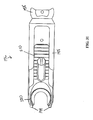
- FIGS. 4A and 4B show detailed views of the drive mechanism 70 located in the suture head assembly 56 with respect to driving the needle 120 during use of the device 50 (the cartridge housing 88 has been removed to show the drive mechanism 70 in detail).
- the drive mechanism 70 includes a plurality of pulleys, 72, 74, 76 and 78, and the associated axel pins 82, involved in driving the pawl 98 through a semicircular path.
- the actuator arm 102 engages pulleys 72 and 76 and are pinned 75 to pulleys 72 and 76.
- pulley 74 acts as an idler pulley, transferring the motion to the most distal pulley 72 .
- Pulley 72 and pulley 76 rotate through identical arcs.
- the actuator arm 102 provides a connection to the pawl 98.
- the pawl 98 is located in the distal end of the actuator arm 102 .
- the pawl 98 is attached to the actuator arm 102 by an integral shaft and collar 100 that fits loosely into the actuator arm 102 allowing smooth movement. As the handle 60 is closed and opened, the pawl 98 moves through the same arc as pulleys 72 and 76 .
- FIG. 4A shows a detailed view of the drive mechanism 70 and the suturing needle 120 either prior to using the device 50 or after one complete full cycle of the device 50 .
- FIG. 4B shows a detailed view of the drive mechanism 70 and the suturing needle 120 after one squeeze of the handle 60. As shown, the drive mechanism 70 has moved in a circular arc greater than about 180°, and about 190°, while the suturing needle 120 has moved in a circular arc of about 190° to drive through the tissue or vessel to be sutured.
- the outer surface of the actuator arm 102 is shaped to accommodate a C-brace (not shown) that causes the pawl 98 to engage the needle 120 and thereby remain in contact.
- the advancing movement of the needle 120 during operation causes the notches 132 along the radially inner edge of the needle 120 to align with the pawl 98 in the actuator arm 102, thereby causing the pawl 98 to engage the notches 132 due to a positive pressure exerted by the C-brace (not shown), and to "lock" into the notches 132.
- the rotary advancing movement of the needle 120 is therefore controlled to occur sequentially through about 190° each time the needle is actuated.
- FIG. 5A shows a close-up view of the distal end of the suture head assembly 56 with the cartridge 88 and the needle 120 in view as well as the relationship between the pawl 98 and the actuator arm 102 with respect to the needle 120.
- the needle 120 is enclosed within the cartridge 88 , so the sharp pointed end 124 is not exposed.
- This needle position, as loaded, is referred to as the "home" position ( FIG. 5A ).
- the needle 120 In the home position, the needle 120 is fully contained within the cartridge housing 88 to eliminate needle-pricks during handling of the cartridge 88 or the loaded device. Squeezing the device handle 60 fully, two times, operates the device 50 through one full cycle. As shown in FIG.
- the first full actuation of the handle 60 drives the needle 120 through an about 190° arc.
- the pointed end of the needle 124 exits the protective enclosure of the cartridge 88, drives through the tissue to be sutured, and re-enters the protection of the cartridge 88 of the device 50.
- This position after the first squeeze of the handle 60 , is referred to as the "rotation" position.
- the handle 60 is then released, and the needle 120 remains in the rotation position while the pawl 98 and the actuator arm 120 return to their start position.
- the handle 60 is then squeezed again driving the needle 120 through an about 190° arc and returning the needle 120 to the home position.
- FIG. 5A shows the needle 120 in the home position, the pawl 98 is engaged in the notch 132 near the suture end of needle 126.
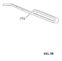
- An anti-rotate spring 136 is engaged in the notch 134 on the outer surface of the needle 120, not allowing the needle 120 to move backwards in the cartridge 88 of the device 50.
- a close-up view of the anti-rotate spring 136 is shown in FIG. 5B .
- the needle 120 comprises at least one anti-rotate notch 134 and is engaged with at least one anti-rotate spring 136.
- the anti-rotate spring 136 slips out of the notch 134 and slides over the outer surface of the needle 120.
- the anti-rotate spring 136 snaps in behind the rear corner of the needle 120 , near the suturing material or thread 146 (see FIG. 6A ). As the pawl 98 returns to the start position, the anti-rotate spring 136 holds the needle 120 in place, preventing the needle 120 from moving with the pawl 98 back toward the start position. The pawl 98 returns to the start position and engages the notch 132 in the needle 120 near the pointed end 124 (see FIG. 6B ). When the handle 60 is squeezed a second time, the needle 120 is driven back to the home position.
- the width of the aperture 118 in the cartridge 88 is comparable to and corresponds with the width of the gap in the needle 120 so that when the needle 120 is in the home position (as shown in FIG. 5A ) the needle 120 does not project materially into the aperture 118 .
- Such an alignment causes the needle 120 to reside entirely within the cartridge 88, thereby preventing inadvertent contact of the sharp pointed end 124 with the user's fingers during handling of the disposable needle cartridge 88 for placement on the cartridge holder assembly 90 or disposal after use, and while operating the suturing device 50 .
- Such protection of the needle 120 in the suturing device 50 prevents accidental "needle-pricks" from occurring, thereby substantially reducing the risk of infection caused by pathogenic bacteria or viruses that may contaminate the needle 120 during or after use prior to disposal.
- the needle 120 may be rotated in a curved track 92 of the cartridge 88 about the longitudinal axis of the suturing device 50 to advance the pointed needle end 124 so that the needle 120 first spans the aperture 118 and then returns to the home position.
- the suturing material or thread 146 is attached to the needle 120, and therefore follows the path of the needle 120 .
- the suturing material or thread 146 may then be cut and secured by an appropriate method, such as for example, by tying, or additional stitches may be placed along the entire wound or incision by repeating the aforementioned process. Every stitch, whether a single, interrupted stitch, or one of a series of continuous, running stitches may be placed in like manner.
- the suturing device 50 may be used to insert either a single stitch, or to insert a suture comprising a plurality of continuous stitches as a replacement method for a more tedious and time-consuming manual suturing process.
- the terminal end of the suturing material or thread 146 may contain a knot or button to prevent the suturing material or thread 146 from pulling through the sutured tissue during placement of the first stitch.
- the cartridge 88 comprises the suturing needle 120 attached to the terminal end suturing material or thread 146, and an appropriate length of suturing material or thread 146 are all packaged in a sterilizable medical packaging material.
- FIG. 7A shows a close-up view of the pawl 98 which rides in a track formed by the C-brace 106 and the suture head assembly 56 .
- the pawl 98 is spring loaded with a spring 104 .
- the spring 104 is engaged to the tip of the pawl 98b as shown in FIG. 7A .
- the spring 104 engages the pawl tip 98b into the notch 132 in the needle 120 during the driving stroke of the device 50 when the handle 60 is closed.
- the spring 104 also allows the tip of the pawl 98b to rotate out of notch 132 of the needle 120 during the return of the pawl 98 to the start position when the handle 60 is opened.
- FIG. 7B shows a close-up view of the pawl 98 showing the pawl heel 98a and the pawl tip 98b.
- the suture head assembly 56 is then positioned relative to the tissue/vessel to be sutured, and the user locks the suture head assembly 56 in place using the locking lever 64.
- the user then, through manipulation of suturing device 50, positions a plurality of separated tissue segments into the opening defined at the distal end portion of the suture head assembly 56 and within the aperture of the cartridge 118.
- the user using only one hand, may manipulate the device 50 while actuating the handle 60 to close an incision with a continuous suture whose stitches may be individually tensioned precisely and uniformly along the length of the suture similar to suturing done by hand in the conventional way.
- the user may employ a single suture which would extend the entire length of the incision or multiple sutures.
- the device 50 starts with the needle 120 in the home position and the handle 60 fully open (see FIG. 8 ).
- the handle 60 is made up of a grip which rests in the user's palm and is squeezed in order to actuate the device 50 .
- the user squeezes the handle 60 moving the needle 120 from the home position to the rotation position.
- the handle 60 contains linkages 144 to both the upper drive rod 142 and the lower drive rod 140. Squeezing the handle 60 (see FIG. 9 ) causes the two drive rods 140 and 142 to move in opposite directions.
- the upper drive rod 142 moves forward while the lower drive rod 140 moves backward.
- the drive rods are connected to the suture head assembly 56 with cables 84 and 86 and idler pulleys 80.
- the upper rod 142 is connected to pulley 78 with cable 84.
- the lower rod 140 is connected to pulley 76 with cable 86.
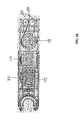
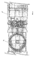
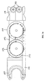
- FIGS. 10 and 11 in conjunction with FIG. 8 show the connections and positions of cables 84 and 86 and the drive pulleys 72, 74, 76 and 78 when the handle 60 is in the open position.
- FIGS. 12 and 13 in conjunction with FIG. 9 show the connections and positions of cables 84 and 86 and the drive pulleys 72, 74, 76 and 78 when the handle 60 is in the closed position.
- the force to move needle 120 from the home position to the rotation position comes from the lower rod 140 pulling backward on the drive cable 86.
- the lower rod 140 extends nearly the full length of the elongated barrel 54 , connecting to drive cable 86 , at the proximal end of the elongated barrel 54 . As shown in FIG.
- cable 86 exits the elongated barrel 54 and enters the suture head assembly 56 , passing over an idler pulley 80 located in the spherical portion 58 , then wrapping clockwise (as viewed from the bottom) around pulley 76 and is secured to pulley 76 located in the suture head assembly 56 .
- the pulling action of cable 86 causes pulley 76 to rotate through an arc of approximately 190°.
- the upper rod 142 moves forward.
- the upper rod 142 also extends nearly the full length of the elongated barrel 54 , connecting to drive cable 84 , at the proximal end of the elongated barrel 54. As shown in FIG.
- cable 84 also exits the elongated barrel 54 and enters suture head assembly 56 , passing over a second idler pulley 80 located in the spherical portion 58, then wrapping (clockwise as viewed from the top) around pulley 78 and is secured to pulley 78 located in the suture head assembly 56.
- Pulley 78 is directly linked to pulley 76 through the actuator arm 102 , and cables 84 and 86 are wrapped in opposing directions, so that as cable 86 unwinds from pulley 76 , cable 84 winds onto pulley 78 .
- the needle 120 is held in a path of rotation by a combination of three components.
- the cartridge 88 , the C-brace 106 and the cartridge holder assembly 90 interact to constrain the needle 120 to the path of rotation (see FIG. 5 ).
- the cartridge 88 is a semicircular shaped component that is held into the device 50 by a plurality of extensions 94 located on each end of the cartridge 88 (see FIGS. 14 and 15 ).
- the plurality of extensions 94 takes the form of tabs.
- the cartridge 88 is made from a sterilizable medical grade metallic material such as stainless steel.
- the cartridge 88 provides some of the support structure for keeping the needle 120 in a rotational path and therefore should be constructed from a material with structural integrity.
- the plurality of extensions are tabs extending from the cartridge housing 88 .
- the plurality of extensions 94 lock into mating grooves 96 located along on the distal edge of the cartridge holder assembly 90 that are located diametrically opposite to one another, and are capable of engaging the plurality of extensions 94 correspondingly located in the needle cartridge housing 88 as shown in FIG. 16 .
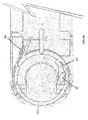
- the proximal end of cartridge 88 is held in place by a cartridge holder assembly 90, as shown in FIG. 17A .
- the cartridge holder assembly 90 also includes a latch 110 , a lever 112, associated pins 114 and 116 , a shoulder screw 108 , an anti-rotate spring 136 and at least one groove 96 that can engage with the plurality of extensions 94 located on the cartridge 88 . It is the interaction of all of the elements of the cartridge holder assembly 90 that hold and lock the cartridge 88 in place.
- the latch 110 slides back to release the cartridge 88 and forward to lock the cartridge 88 in place.
- the latch 110 also has a built into ejector feature, as shown in FIG . 17B .
- a lever 112 is located distal and below the needle 120 and the cartridge 88 .
- the lever 112 pivots on a pin 114 .
- a second pin 116 located above the pivot pin 114 , engages with a slot in the latch 110 .
- the latch 110 is pulled back and the lever 112 is rotated up and back, causing pin 116 to move back with the latch 110 and to rotate about pin 114 thus pushing the needle 120 and the cartridge 88 from the cartridge holder assembly 90 .
- the needle 120 and the cartridge 88 are then removed from the device 50 by a slight proximal motion to disengage the plurality of extensions 94 from their mating grooves 96 in the cartridge holder assembly 90 .
- 17C shows the needle 120 as it is driven through a first semi circular arc (the handle 60 has partially completed a first full squeeze).
- the anti-rotate spring 136 slips out of the notch 134 and slides over the outer surface of the needle 120 .
- Loading of the needle 120 and the cartridge 88 is accomplished by engaging the plurality of extensions 94 into both grooves 96 on the cartridge holder assembly 90 and then pressing the proximal ends down against the sloped distal surface of the latch 110 .
- the latch 110 is spring loaded at the proximal end, thus can slide back as the needle 120 and the cartridge 88 are pressed into place and then snap closed to the locked position, retaining the needle 120 and the cartridge 88 .
- the lever 112 is down and out of the way of the operation of the needle 120 and the cartridge 88 .
- FIG. 18 shows a close-up view of the needle 120 .
- the two notches 132 are located about 180° apart on the inner surface and assist in driving the needle 120 .
- the pawl 98 engages the notches 132 when driving the needle 120 through the circular motion.
- a third notch 134 is located on the outer surface of the needle 120 .
- the notch 134 assists in preventing rotation of the needle 120 and provides an anti-rotation feature.
- the needle 120 is formed as a circular split ring with a gap 122 , a sharp, pointed end 124 , and a blunt end 126 .
- the needle 120 further comprises an opening 130 to accommodate the leading end of the suturing material or thread 146 .
- the opening 130 is the form of an eye though which the leading end of the suturing material or thread 146 may be passed through for attachment to the needle 120.
- the opening 130 is located adjacent to the blunt end 126.
- the opening 130 can be positioned anywhere along the arc or the needle 120 between the apex 128 and the blunt end 126.
- the needle 120 comprises an opening 130 in the form of a cylindrical bore aligned axially with respect to the needle 120 , located at the blunt end 126 ( FIG. 19B ).
- the leading end of the suturing material or thread 146 is inserted into the opening 130 and restrained by mechanically crimping.
- the arc length of the needle 120 is preferably about 240° to about 300°.
- the needle 120 comprises two symmetric notches 132 along the radially inner edge ("inner notches") that are positioned proximally to the sharp, pointed end 124 and the blunt end 126 of the needle 120 .
- the notches 132 are located directly opposite to each other, each having a perpendicular (about 90°) segment and an angular segment that makes an angle of about 60° with the perpendicular segment.
- the inner notches 132 are engaged by the needle driver 98 of the drive mechanism 70 and enable the needle 120 to undergo a rotary movement upon actuation of the drive mechanism 70 , thereby causing the needle 120 to penetrate into and advance through tissue.
- a similar triangular notch 134 is located on the radially outer edge ("outer notch") of the needle 120 proximally to the inner notch 132 closer to the sharp, pointed end 124 .
- the outer notch 134 engages with the anti-rotate spring 136 located on the cartridge holder assembly 90 , whereby rotation of the needle 120 in a direction opposite to the advancing direction or "needle backing-up" is prevented.
- the positive engagement of the needle outer notch 134 during operation of the suturing device precludes needle 120 from straying out of sequence during the suturing process.
- the suture head assembly 56 of the device 50 can be laterally articulated to the left of center and also to the right of center. In an embodiment, the suture head assembly 56 can be laterally articulated through an arc of about 22.5° to the left of center and also to the right of center, for a total of about 45° or more. In addition, the suture head assembly can be articulated up and down. In an embodiment, the suture head assembly 56 can be articulated up and down. The ability of the suture head assembly 56 to be articulated to the left and right of center, as well as up and down, permits the user to position the suture head assembly 56 for many different types of suturing applications.
- the articulation lever 66 just distal of the top of the handle 60 is pushed or pulled to cause the suture head assembly 56 to rotate. Viewed from above, moving the articulation lever 66 clockwise, moves suture head assembly 56 to the right and moving the articulation lever 66 counterclockwise, moves suture head assembly 56 to the left.
- the suture head assembly 56 is locked in place with the locking lever 64 located on the bottom of the device 50 , below the articulation lever 66 . Movement is accomplished using the solid articulation rod 68 to link the articulation lever 66 to the suture head assembly 56 .
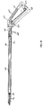
- the articulation rod 68 is pinned to the articulation lever 66 and to one side of the most proximal section of the suture head assembly 56 so that the articulation rod 68 pushes or pulls the suture head assembly 56 through a full range of motion (see FIGS. 20- 23 ).
- FIGS. 20-23 show the articulation rod 68 in the elongated barrel 54 and the connection to the suture head assembly 56 .
- the suture head assembly 56 is shown moving from left articulation, to straight to right articulation (some components are not shown to allow clear viewing of the linkage).
- FIG. 20 shows a side view of the suture head assembly 56.
- FIG. 21 shows a bottom view of the suture head assembly 56 with no articulation.
- FIG. 22 shows a bottom view of the suture head assembly 56 articulated to the left.
- FIG. 23 shows a bottom view of the suture head assembly 56 articulated to the right.
- FIGS. 20-23 show a number of items.
- the articulation rod 68 runs down the center of the elongated barrel 54 and is attached to one side of the spherical portion 58 .
- the function of the articulation rod 68 is to push and pull the suture head assembly 56 through an articulation.
- the two idler pulleys 80 which drive cables 84 and 86 are located in the spherical portion 58 . Looking at FIG. 20 , the two idler pulleys 80 seem to be one on top of the other, instead however, they are located in plane with either pulley 76 and lower rod 140 or pulley 78 and upper rod 142.
- the entire suturing device 50 can be designed as a single unit which may be either reusable or disposed after a single use. In an embodiment, the entire suturing device 50 can be designed from a number of units which, each unit may be either reusable or disposed after a single use.
- the suturing device 50 is configured to provide a "pistol like" grip for the user that includes an elongated barrel 54 and a handle 60 that extends from the proximal end of the elongated barrel 54 .
- the elongated barrel 54 has either a linear or non-linear configuration, including but not limited to, straight, curved and angled configurations.
- a suture head assembly 56 is removably attached to the distal end of the elongated barrel 54 .
- the suture head assembly 56 contains a portion of the drive mechanism 70 of the device 50 .
- the working end of the suture head assembly 56 has a cartridge holder assembly 90 to which a disposable cartridge 88 that is capable of accommodating a suturing needle 120 may reside.
- the disposable cartridge 88 has a generally cylindrical housing with an opening or aperture 118 in the sidewall of the housing at the distal or working end thereof.
- An arcuate suturing needle 120 having a sharp, pointed end 124 is slidably mounted in a circular track 92 of the cartridge 88 .
- a blunt end of the needle 126 is connected to a suturing material or thread 146 .
- the radius of the arc defining the arcuate suturing needle 120 is approximately equal to the circumference to the cartridge housing 88 at the aperture 118 therein.
- the needle 120 normally resides in a "home" position in the track 92 such that the gap in the arcuate suturing needle 122 is in alignment with the aperture 118 in the cartridge 88.
- the sharp, pointed end of the needle 124 is situated on one side and entirely within the confines of the housing aperture 118 ; the pointed end of the needle 124 is, therefore, shielded by the cartridge housing 88 .
- the blunt end of the suturing needle 126 that is attached to the suturing material or thread 146 is located at the opposite side of the aperture 118.
- the sharp, pointed end of the needle 124 is, therefore, wholly contained within the cartridge 88 and does not protrude beyond the housing of the cartridge 88. Thus, the sharp pointed end of the needle 124 is not exposed to the user.
- the needle 120 may be releasably engaged by a needle driver 98 that is rotatably mounted within the suture head assembly 56 so that the needle 120 can be rotated from the home position by about 360° about the central vertical axis of the cartridge 88.
- a rotary action of the needle 120 causes the sharp point 124 to advance across the cartridge housing 88 so as to span the aperture 118.
- the needle 120 penetrates the tissue segments and spans the incision between them.
- a continued rotary movement of the needle 120 causes the needle 120 to return to the home position, and thereby causes the suturing material or thread 146 attached to the needle 120 to be pulled into and through the tissue in an inward direction on one side of the tissue incision, and upwards and out through the tissue on the opposite side of the incision.
- the suture material or thread 146 follows the curved path of the needle 120 to bind the tissues together with a stitch of material or thread 146 across the incision in a manner similar to manual suturing, wherein the needle 120 is "pushed" from the blunt end 126 and then “pulled” from the pointed end 124 by the pawl 98 .
- an anchoring mechanism is provided at the trailing terminal end of the suturing material or thread 146 to prevent the material 146 from being pulled completely through and out of the tissue segments.
- the anchoring mechanism can be a pre-tied or a welded loop, a knot wherein the suture material or thread 146 is simply tied, or a double-stranded, looped suture is that attached to the suturing needle 120 .
- the rotary movement of the needle 120 within the needle cartridge 88 is accomplished by a pawl 98 that may be operated by the user by holding the suturing device 50 with one hand in a pistol-like grip around the handle 60 , and using at least one finger of that hand to activate.
- the suturing device 50 of the presently disclosed embodiments can be used for a laparoscopic procedure, including but not limited to laparoscopic colostomy, colectomy, adrenalectomy, splenectomy, repair of paraesophageal hernia, inguinal hernia repair, ventral hernia repair, Nissen fundoplication, liver lobectomy, gastrectomy, small bowel resection, treatment of small bowel obstruction, distal pancreatectomy, nephrectomy and gastric bypass.
- laparoscopic procedure including but not limited to laparoscopic colostomy, colectomy, adrenalectomy, splenectomy, repair of paraesophageal hernia, inguinal hernia repair, ventral hernia repair, Nissen fundoplication, liver lobectomy, gastrectomy, small bowel resection, treatment of small bowel obstruction, distal pancreatectomy, nephrectomy and gastric bypass.
- laparoscopic colostomy including but not limited
- the abdomen is insufflated with gas to create a working space for the user.
- gas Any gas known to those skilled in the art including, but not limited to, nitrogen or carbon dioxide, can be used.
- Access portals are established using trocars in locations to suit the particular surgical procedure. A variety of surgical instruments may then be inserted into the body through these access ports/cannulas. The user then introduces the distal end portion of suturing device 50 into a cannula, and then laterally articulates the suture head assembly 56 using the articulation lever 66 located just distal to the top of the handle 60 .
- the suture head assembly 56 is then positioned relative to the tissue/vessel to be sutured together, and the user locks the suture head assembly 56 in place using the locking lever 64 .
- the user then, through manipulation of suturing device 50 , positions a plurality of separated tissue segments into the opening defined at the distal end portion of the suture head assembly 56 and within the aperture 118 of the cartridge 88 .
- the user using only one hand, may manipulate the device 50 while actuating the handle 60 to close an incision with a continuous suture whose stitches may be individually tensioned precisely and uniformly along the length of the suture similar to suturing done by hand in the conventional way.
- the user may employ a single suture which would extend the entire length of the incision or multiple sutures.
- the suturing device 50 enables the user to lay down a running stitch or interrupted stitch to close the tissue incision in a time efficient manner.
- any conventional procedure for conducting laparoscopic surgery can be used with the device 50 .
- the needle cartridge 88 is disposably mounted on a cartridge holder assembly 90 at the distal end of the suture head assembly 56 .
- the minimalized structural design of the suture head assembly 56 enables the user to have a clear, unobstructed view of the suturing needle 120 during advancement through the tissue segments during the course of a suturing operation, thereby enabling precise placement of the suturing device 50 to provide uniform sutures and precluding the risk of tearing tissue by placement too close to the edge of the incision.
- the suturing device 50 is then advanced a short distance along the incision and the aforementioned operation is repeated to produce another stitch comprising the suturing material or thread 146 .
- the user may continue to manipulate the suturing device 50 , alternately advancing and actuating rotation of the needle 120 about an axis that is generally parallel to the direction of advancement to create a continuous suture which may extend through the entire length of the incision or a series of interrupted stitches.
- the stitch is tightened by exerting a pull on the suturing material or thread 146 so that the resultant suture is tensioned uniformly along the length of the incised tissue segments. Therefore, a tight closure of the segments is accomplished and bleeding and tearing of tissue are minimized.
- the user can use a needle grasper to tighten and knot the formed stitches.
- the presently disclosed embodiments provide a method for suturing tissue during minimally invasive surgery including engaging a cartridge 88 to a suture head assembly 56 at a distal end of a suturing device 50, the cartridge 88 having a protective housing and a suturing needle 120 with a pointed end 124 and a blunt end 126 ; introducing the distal end of the suturing device 50 into a body cavity; positioning an opening 118 in the cartridge 88 to span a plurality of separated tissue segments; activating an actuator 52 coupled to a drive mechanism 70 that engages the suturing needle 120 to cause rotational movement of the suturing needle 120 about an axis approximately perpendicular to a longitudinal axis of the suturing device 50 and advance the suturing needle 120 through the plurality of separated tissue segments; and pulling a suturing material 146 attached to the suturing needle 120 through the plurality of separated tissue segments forming a stitch.
- a method for suturing tissue during minimally invasive surgery including (a) engaging a cartridge 88 to a suture head assembly 56 at a distal end of a suturing device 50 , the cartridge 88 having a protective housing and a suturing needle 120 with a pointed end 124 and a blunt end 126 ; (b) introducing the distal end of the suturing device 50 into a body cavity; (c) positioning an opening 118 in the cartridge 88 to span a plurality of separated tissue segments; (d) activating an actuator 52 coupled to a drive mechanism 70 that engages the suturing needle 120 to cause rotational movement of the suturing needle 120 about an axis approximately perpendicular to a longitudinal axis of the suturing device 50 and advance the suturing needle 120 through the plurality of separated tissue segments; (e) pulling a suturing material 146 attached to the suturing needle 120 through the plurality of separated tissue segments forming a stitch and repeating steps (c) through (e) to cause a plurality of
- a method for suturing tissue during minimally invasive surgery including inserting a distal end of a suturing device 50 having a suturing needle 120 with a pointed end 124 into a body; positioning the suturing needle 120 to span a plurality of separated tissue segments; activating an actuator 52 a first time causing the pointed end 124 of the suturing needle 120 to extend beyond a protective housing of a cartridge 88 to engage the plurality of separated tissue segments; activating the actuator 52 a second time to cause the suturing needle 120 to complete a revolution and pull a suture 146 extending from the suturing needle 120 through the plurality of separated tissue segments to form a stitch.
- the suturing device 50 may be configured in different ways with respect to length and angle of the suture head assembly 56 .
- the size of the needle 120 , the needle cartridge 88 , the cartridge aperture 118 and the aperture position may also be varied for use in open surgery to perform procedures such as closing of the fascia, skin closure, soft tissue attachment, anastomosis, fixation of mesh, grafts and other artificial materials.
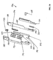
- FIGS. 24 and 25 show an alternative embodiment of a suturing device shown generally at 150 .
- the suturing device 150 can be used to produce a continuous or interrupted stitch or suture so as to enable closure of openings internal to a patient's body.
- the suturing device 150 can be utilized to suture any type of anatomical tissue in any type of anatomical cavity; and, accordingly, while the device 150 is described hereinafter for use with a cannula in endoscopic procedures, such as laparoscopy, the device 150 can be used in open surgery and with catheters and other small and large diameter tubular or hollow, cylindrical members providing access to small cavities, such as veins and arteries, as well as large cavities, such as the abdomen.
- the suturing device 150 includes an actuator mechanism shown generally at 152 which comprises an elongated barrel 154 and a handle 160 that extends from the undersides at a proximal end of the elongated barrel 154 .
- Located within the elongated barrel 154 are mechanical parts including cables which run from the elongated barrel 154 through a spherical portion 158 and then engages with the drive mechanism in a suture head assembly 156 .
- the spherical portion 158 resides within the distal portion of the elongated barrel 154 and rotates with low friction.
- a drive mechanism 170 includes a pulley system and cables that extend from the distal end of the suture head assembly 156 to the proximal end of the elongated barrel 154 .
- the suture head assembly 156 houses the mechanism for driving a curved needle 220 in a complete 360° circular arc.
- the orientation of the suture head assembly 156 is such that when the needle 220 is attached to the suture head assembly 156 the needle 220 is driven in a curved path about an axis approximately perpendicular to the longitudinal axis of the device 150 . In this way, the needle 220 may be optimally visualized as the needle 220 is driven in a circular arc. Also, as shown in FIGS. 24 and 25 , the needle 220 is in a plane parallel to the drive mechanism and fits into the same space in the suture head assembly 156 .
- the improved visibility offered by the shape and configuration of the suture head assembly 156 enables precise device placement over the incision, and uniform advancement of the suturing device 150 after every stitch to provide a uniform and symmetric suture, thereby minimizing the risk of tearing tissue and bleeding due to a stitch being positioned too close to the edge of the incised tissue.
- the entire device 150 or parts of the device 150 such as the suture head assembly 156 , the elongated barrel 154 , the handle 160 , and the needle 220 , are composed of a sterilizable medical grade plastic material, in which case, the entire device 150 or parts of the device 150 may discarded and disposed after a single use.
- the device 150 is composed of a sterilizable medical grade metallic material such as stainless steel to enable reuse subsequent to sterilization following a prior use.
- the device 150 is composed of a sterilizable medical grade metallic material such as titanium to enable reuse subsequent to sterilization following a prior use.
- the use of titanium is beneficial for certain procedures including Magnetic Resonance Imaging (MRI) and Computed Tomography (CT) because they are X-Ray radiolucent and do not interfere with MRI and CT scans.
- FIG. 24 shows the handle 160 in an open position.
- FIG. 25 shows the handle 160 in the closed position.
- the suture head assembly 156 is attached to the distal end of the elongated barrel 154 .
- the suture head assembly 156 is removably attached to the distal end of the elongated barrel 154.
- the length of the suture head assembly 156 can range from about 10 mm to about 100 mm. In an embodiment, the length of the suture head assembly 156 is about 40 mm.
- the length of the elongated barrel 154 can range from about 50 mm to about 400 mm. Those skilled in the art will recognize that the elongated barrel 154 can be made shorter or longer depending on the intended use of the device 150.
- the elongated barrel 154 is about 300 mm. In an embodiment, the elongated barrel 154 is about 350 mm.
- An articulation lever 166 just distal to the top of the handle 160 is pushed or pulled to cause the suture head assembly 156 to rotate. Moving the articulation lever 166 clockwise, moves the suture head assembly 156 to the right and moving the articulation lever 166 counterclockwise, moves the suture head assembly 156 to the left. The articulation lever 166 can also be moved to articulate the suture head assembly 156 up and down. The suture head assembly 156 is locked in place with a locking lever 164 located on an underside of the device 150, below the articulation lever 166.
- the suture head assembly 156 may be articulated, and the elongated barrel 154 may be any length appropriate for the intended clinical application of the device 150.
- the diameter of the device 150 can range from about 3 mm to about 20 mm. In an embodiment, the diameter of the device 150 is about 12 mm. In an embodiment, the diameter of the device 150 is about 3 mm.
- the handle 160 may be a grip that is squeezed in order to actuate the suturing device 150.
- the suturing device 150 is actuated by the actuator mechanism 152 coupled to a drive mechanism 170.
- the actuator mechanism 152 of the suturing device 150 may comprise a triggering mechanism that is known in the art, such as for example, the triggering mechanisms disclosed in U.S. Patent No. 6,053,908 and U.S. Patent No. 5,344,061 .
- the actuator mechanism 152 can be either a manually operable button or switch, or mechanically operable by an automated electrical or a fuel driven device, such as for example, an electrical, electromagnetic or pneumatic motor powered by electrical, electromagnetic, compressed air, compressed gas, hydraulic, vacuum or hydrocarbon fuels.
- an electrical, electromagnetic or pneumatic motor powered by electrical, electromagnetic, compressed air, compressed gas, hydraulic, vacuum or hydrocarbon fuels such as for example, an electrical, electromagnetic or pneumatic motor powered by electrical, electromagnetic, compressed air, compressed gas, hydraulic, vacuum or hydrocarbon fuels.
- FIG. 26 provides an assembly view of the suture head assembly 156.
- the suture head assembly 156 is fabricated from multiple pieces including a holder assembly 190, a needle holder assembly 188, a latch 210, and parts of the drive mechanism 170 including a plurality of pulleys, 172, 174 and 176 and two idler pulleys 180 involved in driving a needle driver 198 through a semicircular path.
- Pulleys 172 and 174 consist of a set of four pulleys, or two sets of pulleys, labeled 178.
- the needle driver is a pawl 198.
- a shoulder screw 208 and a plurality of needle assembly extensions 194 are used to keep the latch 210 locked in place over the needle holder assembly 188 and the suturing needle 220.
- the needle holder assembly 188 includes a curved track 192 where the needle 220 rides. Pulleys 172 , 174 and 176 are engaged with an actuator arm 202 , which is attached to the pawl 198 .
- the pawl 198 interfits with two notches 232 located on the face of the needle 220 at about 180° apart which drives the curved needle 220 in a circular arc.
- the suture head assembly 156 is configured so that the pawl 198 or other needle driver known in the art, does not intrude into or obstruct the area within the curve of the needle 220 .
- the area within the circular arc of the needle 220 is unobstructed; there is not a hub at the center of the circular arc so that the device 150 can encompass the maximum volume of tissue within the circular arc of the curved needle 220 .
- the needle 220 may be rotated through a relatively large arc, allowing the needle 220 to obtain a sufficient "bite" into the tissue.
- the needle 220 will have a radius of curvature of about 3 mm to about 40 mm.
- the device 150 sutures within the limit of the diameter of the suture head assembly 156, which is advantageous to suturing through small cannulas during minimally invasive surgery.
- the diameter of the curved needle 220 does not exceed the diameter of the suture head assembly 156.
- FIGS. 27A and 27B show detailed views of the drive mechanism 170 located in the suture head assembly 156 with respect to driving the needle 220 during use of the device 150 (the needle holder assembly 188 and the holder assembly 190 have been removed to show the drive mechanism 170 in detail).
- the drive mechanism 170 includes the actuator arm 202 that engages pulleys 172, 174, and 176 and the pawl 198 that drives the needle 220 through a curved path.
- the pawl 198 is located in the distal end of the actuator arm 202 and is capable of engaging the notches 232 located along the face of the needle 220 .
- a flat spring 200 keeps the pawl 198 engaged into the notches 232 of the needle 220.
- the pawl 198 When the needle 220 is pushed around, the pawl 198 will be pushed back up against the flat spring 200 and allow the needle 220 to cycle. As the handle 160 is closed and opened, the pawl 198 moves through the same arc as the pulleys.
- the actuator arm 202 is activated by the user upon squeezing of the handle 160, and is capable of sweeping back and forth in an arc spanning about 190° or more.
- FIG. 28 shows a close-up view of the needle holder assembly 188 showing the curved track 192 where the needle 220 resides as well as the needle holder assembly extensions 194 that help keep the latch 210 in place.
- the suturing needle 220 follows a curved path along the track 192 during rotation of the suturing needle 220 .
- the curved track 192 for the needle 220 may be machined into the needle assembly 188 and provides a captive curved track 192 so that the needle 220 can be driven around with precision.
- the curved track 192 includes an inside slot and a larger slot surrounding the inside slot.
- the larger outside slot provides clearance for the pawl 198 , so that the pawl 198 can maneuver around without hitting anything
- the smaller inside slot provides clearance for a pawl tip 199 , which goes through the smaller inside slot and then into the needle 220 so that the pawl tip 199 can drive the needle 220.
- FIG. 29 shows a close-up view of the suture head assembly 156 with the needle holder assembly 188 , the holder assembly 190 , the latch 210 and the needle 220 in view as well as the relationship between the pawl 198 and the actuator arm 202 with respect to the needle 220 .
- the needle 220 is enclosed within the needle holder assembly 188 , so the sharp pointed end 224 of the needle 220 is not exposed.
- This needle 220 position, as loaded, is referred to as the "home" position. In the home position, the needle 220 is fully contained within the needle holder assembly 188 to eliminate needle-pricks during handling of the suture head assembly 156 .
- the needle assembly extensions 194 form a "tongue-in-groove" connection with the latch 210 , which keeps the forces from the needle 220 from opening the thin members of the latch 210 .
- the needle assembly extensions 194 cause an entrapment at a distal end of the suturing device, thus locking the latch 210 in place.
- Squeezing the device handle 160 fully operates the device 150 through one full cycle.
- the first full actuation of the handle 160 drives the needle 220 through an about 190° arc.
- the pointed end 224 of the needle 220 exits the protective enclosure of the needle holder assembly 188 , drives through the tissue to be sutured, and re-enters the protection of the needle holder assembly 188 of the device 150 .
- This position after the first squeeze of the handle 160 , is referred to as the "rotation" position.
- the handle 160 is then released, and the needle 220 remains in the rotation position while the pawl 198 and the actuator arm 220 return to their start position.
- the handle 160 is then squeezed again driving the needle 220 through an about 190° arc and returning the needle 220 to the home position.
- a flat pawl spring 200 keeps the pawl 198 engaged into the pawl notches 232 on the needle 220 .
- the needle 220 is pushed around the pawl 198 will be pushed back up against the flat pawl spring 200 and allow the needle 220 to cycle.
- FIGS. 30 and 31 show top views of the suture head assembly 156.
- Needle holder assembly 188 forms a connection with the latch 210.
- the latch 210 forms a top cover over the suturing needle 220 which is in the curved track 192 of the needle holder assembly 188.
- FIG. 30 shows the latch 210 in the open position, which is for needle 220 removal and insertion into the needle holder assembly 188.
- a user may turn the needle 220 180° in its curved track 192 from the as-drawn position.
- a user may grab the needle 220 by hand or with a surgical tool to either install the needle 220 or remove the needle 220 . By grabbing the needle 220, lifting the needle 220 out, the needle 220 is removed. By grabbing the needle 220 the needle can be inserted when the latch 210 in the open position.
- FIG. 31 shows the latch 210 in the locked position, also known as the forward position.
- FIG. 32 shows the suturing needle 220.
- the two notches 232 are located about 180° apart on the face of the needle 220 and assist in driving the needle 220 .
- the pawl 198 engages the notches 232 when driving the needle 220 through the circular motion.
- a third notch 234 is located on the outer surface of the needle 220.
- the notch 234 provides an anti-rotation feature by preventing rotation of the needle 220.
- the needle 220 is formed as a circular split ring with a gap 222 , a sharp, pointed end 224, and a blunt end 226.
- the needle 220 further comprises an opening 230 to accommodate the leading end of the suturing material or thread 246.
- the opening 230 is the form of an eye though which the leading end of the suturing material or thread 246 may be passed through for attachment to the needle 220.
- the needle 220 comprises an opening 230 in the form of a cylindrical bore aligned axially with respect to the needle 220, located at the blunt end 226.
- the opening 230 can be positioned anywhere along the arc or the needle 220 between the apex 228 and the blunt end 226 .
- the leading end of the suturing material or thread 246 is inserted into the opening 230 and restrained by mechanically crimping or other connection methods known in the art.
- the arc length of the needle 220 is preferably about 240° to about 300°.
- the needle 220 comprises two symmetric notches 232 along the face ("drive notches”). The notches 232 are located directly opposite to each other.
- a similar notch 234 is located on the radially outer edge ("outer notch") of the needle 220 proximally to the inner notch 232 closer to the sharp, pointed end 224 .
- the outer notch 234 engages with an anti-rotate spring, whereby rotation of the needle 220 in a direction opposite to the advancing direction or "needle backing-up" is prevented.
- the positive engagement of the needle outer notch 234 during operation of the suturing device precludes the needle 220 from straying out of sequence during the suturing process.
- FIG. 33 shows a close-up view of the pawl tip 199 engaging the drive notches 232 of the needle 220 .
- the drive notches 232 are engaged by the pawl tip 199 of the drive mechanism 170 and enable the needle 220 to undergo a rotary movement upon actuation of the drive mechanism 170 , thereby causing the needle 220 to penetrate into and advance through tissue.
- FIGS. 34 and 35 show parts of the drive mechanism 170 including return pulleys 172 and 174.
- Pulleys 172 and 174 are connected to each other using wires 175 .
- pulleys 172 and 174 are made up of four pulleys 178 that are connected together by laser welding or other methods known in the art.
- the four pulleys 178 produce an over-rotation, about a 190°-rotation.
- the over-rotation leads to the wire 175 design where there is a wire 175 on each set of pulleys 178.
- FIG. 35 shows a side view of the suture head assembly 156 which shows the two wires 175 connecting the four pulleys 178 together for synchronized rotation.
- FIGS. 36 and 37 in conjunction with FIG. 38 show the connections and positions of cables 184 and 186 to the drive pulley 176 and to the return pulleys 172 and 174 , respectively, and to the when the handle 160 is in the open position.
- the cables 184 and 186 may be made from stainless steel.
- FIG. 36 shows a top view of the suture head assembly 156 with the cable 184 running through two idler pulleys 180 and wrapped around drive pulley 176.
- FIG. 37 shows a top view of the suture head assembly 156 with the cable 186 running through two idler pulleys 180 and wrapped around return pulley 174.
- the cable 186 runs from return pulley 174 through the elongated barrel 154 and to the very proximal end of the handle 160.
- the force to move the needle 220 from the home position (shown in FIGS. 36 and 37 ) to a rotation position comes from a return spring 240 that is connected to the cable 184 , resulting in a pre-load (shown in FIG. 38 ).
- the trigger of the handle 160 is squeezed closed, the handle 160 moves to the closed position and the drive pulley 176 turns counterclockwise, driving the needle 220.
- the cable 186 drives the return pulley 174 counterclockwise and cycles the actuator arm 202 to drive the needle 220 forward through the tissue.
- the needle 220 is driven through a circular motion, through a cycle, and the cable 184 is compressing the return spring 240 on the other end.
- the actuator arm 202 drives the needle.
- the front pulley 178 which is now fully charged with the return spring 240, will return the needle 220 to the home position. Relaxing the trigger of handle 160 takes no power.
- FIG. 38 shows a side elevational view of the suturing device 150.
- the handle 160 includes a number of internal parts.
- a cable connector 182 has a hole and a shoulder. The shoulder rides against the end of the return spring 240 , and the hole provides an opening for the cable 184.
- the return spring 240 is compressed and the cable 184 is soldered or locked to the connector 182 , so that the cable 184 provides a preload onto the return spring 240 .
- the cable 184 runs from the connector 182 through the return spring 240 over pulley 244 , through the elongated barrel 154 , through the spherical portion 158 , between the idler pulleys 180 and fixed to the drive pulley 176 .
- the cable 186 is connected at the very proximal end of the handle 160 and lies under pulley 245 , over pulley 242 , through the elongated barrel 154 , through the spherical portion 158 , between the idler pulleys 180 and fixed to the return pulley 174.
- the handle 160 When the handle 160 is translated from the open position to the closed position the needle 220 is driven through the tissue. A user has a tactile feel as the needle 220 moves. If the needle 220 runs across something that is impenetrable, the handle 160 will stop moving and the user could feel this in their hand holding the handle.
- the return spring 240 takes on a charge, the return spring 240 has shortened in length.
- the return spring 240 pulls the cable 184 and brings the needle 220 back to the home position and also brings the handle 160 back to the open position.
- the return spring 240 provides a load on the cable 184.
- a loop is formed throughout the suturing device 150 that includes the cables 184 and 186 and the pulleys 172, 174 and 176 such that cable 184 is attached at one end to the return spring 240, at the other end to the drive pulley 176.
- the cable 186 is attached to the return pulley 174 and then cable 186 attaches to the very proximal end of the handle 160, thus forming a loop.
- the return spring 240 can be set to a desired spring-rate so that the return spring 240 performs as desired by the user.
- the return spring 240 should have a small amount of preload to make sure that the handle 160 opens all the way, which provides that the driving mechanism 170 would return the needle 220 to the home position.
- the cables 184 and 186 extend through the elongated barrel 154 and connect to the drive mechanism 170 in the suture head assembly 156.
- the long length of the cables 184 and 186 provides a small amount of a spring buffer. If the suturing device 150 were to become bound or something locked up at the suture head assembly 156 this would not translate. If the user continued to pull on the handle 160 to close the handle 160, the cables 184 and 186 would stretch and should not break.
- the two idler pulleys 180, which drive the cables 184 and 186 are located in the spherical portion 158. As shown in FIG. 39, the two idler pulleys 180 appear to be one on top of the other, but they are located in a plane with either pulleys 174 and 176 or pulley 178.
- the entire suturing device 150 can be designed as a single unit which may be either reusable or disposed after a single use. In an embodiment, the entire suturing device 150 can be designed from a number of separable parts where each unit may be either reusable or disposed after a single use.
- the suturing device 150 is configured to provide a "pistol like" grip for the user that includes an elongated barrel 154 and a handle 160 that extends from the proximal end of the elongated barrel 154.
- the elongated barrel 154 has either a linear or non-linear configuration, including but not limited to, straight, curved and angled configurations.
- a suture head assembly 156 is removably attached to the distal end of the elongated barrel 154.
- the suture head assembly 156 contains a portion of the drive mechanism 170 of the device 150.
- the working end of the suture head assembly 156 has a needle holder assembly 188 to which a suturing needle 220 may reside.
- a latch 210 forms a cover over the needle 220.
- An arcuate suturing needle 220 having a sharp, pointed end 224 is slidably mounted in a circular track 192 of the needle holder assembly 188.
- the blunt end of the needle 226 is connected to the suturing material or thread 246.
- the needle 220 normally resides in a "home" position in the track 192 such that the gap in the arcuate suturing needle 222 is in alignment with an aperture 218 in the needle holder assembly 188.
- the sharp, pointed end of the needle 224 is situated on one side and entirely within the confines of the needle holder aperture 218 ; the pointed end of the needle 224 is, therefore, shielded by the needle holder assembly 188.
- the blunt end of the suturing needle 226 that is attached to the suturing material or thread 246 is located at the opposite side of the aperture 218.
- the sharp, pointed end of the needle 224 is, therefore, wholly contained within the needle holder assembly 188 and does not protrude beyond the housing of the needle holder assembly 188. Thus, the sharp pointed end of the needle 224 is not exposed to the user.
- the needle 220 may be releasably engaged by the needle driver 198 that is rotatably mounted within the suture head assembly 156 so that the needle 220 can be rotated from the home position by about 360° about the central vertical axis of the needle holder assembly 188.
- Such a rotary action of the needle 220 causes the sharp point 224 to advance across the needle holder assembly 188 so as to span the aperture 218 .
- the needle 220 penetrates the tissue segments and spans the incision between them.
- a continued rotary movement of the needle 220 causes the needle 220 to return to the home position, and thereby causes the suturing material or thread 246 attached to the needle 220 to be pulled into and through the tissue in an inward direction on one side of the tissue incision, and upwards and out through the tissue on the opposite side of the incision.
- the suture material or thread 246 follows the curved path of the needle 220 to bind the tissues together with a stitch of material or thread 246 across the incision in a manner similar to manual suturing, wherein the needle 220 is "pushed" from the blunt end 226 and then “pulled” from the pointed end 224 by the pawl 198 .
- an anchoring mechanism is provided at the trailing terminal end of the suturing material or thread 246 to prevent the material 246 from being pulled completely through and out of the tissue segments.
- the anchoring mechanism can be a pre-tied or a welded loop, a knot wherein the suture material or thread 246 is simply tied, or a double-stranded, looped suture is that attached to the suturing needle 220 .
- the rotary movement of the needle 220 within the needle holder assembly 188 is accomplished by a pawl 198 that may be operated by the user by holding the suturing device 150 with one hand in a pistol-like grip around the handle 160, and using at least one finger of that hand to activate.
- the suturing device 150 of the presently disclosed embodiments can be used for a laparoscopic procedure, including but not limited to laparoscopic colostomy, colectomy, adrenalectomy, splenectomy, repair of paraesophageal hernia, inguinal hernia repair, ventral hernia repair, Nissen fundoplication, liver lobectomy, gastrectomy, small bowel resection, treatment of small bowel obstruction, distal pancreatectomy, nephrectomy and gastric bypass.
- laparoscopic procedure including but not limited to laparoscopic colostomy, colectomy, adrenalectomy, splenectomy, repair of paraesophageal hernia, inguinal hernia repair, ventral hernia repair, Nissen fundoplication, liver lobectomy, gastrectomy, small bowel resection, treatment of small bowel obstruction, distal pancreatectomy, nephrectomy and gastric bypass.
- laparoscopic colostomy including but not limited
- the abdomen is insufflated with gas to create a working space for the user.
- gas Any gas known to those skilled in the art including, but not limited to, nitrogen or carbon dioxide, can be used.
- Access portals are established using trocars in locations to suit the particular surgical procedure. A variety of surgical instruments may then be inserted into the body through these access ports/cannulas. The user then introduces the distal end portion of suturing device 150 into a cannula, and then laterally articulates the suture head assembly 156 using the articulation lever 166 located just distal to the top of the handle 160.
- the suture head assembly 156 is then positioned relative to the tissue/vessel to be sutured together, and the user locks the suture head assembly 156 in place using the locking lever 164.
- the user then, through manipulation of the suturing device 150 , positions a plurality of separated tissue segments into the opening defined at the distal end portion of the suture head assembly 156 and within the aperture 218 of the needle holder assembly 188 .
- the user using only one hand, may manipulate the device 150 while actuating the handle 160 to close an incision with a continuous suture whose stitches may be individually tensioned precisely and uniformly along the length of the suture similar to suturing done by hand in the conventional way.
- the user may employ a single suture which would extend the entire length of the incision or multiple sutures.
- the suturing device 150 enables the user to lay down a running stitch or interrupted stitch to close the tissue incision in a time efficient manner.
- any conventional procedure for conducting laparoscopic surgery can be used with the device 150.
- the minimalized structural design of the suture head assembly 156 enables the user to have a clear, unobstructed view of the suturing needle 220 during advancement through the tissue segments during the course of a suturing operation, thereby enabling precise placement of the suturing device 150 to provide uniform sutures and precluding the risk of tearing tissue by placement too close to the edge of the incision.
- the suturing device 150 is then advanced a short distance along the incision and the aforementioned operation is repeated to produce another stitch comprising the suturing material or thread 246.
- the user may continue to manipulate the suturing device 150, alternately advancing and actuating rotation of the needle 220 about an axis that is generally parallel to the direction of advancement to create a continuous suture which may extend through the entire length of the incision or a series of interrupted stitches.
- the stitch is tightened by exerting a pull on the suturing material or thread 246 so that the resultant suture is tensioned uniformly along the length of the incised tissue segments. Therefore, a tight closure of the segments is accomplished and bleeding and tearing of tissue are minimized.
- the user can use a needle grasper to tighten and knot the formed stitches.
- the suturing device 150 may be configured in different ways with respect to length and angle of the suture head assembly 156 .
- the size of the needle 220 , the needle holder assembly 188, the needle holder aperture 218 and the aperture position may also be varied for use in open surgery to perform procedures such as closing of the fascia, skin closure, soft tissue attachment, anastomosis, fixation of mesh, grafts and other artificial materials.
Claims (14)
- Dispositif de suture (50) pour effectuer des points de suture de manière imperceptiblement invasive, comprenant :un barillet allongé (54) ayant une extrémité proximale, une extrémité distale et un axe longitudinal entre ces dernières ;un ensemble formant tête de suture (56) s'étendant à partir de l'extrémité distale du barillet allongé (54) ayant une ouverture (118) et une piste d'aiguille circulaire (192) pour recevoir une aiguille de suture (120) ;ladite aiguille de suture (120) ayant une extrémité pointue (124) et un corps incurvé susceptible de tourner autour d'un axe perpendiculaire à un axe longitudinal du barillet allongé (54), dans lequel l'extrémité pointue (124) de l'aiguille de suture (120) est positionnée à l'intérieur de l'ensemble formant tête de suture (56) avant et après une rotation complète de l'aiguille de suture (120) ; et une zone incluant au moins le centre de la piste circulaire à l'intérieur de l'arc circulaire de l'aiguille est non obstruée de sorte que l'ensemble formant tête de suture (56) peut englober une quantité maximale de tissu à l'intérieur de l'arc circulaire de l'aiguille de suture (120) ;un actionneur s'étendant à partir de l'extrémité proximale du barillet allongé (54) pour actionner un mécanisme d'entraînement ayant un dispositif d'entraînement d'aiguille pour mettre en prise et faire tourner l'aiguille de suture (120)caractérisé en ce quel'aiguille de suture (120) a une extrémité émoussée (126) et en ce quel'aiguille de suture (120) est munie d'une première et d'une seconde encoche (132) et en ce quele dispositif d'entraînement d'aiguille comprend un cliquet (98) et le mécanisme d'entraînement comprend un bras d'actionneur (102) auquel le cliquet (98) est relié, et une poulie ou un train d'engrenages (72, 74, 76, 78, 172, 174) qui supporte le bras d'actionneur (102) et le cliquet (98) de sorte que le cliquet (98) est susceptible de :(a) mettre en prise l'encoche (132) au début d'une première course d'entraînement dans une position de départ ;(b) déplacer l'aiguille le long de la piste d'aiguille jusqu'à une position de rotation dans laquelle l'aiguille enjambe l'ouverture dans la tête de suture ; et(c) se dégager de l'aiguille et revenir à la position de départ, dans laquelle le mécanisme d'entraînement est conçu pour
avancer l'aiguille par une rotation de 360° dans une pluralité de courses d'entraînement, et dans lequel le mécanisme d'entraînement est conçu pour mettre en prise la seconde encoche (132) de l'aiguille pendant une seconde course d'entraînement. - Dispositif de suture (50) selon la revendication 1, dans lequel le mécanisme d'entraînement est conçu et configuré pour déplacer le cliquet (98) au moins en partie le long d'un chemin incurvé proche de l'aiguille.
- Dispositif de suture (50) selon la revendication 1 ou la revendication 2, dans lequel l'aiguille a une longueur d'arc entre autour de 240° et environ 300°.
- Dispositif de suture (50) selon n'importe laquelle des revendications précédentes, dans lequel l'au moins une encoche (132) pour entraîner l'aiguille (120) est définie au moins en partie par un segment perpendiculaire qui est conçu et configuré pour recevoir le cliquet (98).
- Dispositif de suture (50) selon la revendication 4, dans lequel l'au moins une encoche (132) inclut en outre un segment angulaire qui forme un angle d'environ 60° par rapport au segment perpendiculaire.
- Dispositif de suture (50) selon n'importe laquelle des revendications précédentes, dans lequel le mécanisme d'entraînement est en outre conçu pour :a) mettre en prise une seconde encoche d'entraînement (132) dans l'aiguille (120) au début d'un second cycle ;b) déplacer l'aiguille (120) autour de la piste d'aiguille jusqu'à la position de repos d'aiguille ; etc) se dégager de l'aiguille (120) et revenir à la position de repos du mécanisme d'entraînement.
- Dispositif de suture (50) selon la revendication 6, dans lequel l'aiguille est avancée par une rotation de 360° après que le mécanisme d'entraînement revient à sa position de repos après le second cycle.
- Dispositif de suture (50) selon n'importe laquelle des revendications précédentes comprenant en outre :a) une tige d'articulation susceptible d'articuler latéralement l'ensemble formant tête de suture (56) ; etb) un levier de verrouillage pour verrouiller l'ensemble formant tête de suture (56) en position.
- Dispositif de suture (50) selon n'importe laquelle des revendications précédentes, dans lequel l'aiguille (120) repose dans un plan qui est parallèle au mécanisme d'entraînement.
- Dispositif de suture (50) selon n'importe laquelle des revendications précédentes, dans lequel le mécanisme d'entraînement dans l'ensemble formant tête de suture (56) ne s'immisce pas dans la zone à l'intérieur de la courbe de l'aiguille.
- Dispositif de suture (50) selon n'importe laquelle des revendications précédentes, dans lequel l'ensemble formant tête de suture (56) inclut en outre un verrou pour couvrir de manière sélective l'aiguille (120) et conserver l'aiguille (120) à l'intérieur de l'ensemble formant tête de suture (56).
- Dispositif de suture (50) selon n'importe laquelle des revendications précédentes, dans lequel l'ensemble formant tête de suture (56) est conçu et configuré pour être introduit à travers une canule.
- Dispositif de suture (50) selon la revendication 12, dans lequel l'ensemble formant tête de suture (56) a une largeur maximale entre environ 3 mm et environ 20 mm.
- Dispositif de suture (50) selon n'importe laquelle des revendications précédentes, comprenant en outre un orifice de vidage (62) pour définir un orifice d'entrée pour des fluides de nettoyage ou d'aspiration pour faciliter le nettoyage du dispositif de suture.
Applications Claiming Priority (2)
| Application Number | Priority Date | Filing Date | Title |
|---|---|---|---|
| US61136204P | 2004-09-20 | 2004-09-20 | |
| PCT/US2005/033507 WO2006034209A2 (fr) | 2004-09-20 | 2005-09-20 | Appareil et procede de suture a invasivite minimale |
Publications (3)
| Publication Number | Publication Date |
|---|---|
| EP1791476A2 EP1791476A2 (fr) | 2007-06-06 |
| EP1791476A4 EP1791476A4 (fr) | 2011-03-30 |
| EP1791476B1 true EP1791476B1 (fr) | 2015-12-23 |
Family
ID=36090581
Family Applications (1)
| Application Number | Title | Priority Date | Filing Date |
|---|---|---|---|
| EP05797831.4A Active EP1791476B1 (fr) | 2004-09-20 | 2005-09-20 | Appareil de suture a invasivite minimale |
Country Status (4)
| Country | Link |
|---|---|
| US (2) | US7862572B2 (fr) |
| EP (1) | EP1791476B1 (fr) |
| JP (1) | JP4855405B2 (fr) |
| WO (1) | WO2006034209A2 (fr) |
Cited By (8)
| Publication number | Priority date | Publication date | Assignee | Title |
|---|---|---|---|---|
| US9597071B1 (en) | 2004-09-20 | 2017-03-21 | Endoevolution, Llc | Apparatus and method for minimally invasive suturing |
| USD800306S1 (en) | 2015-12-10 | 2017-10-17 | Ethicon Llc | Surgical suturing device |
| US9986997B2 (en) | 2006-01-27 | 2018-06-05 | Endoevolution, Llc | Apparatus and method for tissue closure |
| US10045774B2 (en) | 2001-06-14 | 2018-08-14 | Endoevolution, Llc | Devices and methods for surgical fastening |
| US10098630B2 (en) | 2004-09-20 | 2018-10-16 | Endoevolution, Llc | Apparatus and method for minimally invasive suturing |
| US10292698B2 (en) | 2017-07-27 | 2019-05-21 | Endoevolution, Llc | Apparatus and method for minimally invasive suturing |
| CN110859649A (zh) * | 2018-07-26 | 2020-03-06 | 中国人民解放军西部战区总医院 | 一种腔镜用连续缝合器 |
| US11253250B2 (en) | 2017-02-26 | 2022-02-22 | Intuitive Surgical Operations, Inc. | Apparatus and method for minimally invasive suturing |
Families Citing this family (177)
| Publication number | Priority date | Publication date | Assignee | Title |
|---|---|---|---|---|
| ES2702605T3 (es) * | 2002-09-06 | 2019-03-04 | Bard Inc C R | Endoscopio y dispositivo de tratamiento de accesorios integrado |
| US20050267520A1 (en) * | 2004-05-12 | 2005-12-01 | Modesitt D B | Access and closure device and method |
| US7678133B2 (en) * | 2004-07-10 | 2010-03-16 | Arstasis, Inc. | Biological tissue closure device and method |
| US9775600B2 (en) | 2010-10-01 | 2017-10-03 | Endoevolution, Llc | Devices and methods for minimally invasive suturing |
| EP1791476B1 (fr) * | 2004-09-20 | 2015-12-23 | Endoevolution, Llc | Appareil de suture a invasivite minimale |
| US7993354B1 (en) * | 2010-10-01 | 2011-08-09 | Endoevolution, Llc | Devices and methods for minimally invasive suturing |
| US8241325B2 (en) * | 2005-05-12 | 2012-08-14 | Arstasis, Inc. | Access and closure device and method |
| US7628796B2 (en) * | 2005-06-13 | 2009-12-08 | Ethicon Endo-Surgery, Inc. | Surgical suturing apparatus with anti-backup system |
| US8641728B2 (en) | 2005-06-13 | 2014-02-04 | Ethicon Endo-Surgery, Inc. | Attachment apparatus for coupling with an endoscope |
| US7846169B2 (en) * | 2005-06-13 | 2010-12-07 | Ethicon Endo-Surgery, Inc. | Adjustable vacuum chamber for a surgical suturing apparatus |
| US7766925B2 (en) * | 2005-06-13 | 2010-08-03 | Ethicon Endo-Surgery, Inc. | Surgical suturing apparatus |
| US7833236B2 (en) * | 2005-06-13 | 2010-11-16 | Ethicon Endo-Surgery, Inc. | Surgical suturing apparatus with collapsible vacuum chamber |
| US9545191B2 (en) * | 2005-06-13 | 2017-01-17 | Ethicon Endo-Surgery, Inc. | Method for suture lacing |
| US7615060B2 (en) * | 2005-06-13 | 2009-11-10 | Ethicon-Endo Surgery, Inc. | Endoscopic suturing device |
| US8906040B2 (en) * | 2005-07-13 | 2014-12-09 | Creighton University | Systems and techniques for minimally invasive gastrointestinal procedures |
| AU2007201312B2 (en) | 2006-03-31 | 2012-08-30 | Ethicon Endo-Surgery, Inc. | Method for suture lacing |
| US8118820B2 (en) * | 2006-03-31 | 2012-02-21 | Ethicon Endo-Surgery, Inc. | Method for instrument insertion through a body orifice |
| US7686831B2 (en) * | 2006-03-31 | 2010-03-30 | Ethicon Endo-Surgery, Inc. | Method for securing a suture |
| US20090281386A1 (en) * | 2006-04-19 | 2009-11-12 | Acosta Pablo G | Devices, system and methods for minimally invasive abdominal surgical procedures |
| US20090281500A1 (en) * | 2006-04-19 | 2009-11-12 | Acosta Pablo G | Devices, system and methods for minimally invasive abdominal surgical procedures |
| US20090281563A1 (en) * | 2006-04-19 | 2009-11-12 | Newell Matthew B | Devices, tools and methods for performing minimally invasive abdominal surgical procedures |
| US20090281376A1 (en) * | 2006-04-19 | 2009-11-12 | Acosta Pablo G | Devices, system and methods for minimally invasive abdominal surgical procedures |
| US7976554B2 (en) * | 2006-04-19 | 2011-07-12 | Vibrynt, Inc. | Devices, tools and methods for performing minimally invasive abdominal surgical procedures |
| US20090275972A1 (en) * | 2006-04-19 | 2009-11-05 | Shuji Uemura | Minimally-invasive methods for implanting obesity treatment devices |
| US20110172767A1 (en) * | 2006-04-19 | 2011-07-14 | Pankaj Rathi | Minimally invasive, direct delivery methods for implanting obesity treatment devices |
| US20090272388A1 (en) * | 2006-04-19 | 2009-11-05 | Shuji Uemura | Minimally-invasive methods for implanting obesity treatment devices |
| US8585733B2 (en) * | 2006-04-19 | 2013-11-19 | Vibrynt, Inc | Devices, tools and methods for performing minimally invasive abdominal surgical procedures |
| US8105355B2 (en) | 2006-05-18 | 2012-01-31 | C.R. Bard, Inc. | Suture lock fastening device |
| EP2083727B1 (fr) * | 2006-10-05 | 2013-12-11 | Covidien LP | Dispositifs de suture endoscopique flexibles |
| WO2008045376A2 (fr) | 2006-10-05 | 2008-04-17 | Tyco Healthcare Group Lp | Dispositif de suture axiale |
| WO2008045374A2 (fr) * | 2006-10-05 | 2008-04-17 | Tyco Healthcare Group Lp | Ensemble poignée pour instruments endoscopiques articulés |
| US7481348B2 (en) | 2006-10-06 | 2009-01-27 | Tyco Healthcare Group Lp | Surgical instrument with articulating tool assembly |
| US7655004B2 (en) | 2007-02-15 | 2010-02-02 | Ethicon Endo-Surgery, Inc. | Electroporation ablation apparatus, system, and method |
| US20080200762A1 (en) * | 2007-02-16 | 2008-08-21 | Stokes Michael J | Flexible endoscope shapelock |
| ZA200905629B (en) * | 2007-03-15 | 2010-10-27 | Amei Technologies Inc | Encompassing external fixation device with incorporated PEMF coil |
| US7431188B1 (en) | 2007-03-15 | 2008-10-07 | Tyco Healthcare Group Lp | Surgical stapling apparatus with powered articulation |
| US8075572B2 (en) | 2007-04-26 | 2011-12-13 | Ethicon Endo-Surgery, Inc. | Surgical suturing apparatus |
| US8100922B2 (en) * | 2007-04-27 | 2012-01-24 | Ethicon Endo-Surgery, Inc. | Curved needle suturing tool |
| US8579897B2 (en) | 2007-11-21 | 2013-11-12 | Ethicon Endo-Surgery, Inc. | Bipolar forceps |
| US8568410B2 (en) | 2007-08-31 | 2013-10-29 | Ethicon Endo-Surgery, Inc. | Electrical ablation surgical instruments |
| US8262655B2 (en) | 2007-11-21 | 2012-09-11 | Ethicon Endo-Surgery, Inc. | Bipolar forceps |
| US7918230B2 (en) * | 2007-09-21 | 2011-04-05 | Tyco Healthcare Group Lp | Surgical device having a rotatable jaw portion |
| US7703653B2 (en) | 2007-09-28 | 2010-04-27 | Tyco Healthcare Group Lp | Articulation mechanism for surgical instrument |
| US8480657B2 (en) | 2007-10-31 | 2013-07-09 | Ethicon Endo-Surgery, Inc. | Detachable distal overtube section and methods for forming a sealable opening in the wall of an organ |
| US20090112059A1 (en) | 2007-10-31 | 2009-04-30 | Nobis Rudolph H | Apparatus and methods for closing a gastrotomy |
| US7954685B2 (en) * | 2007-11-06 | 2011-06-07 | Tyco Healthcare Group Lp | Articulation and firing force mechanisms |
| US20090209980A1 (en) | 2008-02-19 | 2009-08-20 | Harris Research, Llc. | Suturing and knot-tying device |
| US8262680B2 (en) | 2008-03-10 | 2012-09-11 | Ethicon Endo-Surgery, Inc. | Anastomotic device |
| US8864776B2 (en) * | 2008-04-11 | 2014-10-21 | Covidien Lp | Deployment system for surgical suture |
| US8317806B2 (en) | 2008-05-30 | 2012-11-27 | Ethicon Endo-Surgery, Inc. | Endoscopic suturing tension controlling and indication devices |
| US8114072B2 (en) | 2008-05-30 | 2012-02-14 | Ethicon Endo-Surgery, Inc. | Electrical ablation device |
| US8070759B2 (en) | 2008-05-30 | 2011-12-06 | Ethicon Endo-Surgery, Inc. | Surgical fastening device |
| US8652150B2 (en) | 2008-05-30 | 2014-02-18 | Ethicon Endo-Surgery, Inc. | Multifunction surgical device |
| US8679003B2 (en) | 2008-05-30 | 2014-03-25 | Ethicon Endo-Surgery, Inc. | Surgical device and endoscope including same |
| US8771260B2 (en) | 2008-05-30 | 2014-07-08 | Ethicon Endo-Surgery, Inc. | Actuating and articulating surgical device |
| US8906035B2 (en) | 2008-06-04 | 2014-12-09 | Ethicon Endo-Surgery, Inc. | Endoscopic drop off bag |
| US8403926B2 (en) | 2008-06-05 | 2013-03-26 | Ethicon Endo-Surgery, Inc. | Manually articulating devices |
| US8628545B2 (en) * | 2008-06-13 | 2014-01-14 | Covidien Lp | Endoscopic stitching devices |
| US20110040308A1 (en) | 2008-06-13 | 2011-02-17 | Ramiro Cabrera | Endoscopic Stitching Devices |
| US8361112B2 (en) | 2008-06-27 | 2013-01-29 | Ethicon Endo-Surgery, Inc. | Surgical suture arrangement |
| US20100010294A1 (en) * | 2008-07-10 | 2010-01-14 | Ethicon Endo-Surgery, Inc. | Temporarily positionable medical devices |
| US8888792B2 (en) | 2008-07-14 | 2014-11-18 | Ethicon Endo-Surgery, Inc. | Tissue apposition clip application devices and methods |
| US8262563B2 (en) | 2008-07-14 | 2012-09-11 | Ethicon Endo-Surgery, Inc. | Endoscopic translumenal articulatable steerable overtube |
| AU2009274127A1 (en) * | 2008-07-21 | 2010-01-28 | Arstasis, Inc. | Devices, methods, and kits for forming tracts in tissue |
| EP2315548A4 (fr) * | 2008-07-21 | 2015-05-27 | Arstasis Inc | Dispositifs et procédés pour former des conduits dans les tissus |
| US8801752B2 (en) * | 2008-08-04 | 2014-08-12 | Covidien Lp | Articulating surgical device |
| US8968355B2 (en) | 2008-08-04 | 2015-03-03 | Covidien Lp | Articulating surgical device |
| US8211125B2 (en) | 2008-08-15 | 2012-07-03 | Ethicon Endo-Surgery, Inc. | Sterile appliance delivery device for endoscopic procedures |
| US8529563B2 (en) | 2008-08-25 | 2013-09-10 | Ethicon Endo-Surgery, Inc. | Electrical ablation devices |
| US8241204B2 (en) | 2008-08-29 | 2012-08-14 | Ethicon Endo-Surgery, Inc. | Articulating end cap |
| US8480689B2 (en) | 2008-09-02 | 2013-07-09 | Ethicon Endo-Surgery, Inc. | Suturing device |
| US8409200B2 (en) | 2008-09-03 | 2013-04-02 | Ethicon Endo-Surgery, Inc. | Surgical grasping device |
| US8114119B2 (en) | 2008-09-09 | 2012-02-14 | Ethicon Endo-Surgery, Inc. | Surgical grasping device |
| US8337394B2 (en) | 2008-10-01 | 2012-12-25 | Ethicon Endo-Surgery, Inc. | Overtube with expandable tip |
| US8157834B2 (en) | 2008-11-25 | 2012-04-17 | Ethicon Endo-Surgery, Inc. | Rotational coupling device for surgical instrument with flexible actuators |
| US8172772B2 (en) * | 2008-12-11 | 2012-05-08 | Ethicon Endo-Surgery, Inc. | Specimen retrieval device |
| US8361066B2 (en) | 2009-01-12 | 2013-01-29 | Ethicon Endo-Surgery, Inc. | Electrical ablation devices |
| US8828031B2 (en) | 2009-01-12 | 2014-09-09 | Ethicon Endo-Surgery, Inc. | Apparatus for forming an anastomosis |
| US9226772B2 (en) | 2009-01-30 | 2016-01-05 | Ethicon Endo-Surgery, Inc. | Surgical device |
| US8252057B2 (en) | 2009-01-30 | 2012-08-28 | Ethicon Endo-Surgery, Inc. | Surgical access device |
| US8037591B2 (en) | 2009-02-02 | 2011-10-18 | Ethicon Endo-Surgery, Inc. | Surgical scissors |
| US20100249700A1 (en) * | 2009-03-27 | 2010-09-30 | Ethicon Endo-Surgery, Inc. | Surgical instruments for in vivo assembly |
| AU2010248821A1 (en) * | 2009-05-15 | 2011-12-01 | Arstasis, Inc. | Devices, methods and kits for forming tracts in tissue |
| US8132706B2 (en) | 2009-06-05 | 2012-03-13 | Tyco Healthcare Group Lp | Surgical stapling apparatus having articulation mechanism |
| USD708746S1 (en) | 2009-06-10 | 2014-07-08 | Covidien Lp | Handle for surgical device |
| US8490713B2 (en) | 2009-10-06 | 2013-07-23 | Covidien Lp | Handle assembly for endoscopic suturing device |
| US20110093009A1 (en) * | 2009-10-16 | 2011-04-21 | Ethicon Endo-Surgery, Inc. | Otomy closure device |
| US20110098704A1 (en) | 2009-10-28 | 2011-04-28 | Ethicon Endo-Surgery, Inc. | Electrical ablation devices |
| US8608652B2 (en) | 2009-11-05 | 2013-12-17 | Ethicon Endo-Surgery, Inc. | Vaginal entry surgical devices, kit, system, and method |
| US8496574B2 (en) | 2009-12-17 | 2013-07-30 | Ethicon Endo-Surgery, Inc. | Selectively positionable camera for surgical guide tube assembly |
| US8353487B2 (en) | 2009-12-17 | 2013-01-15 | Ethicon Endo-Surgery, Inc. | User interface support devices for endoscopic surgical instruments |
| US9028483B2 (en) | 2009-12-18 | 2015-05-12 | Ethicon Endo-Surgery, Inc. | Surgical instrument comprising an electrode |
| US8506564B2 (en) | 2009-12-18 | 2013-08-13 | Ethicon Endo-Surgery, Inc. | Surgical instrument comprising an electrode |
| AU2011203850A1 (en) * | 2010-01-11 | 2012-08-02 | Arstasis, Inc. | Device for forming tracts in tissue |
| CA2786480C (fr) * | 2010-01-26 | 2018-01-16 | Novolap Medical Ltd. | Instrument medical articule |
| US9005198B2 (en) | 2010-01-29 | 2015-04-14 | Ethicon Endo-Surgery, Inc. | Surgical instrument comprising an electrode |
| US10092291B2 (en) | 2011-01-25 | 2018-10-09 | Ethicon Endo-Surgery, Inc. | Surgical instrument with selectively rigidizable features |
| US8968340B2 (en) | 2011-02-23 | 2015-03-03 | Covidien Lp | Single actuating jaw flexible endolumenal stitching device |
| US9254169B2 (en) | 2011-02-28 | 2016-02-09 | Ethicon Endo-Surgery, Inc. | Electrical ablation devices and methods |
| US9314620B2 (en) | 2011-02-28 | 2016-04-19 | Ethicon Endo-Surgery, Inc. | Electrical ablation devices and methods |
| US9233241B2 (en) | 2011-02-28 | 2016-01-12 | Ethicon Endo-Surgery, Inc. | Electrical ablation devices and methods |
| WO2012125785A1 (fr) | 2011-03-17 | 2012-09-20 | Ethicon Endo-Surgery, Inc. | Dispositif chirurgical portatif de manipulation d'un ensemble à aimants interne dans le corps d'un patient |
| EP2741680A4 (fr) * | 2011-08-08 | 2015-07-08 | Endoevolution Llc | Dispositifs et procédés de suture minimalement invasive |
| CA2844771C (fr) | 2011-08-14 | 2020-06-30 | SafePath Medical, Inc. | Appareil et procede pour realiser une suture d'un tissu |
| DK201170532A (en) | 2011-09-26 | 2013-03-27 | Coloplast As | Suturing device with suturing capsule removal mechanism |
| WO2013087095A1 (fr) * | 2011-12-13 | 2013-06-20 | Ethicon Endo-Surgery, Inc. | Applicateur pour ancrer un revêtement à un organe creux |
| US9351722B2 (en) | 2011-12-23 | 2016-05-31 | Arthrex, Inc. | Drive system for tissue repair |
| US20130165950A1 (en) * | 2011-12-27 | 2013-06-27 | Boston Scientific Scimed, Inc. | System and method to achieve reciprocating rotational motion of the distal member of a device by applying translational forces |
| US8382775B1 (en) | 2012-01-08 | 2013-02-26 | Vibrynt, Inc. | Methods, instruments and devices for extragastric reduction of stomach volume |
| US9314362B2 (en) | 2012-01-08 | 2016-04-19 | Vibrynt, Inc. | Methods, instruments and devices for extragastric reduction of stomach volume |
| US8986199B2 (en) | 2012-02-17 | 2015-03-24 | Ethicon Endo-Surgery, Inc. | Apparatus and methods for cleaning the lens of an endoscope |
| US9326765B2 (en) | 2012-02-22 | 2016-05-03 | SafePath Medical, Inc. | Suturing device having an internal suture dispensing mechanism |
| US20150133968A1 (en) | 2012-05-01 | 2015-05-14 | Jon Einarsson | Suturing device for laparoscopic procedures |
| US9427255B2 (en) | 2012-05-14 | 2016-08-30 | Ethicon Endo-Surgery, Inc. | Apparatus for introducing a steerable camera assembly into a patient |
| US20130317438A1 (en) | 2012-05-25 | 2013-11-28 | Arstasis, Inc. | Vascular access configuration |
| US20130317481A1 (en) | 2012-05-25 | 2013-11-28 | Arstasis, Inc. | Vascular access configuration |
| US9078662B2 (en) | 2012-07-03 | 2015-07-14 | Ethicon Endo-Surgery, Inc. | Endoscopic cap electrode and method for using the same |
| US9545290B2 (en) | 2012-07-30 | 2017-01-17 | Ethicon Endo-Surgery, Inc. | Needle probe guide |
| US10314649B2 (en) | 2012-08-02 | 2019-06-11 | Ethicon Endo-Surgery, Inc. | Flexible expandable electrode and method of intraluminal delivery of pulsed power |
| US9572623B2 (en) | 2012-08-02 | 2017-02-21 | Ethicon Endo-Surgery, Inc. | Reusable electrode and disposable sheath |
| US9277957B2 (en) | 2012-08-15 | 2016-03-08 | Ethicon Endo-Surgery, Inc. | Electrosurgical devices and methods |
| ES2661377T3 (es) | 2012-09-26 | 2018-03-28 | Children's National Medical Center | Herramienta de ligadura para anastomosis con clip de medio lazo |
| AU2015203357B2 (en) * | 2012-12-13 | 2016-11-17 | Ethicon Endo-Surgery, Inc. | Circular needle applier |
| US9486209B2 (en) | 2012-12-13 | 2016-11-08 | Ethicon Endo-Surgery, Llc | Transmission for driving circular needle |
| US10231728B2 (en) | 2013-02-15 | 2019-03-19 | Surgimatix, Inc. | Medical fastening device |
| US10098527B2 (en) | 2013-02-27 | 2018-10-16 | Ethidcon Endo-Surgery, Inc. | System for performing a minimally invasive surgical procedure |
| US9782167B1 (en) | 2013-03-11 | 2017-10-10 | Ethicon Llc | Button actuated needle loader |
| US9370354B1 (en) | 2013-03-11 | 2016-06-21 | Ethicon Endo-Surgery, Llc | Automated needle loader |
| US9125645B1 (en) | 2013-03-11 | 2015-09-08 | Ethicon Endo-Surgery, Inc. | Reciprocating needle drive without cables |
| US9788830B2 (en) * | 2014-06-06 | 2017-10-17 | Ethicon Llc | Needle cartridge with cage |
| USD771811S1 (en) | 2013-03-15 | 2016-11-15 | Ethicon Endo-Surgery, Llc | Suture tray |
| US9375212B2 (en) | 2014-06-06 | 2016-06-28 | Ethicon Endo-Surgery, Llc | Circular needle applier with cleats |
| US10039563B2 (en) * | 2013-03-15 | 2018-08-07 | Invictus Medical Innovations, Llc | Suturer |
| US9554793B2 (en) | 2013-03-16 | 2017-01-31 | SafePath Medical, Inc. | Means and methods for suturing tissue |
| CN104939881B (zh) * | 2014-03-26 | 2017-03-22 | 瑞奇外科器械(中国)有限公司 | 外科手术器械的驱动装置及外科手术器械 |
| WO2015179247A2 (fr) | 2014-05-17 | 2015-11-26 | SafePath Medical, Inc. | Systèmes et méthodes de suture de tissus |
| US9877817B2 (en) * | 2014-05-22 | 2018-01-30 | Coloplast A/S | Surgical tool and system adapted to place a cuff of an artificial urinary sphincter around a portion of a urethra |
| US9468434B2 (en) | 2014-06-03 | 2016-10-18 | Covidien Lp | Stitching end effector |
| US10004490B2 (en) | 2014-06-06 | 2018-06-26 | Ethicon Llc | Force limited needle driver |
| USD745146S1 (en) | 2014-06-06 | 2015-12-08 | Ethicon Endo-Surgery, Inc. | Surgical suturing device |
| US10874465B2 (en) * | 2015-05-15 | 2020-12-29 | Intuitive Surgical Operations, Inc. | System and method for minimally invasive cutting instrument operation |
| CN107645929A (zh) * | 2015-05-26 | 2018-01-30 | 伊西康有限责任公司 | 具有凹进特征结构的外科针 |
| US10022120B2 (en) | 2015-05-26 | 2018-07-17 | Ethicon Llc | Surgical needle with recessed features |
| US10092286B2 (en) | 2015-05-27 | 2018-10-09 | Covidien Lp | Suturing loading unit |
| US11033260B2 (en) | 2015-06-01 | 2021-06-15 | Lsi Solutions, Inc. | Suturing device for minimally invasive surgery and needles and methods thereof |
| US11918204B2 (en) | 2015-06-01 | 2024-03-05 | Lsi Solutions, Inc. | Suturing device for minimally invasive surgery and needles and methods thereof |
| US9883858B1 (en) * | 2015-06-15 | 2018-02-06 | Ethicon Endo-Surgery, Llc | Suturing instrument with robotic drive interface |
| US9888914B2 (en) * | 2015-06-16 | 2018-02-13 | Ethicon Endo-Surgery, Llc | Suturing instrument with motorized needle drive |
| US9867608B1 (en) * | 2015-06-16 | 2018-01-16 | Ethicon Endo-Surgery, Llc | Suturing instrument with circular needle motion |
| US9839419B2 (en) * | 2015-06-16 | 2017-12-12 | Ethicon Endo-Surgery, Llc | Suturing instrument with jaw having integral cartridge component |
| US9782164B2 (en) * | 2015-06-16 | 2017-10-10 | Ethicon Endo-Surgery, Llc | Suturing instrument with multi-mode cartridges |
| CN108271347B (zh) | 2015-09-15 | 2021-04-20 | 萨维奇医疗股份有限公司 | 用于在组织腔中锚定护套的装置和方法 |
| DE202015008237U1 (de) | 2015-11-25 | 2016-01-18 | Jörg Neymeyer | Chirurgisches Nahtinstrument für minimalinvasive transendoskopische Ausführung von Einzelnähten |
| US10542970B2 (en) | 2016-05-31 | 2020-01-28 | Covidien Lp | Endoscopic stitching device |
| US10945723B2 (en) | 2016-11-17 | 2021-03-16 | SafePath Medical, Inc. | Systems and methods for suturing tissue |
| WO2018119459A1 (fr) | 2016-12-23 | 2018-06-28 | Brigham And Women's Hospital, Inc. | Systèmes et procédés destinés à suturer un tissu |
| USD865964S1 (en) | 2017-01-05 | 2019-11-05 | Ethicon Llc | Handle for electrosurgical instrument |
| TR201700324A2 (tr) * | 2017-01-10 | 2017-07-21 | Alper Celik | Endoskopi̇k di̇ki̇ş atma ci̇hazi |
| US10751044B2 (en) | 2017-02-02 | 2020-08-25 | Covidien Lp | Vaginal tissue closure |
| US10603031B2 (en) | 2017-02-03 | 2020-03-31 | Lsi Solutions, Inc. | Suturing device for minimally invasive surgery |
| US10709439B2 (en) | 2017-02-06 | 2020-07-14 | Covidien Lp | Endoscopic stitching device |
| CN107397565B (zh) * | 2017-09-05 | 2023-09-01 | 山东省肿瘤防治研究院 | 一种乳腺微创手术缝合设备及其工作方法与应用 |
| CN107981899B (zh) * | 2017-12-22 | 2024-03-15 | 宁波胜杰康生物科技有限公司 | 一种微创缝合装置 |
| WO2019152317A1 (fr) | 2018-01-28 | 2019-08-08 | Lsi Solutions, Inc. | Dispositif de suture pour chirurgie à effraction minimale et aiguilles et procédés associés |
| EP3823541A1 (fr) * | 2018-07-18 | 2021-05-26 | Atropos Limited | Dispositif et système de réparation des hernies |
| US11197665B2 (en) | 2018-08-06 | 2021-12-14 | Covidien Lp | Needle reload device for use with endostitch device |
| USD895112S1 (en) | 2018-11-15 | 2020-09-01 | Ethicon Llc | Laparoscopic bipolar electrosurgical device |
| US20200323529A1 (en) * | 2019-04-11 | 2020-10-15 | Covidien Lp | Purse string suture device |
| US10736625B1 (en) * | 2019-10-24 | 2020-08-11 | Acustitch, Llc | System and method for suturing biological material |
| US11653912B2 (en) * | 2019-12-12 | 2023-05-23 | Intuitive Surgical Operations, Inc. | Needle driver devices and related systems and methods |
| US11583270B2 (en) * | 2020-10-14 | 2023-02-21 | Matrixlabs Medical Co., Ltd | Needle set of laparoscopic surgery and knotting device thereof |
| CN112274201B (zh) * | 2020-10-15 | 2021-07-23 | 苏州贝诺医疗器械有限公司 | 一种腹腔镜手术用缝合辅助器械 |
| KR102589511B1 (ko) * | 2021-02-19 | 2023-10-16 | 고려대학교 산학협력단 | 내시경용 봉합 장치 |
| US11871969B2 (en) | 2021-03-03 | 2024-01-16 | Acustitch, Llc | System and method for osseous reconstruction and repair and implant device |
| WO2023163572A1 (fr) * | 2022-02-28 | 2023-08-31 | 주식회사 리브스메드 | Instrument chirurgical et robot chirurgical le comprenant |
| CN115624359A (zh) * | 2022-12-22 | 2023-01-20 | 北京派尔特医疗科技股份有限公司 | 一种电动缝合装置 |
| CN116983037B (zh) * | 2023-09-25 | 2023-12-26 | 中南大学 | 一种仿生钳式微创手术缝合器 |
Citations (2)
| Publication number | Priority date | Publication date | Assignee | Title |
|---|---|---|---|---|
| WO1997029694A1 (fr) * | 1996-02-20 | 1997-08-21 | Cardiothoracic Systems, Inc. | Appareil de suture |
| EP1733685A1 (fr) * | 2005-06-13 | 2006-12-20 | Ethicon Endo-Surgery, Inc. | Dispositif de suture endoscopique |
Family Cites Families (88)
| Publication number | Priority date | Publication date | Assignee | Title |
|---|---|---|---|---|
| US1822330A (en) * | 1930-01-13 | 1931-09-08 | Ainslie George | Suturing instrument |
| US3311110A (en) * | 1964-07-15 | 1967-03-28 | American Cyanamid Co | Flexible composite suture having a tandem linkage |
| US3762418A (en) * | 1972-05-17 | 1973-10-02 | W Wasson | Surgical suture |
| US3835912A (en) * | 1973-06-25 | 1974-09-17 | S K S Ltd | Method of joining a filament to a metal rod |
| JPS55151956A (en) * | 1979-05-17 | 1980-11-26 | Janome Sewing Machine Co Ltd | Sewing machine for medical treatment |
| SE441643B (sv) * | 1983-02-08 | 1985-10-28 | Innova Ab | Suturinstrument |
| US4621640A (en) * | 1984-01-09 | 1986-11-11 | Mulhollan James S | Mechanical needle carrier and method for its use |
| FR2643251B1 (fr) * | 1989-02-20 | 1994-03-04 | Ethnor | Suture chirurgicale, notamment pour fermeture de sternotomie |
| US5080663A (en) * | 1990-09-26 | 1992-01-14 | Univerity College London | Sewing device |
| DK166600B1 (da) * | 1991-01-17 | 1993-06-21 | Therkel Bisgaard | Vaerktoejssaet til brug ved suturering i dybe operationsaabninger eller legemshulrum |
| US5373101A (en) * | 1991-05-03 | 1994-12-13 | Motorola, Inc. | Electrical interconnect apparatus |
| US5303281A (en) * | 1992-07-09 | 1994-04-12 | Varian Associates, Inc. | Mammography method and improved mammography X-ray tube |
| US5305281A (en) * | 1992-08-06 | 1994-04-19 | National Semiconductor Corporation | Multiple array memory device with staggered read/write for high speed data access |
| US5308353A (en) * | 1992-08-31 | 1994-05-03 | Merrimac Industries, Inc. | Surgical suturing device |
| US5306281A (en) * | 1992-08-31 | 1994-04-26 | Merrimac Industries, Inc. | Suturing cassette device |
| US5364408A (en) * | 1992-09-04 | 1994-11-15 | Laurus Medical Corporation | Endoscopic suture system |
| US7060077B2 (en) * | 1992-09-04 | 2006-06-13 | Boston Scientific Scimed, Inc. | Suturing instruments and methods of use |
| US6048351A (en) * | 1992-09-04 | 2000-04-11 | Scimed Life Systems, Inc. | Transvaginal suturing system |
| US5540704A (en) * | 1992-09-04 | 1996-07-30 | Laurus Medical Corporation | Endoscopic suture system |
| US5713910A (en) * | 1992-09-04 | 1998-02-03 | Laurus Medical Corporation | Needle guidance system for endoscopic suture device |
| US5330442A (en) | 1992-10-09 | 1994-07-19 | United States Surgical Corporation | Suture retaining clip |
| US5474568A (en) * | 1993-10-08 | 1995-12-12 | United States Surgical Corporation | Instrument for closing trocar puncture wounds |
| WO1995011630A1 (fr) * | 1993-10-25 | 1995-05-04 | Children's Medical Center Corporation | Aiguille a suturer retractable a guide integre |
| US5437681A (en) * | 1994-01-13 | 1995-08-01 | Suturtek Inc. | Suturing instrument with thread management |
| US5462558A (en) * | 1994-08-29 | 1995-10-31 | United States Surgical Corporation | Suture clip applier |
| US5514159A (en) * | 1994-09-13 | 1996-05-07 | United States Surgical Corporation | Guillotine suture clip |
| US5814071A (en) * | 1994-11-10 | 1998-09-29 | Innovasive Devices, Inc. | Suture anchor assembly and methods |
| US5643295A (en) * | 1994-12-29 | 1997-07-01 | Yoon; Inbae | Methods and apparatus for suturing tissue |
| US5665109A (en) * | 1994-12-29 | 1997-09-09 | Yoon; Inbae | Methods and apparatus for suturing tissue |
| US5665096A (en) * | 1995-03-07 | 1997-09-09 | Yoon; Inbae | Needle driving apparatus and methods of suturing tissue |
| US5540705A (en) * | 1995-05-19 | 1996-07-30 | Suturtek, Inc. | Suturing instrument with thread management |
| US5860992A (en) * | 1996-01-31 | 1999-01-19 | Heartport, Inc. | Endoscopic suturing devices and methods |
| US5709693A (en) * | 1996-02-20 | 1998-01-20 | Cardiothoracic System, Inc. | Stitcher |
| US5759188A (en) * | 1996-11-27 | 1998-06-02 | Yoon; Inbae | Suturing instrument with rotatably mounted needle driver and catcher |
| US6159224A (en) * | 1996-11-27 | 2000-12-12 | Yoon; Inbae | Multiple needle suturing instrument and method |
| US5993466A (en) * | 1997-06-17 | 1999-11-30 | Yoon; Inbae | Suturing instrument with multiple rotatably mounted spreadable needle holders |
| US5766186A (en) * | 1996-12-03 | 1998-06-16 | Simon Fraser University | Suturing device |
| US5908426A (en) * | 1997-04-24 | 1999-06-01 | Pierce; Javin | Suture needle manipulator |
| US5908428A (en) * | 1997-05-27 | 1999-06-01 | United States Surgical Corporation | Stitching devices for heart valve replacement surgery |
| IL121752A0 (en) * | 1997-09-11 | 1998-02-22 | Gaber Benny | Stitching tool |
| IL123275A0 (en) * | 1998-02-12 | 1998-09-24 | Urogyn Ltd | Surgical suture instrument |
| AU744956B2 (en) * | 1998-03-20 | 2002-03-07 | Boston Scientific Limited | Endoscopic suture systems |
| US6036694A (en) * | 1998-08-03 | 2000-03-14 | Innovasive Devices, Inc. | Self-tensioning soft tissue fixation device and method |
| US6136010A (en) * | 1999-03-04 | 2000-10-24 | Perclose, Inc. | Articulating suturing device and method |
| US6071289A (en) * | 1999-03-15 | 2000-06-06 | Ethicon Endo-Surgery, Inc. | Surgical device for suturing tissue |
| US6835200B2 (en) * | 1999-06-22 | 2004-12-28 | Ndo Surgical. Inc. | Method and devices for tissue reconfiguration |
| US6663639B1 (en) * | 1999-06-22 | 2003-12-16 | Ndo Surgical, Inc. | Methods and devices for tissue reconfiguration |
| US6494888B1 (en) * | 1999-06-22 | 2002-12-17 | Ndo Surgical, Inc. | Tissue reconfiguration |
| US6506196B1 (en) * | 1999-06-22 | 2003-01-14 | Ndo Surgical, Inc. | Device and method for correction of a painful body defect |
| US6821285B2 (en) * | 1999-06-22 | 2004-11-23 | Ndo Surgical, Inc. | Tissue reconfiguration |
| US7744613B2 (en) * | 1999-06-25 | 2010-06-29 | Usgi Medical, Inc. | Apparatus and methods for forming and securing gastrointestinal tissue folds |
| US7416554B2 (en) * | 2002-12-11 | 2008-08-26 | Usgi Medical Inc | Apparatus and methods for forming and securing gastrointestinal tissue folds |
| US7220266B2 (en) * | 2000-05-19 | 2007-05-22 | C. R. Bard, Inc. | Tissue capturing and suturing device and method |
| US6719763B2 (en) * | 2000-09-29 | 2004-04-13 | Olympus Optical Co., Ltd. | Endoscopic suturing device |
| US6755843B2 (en) * | 2000-09-29 | 2004-06-29 | Olympus Optical Co., Ltd. | Endoscopic suturing device |
| US6997931B2 (en) * | 2001-02-02 | 2006-02-14 | Lsi Solutions, Inc. | System for endoscopic suturing |
| US8313496B2 (en) * | 2001-02-02 | 2012-11-20 | Lsi Solutions, Inc. | System for endoscopic suturing |
| US6558400B2 (en) * | 2001-05-30 | 2003-05-06 | Satiety, Inc. | Obesity treatment tools and methods |
| US7144401B2 (en) * | 2001-06-07 | 2006-12-05 | Olympus Optical Co., Ltd. | Suturing device for endoscope |
| EP1406545B1 (fr) * | 2001-06-14 | 2015-10-28 | Endoevolution, Llc | Appareil et procede de suture chirurgicale avec gestion de fil |
| US6719764B1 (en) * | 2001-08-24 | 2004-04-13 | Scimed Life Systems, Inc. | Forward deploying suturing device and methods of use |
| US20050015101A1 (en) * | 2001-10-04 | 2005-01-20 | Gibbens George H. | Leverage locking reversible cyclic suturing and knot-tying device |
| CN1310620C (zh) | 2001-10-04 | 2007-04-18 | 吉本斯集团有限责任公司 | 循环缝合和打结装置 |
| US7618425B2 (en) * | 2002-01-30 | 2009-11-17 | Olympus Corporation | Endoscopic suturing system |
| US7344545B2 (en) * | 2002-01-30 | 2008-03-18 | Olympus Corporation | Endoscopic suturing system |
| DE60328490D1 (de) * | 2002-06-12 | 2009-09-03 | Boston Scient Ltd | Nahtinstrumente |
| JP4373146B2 (ja) * | 2002-07-11 | 2009-11-25 | オリンパス株式会社 | 内視鏡用縫合装置 |
| US7041111B2 (en) * | 2002-08-02 | 2006-05-09 | Boston Scientific Scimed, Inc. | Placing sutures |
| US6746460B2 (en) * | 2002-08-07 | 2004-06-08 | Satiety, Inc. | Intra-gastric fastening devices |
| US7214233B2 (en) * | 2002-08-30 | 2007-05-08 | Satiety, Inc. | Methods and devices for maintaining a space occupying device in a relatively fixed location within a stomach |
| WO2004021894A1 (fr) * | 2002-09-09 | 2004-03-18 | Brian Kelleher | Dispositif et methode de therapie endoluminale |
| US7229428B2 (en) * | 2002-10-23 | 2007-06-12 | Satiety, Inc. | Method and device for use in endoscopic organ procedures |
| US6656194B1 (en) * | 2002-11-05 | 2003-12-02 | Satiety, Inc. | Magnetic anchoring devices |
| JP4127021B2 (ja) * | 2002-11-06 | 2008-07-30 | トヨタ自動車株式会社 | 硬質粒子、耐摩耗性鉄基焼結合金、耐摩耗性鉄基焼結合金の製造方法及びバルブシート |
| US7942898B2 (en) * | 2002-12-11 | 2011-05-17 | Usgi Medical, Inc. | Delivery systems and methods for gastric reduction |
| US6908427B2 (en) * | 2002-12-30 | 2005-06-21 | PARÉ Surgical, Inc. | Flexible endoscope capsule |
| US7175638B2 (en) * | 2003-04-16 | 2007-02-13 | Satiety, Inc. | Method and devices for modifying the function of a body organ |
| US7862584B2 (en) * | 2003-05-07 | 2011-01-04 | Anpa Medical, Inc. | Suture lock |
| US20050070931A1 (en) * | 2003-08-06 | 2005-03-31 | Rhodemann Li | Method and apparatus for creating a restriction in the stomach or other anatomical structure |
| EP1791476B1 (fr) | 2004-09-20 | 2015-12-23 | Endoevolution, Llc | Appareil de suture a invasivite minimale |
| US7846169B2 (en) * | 2005-06-13 | 2010-12-07 | Ethicon Endo-Surgery, Inc. | Adjustable vacuum chamber for a surgical suturing apparatus |
| US7833236B2 (en) * | 2005-06-13 | 2010-11-16 | Ethicon Endo-Surgery, Inc. | Surgical suturing apparatus with collapsible vacuum chamber |
| US7628796B2 (en) * | 2005-06-13 | 2009-12-08 | Ethicon Endo-Surgery, Inc. | Surgical suturing apparatus with anti-backup system |
| US9545191B2 (en) * | 2005-06-13 | 2017-01-17 | Ethicon Endo-Surgery, Inc. | Method for suture lacing |
| US7766925B2 (en) * | 2005-06-13 | 2010-08-03 | Ethicon Endo-Surgery, Inc. | Surgical suturing apparatus |
| AU2007210030B2 (en) | 2006-01-27 | 2013-09-26 | Intuitive Surgical Operations, Inc. | Apparatus and method for tissue closure |
| CA2687621C (fr) | 2007-05-24 | 2016-01-05 | Suturtek Incorporated | Appareil et procede de suture minimalement invasive |
| WO2010062380A2 (fr) | 2008-11-25 | 2010-06-03 | Endoevolution, Llc | Appareil et procédé pour une suture à invasion minimale |
-
2005
- 2005-09-20 EP EP05797831.4A patent/EP1791476B1/fr active Active
- 2005-09-20 JP JP2007532595A patent/JP4855405B2/ja active Active
- 2005-09-20 WO PCT/US2005/033507 patent/WO2006034209A2/fr active Application Filing
- 2005-09-20 US US11/231,135 patent/US7862572B2/en active Active
-
2007
- 2007-11-01 US US11/982,174 patent/US20080255590A1/en not_active Abandoned
Patent Citations (2)
| Publication number | Priority date | Publication date | Assignee | Title |
|---|---|---|---|---|
| WO1997029694A1 (fr) * | 1996-02-20 | 1997-08-21 | Cardiothoracic Systems, Inc. | Appareil de suture |
| EP1733685A1 (fr) * | 2005-06-13 | 2006-12-20 | Ethicon Endo-Surgery, Inc. | Dispositif de suture endoscopique |
Cited By (11)
| Publication number | Priority date | Publication date | Assignee | Title |
|---|---|---|---|---|
| US10045774B2 (en) | 2001-06-14 | 2018-08-14 | Endoevolution, Llc | Devices and methods for surgical fastening |
| US9597071B1 (en) | 2004-09-20 | 2017-03-21 | Endoevolution, Llc | Apparatus and method for minimally invasive suturing |
| US10098630B2 (en) | 2004-09-20 | 2018-10-16 | Endoevolution, Llc | Apparatus and method for minimally invasive suturing |
| US10111654B2 (en) | 2004-09-20 | 2018-10-30 | Endoevolution, Llc | Apparatus and method for minimally invasive suturing |
| US9986997B2 (en) | 2006-01-27 | 2018-06-05 | Endoevolution, Llc | Apparatus and method for tissue closure |
| US10307155B2 (en) | 2006-01-27 | 2019-06-04 | Endoevolution, Llc | Apparatus and method for tissue closure |
| USD800306S1 (en) | 2015-12-10 | 2017-10-17 | Ethicon Llc | Surgical suturing device |
| US11253250B2 (en) | 2017-02-26 | 2022-02-22 | Intuitive Surgical Operations, Inc. | Apparatus and method for minimally invasive suturing |
| US10292698B2 (en) | 2017-07-27 | 2019-05-21 | Endoevolution, Llc | Apparatus and method for minimally invasive suturing |
| CN110859649A (zh) * | 2018-07-26 | 2020-03-06 | 中国人民解放军西部战区总医院 | 一种腔镜用连续缝合器 |
| CN110859649B (zh) * | 2018-07-26 | 2020-11-24 | 中国人民解放军西部战区总医院 | 一种腔镜用连续缝合器 |
Also Published As
| Publication number | Publication date |
|---|---|
| US20080255590A1 (en) | 2008-10-16 |
| US7862572B2 (en) | 2011-01-04 |
| WO2006034209A3 (fr) | 2009-02-19 |
| US20060069396A1 (en) | 2006-03-30 |
| JP4855405B2 (ja) | 2012-01-18 |
| WO2006034209A2 (fr) | 2006-03-30 |
| JP2008513144A (ja) | 2008-05-01 |
| EP1791476A4 (fr) | 2011-03-30 |
| EP1791476A2 (fr) | 2007-06-06 |
Similar Documents
| Publication | Publication Date | Title |
|---|---|---|
| US11172922B2 (en) | Apparatus and method for minimally invasive suturing | |
| EP1791476B1 (fr) | Appareil de suture a invasivite minimale | |
| CA2687621C (fr) | Appareil et procede de suture minimalement invasive | |
| US10292698B2 (en) | Apparatus and method for minimally invasive suturing | |
| US20230248355A1 (en) | Apparatus and method for minimally invasive suturing |
Legal Events
| Date | Code | Title | Description |
|---|---|---|---|
| PUAI | Public reference made under article 153(3) epc to a published international application that has entered the european phase |
Free format text: ORIGINAL CODE: 0009012 |
|
| 17P | Request for examination filed |
Effective date: 20070323 |
|
| AK | Designated contracting states |
Kind code of ref document: A2 Designated state(s): AT BE BG CH CY CZ DE DK EE ES FI FR GB GR HU IE IS IT LI LT LU LV MC NL PL PT RO SE SI SK TR |
|
| AX | Request for extension of the european patent |
Extension state: AL BA HR MK YU |
|
| DAX | Request for extension of the european patent (deleted) | ||
| R17D | Deferred search report published (corrected) |
Effective date: 20090219 |
|
| A4 | Supplementary search report drawn up and despatched |
Effective date: 20110225 |
|
| 17Q | First examination report despatched |
Effective date: 20130321 |
|
| GRAP | Despatch of communication of intention to grant a patent |
Free format text: ORIGINAL CODE: EPIDOSNIGR1 |
|
| INTG | Intention to grant announced |
Effective date: 20150528 |
|
| RAP1 | Party data changed (applicant data changed or rights of an application transferred) |
Owner name: SUTURTEK INCORPORATED |
|
| RAP1 | Party data changed (applicant data changed or rights of an application transferred) |
Owner name: ENDOEVOLUTION, LLC |
|
| GRAR | Information related to intention to grant a patent recorded |
Free format text: ORIGINAL CODE: EPIDOSNIGR71 |
|
| GRAS | Grant fee paid |
Free format text: ORIGINAL CODE: EPIDOSNIGR3 |
|
| GRAA | (expected) grant |
Free format text: ORIGINAL CODE: 0009210 |
|
| INTG | Intention to grant announced |
Effective date: 20151104 |
|
| RAP1 | Party data changed (applicant data changed or rights of an application transferred) |
Owner name: ENDOEVOLUTION, LLC |
|
| AK | Designated contracting states |
Kind code of ref document: B1 Designated state(s): AT BE BG CH CY CZ DE DK EE ES FI FR GB GR HU IE IS IT LI LT LU LV MC NL PL PT RO SE SI SK TR |
|
| REG | Reference to a national code |
Ref country code: GB Ref legal event code: FG4D |
|
| REG | Reference to a national code |
Ref country code: CH Ref legal event code: EP |
|
| REG | Reference to a national code |
Ref country code: IE Ref legal event code: FG4D |
|
| REG | Reference to a national code |
Ref country code: AT Ref legal event code: REF Ref document number: 766162 Country of ref document: AT Kind code of ref document: T Effective date: 20160115 |
|
| REG | Reference to a national code |
Ref country code: DE Ref legal event code: R096 Ref document number: 602005048144 Country of ref document: DE |
|
| REG | Reference to a national code |
Ref country code: LT Ref legal event code: MG4D |
|
| REG | Reference to a national code |
Ref country code: NL Ref legal event code: MP Effective date: 20151223 |
|
| PG25 | Lapsed in a contracting state [announced via postgrant information from national office to epo] |
Ref country code: LT Free format text: LAPSE BECAUSE OF FAILURE TO SUBMIT A TRANSLATION OF THE DESCRIPTION OR TO PAY THE FEE WITHIN THE PRESCRIBED TIME-LIMIT Effective date: 20151223 |
|
| REG | Reference to a national code |
Ref country code: AT Ref legal event code: MK05 Ref document number: 766162 Country of ref document: AT Kind code of ref document: T Effective date: 20151223 |
|
| PG25 | Lapsed in a contracting state [announced via postgrant information from national office to epo] |
Ref country code: GR Free format text: LAPSE BECAUSE OF FAILURE TO SUBMIT A TRANSLATION OF THE DESCRIPTION OR TO PAY THE FEE WITHIN THE PRESCRIBED TIME-LIMIT Effective date: 20160324 Ref country code: SE Free format text: LAPSE BECAUSE OF FAILURE TO SUBMIT A TRANSLATION OF THE DESCRIPTION OR TO PAY THE FEE WITHIN THE PRESCRIBED TIME-LIMIT Effective date: 20151223 Ref country code: FI Free format text: LAPSE BECAUSE OF FAILURE TO SUBMIT A TRANSLATION OF THE DESCRIPTION OR TO PAY THE FEE WITHIN THE PRESCRIBED TIME-LIMIT Effective date: 20151223 Ref country code: NL Free format text: LAPSE BECAUSE OF FAILURE TO SUBMIT A TRANSLATION OF THE DESCRIPTION OR TO PAY THE FEE WITHIN THE PRESCRIBED TIME-LIMIT Effective date: 20151223 Ref country code: LV Free format text: LAPSE BECAUSE OF FAILURE TO SUBMIT A TRANSLATION OF THE DESCRIPTION OR TO PAY THE FEE WITHIN THE PRESCRIBED TIME-LIMIT Effective date: 20151223 |
|
| PG25 | Lapsed in a contracting state [announced via postgrant information from national office to epo] |
Ref country code: CZ Free format text: LAPSE BECAUSE OF FAILURE TO SUBMIT A TRANSLATION OF THE DESCRIPTION OR TO PAY THE FEE WITHIN THE PRESCRIBED TIME-LIMIT Effective date: 20151223 Ref country code: IT Free format text: LAPSE BECAUSE OF FAILURE TO SUBMIT A TRANSLATION OF THE DESCRIPTION OR TO PAY THE FEE WITHIN THE PRESCRIBED TIME-LIMIT Effective date: 20151223 Ref country code: ES Free format text: LAPSE BECAUSE OF FAILURE TO SUBMIT A TRANSLATION OF THE DESCRIPTION OR TO PAY THE FEE WITHIN THE PRESCRIBED TIME-LIMIT Effective date: 20151223 |
|
| PG25 | Lapsed in a contracting state [announced via postgrant information from national office to epo] |
Ref country code: AT Free format text: LAPSE BECAUSE OF FAILURE TO SUBMIT A TRANSLATION OF THE DESCRIPTION OR TO PAY THE FEE WITHIN THE PRESCRIBED TIME-LIMIT Effective date: 20151223 Ref country code: PL Free format text: LAPSE BECAUSE OF FAILURE TO SUBMIT A TRANSLATION OF THE DESCRIPTION OR TO PAY THE FEE WITHIN THE PRESCRIBED TIME-LIMIT Effective date: 20151223 Ref country code: RO Free format text: LAPSE BECAUSE OF FAILURE TO SUBMIT A TRANSLATION OF THE DESCRIPTION OR TO PAY THE FEE WITHIN THE PRESCRIBED TIME-LIMIT Effective date: 20151223 Ref country code: EE Free format text: LAPSE BECAUSE OF FAILURE TO SUBMIT A TRANSLATION OF THE DESCRIPTION OR TO PAY THE FEE WITHIN THE PRESCRIBED TIME-LIMIT Effective date: 20151223 Ref country code: PT Free format text: LAPSE BECAUSE OF FAILURE TO SUBMIT A TRANSLATION OF THE DESCRIPTION OR TO PAY THE FEE WITHIN THE PRESCRIBED TIME-LIMIT Effective date: 20160426 Ref country code: SK Free format text: LAPSE BECAUSE OF FAILURE TO SUBMIT A TRANSLATION OF THE DESCRIPTION OR TO PAY THE FEE WITHIN THE PRESCRIBED TIME-LIMIT Effective date: 20151223 Ref country code: IS Free format text: LAPSE BECAUSE OF FAILURE TO SUBMIT A TRANSLATION OF THE DESCRIPTION OR TO PAY THE FEE WITHIN THE PRESCRIBED TIME-LIMIT Effective date: 20160423 |
|
| REG | Reference to a national code |
Ref country code: FR Ref legal event code: PLFP Year of fee payment: 12 Ref country code: DE Ref legal event code: R097 Ref document number: 602005048144 Country of ref document: DE |
|
| PLBE | No opposition filed within time limit |
Free format text: ORIGINAL CODE: 0009261 |
|
| STAA | Information on the status of an ep patent application or granted ep patent |
Free format text: STATUS: NO OPPOSITION FILED WITHIN TIME LIMIT |
|
| PG25 | Lapsed in a contracting state [announced via postgrant information from national office to epo] |
Ref country code: DK Free format text: LAPSE BECAUSE OF FAILURE TO SUBMIT A TRANSLATION OF THE DESCRIPTION OR TO PAY THE FEE WITHIN THE PRESCRIBED TIME-LIMIT Effective date: 20151223 |
|
| 26N | No opposition filed |
Effective date: 20160926 |
|
| PG25 | Lapsed in a contracting state [announced via postgrant information from national office to epo] |
Ref country code: SI Free format text: LAPSE BECAUSE OF FAILURE TO SUBMIT A TRANSLATION OF THE DESCRIPTION OR TO PAY THE FEE WITHIN THE PRESCRIBED TIME-LIMIT Effective date: 20151223 |
|
| PG25 | Lapsed in a contracting state [announced via postgrant information from national office to epo] |
Ref country code: MC Free format text: LAPSE BECAUSE OF FAILURE TO SUBMIT A TRANSLATION OF THE DESCRIPTION OR TO PAY THE FEE WITHIN THE PRESCRIBED TIME-LIMIT Effective date: 20151223 |
|
| REG | Reference to a national code |
Ref country code: CH Ref legal event code: PL |
|
| REG | Reference to a national code |
Ref country code: IE Ref legal event code: MM4A |
|
| PG25 | Lapsed in a contracting state [announced via postgrant information from national office to epo] |
Ref country code: CH Free format text: LAPSE BECAUSE OF NON-PAYMENT OF DUE FEES Effective date: 20160930 Ref country code: LI Free format text: LAPSE BECAUSE OF NON-PAYMENT OF DUE FEES Effective date: 20160930 Ref country code: IE Free format text: LAPSE BECAUSE OF NON-PAYMENT OF DUE FEES Effective date: 20160920 |
|
| PG25 | Lapsed in a contracting state [announced via postgrant information from national office to epo] |
Ref country code: LU Free format text: LAPSE BECAUSE OF NON-PAYMENT OF DUE FEES Effective date: 20160920 |
|
| REG | Reference to a national code |
Ref country code: FR Ref legal event code: PLFP Year of fee payment: 13 |
|
| PG25 | Lapsed in a contracting state [announced via postgrant information from national office to epo] |
Ref country code: CY Free format text: LAPSE BECAUSE OF FAILURE TO SUBMIT A TRANSLATION OF THE DESCRIPTION OR TO PAY THE FEE WITHIN THE PRESCRIBED TIME-LIMIT Effective date: 20151223 Ref country code: HU Free format text: LAPSE BECAUSE OF FAILURE TO SUBMIT A TRANSLATION OF THE DESCRIPTION OR TO PAY THE FEE WITHIN THE PRESCRIBED TIME-LIMIT; INVALID AB INITIO Effective date: 20050920 |
|
| PG25 | Lapsed in a contracting state [announced via postgrant information from national office to epo] |
Ref country code: TR Free format text: LAPSE BECAUSE OF FAILURE TO SUBMIT A TRANSLATION OF THE DESCRIPTION OR TO PAY THE FEE WITHIN THE PRESCRIBED TIME-LIMIT Effective date: 20151223 |
|
| PG25 | Lapsed in a contracting state [announced via postgrant information from national office to epo] |
Ref country code: BG Free format text: LAPSE BECAUSE OF FAILURE TO SUBMIT A TRANSLATION OF THE DESCRIPTION OR TO PAY THE FEE WITHIN THE PRESCRIBED TIME-LIMIT Effective date: 20151223 |
|
| REG | Reference to a national code |
Ref country code: FR Ref legal event code: PLFP Year of fee payment: 14 |
|
| REG | Reference to a national code |
Ref country code: GB Ref legal event code: 732E Free format text: REGISTERED BETWEEN 20191212 AND 20191218 |
|
| REG | Reference to a national code |
Ref country code: DE Ref legal event code: R081 Ref document number: 602005048144 Country of ref document: DE Owner name: INTUITIVE SURGICAL OPERATIONS. INC. (N.D. GES., US Free format text: FORMER OWNER: ENDOEVOLUTION, LLC, NORTH CHELMSFORD, MA, US |
|
| REG | Reference to a national code |
Ref country code: BE Ref legal event code: PD Owner name: INTUITIVE SURGICAL OPERATIONS, INC.; US Free format text: DETAILS ASSIGNMENT: CHANGE OF OWNER(S), AUTRE; FORMER OWNER NAME: ENDOEVOLUTION, LLC Effective date: 20191210 |
|
| P01 | Opt-out of the competence of the unified patent court (upc) registered |
Effective date: 20230510 |
|
| PGFP | Annual fee paid to national office [announced via postgrant information from national office to epo] |
Ref country code: GB Payment date: 20230926 Year of fee payment: 19 |
|
| PGFP | Annual fee paid to national office [announced via postgrant information from national office to epo] |
Ref country code: FR Payment date: 20230926 Year of fee payment: 19 Ref country code: DE Payment date: 20230928 Year of fee payment: 19 Ref country code: BE Payment date: 20230926 Year of fee payment: 19 |