EP1789644B1 - Türstopper mit unbestimmten haltepositionen - Google Patents
Türstopper mit unbestimmten haltepositionen Download PDFInfo
- Publication number
- EP1789644B1 EP1789644B1 EP05793676A EP05793676A EP1789644B1 EP 1789644 B1 EP1789644 B1 EP 1789644B1 EP 05793676 A EP05793676 A EP 05793676A EP 05793676 A EP05793676 A EP 05793676A EP 1789644 B1 EP1789644 B1 EP 1789644B1
- Authority
- EP
- European Patent Office
- Prior art keywords
- rollers
- guiding arm
- door
- guiding
- guide
- Prior art date
- Legal status (The legal status is an assumption and is not a legal conclusion. Google has not performed a legal analysis and makes no representation as to the accuracy of the status listed.)
- Expired - Lifetime
Links
Images









Classifications
-
- E—FIXED CONSTRUCTIONS
- E05—LOCKS; KEYS; WINDOW OR DOOR FITTINGS; SAFES
- E05C—BOLTS OR FASTENING DEVICES FOR WINGS, SPECIALLY FOR DOORS OR WINDOWS
- E05C17/00—Devices for holding wings open; Devices for limiting opening of wings or for holding wings open by a movable member extending between frame and wing; Braking devices, stops or buffers, combined therewith
- E05C17/02—Devices for holding wings open; Devices for limiting opening of wings or for holding wings open by a movable member extending between frame and wing; Braking devices, stops or buffers, combined therewith by mechanical means
- E05C17/04—Devices for holding wings open; Devices for limiting opening of wings or for holding wings open by a movable member extending between frame and wing; Braking devices, stops or buffers, combined therewith by mechanical means with a movable bar or equivalent member extending between frame and wing
- E05C17/12—Devices for holding wings open; Devices for limiting opening of wings or for holding wings open by a movable member extending between frame and wing; Braking devices, stops or buffers, combined therewith by mechanical means with a movable bar or equivalent member extending between frame and wing consisting of a single rod
- E05C17/20—Devices for holding wings open; Devices for limiting opening of wings or for holding wings open by a movable member extending between frame and wing; Braking devices, stops or buffers, combined therewith by mechanical means with a movable bar or equivalent member extending between frame and wing consisting of a single rod sliding through a guide
- E05C17/203—Devices for holding wings open; Devices for limiting opening of wings or for holding wings open by a movable member extending between frame and wing; Braking devices, stops or buffers, combined therewith by mechanical means with a movable bar or equivalent member extending between frame and wing consisting of a single rod sliding through a guide concealed, e.g. for vehicles
Definitions
- the present invention relates to a mechanism for stopping and maintaining a swinging door or sliding, in an undetermined position, between closing and full opening, with in particular possible applications to the opening of motor vehicles.
- This mechanism designed to be economical, is partly constituted by a carriage secured to the door or the body, having two cylindrical rollers juxtaposed, ensuring the locking with respect to a guide, itself secured to the other part (bodywork or door).
- the assembly ensures a maintenance of the opening in an indeterminate stopping position, when it ceases to exert the effort required for the opening maneuver or closing.
- the present invention proposes to remedy this drawback by proposing a mechanism for stopping in an indeterminate position, while not excluding certain privileged positions.
- An articulated guide (1) formed of a metal rod (or other resistant material), which can offer rolling paths on two of its opposite faces. This guide can be secured to the body or the door.
- a simplified variant will consist of grouping the support (42) and the carriage (2) in one and the same piece, integral with the door (or the body), as described in Figure 23. It can then be economized of the support (42).
- the guide (1) ( Figure 24), will be integral with the bodywork or the door, via a joint allowing sufficient degrees of freedom to accompany the kinematics of the door relative to the bodywork during opening and closing maneuvers.
- the articulation will not be described here and may be of any kind according to the current state of the art.
- the guide (1) may have a curved shape to adapt to the kinematics of opening and closing of the door and be provided with notches or bosses if it is desired to define privileged positions.
- the guide (1) may be provided with two rolling paths (11) and (1-2), placed on two of its opposite faces, one of which will constitute a locking zone (11), and will therefore be designed so as to ensure a braking force between the guide (1) and the brake rollers (21) and (22).
- the roller guide adhesion may be obtained by a roughness of the surface of the rolling path (11), or by a notching of any kind, or even a form of gear, coming in correspondence with the treads.
- rollers (21) and (22) located on the opposite face, will have the function of guiding a roller (4).
- the section of the guide (1) may be of any shape, (circular, elliptical, ...), knowing that a section Rectangular appears the simplest and most economical solution and will be used, in this respect, in the explanatory diagrams. Nevertheless, for this section, it will be possible to provide all forms of a nature to favor the holding, the guiding and the locking of the rollers (21) and (22), as illustrated by examples in FIG.
- the sections of the rollers (21) and (22) will have in each of these cases, the appropriate corresponding form.
- the section of the guide (1) may be scalable, depending on the characteristics of adhesion or rolling resistance that one wishes to obtain, these parameters being determinant for the adjustment of the services required by the specifications: resistance encountered during door opening and closing maneuvers, with the possibility of predefining zones of lesser resistance.
- a reduced section, (FIG. 26) it will be possible to provide a reduced section, (FIG. 26), and a surface state allowing a sliding of the rollers (21) and (22) in contact with the guide ( 1), in order to inhibit any locking function in said zone.
- the face (11) of the guide may be coated with a low friction material (Teflon, treated surface, ).
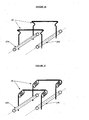
- the guide may also be designed as shown schematically in Figure 27, with two branches (13) and (14), or a single branch (13), so as to provide an area where the rollers (21) and (22) do not are not in contact with the rolling path (11). This provision will in particular be provided for the zones corresponding to the beginning of opening (or end of closing) of the door.
- the mechanism (9) will in this case be provided with guide slides (91) and (92) shown diagrammatically in FIG. 28, to guide the branches (13) and (14) and ensure a smooth connection between the rollers ( 21) and (22), and the guide (1) when maneuvering the door.
- the sliders (91) and (92) will not be detailed here, but may be made so that their shapes partly follow the contours of the sections of the branches (13) and (14), and so as to present a coefficient of friction reduced.
- a variant may consist in providing for the mounting of the sliders (91) and (92) to the same sheet of the door (or the body).
- the guide (1) can be bent at its free end, as shown schematically in FIG. 24, so as to constitute an abutment for the roller (4) - or for the rollers (21) and (22) - thus making it possible to limit the travel of the door to the "full open" position.
- the guide (1) may be constituted by a plate integral with the body (or the door), on which the rollers (21) and (22) will bear.
- the roller (4) may be retained to oppose the force generated by the rollers (21) and (22). However, if the guide plate (1) is sufficiently rigid, the roller (4) will not be necessary.
- the rollers (21) and (22) will have an approximately circular trajectory, centered on the axis of the joints between the door and the bodywork. Openings (15) or bosses (16) may be provided on the path of the rollers (21) and (22) in order to eliminate the blocking function in certain sectors of its race.
- Shapes connection zones (151) - (152) or (161) - (162) are provided so as to avoid jolts during the path of the rollers (21) and (22) in their path.
- the shape of the carriage (2) will be exposed here only schematically and can be optimized for each specific application case, especially to meet the dimensional constraints of its environment. ( Figure 2).
- the carriage (2) may be made of metal, plastic or synthetic material and will have the function of ensuring a sufficiently rigid connection between the elements that it supports. It can be obtained, as such, by molding, injection, forging, stamping or any other conventional method.
- the carriage (2) is fixed to the door (or the body) by any means known in the current state of the art. (Screwing, bolting, crimping, welding,).
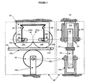
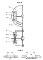
- the carriage (2) comprises ( Figure 1):
- the brake rollers (21) and (22), mounted respectively on their axes (23) and (24), are provided with a generally cylindrical shape, made of material allowing elastic deformation (elastomer, rubber or materials used in the production of tires ).
- the role of the brake rollers (21) and (22) is to ensure, when they are in contact with the guide (1), a relative locking between the guide (1) and the mechanism (9).
- the diameters of the rollers-brakes (21) and (22) will be identical in principle; however, it may slightly differ, in the case where it is desired to introduce a slight asymmetry in the opening and closing forces of the door.
- the material in which the rollers (21) and (22) will be made will be more or less soft, so as to ensure, by elastic deformation, a slight rolling resistance force during the opening and closing maneuvers.
- the material constituting the treads (211) and (221) of the rollers (21) and (22), if it is different from the material constituting the body of the rollers, will be chosen so as to guarantee a sufficient friction force with respect to in the guide (1) and a longevity in accordance with the specifications of the envisaged applications.
- the treads (211) and (221) of the rollers (21) and (22) may be smooth, or carved patterns to ensure better adhesion relative to the rolling path (11).
- the treads (211) and (221) may include notches of any shape, corresponding to a notching of the rolling path (11) of the guide (1).
- the tread sections (211) and (221) will be a shape in correspondence with that of the rolling path (11), ( Figure 25), with the purpose of optimizing the guidance of the rollers (21) or (22) relative to the guide (1).
- the rollers (21) and (22) may be mounted so that they rotate freely about their respective axes, or on the contrary so that the rollers are integral with the axes. The arbitration between one or the other solution will be based on economic considerations and / or functional longevity of the assembly.
- the blocking of the axial movement of the axes (23) and (24) relative to the carriage (2) can be achieved by any conventional means: washers and circlips or pins on either side of the lateral openings of the carriage, shoulders at the level axis, not shown in the accompanying illustrations.
- the axes (23) and (24) are integral with the rollers (21) and (22), themselves “prisoners" of the carriage (2), it will not be necessary to provide an axial locking. In this case, it may be useful to provide shoulders (212) - (213) and (222) - (223) on both sides of the rollers (21) and (22), in order to limit the forces friction between the latter and the side walls of the carriage (2). ( Figure 3).
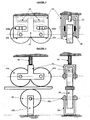
- Lateral guide openings (25), (26), (27) and (28) formed in the body of the carriage (2) are intended to hold and guide the axes (23) and (24) of the rollers ( 21) and (22), in particular during door opening and closing maneuvers. These guiding openings will be designed so that they have bosses and notches, to produce the effects described below. ( Figures 4 and 11).
- the axes (23) and (24) move in the lateral guide openings (25), (26), (27) and (28).
- sliders respectively (233) - (234) and (243) - (244), may optionally be mounted on the axes (23) and (24), so as to allow a better guidance and an increase in the longevity of the whole. ( Figure 15).
- the slides may be made of a material that offers low friction characteristics relative to the material constituting the body of the carriage (2).
- the guide apertures (25), (26), (27) and (28) may be obtained by any method known in the state of the art (for example by cutting if it is a part metallic or by injection in the case of a plastic part).
- the surface state of the zones in contact with the axes (23) and (24) or with the slides (233) - (234) and (243) - (244) will be such that there have no premature wear.
- the contour of the lateral guide openings (25), (26), (27) and (28) may be coated with a material promoting sliding and guaranteeing the longevity of the assembly.
- the axes (23) and (24) are kept at a constant distance via a connecting element (5).
- the spacing between the axes will be very slightly less than the sum of the radii of the rollers (21) and (22), so that the latter are permanently maintained in compression against each other, thus preventing their rotation when they are both in contact with the guide (1).
- This arrangement ensures the relative locking between the carriage (2) and the guide (1).
- the lateral openings (25a) - (27a) and (26a) - (28a), will comprise bosses (251a) - (271a) and (261a) - (281a), intended to offer a slight resistance to the displacement of the axes (23a). ) and (24), during the opening or closing maneuvers, allowing, among other things, to calibrate the force required for unlocking and to determine the travel of the door that is desired, between the locked positions and unlocked. ( Figure 32).
- the lateral guiding apertures (25a), (26a), (27a) and (28a), will further comprise bosses (252a) - (272a) and (262a) - (282a) ( Figure 4), designed so as to generating, during the opening or closing maneuvers, a displacement of one of the axes (23) or (24), in a direction perpendicular to the guide (1), which causes a slight lifting of one of the rollers (21) or (22) relative to the guide, allowing the rotation of the other roller which is it, remained in contact with the guide (1). It should be noted that the roller thus lifted is also rotated, in the opposite direction, but no longer has any lock with respect to the guide. ( Figure 31).
- the ramps respectively (2521a) - (2522a), (2621a) - (2622a), (2721a) - (2722a) and (2821a) - (2822a) bosses (252a), (262a), (272a) and (272a) 282a) will be, by nature, asymmetrical. ( Figure 4).
- the lateral openings (25a) - (27a) and (26a) - (28a) also have notches (253a) - (273a) and (263a) - (283a), in which the axes ( 23) and (24), during the opening and closing operations of the door.
- the force exerted by the elastic element (3) on the axis (23) or (24) thus accommodated in two of the notches (253a) - (273a) or (263a) - (283a), is partly counterbalanced by the rolling resistance force of the roller (21) or (22) on the guide (1).
- the elastic assembly (3) tends to extract the axis (23) or (24) from the notches respectively (253a) - (273a) ) or (263a) - (283a), to return it to its locked initial position.
- the rollers (21) and (22) are then again in contact with the guide (1) and ensure the relative locking between the carriage (2) and the guide (1).
- This re-locking operation from the position where it has ceased to exert an effort to open or close the door, is accompanied by a limited relative movement between the door and the body. This displacement is determined by the dimensions of the guide openings (25a), (26a), (27a) and (28a). This makes it easy to immobilize the door in any position that one chooses by performing the maneuver. The door is locked automatically as soon as one stops exerting an effort of opening or closing, without it being necessary to search for a predefined detent position.
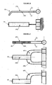
- the connecting element (5) can be either directly connected to the door (or to the body) if the material constituting it has elastic properties, or via an elastic element (deformable fastening tab (6) shown schematically in FIG. 6 or block of elastic material (7) shown schematically in FIG. 7). In one or the other of these cases, when a force is exerted on the door, the assembly formed by the rollers (21) - (22) and the connecting element (5), starts to tilt , (FIG.
- the fixing lug (6) will be made of material having elastic deformability characteristics. (Metal, injected plastic, synthetic material, ).
- the geometric shape of the fixing lug (6) will be provided in such a way that the main deformation acts in a direction parallel to the guide (1), so as to ensure the necessary movement of the rollers (21) and (22) between the positions "Locked” and "unlocked".
- the service thus obtained is simpler, because it is necessary to maintain a constant effort corresponding to the unlocking force during the entire maneuver. In return, we realize the economy of the body of the carriage (2).
- the axes (23) and (24) are maintained only by the guiding openings (25b), (26b), (27b) and (28b) of the carriage (2), and undergo the forces produced by the elastic element (3), which tends to bring them towards one another.
- the axes (23) and (24) can however deviate, so that the rollers (21) and (22) are no longer in contact with each other and that their rotation (in the same direction) in contact with the guide (1) thus become possible, thereby allowing relative movement between the carriage (2) and the guide (1).
- Figure 34 ).
- the guide openings (25b), (26b), (27b) and (28b) have bosses (251b), (261b), (271b) and (281b), ( Figure 11), which constitute a displacement resistance axes (23) and (24), allowing, among other things, to calibrate the force required for unlocking and to determine the travel of the door that is desired between the locked and unlocked positions.
- Figure 35 It should be noted that the elasticity of the constituent material of the rollers participates in the calibration of the unlocking force, a slight "crushing" of the rollers (21) and (22) against the guide (1) being necessary for the respective axes (23) and (24) cross the bosses, respectively (251b) - (271b), or (261b) - (281b).
- the guide openings (25b), (26b), (27b) and (28b), furthermore have notches (252b), (262b), (272b) and (282b), (FIG. accommodate the axes (23) or (24), depending on whether one is opening or closing the door.
- the ramps respectively (2511b) - (2512b), (2611b) - (2612b), (2711b) - (2712b) and (2811b) - (2812b) bosses (251b), (261b), (271b) and (281b) ), can be slightly asymmetrical, so as to differentiate the locking and unlocking efforts.
- the guide openings (25b), (26b), (27b) and (28b) have ends (253b), (263b), (273b) and (283b), ( Figure 11), constituting stops for limiting the stroke of one of the axes (23) or (24), depending on whether one is opening or closing, thereby ensuring the separation of the rollers (21) and (22).
- the elastic assembly (3) tends to spontaneously return the axes (23) and (24) to their positions initials "lock".
- the rollers (21) and (22) are then again in contact with each other and put in slight compression by the elastic assembly (3). This re-locking operation, from the position where it has ceased to exert an effort to open or close the door, is accompanied by a limited relative movement between the door and the body.
- This deflection is determined by the dimensions of the guide openings (25b), (26b), (27b) and (28b). This makes it easy to immobilize the door in any position that one chooses by performing the maneuver. In addition, the setting of the door is done automatically when it ceases to exert an effort of opening or closing, without the need to search for a predefined detent position.
- permanent magnets or any magnetic materials
- (254), (264), (274) may be considered , (284), at the respective notches (253a), (263a), (273a), (283a), or (252b), (262b), (272b), (282b).
- the attachment mode of the magnets is not specified here, but can be achieved by all means known in the current state of the art. (Crimping, gluing, screwing or other).
- the axes (23) and (24) of the rollers (21) and (22) will necessarily be made of a material to benefit from the effect of permanent magnets: ferrous metals, magnetic materials.
- An additional option may be to add parts (231), (232), (241), and (242), having the above properties, to the ends of the axes (23) and (24), as illustrated in Figures 9 and 13, so that the parts; respectively (231), (232), (241), and (242) are opposite permanent magnets respectively (254), (274), (264) and (284).
- a possible variant will be to make the pieces (231), (232), (241), and (242) of magnetic materials and to provide cleats (255), (265), (275) and (285), at respective notches (253a), (263a), (273a) and (283a), or (252b), (262b), (272b) and (282b).
- the cleats (255), (265), (275) and (285) may be made of the same material as the body of the carriage (2), provided that the latter is made from a material to enjoy of the magnetization effect.
- the cleats (255), (265), (275) and (285) may, for example, be made by simple cutting and folding of a portion of side faces of the carriage (2).
- the function of the roller (4) will be to counterbalance the effort sustained by the guide (1) from the carriage (2), thus ensuring the maintenance of the guide (1) during its relative movement through the mechanism (9) . ( Figure 1).
- the roller (4) will be free to rotate about an axis (41).
- the axis (41) will be mounted on the support (42), itself integral with the carriage (2), or may be directly integral with a door element (or body).
- the axial locking of the shaft (41) relative to the support (42) can be achieved by any conventional means: circlip, pin, shoulder at the axis, not shown in the illustrations, attached.
- the connecting element (5) (FIG. 18) is intended to keep the axes (23) and (24) of the rollers (21) and (22) at a constant distance, without interfering with the relative mobility of these axes in the lateral guide openings (25), (26), (27) and (28)
- the shape of the connecting element (5) will only be exposed here schematically and can be optimized for each specific application case , especially to meet the dimensional constraints of its environment.
- This connecting element may consist of a single piece ( Figure 18), made of plastic, metal, synthetic material, and obtained by any means known in the state of the art. (molding, injection, forging, stamping or any other conventional method).
- the connecting element (5) will be provided with two lateral flanks (51) and (52), having orifices (511) - (512) and (521) - (522) for receiving the axes (23) and (24). ).
- a simplified variant of the element (5) is shown schematically in FIG. to retain only the two lateral flanks (51) and (52), not interconnected, and having orifices (511) - (512) and (521) - (522) for receiving the axes (23) and (24) ).
- the blocking of the axial movement of the axes (23) and (24) with respect to the connecting element (5) can be achieved by any conventional means: circlip, pin, shoulder at the axis, not shown on the illustrations attached.
- the connecting element (5) may simply be "enclosed” within the carriage (2), so that it is not essential to provide axial locking of the axes (23) and (24). ( Figure 20).
Landscapes
- Engineering & Computer Science (AREA)
- Mechanical Engineering (AREA)
- Operating, Guiding And Securing Of Roll- Type Closing Members (AREA)
- Support Devices For Sliding Doors (AREA)
- Lock And Its Accessories (AREA)
- Handcart (AREA)
- Hinge Accessories (AREA)
- Wing Frames And Configurations (AREA)
- Freezers Or Refrigerated Showcases (AREA)
- Respiratory Apparatuses And Protective Means (AREA)
- Passenger Equipment (AREA)
Claims (8)
- Türarretierung in nicht vorbestimmten Anhaltpositionen zwischen der Schließung und vollen Öffnung, bestehend aus einer beweglichen Türführung (1), verankert mit einem feststehenden Teil (Karosserie) oder einem mobilen Teil (Tür), einerseits, und einem, mit dem anderen Teil (Tür oder Karosserie) verankerten, Mechanismus (9) andererseits, sodass die Führungseinheit (1), durch ein relatives Verschieben zwischen den beiden Elementen, in dem Mechanismus (9) einlaufen kann; die Beibehaltung der Position wird mit einer Blockierung der Relativbewegung der Führungseinheit (1) durch Mechanismus (9) gesichert, wobei die Einheit folgende Eigenschaften vorweist:einerseits, eine Führungseinheit (1) mit einer Rollstrecke und Blockierung der Relativbewegung zwischen der besagten Führungseinheit und dem Mechanismus (9), wobei die Oberfläche der Rollstrecke (11) genügend aufgeraut sein muss, um die Haftbeständigkeit mit den Rollen (21) und (22) für die Blockierung zu gewährleisten, und könnte hierzu mit Riffelungen jeglicher Art ausgestattet sein, die mit einer eventuellen Riffelung der Rollbänder der Rollen (21) und (22) übereinstimmen müssen, wobei die besagten Rollen mit einem mehr oder weniger weichen Werkstoff ausgestattet sind, um eine gute Haftbeständigkeit zwischen ihnen beiden und der Führungseinheit (1) zu sichern;andererseits, einen Mechanismus (9), bestehend aus einem Fahrgestell (2) mit 2 nebeneinander liegenden Bremsrollen (21) und (22), die Beide mit der Führungseinheit (1) in Kontakt sind und mit zwei Achsen (23) und (24) ausgestattet sind, die innerhalb der, in dem Fahrgestell (2) vorgesehenen seitlichen Führungsöffnungen (25), (26), (27) und (28), gleiten, wobei die elastische Einheit (3) direkt oder indirekt auf die Achsen (23) und (24) wirkt, und die Positionsbeibehaltung oder das Rückfahren der Rollen (21) und (22) in die verriegelte Position sichert; Position in der die Rollen (21) und (22) mit der Führungseinheit (1) in Kontakt sind und leicht gegeneinander unter Druck stehen, was die Blockierung dieser Rollen (21) und (22) gegenüber der Führungseinheit (1) zur Folge hat; die Kraft, die von den Rollen (21) und (22) auf dieser Führungseinheit ausgeübt wird, wird von einer Rolle (4), die gegenüber den Rollen (21) und (22) montiert wurde, ausgeglichen, und garantiert so die Positionsbeibehaltung der Führungseinheit (1) während der relativen Verschiebung im Mechanismus (9), besagter Mechanismus mit folgenden drei Funktionen:a) Blockierung in Rotation der Bremsrollen (21) und (22) gegen die Führungseinheit (1), in nicht vorbestimmter Position,b) Freigabe zur Rotation der Rollen (21) und (22), wenn auf die Tür eine Kraft zum Öffnen oder Schließen ausgeübt wird, die stärker als ein vorbestimmter Schwellwert ist; diese Entriegelung wird von einem leichten Ausschlag zwischen Mechanismus (9) und Führungseinheit (1) begleitet,c) automatisches Rückfahren in "verriegelter" Situation, in eine nicht vorbestimmte Öffnungsposition, wenn die Antriebskraft nachlässt;die seitlichen Führungsöffnungen (25), (26), (27) und (28), versehen mit Nocken und Kerben, die, während den Verschiebungen der Achsen (23) und (24) Widerstandspunkte darstellen, sowie auch stabile Positionen, die jeweils den "Entriegelungsphasen", und den Phasen der Manipulationen zum Öffnen und Schließen entsprechen, wobei die besagten Nocken und Kerben zeichnerisch so vorgesehen wurden, dass die Verschiebungen der Achsen (23) und (24) eine Positionierung der Rollen (21) und (22) in einer der 2 folgenden Konfigurationen zur Folge haben, und die Entriegelung ermöglichen:a) die Rollen (21) und (22) bleiben, mit Hilfe eines Verbindungselementes (5) ständig in Kontakt miteinander, wobei die Entriegelung erfolgt, wenn eine der Rollen etwas von der Führungseinheit (1) entfernt wird, zur Freigabe der Rotation der anderen Rolle in Kontakt mit der Führungseinheit, und folglich der relativen Bewegung zwischen Fahrgestell (2) und Führungseinheit (1);b) die Rollen (21) und (22) sind unabhängig von einander, bleiben aber ständig in Kontakt mit der Führungseinheit (1), dank der Form und Position der seitlichen Führungsöffnungen; die Entriegelung erfolgt wenn die 2 Rollen leicht von einander getrennt sind, um eine freie Rotation entlang des Führungselementes zu ermöglichen, sowie auch hier die Relativbewegung zwischen Fahrgestell (2) und Führungseinheit (1);während die elastische Einheit (3) einen Druck auf die Achsen (23) und (24) ausübt, was eine Näherung dieser Beiden in verriegelter Zentralposition zur Folge hat, und ein seitliches Verschieben der Achsen (23) und (24) entlang der Führungsöffnungen (25), (26), (27) und (28) hindert, sodass, wenn die Manipulation nachlässt, die Achsen spontan wieder in ihre Ruheposition zurückfahren; Rollen (21) und (22) sind gegeneinander blockiert, in Kontakt mit Führungseinheit (1); der Türausschlag während dieser Wieder-Verriegelung ist durch die Dimensionen der seitlichen Führungsöffnungen (25), (26), (27) und (28) begrenzt; ist ein Verbindungselement (5) für die Positionsbeibehaltung der Rollen (21) und (22) vorgesehen, so wird die elastische Einheit (3) direkt auf dieses Verbindungselement (5) wirken können.
- Türarretierung nach Patentanspruch 1, charakterisiert mit dem Verbindungselement (5), vorgesehen für die Positionsbeibehaltung der Achsen (23) und (24), entweder direkt mit der Tür (oder der Karosserie) verankert, wenn es in einem Werkstoff mit elastischen Eigenschaften, der eine leichte Verformung zulässt, hergestellt wurde, oder aber mit einem elastischen Element als Zwischenelement - verformbare Befestigungsklaue (6) oder Block aus elastischem Werkstoff (7) - das, wenn eine Kraft auf die Tür zum Öffnen oder Schließen ausgeübt wird, ein Kippen der Einheit, bestehend aus den Rollen (21)-(22) und dem Verbindungselement (5) zulässt, was das Lösen einer der Rollen (21) oder (22) im Verhältnis zur Führungseinheit (1) zur Folge hat, und somit die Freigabe der Relativbewegung der Einheit Rollen (21)-(22) im Verhältnis zur Führungseinheit (1); wenn die Kraft nachlässt, lassen die Befestigungsklaue (6) oder der elastische Block (7) automatisch die Einheit Rollen (21)-(22) wieder in Kontakt der Führungseinheit (1) kommen , um somit die Relativbewegung zwischen Rollen (21)-(22) und Führungseinheit (1) zu blockieren.
- Türarretierung nach Patentanspruch 1, charakterisiert mit Träger (42) der Rolle (4), integriert in das Fahrgestell (2) um eine einziges Teil zu bilden.
- Türarretierung nach Patentanspruch 1, charakterisiert mit magnetischen Werkstoffen, die auf den seitlichen Führungsöffnungen (25), (26), (27) und (28), oder auf den Achsen (23) und (24) positioniert sind, um die Positionsbeibehaltung der Achsen (23) und (24) in ihren Kerben bei den Manipulationen der Tür zum Öffnen oder Schließen, zu verstärken.
- Türarretierung nach Patentanspruch 1, charakterisiert mit dem Bereich der Rollbänder der Rollen (21) und (22) in verschiedenen Formen (U-Form, V-Form, umgedrehte V-Form, Doppelbahnstrecke,...) zur Verbesserung der Führung, wobei die Rollstrecke (11) von Führungseinheit (1) ebenfalls der entsprechenden Konfiguration angepasst wird.
- Türarretierung nach Patentanspruch 1, charakterisiert mit Führungseinheit (1) mit zwei Armen (13) und (14) oder einem Arm (13), um einen Bereich auszusparen, wo die Rollen (21) und (22) nicht in Kontakt mit der Rollstrecke (11) sind, wobei die Arme (13) und (14) mit Führungsgleitfüssen (91) und (92) geführt werden können.
- Türarretierung nach Patentanspruch 1, charakterisiert mit Führungseinheit (1) bestehend aus einer Platte die mit der Karosserie (oder der Tür) verankert ist, und die die Rollen (21) und (22) aufliegen, die während der Manipulationen zum Öffnen und Schließen eine fast runde Strecke zurücklegen, und hauptsächlich auf die Achse der Gelenke zwischen Tür und Karosserie zentriert sind.
- Türarretierung nach Patentanspruch 1, charakterisiert mit seitlichen Führungsöffnungen (25), (26), (27) und (28), die woanders als auf den Achsen (23) und (24) positioniert sind, wobei die Positionsbeibehaltung der Rollen (21) und (22) durch ein Verbindungselement (5) gewährleistet ist, das mit Führungsgleitfüssen ausgestattet ist, die in den Führungsöffnungen positioniert sind.
Applications Claiming Priority (2)
| Application Number | Priority Date | Filing Date | Title |
|---|---|---|---|
| FR0408669A FR2874051B1 (fr) | 2004-08-05 | 2004-08-05 | Arret de porte a positions de maintien indeterminees |
| PCT/FR2005/001901 WO2006024736A1 (fr) | 2004-08-05 | 2005-07-22 | Arret de porte a positions de maintien indeterminees |
Publications (2)
| Publication Number | Publication Date |
|---|---|
| EP1789644A1 EP1789644A1 (de) | 2007-05-30 |
| EP1789644B1 true EP1789644B1 (de) | 2008-01-23 |
Family
ID=34954876
Family Applications (1)
| Application Number | Title | Priority Date | Filing Date |
|---|---|---|---|
| EP05793676A Expired - Lifetime EP1789644B1 (de) | 2004-08-05 | 2005-07-22 | Türstopper mit unbestimmten haltepositionen |
Country Status (8)
| Country | Link |
|---|---|
| US (1) | US7578029B2 (de) |
| EP (1) | EP1789644B1 (de) |
| JP (1) | JP4825801B2 (de) |
| CN (1) | CN100504015C (de) |
| AT (1) | ATE384843T1 (de) |
| DE (1) | DE602005004561T2 (de) |
| FR (1) | FR2874051B1 (de) |
| WO (1) | WO2006024736A1 (de) |
Families Citing this family (19)
| Publication number | Priority date | Publication date | Assignee | Title |
|---|---|---|---|---|
| FR2889234B1 (fr) * | 2005-07-27 | 2007-11-23 | Andre Prieur | Arret de porte a positions de maintien indeterminees |
| WO2010092349A1 (en) * | 2009-02-16 | 2010-08-19 | Corcost Limited | Arrestor |
| FR2960585B1 (fr) * | 2010-05-26 | 2012-07-06 | Andre Prieur | Dispositif d'arret de porte |
| FR2966185B1 (fr) * | 2010-10-19 | 2012-10-26 | Peugeot Citroen Automobiles Sa | Systeme d'arret pour un ouvrant de vehicule. |
| FR2981108B1 (fr) * | 2011-10-11 | 2013-11-08 | Andre Prieur | Dispositif d'arret de porte |
| CN102797399B (zh) * | 2012-08-16 | 2015-06-24 | 广州市粤兴铝业有限公司 | 吊挂式推拉门防晃动装置 |
| KR20160075544A (ko) | 2013-10-01 | 2016-06-29 | 워렌 인더스트리즈 엘티디. | 차량 도어 제어 시스템 |
| JP6237679B2 (ja) * | 2015-03-19 | 2017-11-29 | 株式会社豊田自動織機 | 車両用ドア構造 |
| FR3046193A1 (fr) * | 2015-12-24 | 2017-06-30 | Andre Roland Prieur | Dispositif d'arret de porte a positions de maintien multiples |
| CN106050040B (zh) * | 2016-07-22 | 2017-10-24 | 佛山市柏茨装饰墙体技术有限公司 | 一种具有制动结构的滑轮 |
| US10533603B2 (en) | 2017-03-02 | 2020-01-14 | Bell Helicopter Textron Inc. | Roller track assembly for a tiltrotor proprotor door |
| US10994853B2 (en) | 2017-03-02 | 2021-05-04 | Bell Helicopter Textron Inc. | Tiltrotor aircraft rotating proprotor assembly |
| US11046446B2 (en) | 2017-03-02 | 2021-06-29 | Bell Helicopter Textron Inc. | Tiltrotor aircraft rotating proprotor assembly |
| US10539180B2 (en) | 2017-03-02 | 2020-01-21 | Bell Helicopter Textron Inc. | Bogie mechanism for a tiltrotor proprotor door |
| FR3074829A1 (fr) * | 2017-12-13 | 2019-06-14 | Andre Roland Prieur | Dispositif d'arret de porte a positions de maintien infinies |
| CN108104626A (zh) * | 2017-12-22 | 2018-06-01 | 丰业迪睦斯(芜湖)汽车部件有限公司 | 一种小型汽车用车门限位器 |
| US10875627B2 (en) | 2018-05-01 | 2020-12-29 | Bell Helicopter Textron Inc. | Movable cover for a proprotor nacelle |
| US20200270919A1 (en) * | 2019-02-21 | 2020-08-27 | Marathonnorco Aerospace, Inc. | Hold Open Rod Having a Lock Mechanism for Securely Locking the Hold Open Rod in an Extended Configuration |
| CN115434597B (zh) * | 2022-09-29 | 2025-04-22 | 福建汉特云智能科技有限公司 | 一种机器人柜体开门结构 |
Family Cites Families (11)
| Publication number | Priority date | Publication date | Assignee | Title |
|---|---|---|---|---|
| DE29611819U1 (de) * | 1996-07-06 | 1996-09-05 | Friedr. Fingscheidt GmbH, 42551 Velbert | Rastvorrichtung insbesondere für Fahrzeug-Türhalter |
| DE19632630C2 (de) * | 1996-08-13 | 1998-09-10 | Bayerische Motoren Werke Ag | Feststellvorrichtung für eine Tür oder eine Klappe eines Kraftfahrzeugs |
| US6681444B2 (en) * | 1997-03-17 | 2004-01-27 | Automotive Technologies International, Inc. | Apparatus for controlling a door |
| US6065185A (en) * | 1998-03-17 | 2000-05-23 | Automotive Technologies International Inc. | Vehicle infinite door check |
| DE19758302A1 (de) * | 1997-12-31 | 1999-07-01 | Fhp Motors Gmbh | Verstellvorrichtung für einen Öffnungsabschluß |
| US6467126B1 (en) | 2000-07-21 | 2002-10-22 | Daimlerchrysler Corporation | Door check mechanism providing an infinite number of stable positions |
| US6513193B1 (en) | 2000-07-21 | 2003-02-04 | Daimlerchrysler Corporation | Door check mechanism providing an infinite number of stable positions |
| US6370732B1 (en) | 2000-09-06 | 2002-04-16 | Daimlerchrysler Corporation | Door check mechanism providing an infinite number of stable positions |
| EP1249569B1 (de) * | 2001-04-13 | 2004-02-04 | Gammastamp S.p.A. | Stossdämpfender Türfeststeller für Fahrzeuge |
| JP2004316299A (ja) | 2003-04-17 | 2004-11-11 | Riken Kaki Kogyo Kk | 自動車用ドアチェッカ |
| FR2889234B1 (fr) * | 2005-07-27 | 2007-11-23 | Andre Prieur | Arret de porte a positions de maintien indeterminees |
-
2004
- 2004-08-05 FR FR0408669A patent/FR2874051B1/fr not_active Expired - Fee Related
-
2005
- 2005-07-22 AT AT05793676T patent/ATE384843T1/de not_active IP Right Cessation
- 2005-07-22 WO PCT/FR2005/001901 patent/WO2006024736A1/fr not_active Ceased
- 2005-07-22 JP JP2007524366A patent/JP4825801B2/ja not_active Expired - Fee Related
- 2005-07-22 CN CNB2005800264441A patent/CN100504015C/zh not_active Expired - Fee Related
- 2005-07-22 EP EP05793676A patent/EP1789644B1/de not_active Expired - Lifetime
- 2005-07-22 US US11/573,044 patent/US7578029B2/en not_active Expired - Fee Related
- 2005-07-22 DE DE602005004561T patent/DE602005004561T2/de not_active Expired - Lifetime
Also Published As
| Publication number | Publication date |
|---|---|
| CN1993531A (zh) | 2007-07-04 |
| CN100504015C (zh) | 2009-06-24 |
| FR2874051B1 (fr) | 2006-09-08 |
| DE602005004561D1 (de) | 2008-03-13 |
| ATE384843T1 (de) | 2008-02-15 |
| JP4825801B2 (ja) | 2011-11-30 |
| JP2008509301A (ja) | 2008-03-27 |
| FR2874051A1 (fr) | 2006-02-10 |
| WO2006024736A1 (fr) | 2006-03-09 |
| US20080066259A1 (en) | 2008-03-20 |
| US7578029B2 (en) | 2009-08-25 |
| DE602005004561T2 (de) | 2009-01-29 |
| EP1789644A1 (de) | 2007-05-30 |
Similar Documents
| Publication | Publication Date | Title |
|---|---|---|
| EP1789644A1 (de) | Türstopper mit unbestimmten haltepositionen | |
| EP0947380B1 (de) | Auf dem Schienenboden eingebaute Zahnstangenvorrichtung | |
| EP3020996B1 (de) | Schwimmsattelbremse, die eine zentrale elastische rückholfeder eines externen bremsbelags umfasst, die ausgleichsmittel des verschleissspiels umfasst, feder und ersatzteilkit | |
| EP3006763B1 (de) | Elastische rückholfeder eines bremsbelags, die ausgleichsmittel des verschleissspiels umfasst, scheibenbremse und ersatzteilkit | |
| EP0752338A1 (de) | Verriegelbare Schiene für Kraftfahrzeugsitze | |
| FR2881694A1 (fr) | Mecanisme de guidage en translation avec blocage en position notamment pour des elements ajustables d'un siege de vehicule automobile | |
| EP0863043A1 (de) | Kraftfahrzeugsitzschiene | |
| FR2987249A1 (fr) | Chariot motorise et installation d'occultation comprenant un tel chariot | |
| FR2963586A1 (fr) | Glissiere pour siege de vehicule automobile a verrouillage lateral sans jeu | |
| EP2773830B1 (de) | Türstoppvorrichtung | |
| EP1920127B1 (de) | Türstopper mit unbestimmten haltepositionen | |
| FR2666616A1 (fr) | Dispositif de retenue pour un element mobile pivotant, notamment pour une porte d'un vehicule. | |
| EP1136313A1 (de) | Verstelleinheit für Kopfstütze | |
| FR2796013A1 (fr) | Mecanisme de reglage de glissiere de siege de vehicule automobile et siege equipe d'un tel mecanisme | |
| FR3016147A1 (fr) | Glissiere et siege de vehicule automobile comportant une telle glissiere | |
| FR2980510A3 (fr) | Dispositif de suspension et de coulissement pour portes coulissantes hermetiques | |
| FR3049536A1 (fr) | Structure d’assise reglable d’un siege de vehicule comportant un brin boucle de ceinture de securite. | |
| EP3030460B1 (de) | Abdeckanordnung für einen laderaum eines kraftfahrzeugs | |
| FR3057824A1 (fr) | Glissiere pour siege de vehicule, siege de vehicule comportant une telle glissiere | |
| FR2842767A1 (fr) | Glissiere pour siege de vehicule et siege equipe d'une telle glissiere | |
| FR3111854A1 (fr) | Dispositif de siège réglable en hauteur avec frein | |
| FR2931413A1 (fr) | Barre de galerie a moyens d'amortissement, et vehicule correspondant. | |
| WO2022058478A1 (fr) | Elément mobile pour tringle à rideau, et tringle comportant au moins un tel élément | |
| FR2979291A1 (fr) | Amortisseur de fin de course pour toit ouvrant de vehicule a commande manuelle. | |
| FR3087159A1 (fr) | Pare-soleil deployable et retractable de vehicule |
Legal Events
| Date | Code | Title | Description |
|---|---|---|---|
| PUAI | Public reference made under article 153(3) epc to a published international application that has entered the european phase |
Free format text: ORIGINAL CODE: 0009012 |
|
| 17P | Request for examination filed |
Effective date: 20070223 |
|
| AK | Designated contracting states |
Kind code of ref document: A1 Designated state(s): AT BE BG CH CY CZ DE DK EE ES FI FR GB GR HU IE IS IT LI LT LU LV MC NL PL PT RO SE SI SK TR |
|
| GRAP | Despatch of communication of intention to grant a patent |
Free format text: ORIGINAL CODE: EPIDOSNIGR1 |
|
| DAX | Request for extension of the european patent (deleted) | ||
| GRAS | Grant fee paid |
Free format text: ORIGINAL CODE: EPIDOSNIGR3 |
|
| GRAA | (expected) grant |
Free format text: ORIGINAL CODE: 0009210 |
|
| AK | Designated contracting states |
Kind code of ref document: B1 Designated state(s): AT BE BG CH CY CZ DE DK EE ES FI FR GB GR HU IE IS IT LI LT LU LV MC NL PL PT RO SE SI SK TR |
|
| REG | Reference to a national code |
Ref country code: GB Ref legal event code: FG4D Free format text: NOT ENGLISH |
|
| REG | Reference to a national code |
Ref country code: CH Ref legal event code: EP |
|
| REG | Reference to a national code |
Ref country code: IE Ref legal event code: FG4D Free format text: LANGUAGE OF EP DOCUMENT: FRENCH |
|
| REF | Corresponds to: |
Ref document number: 602005004561 Country of ref document: DE Date of ref document: 20080313 Kind code of ref document: P |
|
| GBT | Gb: translation of ep patent filed (gb section 77(6)(a)/1977) |
Effective date: 20080408 |
|
| NLV1 | Nl: lapsed or annulled due to failure to fulfill the requirements of art. 29p and 29m of the patents act | ||
| PG25 | Lapsed in a contracting state [announced via postgrant information from national office to epo] |
Ref country code: ES Free format text: LAPSE BECAUSE OF FAILURE TO SUBMIT A TRANSLATION OF THE DESCRIPTION OR TO PAY THE FEE WITHIN THE PRESCRIBED TIME-LIMIT Effective date: 20080504 Ref country code: FI Free format text: LAPSE BECAUSE OF FAILURE TO SUBMIT A TRANSLATION OF THE DESCRIPTION OR TO PAY THE FEE WITHIN THE PRESCRIBED TIME-LIMIT Effective date: 20080123 Ref country code: IS Free format text: LAPSE BECAUSE OF FAILURE TO SUBMIT A TRANSLATION OF THE DESCRIPTION OR TO PAY THE FEE WITHIN THE PRESCRIBED TIME-LIMIT Effective date: 20080523 |
|
| PG25 | Lapsed in a contracting state [announced via postgrant information from national office to epo] |
Ref country code: BG Free format text: LAPSE BECAUSE OF FAILURE TO SUBMIT A TRANSLATION OF THE DESCRIPTION OR TO PAY THE FEE WITHIN THE PRESCRIBED TIME-LIMIT Effective date: 20080423 Ref country code: AT Free format text: LAPSE BECAUSE OF FAILURE TO SUBMIT A TRANSLATION OF THE DESCRIPTION OR TO PAY THE FEE WITHIN THE PRESCRIBED TIME-LIMIT Effective date: 20080123 |
|
| PG25 | Lapsed in a contracting state [announced via postgrant information from national office to epo] |
Ref country code: PL Free format text: LAPSE BECAUSE OF FAILURE TO SUBMIT A TRANSLATION OF THE DESCRIPTION OR TO PAY THE FEE WITHIN THE PRESCRIBED TIME-LIMIT Effective date: 20080123 Ref country code: LV Free format text: LAPSE BECAUSE OF FAILURE TO SUBMIT A TRANSLATION OF THE DESCRIPTION OR TO PAY THE FEE WITHIN THE PRESCRIBED TIME-LIMIT Effective date: 20080123 Ref country code: PT Free format text: LAPSE BECAUSE OF FAILURE TO SUBMIT A TRANSLATION OF THE DESCRIPTION OR TO PAY THE FEE WITHIN THE PRESCRIBED TIME-LIMIT Effective date: 20080623 Ref country code: SI Free format text: LAPSE BECAUSE OF FAILURE TO SUBMIT A TRANSLATION OF THE DESCRIPTION OR TO PAY THE FEE WITHIN THE PRESCRIBED TIME-LIMIT Effective date: 20080123 |
|
| REG | Reference to a national code |
Ref country code: IE Ref legal event code: FD4D |
|
| PG25 | Lapsed in a contracting state [announced via postgrant information from national office to epo] |
Ref country code: NL Free format text: LAPSE BECAUSE OF FAILURE TO SUBMIT A TRANSLATION OF THE DESCRIPTION OR TO PAY THE FEE WITHIN THE PRESCRIBED TIME-LIMIT Effective date: 20080123 Ref country code: CZ Free format text: LAPSE BECAUSE OF FAILURE TO SUBMIT A TRANSLATION OF THE DESCRIPTION OR TO PAY THE FEE WITHIN THE PRESCRIBED TIME-LIMIT Effective date: 20080123 Ref country code: IE Free format text: LAPSE BECAUSE OF FAILURE TO SUBMIT A TRANSLATION OF THE DESCRIPTION OR TO PAY THE FEE WITHIN THE PRESCRIBED TIME-LIMIT Effective date: 20080123 Ref country code: DK Free format text: LAPSE BECAUSE OF FAILURE TO SUBMIT A TRANSLATION OF THE DESCRIPTION OR TO PAY THE FEE WITHIN THE PRESCRIBED TIME-LIMIT Effective date: 20080123 Ref country code: SE Free format text: LAPSE BECAUSE OF FAILURE TO SUBMIT A TRANSLATION OF THE DESCRIPTION OR TO PAY THE FEE WITHIN THE PRESCRIBED TIME-LIMIT Effective date: 20080423 Ref country code: SK Free format text: LAPSE BECAUSE OF FAILURE TO SUBMIT A TRANSLATION OF THE DESCRIPTION OR TO PAY THE FEE WITHIN THE PRESCRIBED TIME-LIMIT Effective date: 20080123 |
|
| PG25 | Lapsed in a contracting state [announced via postgrant information from national office to epo] |
Ref country code: RO Free format text: LAPSE BECAUSE OF FAILURE TO SUBMIT A TRANSLATION OF THE DESCRIPTION OR TO PAY THE FEE WITHIN THE PRESCRIBED TIME-LIMIT Effective date: 20080123 |
|
| PLBE | No opposition filed within time limit |
Free format text: ORIGINAL CODE: 0009261 |
|
| STAA | Information on the status of an ep patent application or granted ep patent |
Free format text: STATUS: NO OPPOSITION FILED WITHIN TIME LIMIT |
|
| 26N | No opposition filed |
Effective date: 20081024 |
|
| PG25 | Lapsed in a contracting state [announced via postgrant information from national office to epo] |
Ref country code: LT Free format text: LAPSE BECAUSE OF FAILURE TO SUBMIT A TRANSLATION OF THE DESCRIPTION OR TO PAY THE FEE WITHIN THE PRESCRIBED TIME-LIMIT Effective date: 20080123 |
|
| PG25 | Lapsed in a contracting state [announced via postgrant information from national office to epo] |
Ref country code: MC Free format text: LAPSE BECAUSE OF NON-PAYMENT OF DUE FEES Effective date: 20080731 |
|
| PG25 | Lapsed in a contracting state [announced via postgrant information from national office to epo] |
Ref country code: EE Free format text: LAPSE BECAUSE OF FAILURE TO SUBMIT A TRANSLATION OF THE DESCRIPTION OR TO PAY THE FEE WITHIN THE PRESCRIBED TIME-LIMIT Effective date: 20080123 |
|
| REG | Reference to a national code |
Ref country code: FR Ref legal event code: ST Effective date: 20090331 |
|
| PG25 | Lapsed in a contracting state [announced via postgrant information from national office to epo] |
Ref country code: CY Free format text: LAPSE BECAUSE OF FAILURE TO SUBMIT A TRANSLATION OF THE DESCRIPTION OR TO PAY THE FEE WITHIN THE PRESCRIBED TIME-LIMIT Effective date: 20080123 |
|
| PG25 | Lapsed in a contracting state [announced via postgrant information from national office to epo] |
Ref country code: FR Free format text: LAPSE BECAUSE OF NON-PAYMENT OF DUE FEES Effective date: 20080731 |
|
| REG | Reference to a national code |
Ref country code: CH Ref legal event code: PL |
|
| PG25 | Lapsed in a contracting state [announced via postgrant information from national office to epo] |
Ref country code: LI Free format text: LAPSE BECAUSE OF NON-PAYMENT OF DUE FEES Effective date: 20090731 Ref country code: CH Free format text: LAPSE BECAUSE OF NON-PAYMENT OF DUE FEES Effective date: 20090731 |
|
| PG25 | Lapsed in a contracting state [announced via postgrant information from national office to epo] |
Ref country code: HU Free format text: LAPSE BECAUSE OF FAILURE TO SUBMIT A TRANSLATION OF THE DESCRIPTION OR TO PAY THE FEE WITHIN THE PRESCRIBED TIME-LIMIT Effective date: 20080724 Ref country code: LU Free format text: LAPSE BECAUSE OF NON-PAYMENT OF DUE FEES Effective date: 20080722 Ref country code: BE Free format text: LAPSE BECAUSE OF NON-PAYMENT OF DUE FEES Effective date: 20080731 |
|
| PG25 | Lapsed in a contracting state [announced via postgrant information from national office to epo] |
Ref country code: TR Free format text: LAPSE BECAUSE OF FAILURE TO SUBMIT A TRANSLATION OF THE DESCRIPTION OR TO PAY THE FEE WITHIN THE PRESCRIBED TIME-LIMIT Effective date: 20080123 |
|
| PG25 | Lapsed in a contracting state [announced via postgrant information from national office to epo] |
Ref country code: GR Free format text: LAPSE BECAUSE OF FAILURE TO SUBMIT A TRANSLATION OF THE DESCRIPTION OR TO PAY THE FEE WITHIN THE PRESCRIBED TIME-LIMIT Effective date: 20080424 |
|
| PGFP | Annual fee paid to national office [announced via postgrant information from national office to epo] |
Ref country code: GB Payment date: 20130717 Year of fee payment: 9 |
|
| PGFP | Annual fee paid to national office [announced via postgrant information from national office to epo] |
Ref country code: IT Payment date: 20130709 Year of fee payment: 9 |
|
| GBPC | Gb: european patent ceased through non-payment of renewal fee |
Effective date: 20140722 |
|
| PG25 | Lapsed in a contracting state [announced via postgrant information from national office to epo] |
Ref country code: IT Free format text: LAPSE BECAUSE OF NON-PAYMENT OF DUE FEES Effective date: 20140722 |
|
| PG25 | Lapsed in a contracting state [announced via postgrant information from national office to epo] |
Ref country code: GB Free format text: LAPSE BECAUSE OF NON-PAYMENT OF DUE FEES Effective date: 20140722 |
|
| PGFP | Annual fee paid to national office [announced via postgrant information from national office to epo] |
Ref country code: DE Payment date: 20150710 Year of fee payment: 11 |
|
| REG | Reference to a national code |
Ref country code: DE Ref legal event code: R119 Ref document number: 602005004561 Country of ref document: DE |
|
| PG25 | Lapsed in a contracting state [announced via postgrant information from national office to epo] |
Ref country code: DE Free format text: LAPSE BECAUSE OF NON-PAYMENT OF DUE FEES Effective date: 20170201 |