EP1787041B1 - Agencement pour la fixation d'un mecanisme d'essuyage - Google Patents
Agencement pour la fixation d'un mecanisme d'essuyage Download PDFInfo
- Publication number
- EP1787041B1 EP1787041B1 EP05716444A EP05716444A EP1787041B1 EP 1787041 B1 EP1787041 B1 EP 1787041B1 EP 05716444 A EP05716444 A EP 05716444A EP 05716444 A EP05716444 A EP 05716444A EP 1787041 B1 EP1787041 B1 EP 1787041B1
- Authority
- EP
- European Patent Office
- Prior art keywords
- spacer
- shock absorber
- peripheral groove
- attachment tab
- absorber element
- Prior art date
- Legal status (The legal status is an assumption and is not a legal conclusion. Google has not performed a legal analysis and makes no representation as to the accuracy of the status listed.)
- Expired - Lifetime
Links
- 230000007246 mechanism Effects 0.000 title claims description 8
- 230000002093 peripheral effect Effects 0.000 claims abstract description 19
- 125000006850 spacer group Chemical group 0.000 claims abstract description 16
- 239000006096 absorbing agent Substances 0.000 claims abstract 8
- 230000035939 shock Effects 0.000 claims abstract 8
- 230000000284 resting effect Effects 0.000 claims abstract 2
- 230000000295 complement effect Effects 0.000 claims description 4
- 230000000903 blocking effect Effects 0.000 claims 1
- 238000007373 indentation Methods 0.000 claims 1
- 238000009434 installation Methods 0.000 claims 1
- 238000013016 damping Methods 0.000 description 26
- BASFCYQUMIYNBI-UHFFFAOYSA-N platinum Chemical compound [Pt] BASFCYQUMIYNBI-UHFFFAOYSA-N 0.000 description 3
- 230000007423 decrease Effects 0.000 description 2
- 230000007547 defect Effects 0.000 description 2
- 230000005489 elastic deformation Effects 0.000 description 1
- 239000013013 elastic material Substances 0.000 description 1
- 239000011521 glass Substances 0.000 description 1
- 230000002787 reinforcement Effects 0.000 description 1
Images

Classifications
-
- B—PERFORMING OPERATIONS; TRANSPORTING
- B60—VEHICLES IN GENERAL
- B60S—SERVICING, CLEANING, REPAIRING, SUPPORTING, LIFTING, OR MANOEUVRING OF VEHICLES, NOT OTHERWISE PROVIDED FOR
- B60S1/00—Cleaning of vehicles
- B60S1/02—Cleaning windscreens, windows or optical devices
- B60S1/04—Wipers or the like, e.g. scrapers
-
- B—PERFORMING OPERATIONS; TRANSPORTING
- B60—VEHICLES IN GENERAL
- B60S—SERVICING, CLEANING, REPAIRING, SUPPORTING, LIFTING, OR MANOEUVRING OF VEHICLES, NOT OTHERWISE PROVIDED FOR
- B60S1/00—Cleaning of vehicles
- B60S1/02—Cleaning windscreens, windows or optical devices
- B60S1/04—Wipers or the like, e.g. scrapers
- B60S1/043—Attachment of the wiper assembly to the vehicle
- B60S1/0441—Attachment of the wiper assembly to the vehicle characterised by the attachment means
- B60S1/0444—Attachment of the wiper assembly to the vehicle characterised by the attachment means comprising vibration or noise absorbing means
-
- F—MECHANICAL ENGINEERING; LIGHTING; HEATING; WEAPONS; BLASTING
- F16—ENGINEERING ELEMENTS AND UNITS; GENERAL MEASURES FOR PRODUCING AND MAINTAINING EFFECTIVE FUNCTIONING OF MACHINES OR INSTALLATIONS; THERMAL INSULATION IN GENERAL
- F16F—SPRINGS; SHOCK-ABSORBERS; MEANS FOR DAMPING VIBRATION
- F16F1/00—Springs
- F16F1/36—Springs made of rubber or other material having high internal friction, e.g. thermoplastic elastomers
Definitions
- the invention proposes an arrangement for mounting and fixing a wiper mechanism which comprises a damping element, making it possible to reduce the noise generated by the vibrations of the drive mechanism, as well as any positioning defects due to elastic deformations of the damping element.
- Current motor vehicles generally include a drive mechanism associated with each wiper blade, whether for wiping a rear transverse glass panel, or the front windshield of the vehicle.
- Each of these drive mechanisms comprises a drive shaft of the wiper blade which is rotated by an electric motor and which is guided in rotation by a bearing.
- the drive mechanism is fixed on a plate which is itself fixed at three points on a body structure element of the vehicle, so as to allow the immobilization of the wiper device, and to prevent its rotation relative to the glazed panel.
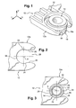
- Figures 1 to 3 an embodiment of the means used for mounting and fixing a support plate 10 on a vehicle body structure element.
- the plate 10 comprises for this purpose a horizontal fixing lug 12 which extends longitudinally forwards, and whose free front end 12a is fixed to a spacer 14 of the body structure element, via a damping element 16 made of an elastic material.
- the damping element 16 is a generally tubular shaped element, and its outer cylindrical wall 16e has a peripheral groove 18 against the bottom 22 of which the free end 12a of the bracket 12 is supported.
- the housing 20 is delimited by two concave sections 24, which are opposed axially, and which are complementary to the bottom 22 of the peripheral groove 18. These concave sections 24 cooperate with the bottom 22 of the peripheral groove 18, to achieve the positioning of the front end 12a of the lug 12 coaxially with the damping element 16.
- the housing 20 is also delimited by two longitudinal sections before 26, between which the damping element 16 is introduced into the housing 20.
- the average distance between the two longitudinal sections before 26 is smaller than the outer diameter of the bottom 22 of the peripheral groove 18 , so as to immobilize the damping element 16 in the housing 20.
- the housing 20 is delimited by a rear section 28 connecting the concave sections 24.
- the concave sections 24 and the rear section 28 form a single circular arc centered on the axis A of the spacer 14, and complementary to the bottom 22 of the peripheral groove 18.
- the damping element 16 is mounted tightly in the housing 20, which causes a radial deformation of the damping element 16.
- the damping element 16 can not therefore deform symmetrically with respect to its vertical axis A, which causes a radial offset of the fixing lug 12, and thus a positioning defect of the plate 10.
- the purpose of the invention is to propose an arrangement for mounting the plate, for which the mounting of the damping element in the housing 20 of the fixing lug 12 does not cause a radial offset of the fixing lug 12.
- the invention proposes an arrangement of the type described above, characterized in that there is a longitudinal clearance between the rear section and the bottom of the peripheral groove.
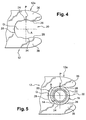
- FIG. 4 the front end 12a of a fastening lug 12 according to the invention, which comprises a housing 20 in which is received the bottom 22 of the peripheral groove 18 of the damping element 16.
- the housing 20 is delimited by two concave sections 24, by two longitudinal sections before 26, and a rear section 28 connecting the concave sections 24.
- the housing 20 is shaped so that there is a longitudinal clearance between the rear section 28 of the housing 20 and the bottom 22 of the groove 18.
- This clearance allows the damping element 16 to deform freely inside the volume 30 which is thus formed at the rear of the housing 20, and consequently, the damping element 16 deforms symmetrically with respect to its vertical axis A, improving the positioning of the bracket 12 coaxially to the same vertical axis A.
- the concave sections 24 are in the shape of a circular arc centered on the vertical axis A of the spacer 14. This makes it possible to have a large contact zone between the bottom 22 of the peripheral groove 18 and the concave sections 24.
- the concave sections 24 each comprise a radial recess 32 of transverse main axis, inside which the damping element 16 is able to deform, to further improve the positioning of the fixing lug 12.
- Each reinforcement 32 divides the associated concave section 24 into two segments 34 bearing against the bottom 22 of the groove 18.
- the segments 34 of the same concave section 24 are symmetrical with respect to a transverse axial plane P, that is to say that each concave section 24 has a symmetry with respect to this transverse axial plane. P.
- the housing 20 has a symmetry with respect to a longitudinal axial plane Q, that is to say that the two concave sections 24 are symmetrical with respect to this longitudinal axial plane Q.
- the distribution of the segments 34 ensures a symmetrical deformation of the damping element 16 inside the housing 20, thus not affecting the positioning of the fastening lug 12 relative to the vertical axis A.
- the longitudinal clearance between the rear portion 28 of the housing 20 and the bottom 22 of the groove 18 allows deformation of the damping element 16 in the volume 30 thus formed.
- the housing 20, which divides the front end 12a of the bracket 12 into two longitudinal branches 36 is extended longitudinally rearward, that is to say that this longitudinal clearance increases the length of the longitudinal branches 36.
- Increasing the length of the longitudinal branches 36 decreases the rigidity of the holding of the damping element 16 in the housing 20, and thus decreases the rigidity of the front end 12a of the bracket 12.
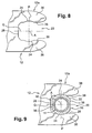
- the bottom 22 of the peripheral groove 18 comprises a flat portion 38 which extends in a transverse vertical plane vis-à-vis the rear section 28 of the housing.
- This flat part 38 makes it possible to have a rear section 28 that is generally rectilinear and has a transverse main orientation.
- this flat part 38 nevertheless requires angularly positioning the damping element 16 around the vertical axis A.
- the damping element 16 comprises two flat surfaces 38 which are symmetrical with respect to the vertical axis. AT.
Landscapes
- Engineering & Computer Science (AREA)
- Mechanical Engineering (AREA)
- General Engineering & Computer Science (AREA)
- Vibration Prevention Devices (AREA)
- Body Structure For Vehicles (AREA)
- Support Of The Bearing (AREA)
- Vibration Dampers (AREA)
- Cleaning In Electrography (AREA)
- Mutual Connection Of Rods And Tubes (AREA)
- Viewfinders (AREA)
- Cleaning Implements For Floors, Carpets, Furniture, Walls, And The Like (AREA)
- Fluid-Damping Devices (AREA)
- Clamps And Clips (AREA)
- Spinning Or Twisting Of Yarns (AREA)
- Arrangement Or Mounting Of Propulsion Units For Vehicles (AREA)
- Gyroscopes (AREA)
- Geophysics And Detection Of Objects (AREA)
- Vehicle Body Suspensions (AREA)
Description
- L'invention propose un agencement pour le montage et la fixation d'un mécanisme d'essuyage qui comporte un élément amortisseur, permettant de réduire le bruit généré par les vibrations du mécanisme d'entraînement, ainsi qui d'éventuels défauts de positionnements dus aux déformations élastiques de l'élément amortisseur.
- L'invention propose plus particulièrement un agencement pour le montage et la fixation d'une platine de support, notamment d'une platine de support d'un mécanisme d'essuie-glace, à un élément de structure de caisse d'un véhicule automobile, qui comporte :
- une entretoise, de forme globalement cylindrique de révolution d'axe principal vertical (A), qui est fixée à l'élément de structure de caisse, et
- une patte de fixation globalement horizontale qui est réalisée venue de matière avec la platine de support qui s'étend selon une direction principale longitudinale vers l'avant depuis la platine de support et dont l'extrémité longitudinale avant est fixée à l'entretoise par l'intermédiaire d'un élément amortisseur interposé entre la patte de fixation et l'entretoise,
- l'élément amortisseur est un élément de forme tubulaire coaxial à l'entretoise, dont la paroi cylindrique externe comporte une gorge périphérique contre le fond de laquelle la patte de fixation est en appui,
- l'extrémité avant de la patte de fixation comporte un logement en "C" dans lequel l'élément amortisseur est reçu, qui est délimité par deux tronçons concaves opposés et complémentaires du fond de la gorge périphérique, pour réaliser le positionnement de la patte de fixation coaxialement à l'élément amortisseur, deux tronçons avant dont la distance moyenne entre les tronçons avant est inférieure au diamètre externe du fond de la gorge périphérique pour réaliser le blocage de l'élément amortisseur dans le logement en "C" et tronçon arrière de raccordement des tronçons concaves. Un tel agencement est connu du document
US 6 532 616 B1 . - Les véhicules automobiles actuels comportent généralement un mécanisme d'entraînement associé à chaque balai d'essuyage, que ce soit le pour l'essuyage d'un panneau vitré transversal arrière, ou bien du pare-brise avant du véhicule.
- Chacun de ces mécanismes d'entraînement comporte un arbre d'entraînement du balai d'essuyage qui est entraîné en rotation par un moteur électrique et qui est guidé en rotation par un palier.
- De façon connue, le mécanisme d'entraînement est fixé sur une platine qui est elle-même fixée en trois points sur un élément de structure de caisse du véhicule, de façon à permettre l'immobilisation du dispositif d'essuyage, et à empêcher sa rotation par rapport au panneau vitré.
- On a représenté aux
figures 1 à 3 un exemple de réalisation des moyens utilisés pour le montage et la fixation d'une la platine de support 10 sur un élément de structure de caisse du véhicule. - La platine 10 comporte à cet effet une patte de fixation 12 horizontale qui s'étend longitudinalement vers l'avant, et dont l'extrémité avant libre 12a est fixée à une entretoise 14 de l'élément de structure de caisse, par l'intermédiaire d'un élément amortisseur 16 réalisé en un matériau élastique.
- L'élément amortisseur 16 est un élément de forme globalement tubulaire, et sa paroi cylindrique externe 16e comporte une gorge périphérique 18 contre le fond 22 de laquelle l'extrémité libre 12a de la patte de fixation 12 est en appui.
- Comme on peut le voir
figure 2 , le logement 20 est délimité par deux tronçons concaves 24, qui sont opposés axialement, et qui sont complémentaires du fond 22 de la gorge périphérique 18. Ces tronçons concaves 24 coopèrent avec le fond 22 de la gorge périphérique 18, pour réaliser le positionnement de l'extrémité avant 12a de la patte 12 coaxialement à l'élément amortisseur 16. - Le logement 20 est aussi délimité par deux tronçons longitudinaux avant 26, entre lesquels l'élément amortisseur 16 est introduit dans le logement 20. La distance moyenne entre les deux tronçons longitudinaux avant 26 est inférieure au diamètre externe du fond 22 de la gorge périphérique 18, de manière à réaliser le blocage de l'élément amortisseur 16 dans le logement 20.
- Enfin, le logement 20 est délimité par un tronçon arrière 28 de raccordement des tronçons concaves 24.
- Comme on peut le voir à la
figure 3 , les tronçons concaves 24 et le tronçon arrière 28 forment un arc de cercle unique centré sur l'axe A de l'entretoise 14, et complémentaire du fond 22 de la gorge périphérique 18. - Ainsi, le tronçon arrière 28 est en appui contre le fond 22 de la gorge périphérique 18.
- Or, d'une manière générale, l'élément amortisseur 16 est monté serré dans le logement 20, ce qui provoque une déformation radiale de l'élément amortisseur 16.
- Cependant, seule la portion de l'élément amortisseur 16 qui est située entre les deux tronçon avant 26 du logement 20 peut se déformer librement.
- L'élément amortisseur 16 ne peut donc pas se déformer d'une manière symétrique par rapport à son axe vertical A, ce qui provoque un décalage radial de la patte de fixation 12, et donc un défaut de positionnement de la platine 10.
- L'invention a pour but de proposer un agencement pour le montage de la platine, pour lequel le montage de l'élément amortisseur dans le logement 20 de la patte de fixation 12 ne provoque pas de décalage radial de la patte de fixation 12.
- Dans ce but, invention propose un agencement du type décrit précédemment, caractérisé en ce qu'il existe un jeu longitudinal entre le tronçon arrière et le fond de la gorge périphérique.
- Selon d'autres caractéristiques de l'invention :
- chaque tronçon concave consiste en un arc de cercle centré sur l'axe vertical A de l'entretoise ;
- chaque tronçon concave comporte un décrochement radial d'axe principal transversal ;
- chaque tronçon concave est symétrique par rapport à un plan transversal axial ;
- le logement en "C" est symétrique par rapport à un plan longitudinal axial ;
- l'élément amortisseur comporte un méplat transversal vertical arrière situé en vis-à-vis du tronçon arrière du logement en "C".
- D'autres caractéristiques et avantages de l'invention apparaîtront à la lecture de la description détaillée qui suit pour la compréhension de laquelle on se reportera aux figures annexées parmi lesquelles :
- la
figure 1 est une représentation schématique en perspective d'un agencement pour le montage du platine de support conformément aux enseignements de l'art antérieur ; - la
figure 2 est une section horizontale de la patte de fixation représentée à lafigure 1 ; - la
figure 3 est une section horizontale de l'agencement représenté à lafigure 1 ; - la
figure 4 est une vue similaire à celle de lafigure 2 , représentant une patte de fixation conforme à l'invention ; - la
figure 5 est une vue similaire à celle de lafigure 3 , représentant l'agencement comportant la patte de fixation représentée à lafigure 4 ; - la
figure 6 est une vue similaire à celle de lafigure 2 , représentant une patte de fixation conforme à l'invention ; - la
figure 7 est une vue similaire à celle de lafigure 3 , représentant l'agencement comportant la patte de fixation représentée à lafigure 6 ; - la
figure 8 est une vue similaire à celle de lafigure 2 , représentant une patte de fixation conforme à l'invention ; - la
figure 9 est une vue similaire à celle de lafigure 3 , représentant l'agencement comportant la patte de fixation représentée à lafigure 8 . - Pour la description de l'invention, on adoptera à titre non limitatif les orientations verticale, longitudinale et transversale selon le repère V, L, T indiqué aux figures.
- On adoptera aussi l'orientation d'avant en arrière comme étant la direction longitudinale et de gauche à droite en se reportant à la
figure 1 . - Dans la description qui va suivre, des éléments identiques, similaires ou analogues seront désignés par les mêmes chiffres de référence.
- On a représenté à la
figure 4 l'extrémité avant 12a d'une patte de fixation 12 conforme à l'invention, qui comporte un logement 20 dans lequel est reçu le fond 22 de la gorge périphérique 18 de l'élément amortisseur 16. - Le logement 20 est délimité par deux tronçons concaves 24, par deux tronçons longitudinaux avant 26, et un tronçon arrière 28 de raccordement des tronçons concaves 24.
- Conformément à l'invention, et comme le voir plus en détail à la
figure 5 , le logement 20 est conformé de manière qu'il existe un jeu longitudinal entre le tronçon arrière 28 du logement 20 et le fond 22 de la gorge 18. - Ce jeu permet à l'élément amortisseur 16 de se déformer librement à l'intérieur du volume 30 qui est ainsi formé à l'arrière du logement 20, et par conséquent, l'élément amortisseur 16 se déforme de manière symétrique par rapport à son axe vertical A, améliorant le positionnement de la patte de fixation 12 coaxialement à ce même axe vertical A.
- Selon un premier mode de réalisation du logement 20, représenté aux
figures 4 et 5 , les tronçons concaves 24 sont en forme de arc de cercle centré sur l'axe vertical A de l'entretoise 14. Cela permet d'avoir une grande zone de contact entre le fond 22 de la gorge périphérique 18 et les tronçons concaves 24. - Selon un autre mode de variation du logement 20 représenté aux
figures 6 et 7 , les tronçons concaves 24 comportent chacun un renfoncement radial 32 d'axe principal transversal, à l'intérieur desquels l'élément amortisseur 16 est apte à se déformer, pour améliorer encore le positionnement de la patte de fixation 12. - Chaque renforcement 32 divise le tronçon concave 24 associés en deux segments 34 d'appui contre le fond 22 de la gorge 18.
- Selon un mode de réalisation préféré, les segments 34 d'un même tronçon concave 24 sont symétriques par rapport à un plan axial transversal P, c'est-à-dire que chaque tronçon concave 24 comporte une symétrie par rapport à ce plan axial transversal P.
- De plus, le logement 20 comporte une symétrie par rapport à un plan axial longitudinal Q, c'est-à-dire que les deux tronçons concaves 24 sont symétriques par rapport à ce plan axial longitudinal Q.
- Ainsi, la répartition des segments 34 permet d'assurer une déformation symétrique de l'élément amortisseur 16 à l'intérieur du logement 20, ne nuisant donc pas au positionnement de la patte de fixation 12 par rapport à l'axe vertical A.
- Le jeu longitudinal entre le tronçon arrière 28 du logement 20 et le fond 22 de la gorge 18 permet une déformation de l'élément amortisseur 16 dans le volume 30 ainsi formé. Cependant, le logement 20, qui divise l'extrémité avant 12a de la patte de fixation 12 en deux branches longitudinales 36, est prolongé longitudinalement vers l'arrière, c'est-à-dire que ce jeu longitudinal augmente la longueur des branches longitudinales 36.
- L'accroissement de la longueur des branches longitudinales 36 diminue la rigidité du maintien de l'élément amortisseur 16 dans le logement 20, et donc diminue la rigidité de l'extrémité avant 12a de la patte de fixation 12.
- Pour réduire la longueur du logement 20, comme on l'a représenté aux
figures 8 et 9 , le fond 22 de la gorge périphérique 18 comporte un méplat 38 qui s'étend dans un plan vertical transversal en vis-à-vis du tronçon arrière 28 du logement. - Ce méplat 38 permet d'avoir un tronçon arrière 28 globalement rectiligne et d'orientation principale transversale.
- La présence de ce méplat 38 nécessite néanmoins de positionner angulairement l'élément amortisseur 16 autour de l'axe vertical A. Cependant, pour faciliter ce positionnement, l'élément amortisseur 16 comporte deux méplat 38 qui sont symétriques par rapport à l'axe vertical A.
Claims (6)
- Agencement pour le montage et la fixation d'une platine de support (10), notamment d'une platine de support (10) d'un mécanisme d'essuie-glace, à un élément de structure de caisse d'un véhicule automobile, qui comporte :- une entretoise (14), de forme globalement cylindrique de révolution d'axe principal vertical (A), qui est fixée à l'élément de structure de caisse, et- une patte de fixation (12) globalement horizontale qui est réalisée venue de matière avec la platine de support (10), qui s'étend selon une direction principale longitudinale vers l'avant depuis la platine de support (10), et dont l'extrémité longitudinale avant (12a) est fixée à l'entretoise (14) par l'intermédiaire d'un élément amortisseur (16) interposé entre la patte de fixation (12) et l'entretoise (14),l'agencement étant du type dans lequel :- l'élément amortisseur (16) est un élément de forme tubulaire coaxial à l'entretoise, dont la paroi cylindrique externe comporte une gorge périphérique (18) contre le fond (22) de laquelle la patte de fixation (12) est en appui,- l'extrémité avant de la patte de fixation (12) comporte un logement en "C" (20) dans lequel l'élément amortisseur (16) est reçu, qui est délimité par deux tronçons concaves (24) opposés et complémentaires du fond (22) de la gorge périphérique (18), pour réaliser le positionnement de la patte de fixation (12) coaxialement à l'élément amortisseur (16), deux tronçons avant (26) dont la distance moyenne entre les tronçons avant (26) est inférieure au diamètre externe du fond (22) de la gorge périphérique (18), pour réaliser le blocage de l'élément amortisseur (16) dans le logement en "C" (20), et un tronçon arrière (28) de raccordement des tronçons concaves (24),caractérisé en ce qu'il existe un jeu longitudinal entre le tronçon arrière (28) et le fond (22) de la gorge périphérique (18).
- Agencement selon la revendication précédente, caractérisé en ce que chaque tronçon concave (24) consiste en un arc de cercle centré sur l'axe vertical A de l'entretoise (14).
- Agencement selon l'une quelconque des revendications précédentes, caractérisé en ce que chaque tronçon concave (24) comporte un décrochement radial (32) d'axe principal transversal.
- Agencement selon l'une quelconque des revendications précédentes, caractérisé en ce que chaque tronçon concave (24) est symétrique par rapport à un plan (P) transversal axial.
- Agencement selon l'une quelconque des revendications précédentes, caractérisé en ce que le logement en "C" (20) est symétrique par rapport à un plan (Q) longitudinal axial.
- Agencement selon l'une quelconque des revendications précédentes, caractérisé en ce que l'élément amortisseur (16) comporte un méplat (38) transversal vertical arrière situé en vis-à-vis du tronçon arrière (28) du logement en "C" (20).
Priority Applications (1)
| Application Number | Priority Date | Filing Date | Title |
|---|---|---|---|
| PL05716444T PL1787041T3 (pl) | 2004-04-01 | 2005-03-30 | Układ do mocowania mechanizmu wycierającego |
Applications Claiming Priority (2)
| Application Number | Priority Date | Filing Date | Title |
|---|---|---|---|
| FR0403462A FR2868375B1 (fr) | 2004-04-01 | 2004-04-01 | Agencement pour la fixation d'un mecanisme d'essuyage |
| PCT/EP2005/003317 WO2005098260A1 (fr) | 2004-04-01 | 2005-03-30 | Agencement pour la fixation d’un mecanisme d’essuyage |
Publications (2)
| Publication Number | Publication Date |
|---|---|
| EP1787041A1 EP1787041A1 (fr) | 2007-05-23 |
| EP1787041B1 true EP1787041B1 (fr) | 2008-07-30 |
Family
ID=34944629
Family Applications (1)
| Application Number | Title | Priority Date | Filing Date |
|---|---|---|---|
| EP05716444A Expired - Lifetime EP1787041B1 (fr) | 2004-04-01 | 2005-03-30 | Agencement pour la fixation d'un mecanisme d'essuyage |
Country Status (14)
| Country | Link |
|---|---|
| US (1) | US20080216275A1 (fr) |
| EP (1) | EP1787041B1 (fr) |
| JP (1) | JP2007530359A (fr) |
| KR (1) | KR20060135912A (fr) |
| CN (1) | CN100469627C (fr) |
| AT (1) | ATE403092T1 (fr) |
| BR (1) | BRPI0509502A (fr) |
| DE (1) | DE602005008618D1 (fr) |
| ES (1) | ES2311978T3 (fr) |
| FR (1) | FR2868375B1 (fr) |
| MX (1) | MXPA06011352A (fr) |
| PL (1) | PL1787041T3 (fr) |
| RU (1) | RU2363601C2 (fr) |
| WO (1) | WO2005098260A1 (fr) |
Families Citing this family (11)
| Publication number | Priority date | Publication date | Assignee | Title |
|---|---|---|---|---|
| DE102004016810A1 (de) * | 2004-04-06 | 2005-10-27 | Robert Bosch Gmbh | Scheibenwischvorrichtung, insbesondere für ein Kraftfahrzeug |
| DE102004016914A1 (de) * | 2004-04-06 | 2005-10-20 | Bosch Gmbh Robert | Scheibenwischvorrichtung, insbesondere für ein Kraftfahrzeug |
| FR2927292B1 (fr) | 2008-02-12 | 2010-06-04 | Peugeot Citroen Automobiles Sa | Dispositif pour le montage et l'immobilisation d'un bras d'essuie-glace de vehicule automobile |
| DE102008040848A1 (de) * | 2008-07-30 | 2010-02-04 | Robert Bosch Gmbh | Wischerarm mit einer Wischerblattbefestigungseinrichtung |
| EP2662588B1 (fr) * | 2012-05-09 | 2016-09-28 | Trelleborg Automotive Forsheda AB | Amortisseur à réglage de fréquence |
| DE102014201656A1 (de) * | 2014-01-30 | 2015-07-30 | Robert Bosch Gmbh | Waschwasserführungsvorrichtung |
| JP6527752B2 (ja) * | 2015-05-27 | 2019-06-05 | 株式会社ミツバ | 支持装置及びワイパ装置 |
| FR3063402B1 (fr) * | 2017-02-28 | 2019-04-05 | Valeo Systemes D'essuyage | Ensemble pour equipement de vehicule automobile et vehicule automobile associe |
| DE102018207973A1 (de) * | 2018-05-22 | 2019-11-28 | Volkswagen Aktiengesellschaft | Befestigungssystem, Verfahren zur Befestigung, Verfahren zur Montage und Kraftfahrzeug |
| DE102022123432A1 (de) * | 2022-09-14 | 2024-03-14 | HELLA GmbH & Co. KGaA | Dämpfungselement und Haltesystem für ein Fahrzeug |
| DE102023104279A1 (de) * | 2023-02-21 | 2024-08-22 | Vibracoustic Se | Vibrationsdämpfende Entkopplung sowie Verfahren zur Montage eines Bauteils an einer Halterung mithilfe einer Entkopplung |
Family Cites Families (19)
| Publication number | Priority date | Publication date | Assignee | Title |
|---|---|---|---|---|
| US1892943A (en) * | 1932-02-06 | 1933-01-03 | Inland Mfg Co | Vibration-absorbing connecter |
| JPS60155023A (ja) * | 1984-01-23 | 1985-08-14 | Yamatake Honeywell Co Ltd | 緩衝装置 |
| DE4328651A1 (de) * | 1993-08-26 | 1995-03-02 | Teves Gmbh Alfred | Befestigungsmittel für eine Scheibenwischeranlage |
| DE4421878B4 (de) * | 1994-06-23 | 2007-09-27 | Valeo Wischersysteme Gmbh | Schwingungsdämpfende Befestigung einer Scheibenwischerantriebseinrichtung |
| FR2739333B1 (fr) * | 1995-09-29 | 1997-11-14 | Valeo Systemes Dessuyage | Essuie-glace muni d'un deflecteur souple fixe sur des griffes de fixation de la raclette d'essuyage |
| FR2742114B1 (fr) * | 1995-12-07 | 1998-01-09 | Valeo Systemes Dessuyage | Dispositif d'essuyage pour une vitre de vehicule automobile |
| JP3385196B2 (ja) * | 1997-11-11 | 2003-03-10 | 自動車電機工業株式会社 | 自動車用ワイパー |
| FR2775456B1 (fr) * | 1998-02-27 | 2000-05-12 | Valeo Systemes Dessuyage | Dispositif d'essuyage pour vehicule automobile comportant une platine de fixation susceptible de s'effacer en cas de choc, et platine appartenant a un tel dispositif |
| JP4081216B2 (ja) * | 2000-02-04 | 2008-04-23 | 株式会社ミツバ | ワイパピボット |
| DE10039293A1 (de) * | 2000-08-11 | 2002-06-20 | Valeo Auto Electric Gmbh | Wischvorrichtung, insbesondere für Kraftfahrzeuge sowie Verfahren zum Befestigen einer Scheibenwischanlage |
| JP3516046B2 (ja) * | 2000-10-13 | 2004-04-05 | 自動車電機工業株式会社 | 車両用ワイパのピボット装置 |
| DE50104852D1 (de) * | 2000-10-28 | 2005-01-20 | Bosch Gmbh Robert | Vorrichtung zum lösbaren, gelenkigen verbinden eines wischblatts zum reinigen von scheiben mit einem wischerarm |
| JP2003014041A (ja) * | 2001-06-28 | 2003-01-15 | Asmo Co Ltd | フローティング支持構造 |
| FR2833370B1 (fr) * | 2001-12-07 | 2004-01-30 | Valeo Systemes Dessuyage | Agencement pour la fixation d'un dispositif d'essuyage permettant l'effacement de l'arbre d'entrainement en cas de choc |
| US6742827B1 (en) * | 2002-11-27 | 2004-06-01 | Valeo Electrical Systems, Inc. | Plug-n-play module with integral motor connector |
| US20040101359A1 (en) * | 2002-11-27 | 2004-05-27 | Gottorff Richard L. | Hybrid plug-n-play module attachment |
| US7805799B2 (en) * | 2005-04-04 | 2010-10-05 | Trico Products Corporation | Breakaway mounting bracket assembly for a wiper system |
| JP4890895B2 (ja) * | 2006-03-14 | 2012-03-07 | 株式会社ミツバ | ワイパ装置 |
| US8166605B2 (en) * | 2006-08-18 | 2012-05-01 | Alberee Products, Inc. | Windshield wiper arm bracket |
-
2004
- 2004-04-01 FR FR0403462A patent/FR2868375B1/fr not_active Expired - Fee Related
-
2005
- 2005-03-30 EP EP05716444A patent/EP1787041B1/fr not_active Expired - Lifetime
- 2005-03-30 AT AT05716444T patent/ATE403092T1/de not_active IP Right Cessation
- 2005-03-30 PL PL05716444T patent/PL1787041T3/pl unknown
- 2005-03-30 KR KR1020067022046A patent/KR20060135912A/ko not_active Withdrawn
- 2005-03-30 BR BRPI0509502-6A patent/BRPI0509502A/pt not_active IP Right Cessation
- 2005-03-30 JP JP2007505489A patent/JP2007530359A/ja active Pending
- 2005-03-30 US US11/547,535 patent/US20080216275A1/en not_active Abandoned
- 2005-03-30 WO PCT/EP2005/003317 patent/WO2005098260A1/fr not_active Ceased
- 2005-03-30 MX MXPA06011352A patent/MXPA06011352A/es not_active Application Discontinuation
- 2005-03-30 CN CNB2005800139901A patent/CN100469627C/zh not_active Expired - Fee Related
- 2005-03-30 ES ES05716444T patent/ES2311978T3/es not_active Expired - Lifetime
- 2005-03-30 RU RU2006138481/11A patent/RU2363601C2/ru not_active IP Right Cessation
- 2005-03-30 DE DE602005008618T patent/DE602005008618D1/de not_active Expired - Lifetime
Also Published As
| Publication number | Publication date |
|---|---|
| PL1787041T3 (pl) | 2009-01-30 |
| MXPA06011352A (es) | 2006-12-15 |
| ES2311978T3 (es) | 2009-02-16 |
| KR20060135912A (ko) | 2006-12-29 |
| JP2007530359A (ja) | 2007-11-01 |
| EP1787041A1 (fr) | 2007-05-23 |
| WO2005098260A8 (fr) | 2007-07-19 |
| FR2868375A1 (fr) | 2005-10-07 |
| RU2363601C2 (ru) | 2009-08-10 |
| ATE403092T1 (de) | 2008-08-15 |
| DE602005008618D1 (de) | 2008-09-11 |
| RU2006138481A (ru) | 2008-05-10 |
| CN100469627C (zh) | 2009-03-18 |
| CN1950624A (zh) | 2007-04-18 |
| FR2868375B1 (fr) | 2006-06-02 |
| WO2005098260A1 (fr) | 2005-10-20 |
| BRPI0509502A (pt) | 2007-09-11 |
| US20080216275A1 (en) | 2008-09-11 |
Similar Documents
| Publication | Publication Date | Title |
|---|---|---|
| FR2853606A1 (fr) | Procede et agencement pour l'assemblage par succession de deux mouvements selon une direction longitudinale | |
| FR2640211A1 (fr) | Dispositif a coussinets pour un systeme d'essuie-glace a deux bras et systeme d'essuie-glace equipe d'un tel dispositif | |
| WO2005098260A1 (fr) | Agencement pour la fixation d’un mecanisme d’essuyage | |
| FR2801652A1 (fr) | Armature ajustable pour un systeme de deplacement a pivot d'une premiere piece d'articulation par rapport a une deuxieme piece d'articulation | |
| FR2643030A1 (fr) | Structure de montage pour un essuie-glace de pare-brise | |
| EP0879971B1 (fr) | Dispositif de fixation d'un ensemble sur la caisse d'un véhicule automobile et module d'essuyage comportant un tel dispositif | |
| EP4028292B1 (fr) | Maneton, boîte à rotule et système de tringlerie d'actionnement d'essuie-glaces correspondant et son procédé d'assemblage | |
| EP0491603B1 (fr) | Dispositif de liaison entre un arbre d'entrainement et un bras d'essuie-glace, notamment pour véhicule automobile | |
| FR2724990A1 (fr) | Platine-support pour un dispositif d'essuie-glace | |
| FR2960204A1 (fr) | Ensemble de direction de vehicule automobile | |
| FR2910866A1 (fr) | Dispositif support pour mecanisme d'essuie-glace et procede de fabrication d'un tel dispositif support | |
| EP0929421A1 (fr) | Dispositif d'entrainement d'un systeme d'essuyage d'une vitre, notamment pour vehicule automobile | |
| FR2871126A1 (fr) | Agencement pour la solidarisation d'un dispositif d'essuyage de vehicule automobile | |
| EP1896305A1 (fr) | Mecanisme d'entrainement notamment pour dispositif d'essuyage a balayage elliptique | |
| EP3957872B1 (fr) | Articulation élastique pour bras oscillant de suspension d'un véhicule automobile | |
| EP1418099B1 (fr) | Raclette d'essuyage pour balai d'essuie-glace de vehicule automobile | |
| EP0312425B1 (fr) | Bras oscillant tiré de suspension pour roue arrière d'un véhicule automobile | |
| EP0289397B1 (fr) | Pare-chocs pour véhicule automobile et véhicule équipé d'un tel pare-chocs | |
| FR2724892A1 (fr) | Platine-support pour un ensemble d'essuie-glace | |
| FR2966789A1 (fr) | Bras d'essuie-glace pour un dispositif d'essuie-glace | |
| FR2940635A1 (fr) | Dispositif d'essuie-glace notamment pour vehicule automobile | |
| FR3017086A1 (fr) | Platine de support montee dans l'avant-train d'un vehicule automobile integrant un avertisseur sonore. | |
| FR2746739A1 (fr) | Systeme d'entrainement perfectionne pour un essuie-glace de vehicule automobile | |
| FR2724893A1 (fr) | Platine-support pour un dispositif d'essuie-glace de vehicule automobile | |
| FR2763297A1 (fr) | Systeme d'essuyage pour vehicule automobile comportant des moyens perfectionnes de guidage en rotation de l'essuie-glace |
Legal Events
| Date | Code | Title | Description |
|---|---|---|---|
| PUAI | Public reference made under article 153(3) epc to a published international application that has entered the european phase |
Free format text: ORIGINAL CODE: 0009012 |
|
| 17P | Request for examination filed |
Effective date: 20060923 |
|
| AK | Designated contracting states |
Kind code of ref document: A1 Designated state(s): AT BE BG CH CY CZ DE DK EE ES FI FR GB GR HU IE IS IT LI LT LU MC NL PL PT RO SE SI SK TR |
|
| DAX | Request for extension of the european patent (deleted) | ||
| GRAP | Despatch of communication of intention to grant a patent |
Free format text: ORIGINAL CODE: EPIDOSNIGR1 |
|
| GRAS | Grant fee paid |
Free format text: ORIGINAL CODE: EPIDOSNIGR3 |
|
| GRAA | (expected) grant |
Free format text: ORIGINAL CODE: 0009210 |
|
| AK | Designated contracting states |
Kind code of ref document: B1 Designated state(s): AT BE BG CH CY CZ DE DK EE ES FI FR GB GR HU IE IS IT LI LT LU MC NL PL PT RO SE SI SK TR |
|
| REG | Reference to a national code |
Ref country code: GB Ref legal event code: FG4D |
|
| REG | Reference to a national code |
Ref country code: CH Ref legal event code: EP |
|
| REF | Corresponds to: |
Ref document number: 602005008618 Country of ref document: DE Date of ref document: 20080911 Kind code of ref document: P |
|
| REG | Reference to a national code |
Ref country code: IE Ref legal event code: FG4D Free format text: LANGUAGE OF EP DOCUMENT: FRENCH |
|
| REG | Reference to a national code |
Ref country code: RO Ref legal event code: EPE |
|
| PG25 | Lapsed in a contracting state [announced via postgrant information from national office to epo] |
Ref country code: IS Free format text: LAPSE BECAUSE OF FAILURE TO SUBMIT A TRANSLATION OF THE DESCRIPTION OR TO PAY THE FEE WITHIN THE PRESCRIBED TIME-LIMIT Effective date: 20081130 Ref country code: LT Free format text: LAPSE BECAUSE OF FAILURE TO SUBMIT A TRANSLATION OF THE DESCRIPTION OR TO PAY THE FEE WITHIN THE PRESCRIBED TIME-LIMIT Effective date: 20080730 Ref country code: NL Free format text: LAPSE BECAUSE OF FAILURE TO SUBMIT A TRANSLATION OF THE DESCRIPTION OR TO PAY THE FEE WITHIN THE PRESCRIBED TIME-LIMIT Effective date: 20080730 |
|
| REG | Reference to a national code |
Ref country code: PL Ref legal event code: T3 |
|
| REG | Reference to a national code |
Ref country code: ES Ref legal event code: FG2A Ref document number: 2311978 Country of ref document: ES Kind code of ref document: T3 |
|
| PG25 | Lapsed in a contracting state [announced via postgrant information from national office to epo] |
Ref country code: AT Free format text: LAPSE BECAUSE OF FAILURE TO SUBMIT A TRANSLATION OF THE DESCRIPTION OR TO PAY THE FEE WITHIN THE PRESCRIBED TIME-LIMIT Effective date: 20080730 Ref country code: PT Free format text: LAPSE BECAUSE OF FAILURE TO SUBMIT A TRANSLATION OF THE DESCRIPTION OR TO PAY THE FEE WITHIN THE PRESCRIBED TIME-LIMIT Effective date: 20081230 Ref country code: SI Free format text: LAPSE BECAUSE OF FAILURE TO SUBMIT A TRANSLATION OF THE DESCRIPTION OR TO PAY THE FEE WITHIN THE PRESCRIBED TIME-LIMIT Effective date: 20080730 Ref country code: FI Free format text: LAPSE BECAUSE OF FAILURE TO SUBMIT A TRANSLATION OF THE DESCRIPTION OR TO PAY THE FEE WITHIN THE PRESCRIBED TIME-LIMIT Effective date: 20080730 Ref country code: BG Free format text: LAPSE BECAUSE OF FAILURE TO SUBMIT A TRANSLATION OF THE DESCRIPTION OR TO PAY THE FEE WITHIN THE PRESCRIBED TIME-LIMIT Effective date: 20081030 |
|
| REG | Reference to a national code |
Ref country code: IE Ref legal event code: FD4D |
|
| PG25 | Lapsed in a contracting state [announced via postgrant information from national office to epo] |
Ref country code: IE Free format text: LAPSE BECAUSE OF FAILURE TO SUBMIT A TRANSLATION OF THE DESCRIPTION OR TO PAY THE FEE WITHIN THE PRESCRIBED TIME-LIMIT Effective date: 20080730 Ref country code: EE Free format text: LAPSE BECAUSE OF FAILURE TO SUBMIT A TRANSLATION OF THE DESCRIPTION OR TO PAY THE FEE WITHIN THE PRESCRIBED TIME-LIMIT Effective date: 20080730 Ref country code: DK Free format text: LAPSE BECAUSE OF FAILURE TO SUBMIT A TRANSLATION OF THE DESCRIPTION OR TO PAY THE FEE WITHIN THE PRESCRIBED TIME-LIMIT Effective date: 20080730 |
|
| PG25 | Lapsed in a contracting state [announced via postgrant information from national office to epo] |
Ref country code: SK Free format text: LAPSE BECAUSE OF FAILURE TO SUBMIT A TRANSLATION OF THE DESCRIPTION OR TO PAY THE FEE WITHIN THE PRESCRIBED TIME-LIMIT Effective date: 20080730 |
|
| PLBE | No opposition filed within time limit |
Free format text: ORIGINAL CODE: 0009261 |
|
| STAA | Information on the status of an ep patent application or granted ep patent |
Free format text: STATUS: NO OPPOSITION FILED WITHIN TIME LIMIT |
|
| 26N | No opposition filed |
Effective date: 20090506 |
|
| BERE | Be: lapsed |
Owner name: VALEO SYSTEMES D'ESSUYAGE Effective date: 20090331 |
|
| PG25 | Lapsed in a contracting state [announced via postgrant information from national office to epo] |
Ref country code: MC Free format text: LAPSE BECAUSE OF NON-PAYMENT OF DUE FEES Effective date: 20090331 |
|
| REG | Reference to a national code |
Ref country code: CH Ref legal event code: PL |
|
| PG25 | Lapsed in a contracting state [announced via postgrant information from national office to epo] |
Ref country code: LI Free format text: LAPSE BECAUSE OF NON-PAYMENT OF DUE FEES Effective date: 20090331 Ref country code: SE Free format text: LAPSE BECAUSE OF FAILURE TO SUBMIT A TRANSLATION OF THE DESCRIPTION OR TO PAY THE FEE WITHIN THE PRESCRIBED TIME-LIMIT Effective date: 20081030 Ref country code: CH Free format text: LAPSE BECAUSE OF NON-PAYMENT OF DUE FEES Effective date: 20090331 |
|
| PG25 | Lapsed in a contracting state [announced via postgrant information from national office to epo] |
Ref country code: BE Free format text: LAPSE BECAUSE OF NON-PAYMENT OF DUE FEES Effective date: 20090331 |
|
| PG25 | Lapsed in a contracting state [announced via postgrant information from national office to epo] |
Ref country code: GR Free format text: LAPSE BECAUSE OF FAILURE TO SUBMIT A TRANSLATION OF THE DESCRIPTION OR TO PAY THE FEE WITHIN THE PRESCRIBED TIME-LIMIT Effective date: 20081031 |
|
| PG25 | Lapsed in a contracting state [announced via postgrant information from national office to epo] |
Ref country code: LU Free format text: LAPSE BECAUSE OF NON-PAYMENT OF DUE FEES Effective date: 20090330 |
|
| PG25 | Lapsed in a contracting state [announced via postgrant information from national office to epo] |
Ref country code: HU Free format text: LAPSE BECAUSE OF FAILURE TO SUBMIT A TRANSLATION OF THE DESCRIPTION OR TO PAY THE FEE WITHIN THE PRESCRIBED TIME-LIMIT Effective date: 20090131 |
|
| PG25 | Lapsed in a contracting state [announced via postgrant information from national office to epo] |
Ref country code: CY Free format text: LAPSE BECAUSE OF FAILURE TO SUBMIT A TRANSLATION OF THE DESCRIPTION OR TO PAY THE FEE WITHIN THE PRESCRIBED TIME-LIMIT Effective date: 20080730 |
|
| REG | Reference to a national code |
Ref country code: FR Ref legal event code: PLFP Year of fee payment: 12 |
|
| REG | Reference to a national code |
Ref country code: FR Ref legal event code: PLFP Year of fee payment: 13 |
|
| REG | Reference to a national code |
Ref country code: FR Ref legal event code: PLFP Year of fee payment: 14 |
|
| PGFP | Annual fee paid to national office [announced via postgrant information from national office to epo] |
Ref country code: PL Payment date: 20200218 Year of fee payment: 16 Ref country code: RO Payment date: 20200225 Year of fee payment: 16 |
|
| PGFP | Annual fee paid to national office [announced via postgrant information from national office to epo] |
Ref country code: CZ Payment date: 20200219 Year of fee payment: 16 |
|
| PGFP | Annual fee paid to national office [announced via postgrant information from national office to epo] |
Ref country code: ES Payment date: 20200423 Year of fee payment: 16 |
|
| PG25 | Lapsed in a contracting state [announced via postgrant information from national office to epo] |
Ref country code: CZ Free format text: LAPSE BECAUSE OF NON-PAYMENT OF DUE FEES Effective date: 20210330 |
|
| PG25 | Lapsed in a contracting state [announced via postgrant information from national office to epo] |
Ref country code: RO Free format text: LAPSE BECAUSE OF NON-PAYMENT OF DUE FEES Effective date: 20210330 |
|
| PGFP | Annual fee paid to national office [announced via postgrant information from national office to epo] |
Ref country code: GB Payment date: 20220316 Year of fee payment: 18 Ref country code: DE Payment date: 20220307 Year of fee payment: 18 |
|
| REG | Reference to a national code |
Ref country code: ES Ref legal event code: FD2A Effective date: 20220524 |
|
| PGFP | Annual fee paid to national office [announced via postgrant information from national office to epo] |
Ref country code: TR Payment date: 20220316 Year of fee payment: 18 Ref country code: IT Payment date: 20220308 Year of fee payment: 18 Ref country code: FR Payment date: 20220331 Year of fee payment: 18 |
|
| PG25 | Lapsed in a contracting state [announced via postgrant information from national office to epo] |
Ref country code: ES Free format text: LAPSE BECAUSE OF NON-PAYMENT OF DUE FEES Effective date: 20210331 |
|
| PG25 | Lapsed in a contracting state [announced via postgrant information from national office to epo] |
Ref country code: PL Free format text: LAPSE BECAUSE OF NON-PAYMENT OF DUE FEES Effective date: 20210330 |
|
| P01 | Opt-out of the competence of the unified patent court (upc) registered |
Effective date: 20230528 |
|
| REG | Reference to a national code |
Ref country code: DE Ref legal event code: R119 Ref document number: 602005008618 Country of ref document: DE |
|
| GBPC | Gb: european patent ceased through non-payment of renewal fee |
Effective date: 20230330 |
|
| PG25 | Lapsed in a contracting state [announced via postgrant information from national office to epo] |
Ref country code: GB Free format text: LAPSE BECAUSE OF NON-PAYMENT OF DUE FEES Effective date: 20230330 |
|
| PG25 | Lapsed in a contracting state [announced via postgrant information from national office to epo] |
Ref country code: GB Free format text: LAPSE BECAUSE OF NON-PAYMENT OF DUE FEES Effective date: 20230330 Ref country code: FR Free format text: LAPSE BECAUSE OF NON-PAYMENT OF DUE FEES Effective date: 20230331 Ref country code: DE Free format text: LAPSE BECAUSE OF NON-PAYMENT OF DUE FEES Effective date: 20231003 |
|
| PG25 | Lapsed in a contracting state [announced via postgrant information from national office to epo] |
Ref country code: IT Free format text: LAPSE BECAUSE OF NON-PAYMENT OF DUE FEES Effective date: 20230330 |