EP1785263A1 - Dispositif pour appliquer une bande caoutchoutée - Google Patents
Dispositif pour appliquer une bande caoutchoutée Download PDFInfo
- Publication number
- EP1785263A1 EP1785263A1 EP06022748A EP06022748A EP1785263A1 EP 1785263 A1 EP1785263 A1 EP 1785263A1 EP 06022748 A EP06022748 A EP 06022748A EP 06022748 A EP06022748 A EP 06022748A EP 1785263 A1 EP1785263 A1 EP 1785263A1
- Authority
- EP
- European Patent Office
- Prior art keywords
- roller
- axis direction
- rubber tape
- conveyer belt
- axis
- Prior art date
- Legal status (The legal status is an assumption and is not a legal conclusion. Google has not performed a legal analysis and makes no representation as to the accuracy of the status listed.)
- Granted
Links
Images


Classifications
-
- B—PERFORMING OPERATIONS; TRANSPORTING
- B29—WORKING OF PLASTICS; WORKING OF SUBSTANCES IN A PLASTIC STATE IN GENERAL
- B29D—PRODUCING PARTICULAR ARTICLES FROM PLASTICS OR FROM SUBSTANCES IN A PLASTIC STATE
- B29D30/00—Producing pneumatic or solid tyres or parts thereof
- B29D30/06—Pneumatic tyres or parts thereof (e.g. produced by casting, moulding, compression moulding, injection moulding, centrifugal casting)
- B29D30/52—Unvulcanised treads, e.g. on used tyres; Retreading
- B29D30/58—Applying bands of rubber treads, i.e. applying camel backs
- B29D30/60—Applying bands of rubber treads, i.e. applying camel backs by winding narrow strips
-
- B—PERFORMING OPERATIONS; TRANSPORTING
- B29—WORKING OF PLASTICS; WORKING OF SUBSTANCES IN A PLASTIC STATE IN GENERAL
- B29D—PRODUCING PARTICULAR ARTICLES FROM PLASTICS OR FROM SUBSTANCES IN A PLASTIC STATE
- B29D30/00—Producing pneumatic or solid tyres or parts thereof
- B29D30/06—Pneumatic tyres or parts thereof (e.g. produced by casting, moulding, compression moulding, injection moulding, centrifugal casting)
- B29D30/08—Building tyres
- B29D30/20—Building tyres by the flat-tyre method, i.e. building on cylindrical drums
- B29D30/30—Applying the layers; Guiding or stretching the layers during application
Definitions
- the present invention relates to a device to apply a rubber tape to a surface of a rotating object, e.g. a drum for building a tire rubber component.
- a method for manufacturing a pneumatic tire which utilizes a rubber component formed by overlap winding a narrow thin raw rubber tape in stead of a relatively wide thick raw rubber strip, has been proposed, for example, as disclosed in Japanese Patent application No.2000-94542 .
- the tread rubber TR is remarkably curved, when making such a curved tread rubber TR by winding a thin rubber tape, due to the inclination of the surface of the object, as shown in Fig.9, the torsional deformation of the tape existing between the downstream end and the surface becomes large. If the above-mentioned distance is large, the tape can flexibly withstand such deformation. But, if the distance is made small to wind exactly and quickly, the tape tends to locally irregularly elongate. As a result, very small gaps or cavities tend to occur between the windings of the tape. Further, if the winding speed is increased to improve the production efficiency, the raw thin rubber tape becomes liable to break at worst due to the torsional deformation.
- a rubber component e.g. the above-mentioned tread rubber and the like usually has a variable thickness.
- a variable thickness can be achieved by varying the overlap width between the adjacent windings of the rubber tape. Accordingly, the inclination of the surface on which the tape is to be wound is varied with the progress of the winding operation.
- the desired thickness variation namely, the desired cross sectional shape of the rubber component that the direction of the rubber tape being let off from the tape applicator towards the surface on which the tape is to be wound (hereinafter the "let-off direction") can be adjusted with respect to the inclination of the surface.
- An object of the present invention is therefore to provide a device to apply a rubber tape, which can let off the rubber tape at a position near the surface of the object and in a let-off direction suitable for the inclination of the surface of the object so that the tape winding speed can be increased, and the rubber tape can be wound into the target cross sectional shape as exactly as possible without causing defects such as cavities between the windings.
- a device to apply a rubber tape to a surface of a rotating object comprises:
- a device to apply a rubber tape according to the present invention is a device to feed and apply a long continuous raw rubber tape 3 to a winding surface S of a rotating object 4 and thereby to form windings 5 of the rubber tape 3 around the object 4.
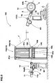
- the tape applying device 1 is incorporated in an apparatus 100 for making a tread assembly for a motorcycle pneumatic tire T, which apparatus 100 comprises: an extruder 11 for extruding raw rubber in a form of tape 3; the tape applying device 1; and a profiled drum 6.
- the above-mentioned rotating object 4 generically means the profiled drum 6 itself and a material previously wound around the drum 6.
- the motorcycle tire T comprises: a tread portion Tt; a pair of axially spaced bead portions Tb each with a bead core TC therein; a pair of sidewall portions Ts extending between the tread edges TE and the bead portions Tb; a carcass Tp extending between the bead portions Tb; and a tread reinforcing belt 7 disposed radially outside the carcass Tp in the tread portion Tt.
- the tread portion Tp is curved so that the maximum tire section width lies between the tread edges TE.
- the drum 6 has, as shown in Fig.1, an outer circumferential surface S which is curved to accord with the curve of the inner surface of the tire belt 7, namely, the tread reinforcing cord layer, e.g. band such as jointless spiral band 9, breaker such as cross-ply breaker 11 and the like. Therefore, the outer diameter of the circumferential surface S of the drum 6 becomes maximum at the center of its width, and the diameter decreases continuously from the center towards each edge of the winding surface S.
- the tread reinforcing cord layer e.g. band such as jointless spiral band 9, breaker such as cross-ply breaker 11 and the like. Therefore, the outer diameter of the circumferential surface S of the drum 6 becomes maximum at the center of its width, and the diameter decreases continuously from the center towards each edge of the winding surface S.
- the belt 7 is first applied or wound. Then, a raw rubber tape 3 is overlap wound on the belt 7, whereby the tread rubber TR is formed by the windings of the tape. Thus, a tread assembly of the belt 7 and tread rubber TR is formed on the drum 6.
- the drum 6 in order to remove the tread assembly, the drum 6 has a collapsible structure as well known in the art.
- the drum 6 is rotated by a motor Md controlled by a controller CON.
- the tape applying device 1 includes an endless conveyer belt J to which the raw rubber tape 3 is adhered with utilizing its tackiness.
- the conveyer belt J is supported and guided by rollers R and runs between a tape receiving section 14 provided near the extruder 11 and an applicator section 17 provided near the drum 6.
- the raw rubber tape 3 extruded from the extruder 11 is adhered onto the conveyer belt J.
- the raw rubber tape 3 is separated from the conveyer belt J at the position of the roller R on the most downstream side, and the separated tape 3 transfers to the drum. Between these sections 14 and 17, an accumulator section 15 is formed.
- the tape receiving section 14 comprises a transfer roller Ra and a cylinder actuator 18.
- the cylinder actuator 18 is controlled by the controller CON in order to move the transfer roller Ra between two positions: a separate position at a small distance from a lower calender roller 11a of the rubber extruder 11; and a contact position at which the transfer roller Ra can contact with the lower calender roller 11a.
- the accumulator section 15 comprises: a going-belt accumulator 15A for the conveyer belt J going from the extruder 11 to the drum 6; and a retuning-belt accumulator 15B for the conveyer belt J retuning from the drum 6 to the extruder 11.
- Each accumulator 15A, 15B is formed by a festoon of the conveyer belt J as shown in Fig.3.
- the conveyer belt J winds between a series of upper horizontal rollers R1u and a series of lower horizontal rollers R1L.
- the upper horizontal rollers R1u are mounted on a fixed horizontal beam 19A of a support frame 19 in a line, whereas the lower upper horizontal rollers R1L are mounted on a vertically-movable horizontal frame 19C in a line.
- the conveyer belt J winds between a series of upper horizontal rollers R2U and a series of lower upper horizontal rollers R2L.
- the upper horizontal rollers R2U are mounted on a fixed horizontal beam 19B of the support frame 19 in a line, whereas the lower upper horizontal rollers R2L are mounted on a vertically-movable horizontal frame 19D in a line.
- the tape applying device 1 includes: a first motor M1 to drive the retuning conveyer belt J in sync with the extrusion speed of the tape which is continuously extruded from the extruder 11; and a second motor M2 to drive the going conveyer belt J intermittently, engaging with the intermittent rotation of the drum 6.
- the first motor M1 and second motor M2 are controlled by the controller CON.
- the conveyer belt J is took out from the retuning-belt accumulator 15B, and the extruded rubber tape 3 is adhered thereto. Then, the conveyer belt J with the rubber tape thereon travels into the going-belt accumulator 15A.
- the conveyer belt J with the rubber tape 3 thereon is accumulated in the going-belt accumulator 15A, and the conveyer belt J on which the tape is to be adhered is took out from the retuning-belt accumulator 15B.
- the applicator section 17 comprises:
- the traverser 21 comprises: lateral guide rails 21A laying in the X-axis direction; and a main carriage 21B on the lateral guide rails 21A.
- the main carriage 21B is movable in the X-axis direction by a driving mechanism engaged with a motor Mx, utilizing for example a ball screw, gears, power transmission belt and the like.
- a driving mechanism engaged with a motor Mx, utilizing for example a ball screw, gears, power transmission belt and the like.
- the let-off roller 16 can traverse the entire width of the drum 6.
- the moving speed, moving distance and moving direction of the main carriage 21B can be completely controlled by controlling the rotation of the motor Mx with the controller CON.
- the radial shifter 22 comprises: radial guide rails 22A laying in the Y-axis direction and fixed to the main carriage 21B; and a sub carriage 22B on the radial guide rails 22A.
- the sub carriage 22B is movable in the Y-axis direction by a similar driving mechanism engaged with a motor My, utilizing for example a ball screw, gears, power transmission belt and the like. By moving the sub carriage 22B forwards, the let-off roller 16 approaches the drum 6.
- the moving speed, moving distance and moving direction of the sub carriage 22B relative to the main carriage 21B can be completely controlled by controlling the rotation of the motor My with the controller CON.
- the tilter 23 comprises: a support shaft 23A extending uprightly from the sub carriage 22B; and a turning bed 23B supported by the support shaft 23A turnably around the axis 23i of the shaft 23A.
- the axis 23i of the support shaft 23A defines the above-mentioned reference axis zi.
- the turning bed 23B is engaged with a motor Mz through a transmission (not shown).
- the turning speed, turning angle and turning direction of the turning bed 23B can be completely controlled by controlling the rotation of the motor Mz with the controller CON.
- the turning angle is detected by an angle sensor such as an encoder or the like and based on the output of the sensor the turning angle is determined by the controller CON.
- a table-like frame 26 is disposed thereon, and a tape guide 25 is arranged on the frame 26 so as to position at almost same height as the rotational axis the drum.
- the tape guide 25 in this example comprises: a platy support arm 27 fixed to the top of the table-like frame 26; and a plurality of rollers R horizontally mounted on the support arm 27.
- the rollers R include: the above-mentioned let-off roller 16 disposed at the front end of the support arm 27; and a large-diameter driving roller 28 for driving the conveyer belt J coupled with the above-mentioned second motor M2.
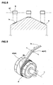
- the rotational axis 16i of the let-off roller 16 is positioned within a standard plane 29 which is a plane 4S perpendicular to the Z-axis direction and including the rotational axis (i) of the drum 6.
- the plane 4S standard plane 29 which includes both of the axis 16i and the axis (i) is perpendicular to the Z-axis direction.
- the notational axis 16i of the let-off roller 16 can move in both of the x-axis direction (traverse direction) and the Y-axis direction (back-and-forth direction towards the rotational axis of the drum), and also can turn around the reference axis zi, as shown in Fig.4.
- the controller CON can control the motions of the traverser 21, radial shifter 22 and tilter 23 so that the rotational axis 16i of the let-off roller 16 becomes substantially parallel with the profile line of the winding surface S which appears in the standard plane 29, while moving in the x-axis and Y-axis directions.
- the reference axis zi passes through the bisecting point P of the width of the let-off roller 16, more specifically, the bisecting point P of the length of the rotational axis 16i of the let-off roller 16. If the reference axis zi does not pass through the bisecting point P, as shown in Fig.5, errors delta x and delta y of the point P in the x-axis direction and Y-axis direction vary according to the turning angle, and thus it becomes necessary to compute and control the feeding speed of the tape, taking account of the variable errors as the traverser 21 and radial shifter 22 move in the x-axis and Y-axis directions.
- the let-off roller 16 is wider than the conveyer belt J, and the conveyer belt J is wider than the rubber tape.
- the diameter of the let-off roller 16 is considerably small when compared with the diameter of the drum.
- the diameter of the let-off roller 16 is less than 20 % of the drum diameter.
- the distance L between the winding surface S and the surface of the conveyer belt J on the let-off roller 16 is not more than 20 mm, preferably not more than 15 mm, more preferably not more than 10 mm, but not less than 3 mm, preferably not less than 5 mm, more preferably not less than 7 mm. If the distance L is more than 20 mm, it becomes difficult to control the overlapping width exactly. If the distance L is less than 3.0 mm, disorder such as constriction is liable to occur at the winding start end of the rubber tape 3.
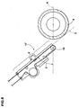
- the going conveyer belt J runs for a certain distance at a constant angle theta with respect to a reference plane K, wherein the reference plane K is a plane including the axis 16i of the let-off roller 16 and the rotational axis (i) of the object 4.
- the reference plane K is a straight line drawn between the axis 16i and axis (i) as shown in Fig.3.
- this straight part F By providing this straight part F, the residual stress and strain of the rubber tape can be reduced during running this part F. To derive this effect, it is preferable that the length of this straight part F is about 60 to 100 cm.
- the angle theta is preferably not less than 20 degrees, more preferably not less than 30 degrees, but not more than 70 degrees, preferably not more than 60 degrees, more preferably not more than 50 degrees. It is most preferable that the extension T of the straight part F is tangent to the winding surface S and the rubber tape 3 runs along this line, as shown in Fig.6.
- a tape cutter 31 is disposed in this straight part F.
- the tape cutter 31 has a rotary blade of which rotation by a motor Mc is controlled by the controller CON so as to be able to cut the rubber tape on the moving conveyer belt J.
- the applicator section 17 comprises a presser roller 40, at least the surface of which is formed by a spongy material which can make elastic deformation easily.
- the presser roller 40 is rotatably horizontally supported by a holder attached to the end of the rod of a cylinder actuator 41 mounted on the support arm 27.
- the presser roller 40 can press the rubber tape 3 against the winding surface s.
- the presser roller 40 is used at least at one point when the winding start end of the rubber tape 3 is adhered to the winding surface S. Also, it is possible to use it all the time during winding in order to press the rubber tape 3 against the winding surface S.
- This cylinder actuator 41 is also controlled by the controller CON.
- the above-mentioned controller CON is a computer which comprises a central processing unit, memory, input and output devices (such as keyboard, display, printer) and the like as well known in the art.
- the driving units of the above-mentioned motors Md, M1, M2, Mx, My, Mz, Mc and actuators 18, 41 are connected to the computer through interface adapters.
- various sensors for detecting the turning angle and position of the let-off roller 16, and sensors for the rubber tape at various positions and the like are also connected to the computer through interface adapters.
- the controller CON can operate the tape applying device 1 according to the program stored in the memory and the outputs of the sensors.
- a rubber tape 3 was wound on a belt previously wound on the drum.
- the width of the winding surface of the drum was 185 mm.
- the difference (Dc-Ds) between the diameter Dc of the winding surface at the center and the diameter Ds at the edges was 120 mm.
Applications Claiming Priority (1)
| Application Number | Priority Date | Filing Date | Title |
|---|---|---|---|
| JP2005330491A JP4398936B2 (ja) | 2005-11-15 | 2005-11-15 | ゴムストリップの貼付装置 |
Publications (2)
| Publication Number | Publication Date |
|---|---|
| EP1785263A1 true EP1785263A1 (fr) | 2007-05-16 |
| EP1785263B1 EP1785263B1 (fr) | 2009-03-11 |
Family
ID=37685716
Family Applications (1)
| Application Number | Title | Priority Date | Filing Date |
|---|---|---|---|
| EP06022748A Expired - Fee Related EP1785263B1 (fr) | 2005-11-15 | 2006-10-31 | Dispositif pour appliquer une bande caoutchoutée |
Country Status (5)
| Country | Link |
|---|---|
| US (1) | US20070107848A1 (fr) |
| EP (1) | EP1785263B1 (fr) |
| JP (1) | JP4398936B2 (fr) |
| CN (1) | CN1966252B (fr) |
| DE (1) | DE602006005577D1 (fr) |
Cited By (6)
| Publication number | Priority date | Publication date | Assignee | Title |
|---|---|---|---|---|
| EP2116362A1 (fr) * | 2008-05-05 | 2009-11-11 | Tianjin Saixiang Technology Co., Ltd. | Système d'enroulement de bande tridimensionnel pour bandage OTR radial tout acier, géant et spécifique |
| WO2012032252A1 (fr) * | 2010-09-10 | 2012-03-15 | Societe De Technologie Michelin | Procede de fabrication d'une ebauche crue de pneumatique mettant en oeuvre une etape de rouletage |
| WO2013093765A1 (fr) | 2011-12-22 | 2013-06-27 | Pirelli Tyre S.P.A. | Procédé et appareil pour fabriquer des pneumatiques pour roues de véhicule |
| WO2016058572A1 (fr) * | 2014-10-14 | 2016-04-21 | Harburg-Freudenberger Maschinenbau Gmbh | Dispositif et procédé de production de pneus crus |
| CN114734623A (zh) * | 2022-03-31 | 2022-07-12 | 速博达(深圳)自动化有限公司 | 贴包胶装置 |
| EP4194190A4 (fr) * | 2020-08-07 | 2024-02-14 | Bridgestone Corp | Dispositif de production de pneumatique et procédé de production de pneumatique |
Families Citing this family (18)
| Publication number | Priority date | Publication date | Assignee | Title |
|---|---|---|---|---|
| JP2011152664A (ja) * | 2010-01-26 | 2011-08-11 | Toyo Tire & Rubber Co Ltd | タイヤ成型装置 |
| JP4922425B2 (ja) * | 2010-03-19 | 2012-04-25 | 住友ゴム工業株式会社 | ゴムストリップの押付け装置 |
| JP5619456B2 (ja) * | 2010-03-30 | 2014-11-05 | 株式会社ブリヂストン | タイヤの製造方法、タイヤの製造装置、及びタイヤ |
| JP5671403B2 (ja) * | 2011-04-25 | 2015-02-18 | 住友ゴム工業株式会社 | ゴムストリップの貼付装置 |
| JP5832188B2 (ja) * | 2011-07-22 | 2015-12-16 | 住友ゴム工業株式会社 | ゴムストリップの貼り付け方法 |
| CN104768739B (zh) | 2012-10-09 | 2017-09-29 | 倍耐力轮胎股份公司 | 用于在构建轮胎的处理中控制由弹性体材料制造的连续细长元件的厚度的方法 |
| JP5767623B2 (ja) * | 2012-12-27 | 2015-08-19 | 住友ゴム工業株式会社 | ゴムストリップの貼付装置 |
| JP6121218B2 (ja) * | 2013-04-03 | 2017-04-26 | 住友ゴム工業株式会社 | 生タイヤの成形装置および生タイヤの成形方法 |
| NL2011764C2 (en) * | 2013-11-08 | 2015-05-11 | Vmi Holland Bv | Method for centering a tire component. |
| JP6280374B2 (ja) * | 2014-01-23 | 2018-02-14 | 住友ゴム工業株式会社 | ゴムストリップの押付け装置 |
| JP5945290B2 (ja) * | 2014-02-24 | 2016-07-05 | 住友ゴム工業株式会社 | タイヤ部材形成装置 |
| NL2014195B1 (en) * | 2015-01-27 | 2017-01-11 | Vmi Holland Bv | Validation tool and method for validating optical equipment. |
| CN106394989B (zh) * | 2016-11-21 | 2019-08-23 | 英华达(上海)科技有限公司 | 贴膜装置以及贴膜方法 |
| CN107813487B (zh) * | 2017-12-05 | 2023-04-07 | 安徽伊士达耐腐设备股份有限公司 | 容器器壁加工装置 |
| CN109263108A (zh) * | 2018-10-30 | 2019-01-25 | 软控股份有限公司 | 供料装置 |
| CN109333981A (zh) * | 2018-11-15 | 2019-02-15 | 联亚智能科技(苏州)有限公司 | 一种胶条输送装置以及橡胶部件缠绕生产线 |
| CN111251590B (zh) * | 2020-01-17 | 2021-04-20 | 大连理工大学 | 一种固体火箭发动机绝热层自动化缠绕设备及其使用方法 |
| CN114043712A (zh) * | 2021-10-15 | 2022-02-15 | 镇江奥立特机械制造有限公司 | 一种多级智能柔性碳纤维制造传动设备 |
Citations (7)
| Publication number | Priority date | Publication date | Assignee | Title |
|---|---|---|---|---|
| JPS5959432A (ja) * | 1982-09-30 | 1984-04-05 | Yokohama Rubber Co Ltd:The | タイヤ成形工程におけるフイルム状材料とサイドウオ−ル構成部材の同時貼り方法 |
| LU87565A1 (fr) * | 1988-07-28 | 1989-10-26 | Goodyear Tire & Rubber | Procede et appareil d'application de spires pour fabrication d'une bande de roulement |
| EP0542431A1 (fr) * | 1991-11-13 | 1993-05-19 | Bridgestone Corporation | Dispositif pour enrouler une couche en forme de bande |
| DE4314114A1 (de) * | 1993-04-29 | 1994-11-03 | Krupp Maschinentechnik | Verfahren zum Auflegen eines gummierten Textilgewebestreifens auf eine Reifenaufbautrommel und Vorrichtung für die Durchführung des Verfahrens |
| JP2000326419A (ja) * | 1999-05-20 | 2000-11-28 | Sumitomo Rubber Ind Ltd | タイヤ構成帯状ゴム部材貼付装置 |
| JP2003326611A (ja) * | 2002-05-14 | 2003-11-19 | Sumitomo Rubber Ind Ltd | ゴムストリップ貼付成形装置 |
| WO2005009726A2 (fr) * | 2003-07-28 | 2005-02-03 | Vmi Epe Holland B.V. | Appareil de pose d'une bande de roulement |
Family Cites Families (3)
| Publication number | Priority date | Publication date | Assignee | Title |
|---|---|---|---|---|
| US4240863A (en) * | 1979-04-12 | 1980-12-23 | Caterpillar Tractor Co. | Control system for an elastomer extrusion and applicator apparatus |
| JP3322648B2 (ja) * | 1999-03-03 | 2002-09-09 | 住友ゴム工業株式会社 | ゴム搬送装置およびそれを用いたゴム成形装置 |
| DE602005004581T2 (de) * | 2004-10-14 | 2009-01-29 | Sumitomo Rubber Industries Ltd., Kobe | Verfahren und Vorrichtung zur Herstellung eines Gegenstandes durch Wickeln eines Gummistreifens auf einen Tragkörper |
-
2005
- 2005-11-15 JP JP2005330491A patent/JP4398936B2/ja not_active Expired - Fee Related
-
2006
- 2006-10-31 DE DE602006005577T patent/DE602006005577D1/de active Active
- 2006-10-31 EP EP06022748A patent/EP1785263B1/fr not_active Expired - Fee Related
- 2006-11-06 US US11/593,113 patent/US20070107848A1/en not_active Abandoned
- 2006-11-14 CN CN2006101457325A patent/CN1966252B/zh not_active Expired - Fee Related
Patent Citations (7)
| Publication number | Priority date | Publication date | Assignee | Title |
|---|---|---|---|---|
| JPS5959432A (ja) * | 1982-09-30 | 1984-04-05 | Yokohama Rubber Co Ltd:The | タイヤ成形工程におけるフイルム状材料とサイドウオ−ル構成部材の同時貼り方法 |
| LU87565A1 (fr) * | 1988-07-28 | 1989-10-26 | Goodyear Tire & Rubber | Procede et appareil d'application de spires pour fabrication d'une bande de roulement |
| EP0542431A1 (fr) * | 1991-11-13 | 1993-05-19 | Bridgestone Corporation | Dispositif pour enrouler une couche en forme de bande |
| DE4314114A1 (de) * | 1993-04-29 | 1994-11-03 | Krupp Maschinentechnik | Verfahren zum Auflegen eines gummierten Textilgewebestreifens auf eine Reifenaufbautrommel und Vorrichtung für die Durchführung des Verfahrens |
| JP2000326419A (ja) * | 1999-05-20 | 2000-11-28 | Sumitomo Rubber Ind Ltd | タイヤ構成帯状ゴム部材貼付装置 |
| JP2003326611A (ja) * | 2002-05-14 | 2003-11-19 | Sumitomo Rubber Ind Ltd | ゴムストリップ貼付成形装置 |
| WO2005009726A2 (fr) * | 2003-07-28 | 2005-02-03 | Vmi Epe Holland B.V. | Appareil de pose d'une bande de roulement |
Cited By (8)
| Publication number | Priority date | Publication date | Assignee | Title |
|---|---|---|---|---|
| EP2116362A1 (fr) * | 2008-05-05 | 2009-11-11 | Tianjin Saixiang Technology Co., Ltd. | Système d'enroulement de bande tridimensionnel pour bandage OTR radial tout acier, géant et spécifique |
| WO2012032252A1 (fr) * | 2010-09-10 | 2012-03-15 | Societe De Technologie Michelin | Procede de fabrication d'une ebauche crue de pneumatique mettant en oeuvre une etape de rouletage |
| FR2964594A1 (fr) * | 2010-09-10 | 2012-03-16 | Michelin Soc Tech | Procede de fabrication d'une ebauche crue de pneumatique mettant en œuvre une etape de rouletage |
| WO2013093765A1 (fr) | 2011-12-22 | 2013-06-27 | Pirelli Tyre S.P.A. | Procédé et appareil pour fabriquer des pneumatiques pour roues de véhicule |
| WO2016058572A1 (fr) * | 2014-10-14 | 2016-04-21 | Harburg-Freudenberger Maschinenbau Gmbh | Dispositif et procédé de production de pneus crus |
| US10967592B2 (en) | 2014-10-14 | 2021-04-06 | Harburg-Freudenberger Maschinenbau Gmbh | Device and method for producing green tyres |
| EP4194190A4 (fr) * | 2020-08-07 | 2024-02-14 | Bridgestone Corp | Dispositif de production de pneumatique et procédé de production de pneumatique |
| CN114734623A (zh) * | 2022-03-31 | 2022-07-12 | 速博达(深圳)自动化有限公司 | 贴包胶装置 |
Also Published As
| Publication number | Publication date |
|---|---|
| JP4398936B2 (ja) | 2010-01-13 |
| CN1966252A (zh) | 2007-05-23 |
| JP2007136740A (ja) | 2007-06-07 |
| US20070107848A1 (en) | 2007-05-17 |
| EP1785263B1 (fr) | 2009-03-11 |
| DE602006005577D1 (de) | 2009-04-23 |
| CN1966252B (zh) | 2012-08-29 |
Similar Documents
| Publication | Publication Date | Title |
|---|---|---|
| EP1785263B1 (fr) | Dispositif pour appliquer une bande caoutchoutée | |
| US7510616B2 (en) | Producing method of rubber strip winding body, and rubber strip winding apparatus | |
| KR100909339B1 (ko) | 타이어용 고무 스트립 와인딩 장치 | |
| EP2199071A1 (fr) | Procédé et appareil pour la fabrication d'un pneu non vulcanisé | |
| EP2347893B1 (fr) | Dispositif de fabrication de pneu et procédé de fabrication de pneu | |
| JP5297711B2 (ja) | ゴム部材の成形装置及び成形方法 | |
| US10307980B2 (en) | Tire building applicator members and systems | |
| EP0264720B1 (fr) | Dispositif d'alimentation pour bandes | |
| EP2116362B1 (fr) | Système d'enroulement tridimensionnel d'une bande pour bandage OTR radial tout acier, géant et spécifique. | |
| EP0268544B1 (fr) | Appareil pour déposer une bande continue en matière élastomère sur une surface | |
| CN102019703A (zh) | 轮胎成型机的带束层自动定中装置 | |
| JP2008307749A (ja) | 更生タイヤの製造方法及び製造装置 | |
| CN107962768B (zh) | 自动控制覆胶质量的缠绕覆面机操作系统及方法 | |
| JPS6137422A (ja) | タイヤ再生装置 | |
| MX2010011039A (es) | Metodo y aparato para producir neumaticos verdes. | |
| US10328652B2 (en) | Strip-winding method and strip-winding apparatus | |
| JP4673614B2 (ja) | タイヤ用ゴム部材の製造方法 | |
| JP5220630B2 (ja) | 加硫タイヤの製造方法および製造装置 | |
| KR101769678B1 (ko) | 연속동작으로 센터링이 가능한 타이어 반제품 와인딩 장치 | |
| CN220614087U (zh) | 一种轮胎帘布预处理装置 | |
| JP2002137278A (ja) | 押出・成形方法及びその装置 | |
| JP4988512B2 (ja) | タイヤ構成部材供給装置 | |
| JP2010240961A (ja) | タイヤ用インナーライナー層の成形装置 | |
| USRE28043E (en) | Method of building a tire casing from a strip op rubber | |
| CN109049775B (zh) | 一种传送带的生产方法 |
Legal Events
| Date | Code | Title | Description |
|---|---|---|---|
| PUAI | Public reference made under article 153(3) epc to a published international application that has entered the european phase |
Free format text: ORIGINAL CODE: 0009012 |
|
| AK | Designated contracting states |
Kind code of ref document: A1 Designated state(s): AT BE BG CH CY CZ DE DK EE ES FI FR GB GR HU IE IS IT LI LT LU LV MC NL PL PT RO SE SI SK TR |
|
| AX | Request for extension of the european patent |
Extension state: AL BA HR MK YU |
|
| 17P | Request for examination filed |
Effective date: 20071106 |
|
| 17Q | First examination report despatched |
Effective date: 20071213 |
|
| AKX | Designation fees paid |
Designated state(s): DE FR |
|
| R17C | First examination report despatched (corrected) |
Effective date: 20071220 |
|
| GRAP | Despatch of communication of intention to grant a patent |
Free format text: ORIGINAL CODE: EPIDOSNIGR1 |
|
| GRAS | Grant fee paid |
Free format text: ORIGINAL CODE: EPIDOSNIGR3 |
|
| GRAA | (expected) grant |
Free format text: ORIGINAL CODE: 0009210 |
|
| AK | Designated contracting states |
Kind code of ref document: B1 Designated state(s): DE FR |
|
| REF | Corresponds to: |
Ref document number: 602006005577 Country of ref document: DE Date of ref document: 20090423 Kind code of ref document: P |
|
| PLBE | No opposition filed within time limit |
Free format text: ORIGINAL CODE: 0009261 |
|
| STAA | Information on the status of an ep patent application or granted ep patent |
Free format text: STATUS: NO OPPOSITION FILED WITHIN TIME LIMIT |
|
| 26N | No opposition filed |
Effective date: 20091214 |
|
| PGFP | Annual fee paid to national office [announced via postgrant information from national office to epo] |
Ref country code: FR Payment date: 20131009 Year of fee payment: 8 Ref country code: DE Payment date: 20131023 Year of fee payment: 8 |
|
| REG | Reference to a national code |
Ref country code: DE Ref legal event code: R119 Ref document number: 602006005577 Country of ref document: DE |
|
| PG25 | Lapsed in a contracting state [announced via postgrant information from national office to epo] |
Ref country code: DE Free format text: LAPSE BECAUSE OF NON-PAYMENT OF DUE FEES Effective date: 20150501 |
|
| REG | Reference to a national code |
Ref country code: FR Ref legal event code: ST Effective date: 20150630 |
|
| PG25 | Lapsed in a contracting state [announced via postgrant information from national office to epo] |
Ref country code: FR Free format text: LAPSE BECAUSE OF NON-PAYMENT OF DUE FEES Effective date: 20141031 |