EP1784633B1 - Verfahren zur analyse einer probe und vorrichtung dafür - Google Patents
Verfahren zur analyse einer probe und vorrichtung dafür Download PDFInfo
- Publication number
- EP1784633B1 EP1784633B1 EP05768147A EP05768147A EP1784633B1 EP 1784633 B1 EP1784633 B1 EP 1784633B1 EP 05768147 A EP05768147 A EP 05768147A EP 05768147 A EP05768147 A EP 05768147A EP 1784633 B1 EP1784633 B1 EP 1784633B1
- Authority
- EP
- European Patent Office
- Prior art keywords
- sample
- modification
- labels
- processing means
- light beam
- Prior art date
- Legal status (The legal status is an assumption and is not a legal conclusion. Google has not performed a legal analysis and makes no representation as to the accuracy of the status listed.)
- Active
Links
- 238000000034 method Methods 0.000 title claims abstract description 63
- 238000012986 modification Methods 0.000 claims abstract description 66
- 230000004048 modification Effects 0.000 claims abstract description 54
- 230000001678 irradiating effect Effects 0.000 claims abstract description 12
- 230000003213 activating effect Effects 0.000 claims description 42
- 238000012545 processing Methods 0.000 claims description 31
- 230000005284 excitation Effects 0.000 claims description 23
- 238000004458 analytical method Methods 0.000 claims description 17
- 230000004044 response Effects 0.000 claims description 17
- 238000001514 detection method Methods 0.000 claims description 13
- 230000005855 radiation Effects 0.000 claims description 10
- 230000003287 optical effect Effects 0.000 claims description 9
- 108090000623 proteins and genes Proteins 0.000 claims description 9
- 230000033001 locomotion Effects 0.000 claims description 8
- 239000000463 material Substances 0.000 claims description 7
- 238000012546 transfer Methods 0.000 claims description 6
- 239000012620 biological material Substances 0.000 claims description 5
- 230000022131 cell cycle Effects 0.000 claims description 5
- 230000030833 cell death Effects 0.000 claims description 5
- 230000001419 dependent effect Effects 0.000 claims description 5
- 230000028023 exocytosis Effects 0.000 claims description 5
- 230000009545 invasion Effects 0.000 claims description 5
- 230000003612 virological effect Effects 0.000 claims description 5
- 230000012202 endocytosis Effects 0.000 claims description 4
- 239000012528 membrane Substances 0.000 claims description 3
- 238000013500 data storage Methods 0.000 claims description 2
- 239000000523 sample Substances 0.000 abstract description 139
- 238000002474 experimental method Methods 0.000 abstract description 15
- 239000012472 biological sample Substances 0.000 abstract description 2
- 230000001143 conditioned effect Effects 0.000 abstract 1
- 230000008569 process Effects 0.000 description 29
- 210000004027 cell Anatomy 0.000 description 28
- 230000004913 activation Effects 0.000 description 20
- 238000004061 bleaching Methods 0.000 description 16
- 230000008859 change Effects 0.000 description 14
- 239000007844 bleaching agent Substances 0.000 description 11
- 230000007613 environmental effect Effects 0.000 description 9
- 238000002376 fluorescence recovery after photobleaching Methods 0.000 description 9
- 238000003384 imaging method Methods 0.000 description 9
- 230000007246 mechanism Effects 0.000 description 9
- 238000009792 diffusion process Methods 0.000 description 7
- 239000007850 fluorescent dye Substances 0.000 description 7
- 238000005286 illumination Methods 0.000 description 6
- 238000010586 diagram Methods 0.000 description 5
- 238000000695 excitation spectrum Methods 0.000 description 5
- 239000007789 gas Substances 0.000 description 5
- 239000007788 liquid Substances 0.000 description 5
- 230000009471 action Effects 0.000 description 4
- 210000000170 cell membrane Anatomy 0.000 description 4
- 238000005259 measurement Methods 0.000 description 4
- 238000000386 microscopy Methods 0.000 description 4
- 239000002245 particle Substances 0.000 description 4
- 102000004169 proteins and genes Human genes 0.000 description 4
- 238000011084 recovery Methods 0.000 description 4
- 102000004190 Enzymes Human genes 0.000 description 3
- 108090000790 Enzymes Proteins 0.000 description 3
- 108010043121 Green Fluorescent Proteins Proteins 0.000 description 3
- 102000004144 Green Fluorescent Proteins Human genes 0.000 description 3
- 238000013459 approach Methods 0.000 description 3
- 230000001413 cellular effect Effects 0.000 description 3
- 238000000295 emission spectrum Methods 0.000 description 3
- 238000002866 fluorescence resonance energy transfer Methods 0.000 description 3
- 239000005090 green fluorescent protein Substances 0.000 description 3
- 238000010191 image analysis Methods 0.000 description 3
- 230000002452 interceptive effect Effects 0.000 description 3
- 239000000203 mixture Substances 0.000 description 3
- 241000243290 Aequorea Species 0.000 description 2
- 206010036618 Premenstrual syndrome Diseases 0.000 description 2
- QVGXLLKOCUKJST-UHFFFAOYSA-N atomic oxygen Chemical compound [O] QVGXLLKOCUKJST-UHFFFAOYSA-N 0.000 description 2
- 230000015572 biosynthetic process Effects 0.000 description 2
- 238000004113 cell culture Methods 0.000 description 2
- 210000002421 cell wall Anatomy 0.000 description 2
- 239000003795 chemical substances by application Substances 0.000 description 2
- 150000001875 compounds Chemical class 0.000 description 2
- 238000010226 confocal imaging Methods 0.000 description 2
- 230000000694 effects Effects 0.000 description 2
- 230000005670 electromagnetic radiation Effects 0.000 description 2
- 238000000799 fluorescence microscopy Methods 0.000 description 2
- 238000011835 investigation Methods 0.000 description 2
- 230000007774 longterm Effects 0.000 description 2
- 230000035772 mutation Effects 0.000 description 2
- 210000003463 organelle Anatomy 0.000 description 2
- 239000001301 oxygen Substances 0.000 description 2
- 229910052760 oxygen Inorganic materials 0.000 description 2
- 241000894007 species Species 0.000 description 2
- 239000000126 substance Substances 0.000 description 2
- 210000001519 tissue Anatomy 0.000 description 2
- 230000032258 transport Effects 0.000 description 2
- 230000007723 transport mechanism Effects 0.000 description 2
- 241000251468 Actinopterygii Species 0.000 description 1
- 241000242757 Anthozoa Species 0.000 description 1
- OYPRJOBELJOOCE-UHFFFAOYSA-N Calcium Chemical compound [Ca] OYPRJOBELJOOCE-UHFFFAOYSA-N 0.000 description 1
- 235000014653 Carica parviflora Nutrition 0.000 description 1
- MYMOFIZGZYHOMD-UHFFFAOYSA-N Dioxygen Chemical compound O=O MYMOFIZGZYHOMD-UHFFFAOYSA-N 0.000 description 1
- 241000233866 Fungi Species 0.000 description 1
- 101001023784 Heteractis crispa GFP-like non-fluorescent chromoprotein Proteins 0.000 description 1
- 241000238631 Hexapoda Species 0.000 description 1
- 241000124008 Mammalia Species 0.000 description 1
- 241001465754 Metazoa Species 0.000 description 1
- 241000242583 Scyphozoa Species 0.000 description 1
- 230000002159 abnormal effect Effects 0.000 description 1
- 230000009286 beneficial effect Effects 0.000 description 1
- 230000033228 biological regulation Effects 0.000 description 1
- 210000004204 blood vessel Anatomy 0.000 description 1
- 229910052791 calcium Inorganic materials 0.000 description 1
- 239000011575 calcium Substances 0.000 description 1
- 150000001720 carbohydrates Chemical class 0.000 description 1
- 235000014633 carbohydrates Nutrition 0.000 description 1
- 230000015556 catabolic process Effects 0.000 description 1
- 230000032823 cell division Effects 0.000 description 1
- 230000033077 cellular process Effects 0.000 description 1
- 230000001186 cumulative effect Effects 0.000 description 1
- 210000004292 cytoskeleton Anatomy 0.000 description 1
- 238000011161 development Methods 0.000 description 1
- 230000018109 developmental process Effects 0.000 description 1
- 201000010099 disease Diseases 0.000 description 1
- 208000037265 diseases, disorders, signs and symptoms Diseases 0.000 description 1
- 238000002224 dissection Methods 0.000 description 1
- 239000003814 drug Substances 0.000 description 1
- 229940000406 drug candidate Drugs 0.000 description 1
- 238000011156 evaluation Methods 0.000 description 1
- 238000002284 excitation--emission spectrum Methods 0.000 description 1
- 230000001747 exhibiting effect Effects 0.000 description 1
- 238000001914 filtration Methods 0.000 description 1
- 108010021843 fluorescent protein 583 Proteins 0.000 description 1
- 108091006047 fluorescent proteins Proteins 0.000 description 1
- 102000034287 fluorescent proteins Human genes 0.000 description 1
- 238000002347 injection Methods 0.000 description 1
- 239000007924 injection Substances 0.000 description 1
- 230000003993 interaction Effects 0.000 description 1
- 230000005865 ionizing radiation Effects 0.000 description 1
- 150000002500 ions Chemical class 0.000 description 1
- 238000002955 isolation Methods 0.000 description 1
- 238000012804 iterative process Methods 0.000 description 1
- 230000001535 kindling effect Effects 0.000 description 1
- 238000000608 laser ablation Methods 0.000 description 1
- 230000004807 localization Effects 0.000 description 1
- 210000001161 mammalian embryo Anatomy 0.000 description 1
- 238000000520 microinjection Methods 0.000 description 1
- 230000009149 molecular binding Effects 0.000 description 1
- 239000002547 new drug Substances 0.000 description 1
- BOPGDPNILDQYTO-NNYOXOHSSA-N nicotinamide-adenine dinucleotide Chemical compound C1=CCC(C(=O)N)=CN1[C@H]1[C@H](O)[C@H](O)[C@@H](COP(O)(=O)OP(O)(=O)OC[C@@H]2[C@H]([C@@H](O)[C@@H](O2)N2C3=NC=NC(N)=C3N=C2)O)O1 BOPGDPNILDQYTO-NNYOXOHSSA-N 0.000 description 1
- 229930027945 nicotinamide-adenine dinucleotide Natural products 0.000 description 1
- 238000012576 optical tweezer Methods 0.000 description 1
- 210000000056 organ Anatomy 0.000 description 1
- 230000008212 organismal development Effects 0.000 description 1
- 230000008520 organization Effects 0.000 description 1
- 230000002186 photoactivation Effects 0.000 description 1
- 230000002035 prolonged effect Effects 0.000 description 1
- 238000010791 quenching Methods 0.000 description 1
- 238000004064 recycling Methods 0.000 description 1
- 210000001525 retina Anatomy 0.000 description 1
- PYWVYCXTNDRMGF-UHFFFAOYSA-N rhodamine B Chemical compound [Cl-].C=12C=CC(=[N+](CC)CC)C=C2OC2=CC(N(CC)CC)=CC=C2C=1C1=CC=CC=C1C(O)=O PYWVYCXTNDRMGF-UHFFFAOYSA-N 0.000 description 1
- 238000005070 sampling Methods 0.000 description 1
- 229910052594 sapphire Inorganic materials 0.000 description 1
- 239000010980 sapphire Substances 0.000 description 1
- 210000000130 stem cell Anatomy 0.000 description 1
- 239000000758 substrate Substances 0.000 description 1
- 238000003786 synthesis reaction Methods 0.000 description 1
- 230000002123 temporal effect Effects 0.000 description 1
- 238000001890 transfection Methods 0.000 description 1
- 230000007704 transition Effects 0.000 description 1
- 238000012800 visualization Methods 0.000 description 1
Images


Classifications
-
- G—PHYSICS
- G01—MEASURING; TESTING
- G01N—INVESTIGATING OR ANALYSING MATERIALS BY DETERMINING THEIR CHEMICAL OR PHYSICAL PROPERTIES
- G01N21/00—Investigating or analysing materials by the use of optical means, i.e. using sub-millimetre waves, infrared, visible or ultraviolet light
- G01N21/62—Systems in which the material investigated is excited whereby it emits light or causes a change in wavelength of the incident light
- G01N21/63—Systems in which the material investigated is excited whereby it emits light or causes a change in wavelength of the incident light optically excited
- G01N21/64—Fluorescence; Phosphorescence
- G01N21/645—Specially adapted constructive features of fluorimeters
- G01N21/6456—Spatial resolved fluorescence measurements; Imaging
- G01N21/6458—Fluorescence microscopy
-
- G—PHYSICS
- G01—MEASURING; TESTING
- G01N—INVESTIGATING OR ANALYSING MATERIALS BY DETERMINING THEIR CHEMICAL OR PHYSICAL PROPERTIES
- G01N21/00—Investigating or analysing materials by the use of optical means, i.e. using sub-millimetre waves, infrared, visible or ultraviolet light
- G01N21/62—Systems in which the material investigated is excited whereby it emits light or causes a change in wavelength of the incident light
- G01N21/63—Systems in which the material investigated is excited whereby it emits light or causes a change in wavelength of the incident light optically excited
- G01N21/64—Fluorescence; Phosphorescence
- G01N21/6428—Measuring fluorescence of fluorescent products of reactions or of fluorochrome labelled reactive substances, e.g. measuring quenching effects, using measuring "optrodes"
-
- G—PHYSICS
- G01—MEASURING; TESTING
- G01N—INVESTIGATING OR ANALYSING MATERIALS BY DETERMINING THEIR CHEMICAL OR PHYSICAL PROPERTIES
- G01N21/00—Investigating or analysing materials by the use of optical means, i.e. using sub-millimetre waves, infrared, visible or ultraviolet light
- G01N21/62—Systems in which the material investigated is excited whereby it emits light or causes a change in wavelength of the incident light
- G01N21/63—Systems in which the material investigated is excited whereby it emits light or causes a change in wavelength of the incident light optically excited
- G01N21/64—Fluorescence; Phosphorescence
- G01N21/645—Specially adapted constructive features of fluorimeters
-
- G—PHYSICS
- G01—MEASURING; TESTING
- G01N—INVESTIGATING OR ANALYSING MATERIALS BY DETERMINING THEIR CHEMICAL OR PHYSICAL PROPERTIES
- G01N33/00—Investigating or analysing materials by specific methods not covered by groups G01N1/00 - G01N31/00
- G01N33/48—Biological material, e.g. blood, urine; Haemocytometers
- G01N33/50—Chemical analysis of biological material, e.g. blood, urine; Testing involving biospecific ligand binding methods; Immunological testing
- G01N33/5005—Chemical analysis of biological material, e.g. blood, urine; Testing involving biospecific ligand binding methods; Immunological testing involving human or animal cells
-
- G—PHYSICS
- G01—MEASURING; TESTING
- G01N—INVESTIGATING OR ANALYSING MATERIALS BY DETERMINING THEIR CHEMICAL OR PHYSICAL PROPERTIES
- G01N33/00—Investigating or analysing materials by specific methods not covered by groups G01N1/00 - G01N31/00
- G01N33/48—Biological material, e.g. blood, urine; Haemocytometers
- G01N33/50—Chemical analysis of biological material, e.g. blood, urine; Testing involving biospecific ligand binding methods; Immunological testing
- G01N33/58—Chemical analysis of biological material, e.g. blood, urine; Testing involving biospecific ligand binding methods; Immunological testing involving labelled substances
- G01N33/582—Chemical analysis of biological material, e.g. blood, urine; Testing involving biospecific ligand binding methods; Immunological testing involving labelled substances with fluorescent label
-
- G—PHYSICS
- G01—MEASURING; TESTING
- G01N—INVESTIGATING OR ANALYSING MATERIALS BY DETERMINING THEIR CHEMICAL OR PHYSICAL PROPERTIES
- G01N21/00—Investigating or analysing materials by the use of optical means, i.e. using sub-millimetre waves, infrared, visible or ultraviolet light
- G01N21/62—Systems in which the material investigated is excited whereby it emits light or causes a change in wavelength of the incident light
- G01N21/63—Systems in which the material investigated is excited whereby it emits light or causes a change in wavelength of the incident light optically excited
- G01N21/64—Fluorescence; Phosphorescence
- G01N21/6428—Measuring fluorescence of fluorescent products of reactions or of fluorochrome labelled reactive substances, e.g. measuring quenching effects, using measuring "optrodes"
- G01N2021/6432—Quenching
Definitions
- This invention relates to a method and apparatus for analysing samples of biological material. More particularly, it concerns the investigation of processes in samples such as cells, in a way that may not interfere with cell functioning. Such investigation may provide greater understanding of complex processes in life science and medicine, assist the evaluation of new drug candidates, and enable the detection of disease or abnormal processes.
- the complexity of the processes is such that tools are required to isolate specific types of processes which can be studied in isolation, or in combination with a small number of other processes.
- labels in the form of fluorescent molecules in fluorescence microscopy
- a label may be extrinsic (that is, added to a sample) or intrinsic (such as a molecule which is present in the sample that is inherently distinctively coloured or fluorescent).
- a fluorescent molecule has a specific excitation spectrum, being more strongly excited at some wavelengths and less strongly excited at others. It also has a specific emission spectrum, emitting more intensely at some wavelengths, and less intensely at others.
- the excitation and emission spectra may range from the ultraviolet to the infrared.
- fluorescent labels have been developed from chemical molecules, such as Rhodamine and Fluoroscein. Further fluorescent labels have been developed from molecules found in luminescent organisms, for example the Aequorea Jellyfish which has provided the Green Fluorescent Protein (GFP), and various corals providing DsRed and HcRed. These have been termed AFPs (Aequorea Fluorescent Proteins).
- the fluorescent labels may be associated with specific molecules of interest (DNA, RNA, proteins, carbohydrates, antibodies, etc). Alternatively they may be made to be sensitive to certain characteristics (such as ionic concentration, pH, voltage potential, temperature, the presence of a specific enzyme, the presence of specific enzyme substrates, force), altering their fluorescent properties according to these characteristics. These labels may be introduced into cells by passing through the cell membrane or by injection. Alternatively they may be formed internally as part of the normal functioning of the cell, in the case of the genetically encoded labels such as the AFPs.
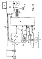
- a microscope 10 is fitted with a light source 12 for illuminating a sample 4b. It may be in the form of a lamp, laser or light emitting diode, for example.
- the microscope is fitted with optical filters 14 so that the light emanating from the sample may be observed at selected wavebands. Examination of the spatial and temporal distribution of light from the sample may provide information on the structure and dynamics of the sample.
- Phase contrast illumination may be employed to enhance imaging of thin samples.
- Polarised light may be used to permit the visualisation of very thin samples with small refractive index changes, for example using differential interference contrast (DIC) techniques.
- DIC differential interference contrast
- the microscope is fitted with an image acquisition system, comprising a light sensitive detector 16 (sensitive from the ultraviolet to the infrared) such as a CCD camera, and recording means such as a video recorder or computer 18 with a memory device 20, so that dynamic behaviour of the sample may be captured and analysed offline. For example, the velocity, distance travelled and path of moving parts of the sample may be monitored.
- a light sensitive detector 16 sensitive from the ultraviolet to the infrared
- recording means such as a video recorder or computer 18 with a memory device 20
- the system may employ a focus drive mechanism for altering the position of the imaging focus plane.
- Various algorithms may be used to establish and maintain the optical focal plane.
- Volumetric (XYZ) and volumetric time series (XYZT) data may be acquired using deconvolution techniques. By selecting suitable excitation wavebands and/or selecting suitable optical filter sets, volumetric multi-wavelength (XYWZ) and volumetric multi-wavelength time series (XYWZT) data may be acquired.
- Operations of the microscope are controlled by a microscope controller 24 in response to commands from processing means in the form of computer 18. Instructions may be entered into the computer by a user using keyboard 26, a mouse 28 and a display 30.
- Figure 1a shows control lines extending from the controller to the microscope for aspects such as filter selection along line 32, selection of an objective lens 34, 34' along line 36, focus along line 22, a liquid dispenser 38 along line 40, an environmental unit 42 along line 44 for modifying environmental conditions of a sample 46, and a sample transport unit 48 for moving the sample 46 relative to a lens of the microscope by control via line 50.
- the apparatus may also include an activation light source 52 for generating an activating light beam 54 for use as discussed below.
- the direction of the activating light beam may be adjusted by a guide 56.
- the activating light beam 54 is incident on a dichroic mirror 60.
- the mirror directs the beam towards an objective lens 34, and the beam is then incident on the sample 46.
- Light emanating from the sample 46 passes back through the objective lens 34, but is not diverted by mirror 60 so that is passes through a filter 14 before impinging on detector 16.
- An output signal from the detector 16 is fed to the computer 18 along line 62.
- the environmental unit 42 may control the temperature of the sample, and/or the composition and flow of gas over the sample, for example.
- Software loaded onto the computer enables it to acquire image data carried on the output signal from the detector.
- the software also allows the user to select parameters for the operation of various aspects of the apparatus, such as the activating light beam, for example.
- the controller allows the activating light beam to be directed by the setting of one or more of the following parameters:
- the computer permits recording of the image data from the detector via a digitiser at a given data rate.
- the filter sets in the microscope and the waveband of the illuminating light source 12 may be controlled to permit acquisition of data sets of one or more wavelengths.
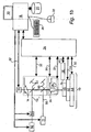
- FIG. 1b A known apparatus for imaging biological samples including fluorescent labels is shown in Figure 1b . It is similar to the apparatus shown in Figure 1a . However, instead of illumination light source 12, it includes an excitation light source 11, which generates a light beam 55. This light source is capable of exciting one or more fluorescent labels present in the sample by irradiating them with one or more specific wavebands. Filters 14 may be chosen so as to pass light emitted by labels at selected wavebands.
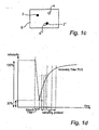
- Figure 1c illustrates attachment of a fluorescent label 2, 2' to a component of interest 4, 4' in a sample 6.
- Multiple labels may be used to provide information on the coincident localisation of labelled components, revealing, for example, the organization of the cytoskeleton of a cell.
- the excitation light source 11 employed in the apparatus of Figure 1 may be pulsed and the detector may be fitted with a gating device, so that the time taken for a fluorescent label to emit light following the pulse may be used to distinguish between different labels in a technique termed fluorescent lifetime imaging (FLIM) [ref. R. Cubedda, J. Phys. D: Appl. Phys., 2002, Vol. 35, R61-R76 ].
- FLIM fluorescent lifetime imaging
- An activating light beam 54 may enable a deeper understanding of the dynamic processes in a sample such as a living cell (in many cases this may be based on the excitation light source) to be obtained.
- the activating light beam may be directed to portions of the sample in such a manner that the intense light from this beam alters the sample and/or bleaches labels present in the sample and reduces their fluorescence. By observing the subsequent changes in the light emanating from this region, and/or elsewhere in the sample, information can be obtained on mechanisms of interaction and/or exchange of various labelled components.
- the beam may act to perforate a cell wall to allow the entry of an external agent, to dissect all or part of the cell, to destroy all or part of the cell, or to change the environment of the sample.
- FIG. 1d A graph plotting the intensity of fluorescence at a bleached region against time is shown in Figure 1d .
- the rapid recovery of fluorescence at the bleached portion suggests to what extent the label is free to return to the region.
- the mechanism, diffusion or local synthesis may be determined by estimation of diffusion rates and the mobile fraction [ref. AxelRod, Biophys. J., 1977, Vol. 18, pp. 129-131 .].
- bleaching techniques may be applied as a "bleaching protocol" comprising four phases as illustrated in Figure 1e :
- FRAP Fluorescence recovery after photo-bleaching
- Variants of the basic protocol may be used to further explore the system, by repeated bleaching of the same region, and bleaching other portions etc (FLAP, FLIP, iFRAP) [ref. J. Lippincott-Schwartz et al, see above; Phair et al, Nature, 2000, Vol. 404, pp. 604-609 .].
- a label in the sample, the sample itself or its environment may comprise a caged compound that releases an active group when illuminated by the activating light beam - a process known as uncaging [ref. J.C. Politz, Trend Cell Biol., 1999, Vol. 9, pp. 284-287 .].
- the active group may be a fluorescent label.
- the active group may not be a fluorescent label, for example the active group may instead affect the pH of the sample.
- the active group may have an indirectly visible or otherwise measurable effect on the sample.
- a technique known as pattern photo-bleaching may be using to observe changes in structure [ref. J. Ellenberg et al, Nature Supp Imaging in Cell Biol, Sept 2003, S14-S19 .].
- the bleaching process is used to introduce visually distinctive landmark patterns on part of the sample, for example a grid, movement of which may be tracked over time to understand, for example, mechanisms of membrane deformation or shear.
- Instrumentation has been developed with an adapted activating light beam to excite photo-switchable labels and force them to undergo the change in optical properties. This may, for example, be useful in revealing or hiding labelled components during the course of an experiment and in studying long term processes such as organism development [ref. D.M. Chudakov et al, Nature Biotechnology, Feb 2003, Vol. 21, pp. 191-194 .].
- photo-modification will be used to include photo-bleaching and its variants (FRAP, iFRAP, FLIP, FLAP), photo-activation, photo-switching, and pattern photo-bleaching.
- the method uses a "scamper” comprising a filter changer, an acousto-optical modulator (AOM) and a computer programmed to activate the AOM during scanning according to a freely defined image mask so that any desired pattern could be bleached ('written') into the samples and imaged ('read') at non-bleaching conditions.
- a "scamper” comprising a filter changer, an acousto-optical modulator (AOM) and a computer programmed to activate the AOM during scanning according to a freely defined image mask so that any desired pattern could be bleached ('written') into the samples and imaged ('read') at non-bleaching conditions.
- the AOM together with the illumination pinhole and scanning mirror is used to write the pattern into the specimen.
- a work station is provided, receiving input from the PMT detection means to provide a point by point image which is displaced on a computer screen.
- the point by point detected image data is also used to control the scanning mirror and via the interface shown in the "scamper" to control the irradiation conditions in respect of intensity level via the filter changer and irradiated locations via switching of the beam through the illumination pinhole under control of the AOM.
- the image (bleaching) mask is created using a set of preprogrammed graphic tools by importing a pre bleach image from the confocal scanning later microscope (as detected by the PMTs and registered by the workstation).
- the present invention provides a method of photo-modification of a sample of biological material including fluorescent labels using apparatus including processing means, comprising the steps of:
- the present invention may enable combination of imaging, measurement of one or more characteristics in the images collected, and modification of the sample, and/or labels in the sample with automatic determination of the modification parameters according to the measurement made.
- such modifications may be determined and executed "in real time", interactively, as the experiment progresses.
- This flexibility allows longer time course experiments to be conducted. It also allows rare, brief and/or rapid events to be detected and acted upon, such as all fertilisation or mutation events. Events that are difficult for a human operator to detect, such as coincident events can be detected and acted upon.
- the irradiation is provided by an illumination light source.
- the electromagnetic radiation emanating from the sample may in that case be in the form of light transmitted by the sample if illuminated from below, or reflected light if the same is illuminated from above.
- the sample includes fluorescent labels
- step (a) comprises irradiating the sample with excitation energy
- step (b) comprises detecting fluorescent radiation emitted by labels in the sample when excited by the excitation energy.
- the excitation energy may be in the form of electromagnetic energy (preferably light) or ionizing radiation, for example.
- the modification step (e) may comprise irradiating at least a portion of the sample with an energy beam. If labels are present in the sample, this beam may be selected such that the fluorescence of labels in the portion is reduced or "bleached".
- steps (a) to (e) are repeated after step (e), the period of time between the end of step (e) and the start of step (a) and/or the parameters of step (e) when repeated being dependent on said analysis by the processing means.
- the method cycles between irradiation and modification phases, and the resultant change in the appearance of the sample is detected.
- the modification step (e) comprises irradiating at least a portion of the sample with an energy beam so as to modify the optical properties of photo-switchable fluorescent labels in the portion.
- a diffusion (or other) process may be measured, and when it is determined by the processing means that the process and/or its measurement is complete, the photo-switchable labels may be "quenched", returning them to their original state, before repeating the process.
- Avoidance of repeated photo-bleaching is also beneficial as an activating light beam is often intense and its use may result in damage to the sample, or the creation of reactive species such a singlet oxygen, which may perturb the process under study, requiring sophisticated control experiments, and is thus not truly non-invasive. [Ref. D E Wolf, M Edidin, P R Dragsten, 1980, and Proc. Natl. Acad. Sci. USA 77: 2043-2045 .]
- step (e) the environmental conditions of the sample may be changed and the light emanating from the sample thereafter detected for analysis.
- An environmental change may be selected to cause labels in the sample to release a substance.
- An environmental change can be selected to modify the manner in which the sample and/or labels in the sample respond to irradiation. For example, it may change the colour of the sample or the excitation spectrum and/or emission spectrum of labels in the sample.
- the environmental change may be controlled activation light.
- the ability to modify the response of the labels in the course of a process may avoid a need to physically introduce labels during the experiment.
- the procedures for introducing the labels into the sample during an experiment are quite difficult to master, requiring additional equipment, knowledge and skill on the part of the user. Experiments often have to be repeated many times. In the case of microinjection, such procedures are also invasive to the sample. It can be seen that interactive modification of labels already present in the sample may not require physical introduction of additional labels. Labels may be activated or "switched on" in a selected region.
- the modification step may comprise modifying the physical structure of at least part of the sample. For example, this may involve forming an opening in a membrane of a selected cell in the sample to allow material to pass therethrough.
- the opening may be formed using a localised energy beam such as a laser, for example.
- a localised energy beam such as a laser
- an individual cell may be selected in the sample which is exhibiting behaviour of interest, and the user can form an opening in the cell wall to allow in material in response to that behaviour.
- the intensity of the energy beam is preferably selected such that the cell membrane is able to close or "heal" the opening shortly after its formation. Forming an opening in a cell in this way to allow the ingress of genetic material is often referred to as "transfection".
- the opening may allow agents such as labels into the cell to interact with or to highlight a specific structure and/or process in the cell, or otherwise alter its optical properties. It may allow genetic material to pass into the cell. Alternatively, material may be allowed to pass into the cell so as to kill it.
- liquid dispensing In contrast to dispensing a liquid into a sample to alter the composition of the sample as a whole, modification of an individual structure such as a cell is permitted using the technique described above. It may also be employed in combination with liquid dispensing, whereby the liquid dispensing step provides the material which passes through the opening formed by the energy beam.
- the environmental conditions of the sample to be changed may be its temperature, the concentration of a certain ion, the pH of the sample, the voltage potential of the sample, the presence of a specific enzyme, or the pressure of the sample. Labels in the sample may be sensitive to these conditions and activate when a predetermined range is reached.
- the environment of the sample is changed by altering the composition of the gas adjacent to the sample.
- labels in the sample may be activated by exposure to a predetermined gas or concentration of a predetermined gas, such as oxygen.
- the environment of the sample is changed by irradiating it with activation energy.
- the sample may be irradiated with an activation energy beam arranged to irradiate a selected portion of the sample.
- the beam may define a pattern, such as a grid, for example.
- a parameter (or parameters) of the activation energy irradiation determined by the processor may be one or more of the following examples: the start time of the irradiation; the portion of the sample to be irradiated; the waveband(s) of the energy; the power level; the duration of the irradiation; the number of repeat cycles of the activation irradiation energy; and the delay between repeat cycles.
- step (e) of a process embodying the invention may be applied to a region of the sample selected in response to the user input and/or the analysis by the processing means.
- a parameter of the modification of step (e) may be determined by the processing means with reference to data stored by the apparatus.
- step (e) is dependent on detection of the occurrence of a predetermined event in the sample by the processing means.
- data generated by the analysis by the processing means is stored by the apparatus so as to facilitate reference thereto in determining a parameter of a subsequent modification step.
- the invention further provides apparatus for photo-modification of a sample of biological material including fluorescent labels, comprising:
- the apparatus includes data storage means for storing data generated by analysis by the processing means for reference thereto by the control means in determining a parameter of a modification by the modification means.
- the apparatus may further additionally include display means for presenting to a user an indication of the electromagnetic radiation detected by the detection means, and additionally input means for enabling a user to further control at least one parameter of a modification by the modification means in response to detected radiation.
- the input means enable a user to identify a specific location in a sample for a modification by the modification means.
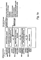
- Figures 2 to 7 represent diagrammatically protocols followed by processing means of a suitable apparatus, together with associated inputs and control outputs fed to other parts of the apparatus.
- Figure 2 shows a first example of the disclosure, which allows interactive control of photo-modification.
- a user interface allows parameters to be set and/or modified during the running of the experiment.
- the parameters control operation of the activating light source and/or ancillary devices such as the examples given in the Figure which may modify the sample, labels in the sample and/or the immediate environment of the sample.
- this protocol may be termed "FRAP on demand”.
- the system allows the user to set the parameters of the activating light beam comprising, the region of interest on the sample, the waveband(s), the power level at those wavebands, and the duration of activation.
- the user is able to image the sample and determine the start time of activation by a suitable action such as a key press.
- the user may be able to determine one or more of the duration or end of activation, the number of repeat cycles and the delay between cycles of activation, and the wavelength of the activation by a suitable action such as a key press.
- the user may be able to determine the location of activation and/or the size and shape of the irradiated region by suitable action such as manipulation of an input device such as a computer mouse.
- a label may have a temperature sensitive domain, and the sample may be held on a holder, the temperature of which may be controlled by the user via the computer to activate the labels at an appropriate point in a process.
- a label may be sensitive to gas such as oxygen, and the sample environmental unit controlled by the user via the computer to activate the labels in the course of an experiment.
- Figure 3 shows a second example that allows the use of a knowledge base to assist the user in setting and/or modifying the parameters.
- the system is as Figure 2 , and additionally allows a less experienced user to set certain high level parameters of photo-modification parameters such as the type of label to be bleached, and the system uses a knowledge base to determine the low level parameters to be used by the hardware, such as the wavelength and power level.
- a more experienced user may be able to modify the knowledge base.
- this protocol may be termed "expert FRAP”.
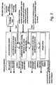
- Figure 4a shows an embodiment that uses information extracted from the images collected during the pre-modification (observation) phase to set the photo-modification parameters.
- this protocol may be termed "clever FRAP”.
- Figure 4b shows the embodiment implemented in the form of a state machine.
- Each phase in the protocol is repeated until an exit condition is met.
- the exit condition is when the image analysis module sends the start signal.
- the exit condition is when the image analysis module sends the stop signal. The additional parameters to send are not shown in this diagram.
- the system additionally allows the user to set certain parameters of the activating light beam, whilst setting others on the basis of information extracted from the data acquired during the pre-modification phase.
- the image data may be analysed to detect an event such as the motion of a component in the sample such as a cell in order to trigger the activating light beam.
- the user may be able to additionally determine the duration or end of activation by suitable action such as a key press.
- the data may be analysed either automatically according to independent claims 1, 11 or additionally by a user to:
- the data may be preprocessed to remove distortions due to deformation or motion of all or part of the sample.
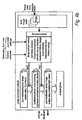
- Figure 5 shows a fourth example in which an image analysis module processes the image data acquired at each phase to determine the most appropriate parameter settings, for example, the amount of light to in order to complete photo-modification.
- the system allows the user to set certain parameters of the activating light beam, whilst the system sets others on the basis of information extracted from the data acquired during the pre-bleach phase, during the bleach phase, and during the post-bleach phase.
- the image data may be analysed to detect an event such as the change of a component in the sample in order to end a phase.
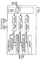
- Figure 6 shows a fifth example in which the system moves from a monitor phase to a modification phase according to the information extracted from the images collected.
- this protocol may be termed "automated FRAP".
- the system allows the switching between a monitor phase during which the sample is imaged using the excitation light source, and a modification phase, during which the sample is imaged using the activating light source.
- the transition between the two phases and parameters for the phase is determined by the analysis of the image data collected.
- Figure 7 shows a sixth example in which the system moves from a monitor phase to a modification phase according to the information extracted from the images acquired and collects the information about the sample behaviour to the activating beam at a number of parameter settings so as to set up the knowledge base mentioned in Figure 3 .
- this protocol may be termed "autoconfig FRAP".
- the system allows the control of the pre-modification phase, modification phase, post-modification phase and analysis phase as described in relation to Figure 5 .
- the parameters used at each stage are those that permit an exploration of the possible parameters of the sample so as to quickly and efficiently determine the hardware settings (laser power, modification duration, etc) by an iterative process, and these settings are passed to knowledge base mentioned in connection with Figure 3 .
- the system may be able to image during the modification phase, for example during a bleach process, to monitor the parameters of the modification.
- the sample contains one or more photo-switchable labels, so that the activating light beam is able to activate, quench or switch the label as described above in order to observe the labelled component over short (fast moving components), medium, or long time scales (rare events or configurations).
- the labels may comprise a naturally occurring fluorescent molecule such as NADH, a calcium probe such as "Fura”, and/or an antibody tagged with a fluorescent molecule and bound to a selected species.
- the labels may comprise a pair of fluorescent molecules with overlapping emission- excitation spectra of the types used in fluorescence resonant energy transfer ("FRET"), and the activating light beam may be set to photo-bleach the acceptor molecule in a region of the sample, so that the FRET process may be confirmed in that region.
- FRET fluorescence resonant energy transfer
- One of the FRET pair may be a photo-switching label, and the activating light beam may be set to switch the photo-switching label in a region of the sample, so that the FRETing process may be confirmed in that region.
- the labels may comprise a caged compound that releases an active group when illuminated by the activating light beam [ref. J.C. Politz, see above.].
- the excitation light source 11 may emit one or more spectral bands from a broadband light source such as a lamp.
- the excitation light source may be controllable to provide excitation light at more than one distinct waveband in order to distinguish between different labels. In some processes, it may be advantageous for the excitation light source to be pulsed.
- the excitation light source may be of the type employed in fluorescent speckle microscopy [ref. M.C. Adams et al, Methods, 2002, Vol. 29, pp. 29-41 .]).
- the activating light beam may be derived from the same source as the excitation light.
- the activating light beam may be:
- a localised energy beam may be employed to form an opening in a structure, such as a cell, in response to detected radiation emanating from a sample.
- a laser is used. This may be a Ti:sapphire, argon-ion or frequency-shifted ND:YAG laser for example. Alternatively, a diode laser can be employed which may be less costly.
- the same light source may be used to generate the localised energy beam to form an opening in a structure as is used to generate the activating light beam, and for the excitation light beam.
- the system may have one or more photo-detectors such as photo-multiplier tubes and a scanning arrangement of the excitation light beam and/or the emission light path to the detector and/or the detector to observe parts or all the sample.
- photo-detectors such as photo-multiplier tubes and a scanning arrangement of the excitation light beam and/or the emission light path to the detector and/or the detector to observe parts or all the sample.
- the system may have more than one imaging detector fitted with different light filtering components to distinguish between different labels.
- the detector may be fitted with a gating device, and the excitation light source may be pulsed, so that the time taken for the fluorescent label to emit light following the pulse may be used to distinguish between different labels.
- the controller may be implemented in hardware and/or software.
- the system may use a confocal principle, collecting light at a single image plane by the use of one or more pinholes and a scanning mechanism.
- a structured illumination technique may be utilised to section a sample optically at different depths [ref. M.A.A. Neil, R. Juskaitis and T. Wilson, Optical Letters, 22(24): 1905-1907, Dec. 15 1997 ].
- This may be more cost effective than a laser scanning confocal system, as it can be carried out using a conventional light microscope.
- TIRF total internal reflection
- the system may use a deconvolution principle, capturing a group of images focused at different imaging planes, and applying a deconvolution process to allow volumetric (XYZ) data to be acquired.
- Volumetric time series (XYZT) data, volumetric multi-wavelength (XYWZ) data, or volumetric multi-wavelength time series (XYWZT) data may be acquired.
- a multi-photon microscope employing a long wavelength (800-1200nm) high speed pulsed laser may form the excitation light source and/or as the activating light beam [ref. J. Pawley, Handbook of Confocal Microscopy ].
- the light or fluorescence microscope may be replaced with a simplified arrangement of sample holder, magnifying objective lens and dichroic mirror to direct light from the irradiation light source and the activating light beam to the sample, and collect the emitted light beam and to direct it to a detector.
- the fluorescence microscope may be replaced by an endoscope.
- the sample may be a homogenous population of cells such as a cell culture.
- the sample may be a heterogenous multi-cellular assembly such as a cell culture; a multi-cellular assembly such as a tissue culture; a stem cell sample; a tissue sample; an organ, such as an eye or retina, or the inside of the gut or a blood vessel; a whole animal, such as the worm C.elegans, an insect, fish, mammal or amphibian; a whole or part of a plant or fungus, a dividing cell or an embryo; one of more samples held in a multi-site carrier such as a slide, or a multi-well plate, which is scanned sequentially; or a material sample undergoing some change such as diffusion of one or more species.
Claims (14)
- Verfahren zur Photomodifizierung einer Probe biologischen Materials, das Fluoreszenzmarker enthält, unter Verwendung von Apparatur, die Verarbeitungsmittel enthält, umfassend die folgenden Schritte:(a) Bestrahlen der Probe mit Anregungsenergie;(b) Erfassen von Fluoreszenzstrahlung, die bei Anregung durch die Anregungsenergie von Markern in der Probe abgegeben wird, und Ausgeben eines Ausgangssignals als Antwort darauf;(c) Erzeugen von Bildern der Probe nach dem in Schritt (b) erfassten Licht durch Verarbeiten des Ausgangssignals mit Verarbeitungsmitteln;(d) Analysieren der Bilder mit den Verarbeitungsmitteln zur Erfassung, ob ein vorbestimmtes Ereignis in der Probe aufgetreten ist; und(e) Modifizieren der Probe und/oder Marker in der Probe durch Auslösen eines Aktivierungslichtstrahls als Antwort auf die Erfassung des vorbestimmten Ereignisses in Analyseschritt (d) durch die Verarbeitungsmittel, wobei es sich bei dem Ereignis um:handelt.- Bewegung einer Komponente in der Probe;- ein Schlüsselereigniss in dem Zellzyklus und/oder Koinzidenz von mehr als einem solchen Ereignis oder- Zelltot, Virusinvasion, Endozytose, Exozytose, Tubulierung oder Gentransfer,
- Verfahren nach Anspruch 1, wobei der Modifizierungsschritt (e) das Bestrahlen eines Abschnitts der Probe mit dem Lichtstrahl derart, dass die Fluoreszenz von Markern in dem Abschnitt reduziert ist, umfasst.
- Verfahren nach Anspruch 2, wobei Schritte (a) bis (e) nach Schritt (e) wiederholt werden, wobei die Zeitdauer zwischen dem Ende von Schritt (e) und dem Anfang von Schritt (a) und/oder die Parameter von Schritt (e) bei Wiederholung von dem Analyseschritt (d) abhängt oder abhängen.
- Verfahren nach einem vorhergehenden Anspruch, wobei der Modifizierungsschritt (e) das Bestrahlen mindestens eines Abschnitts der Probe mit dem Lichtstrahl, um die optischen Eigenschaften von photoschaltbaren Fluoreszenzmarkern in dem Abschnitt zu modifizieren, umfasst.
- Verfahren nach einem vorhergehenden Anspruch, wobei der Modifizierungsschritt (e) das Modifizieren der physikalischen Struktur von mindestens einem Teil der Probe umfasst.
- Verfahren nach Anspruch 5, umfassend das Bilden einer Öffnung in einer Membran einer ausgewählten Zelle in der Probe, damit Material durch die Öffnung in die Zelle tritt.
- Verfahren nach Anspruch 6, wobei die Öffnung unter Verwendung eines lokalisierten Energiestrahls gebildet wird.
- Verfahren nach einem vorhergehenden Anspruch, wobei der Modifizierungsschritt (e) auf einen Bereich der Probe, ausgewählt als Antwort auf die Benutzereingabe und/oder die Analyse durch die Verarbeitungsmittel, angewendet wird.
- Verfahren nach einem vorhergehenden Anspruch, wobei der mindestens eine Parameter der Modifizierung in Schritt (e) durch die Verarbeitungsmittel mit Bezug auf die durch die Vorrichtung gespeicherten Daten bestimmt wird.
- Verfahren nach einem vorhergehenden Anspruch, wobei durch die Analyse durch die Verarbeitungsmittel erzeugten Daten durch die Vorrichtung gespeichert werden, um den Bezug darauf bei der Bestimmung eines Parameters eines darauffolgenden Modifizierungsschritts zu erleichtern.
- Vorrichtung zur Photomodifizierung einer Probe (46) biologischen Materials, das Fluoreszenzmarker enthält, die Folgendes umfasst:- Bestrahlungsmittel (11) zum Bestrahlen der Probe (46) mit Anregungsenergie;- Erfassungsmittel (16) zum Erfassen von Fluoreszenzstrahlung, die bei Anregung durch die Anregungsenergie von Markern in der Probe abgegeben wird, und Ausgeben eines Ausgangssignals als Antwort darauf;- Verarbeitungsmittel (18) zum Verarbeiten des Ausgangssignals von den Erfassungsmitteln zur Erzeugung von Bildern von der Probe;- Modifizierungsmittel zur Modifizierung der Probe und/oder Markern in der Probe; und- Steuermittel (18, 24) zum Steuern der Modifizierungsmittel, um einen Aktivierungslichtstrahl als Antwort auf die Analyse der Bilder durch die Verarbeitungsmittel (18) auszulösen, wobei die Modifizierung von der Erfassung, ob ein vorbestimmtes Ereignis in der Probe aufgetreten ist, durch die Verarbeitungsmittel abhängt, wobei es sich bei dem Ereignis um:- Bewegung einer Komponente in der Probe;- ein Schlüsselereignis in dem Zellzyklus und/oder Koinzidenz von mehr als einem solchen Ereignis oder- Zelltot, Virusinvasion, Endozytose, Exozytose, Tubulierung oder Gentransfer,handelt.
- Vorrichtung nach Anspruch 11, enthaltend Datenspeichermittel zur Speicherung von Daten, die durch die Analyse durch die Verarbeitungsmittel für den Bezug darauf durch die Steuermittel bei der Bestimmung eines Parameters einer Modifizierung erzeugt werden.
- Vorrichtung nach Anspruch 11 oder Anspruch 12, enthaltend Display-Mittel zur Darstellung für einen Benutzer einer Anzeige der von den Erfassungsmitteln erfassten Fluoreszenzstrahlung, und Eingabemittel, damit ein Benutzer mindestens einen Parameter einer Modifizierung durch die Modifizierungsmittel als Antwort auf erfasste Fluoreszenzstrahlung steuern kann.
- Vorrichtung nach Anspruch 13, wobei die Eingabemittel es einem Benutzer gestatten, eine spezifische Stelle in einer Probe für eine Modifizierung durch die Modifizierungsmittel zu identifizieren.
Priority Applications (1)
| Application Number | Priority Date | Filing Date | Title |
|---|---|---|---|
| EP10182689.9A EP2375240B1 (de) | 2004-09-01 | 2005-08-17 | Verfahren zur Analyse einer Probe und Vorrichtung dafür |
Applications Claiming Priority (3)
| Application Number | Priority Date | Filing Date | Title |
|---|---|---|---|
| GBGB0419325.6A GB0419325D0 (en) | 2004-09-01 | 2004-09-01 | A method of analysing a sample including fluorescent labels and apparatus therefor |
| GB0512811A GB2418018B (en) | 2004-09-01 | 2005-06-23 | A method of analysing a sample including fluorescent labels and apparatus therefor |
| PCT/GB2005/003226 WO2006024819A2 (en) | 2004-09-01 | 2005-08-17 | A method of analysing a sample and apparatus therefor |
Related Child Applications (1)
| Application Number | Title | Priority Date | Filing Date |
|---|---|---|---|
| EP10182689.9 Division-Into | 2010-09-29 |
Publications (2)
| Publication Number | Publication Date |
|---|---|
| EP1784633A2 EP1784633A2 (de) | 2007-05-16 |
| EP1784633B1 true EP1784633B1 (de) | 2011-11-09 |
Family
ID=35079173
Family Applications (1)
| Application Number | Title | Priority Date | Filing Date |
|---|---|---|---|
| EP05768147A Active EP1784633B1 (de) | 2004-09-01 | 2005-08-17 | Verfahren zur analyse einer probe und vorrichtung dafür |
Country Status (6)
| Country | Link |
|---|---|
| EP (1) | EP1784633B1 (de) |
| JP (1) | JP5318413B2 (de) |
| KR (1) | KR101286216B1 (de) |
| AU (1) | AU2005279041B2 (de) |
| CA (1) | CA2576804C (de) |
| WO (1) | WO2006024819A2 (de) |
Families Citing this family (8)
| Publication number | Priority date | Publication date | Assignee | Title |
|---|---|---|---|---|
| JP4855139B2 (ja) | 2006-05-18 | 2012-01-18 | オリンパス株式会社 | 顕微鏡装置および細胞観察方法 |
| US8664589B2 (en) * | 2011-12-29 | 2014-03-04 | Electro Scientific Industries, Inc | Spectroscopy data display systems and methods |
| WO2014168734A1 (en) * | 2013-03-15 | 2014-10-16 | Cedars-Sinai Medical Center | Time-resolved laser-induced fluorescence spectroscopy systems and uses thereof |
| DE102016109303A1 (de) * | 2016-05-20 | 2017-11-23 | Friedrich-Schiller-Universität Jena | Lasermikroskop mit Ablationsfunktion |
| JP6033980B1 (ja) * | 2016-06-01 | 2016-11-30 | 株式会社片岡製作所 | 細胞処理システム |
| JP6541160B2 (ja) | 2017-02-13 | 2019-07-10 | 株式会社片岡製作所 | 細胞処理装置および対象物の処理方法 |
| JP6532063B2 (ja) * | 2017-02-13 | 2019-06-19 | 株式会社片岡製作所 | 細胞処理装置 |
| JP6574028B1 (ja) | 2018-06-29 | 2019-09-11 | 株式会社片岡製作所 | 細胞処理装置および細胞のレーザ処理方法 |
Family Cites Families (16)
| Publication number | Priority date | Publication date | Assignee | Title |
|---|---|---|---|---|
| US4629687A (en) * | 1982-07-29 | 1986-12-16 | Board Of Trustees Of Michigan State University | Positive selection sorting of cells |
| US5932872A (en) * | 1994-07-01 | 1999-08-03 | Jeffrey H. Price | Autofocus system for scanning microscopy having a volume image formation |
| FI98765C (fi) | 1995-01-16 | 1997-08-11 | Erkki Soini | Virtaussytometrinen menetelmä ja laite |
| FI101829B (fi) * | 1995-03-07 | 1998-08-31 | Erkki Juhani Soini | Biospesifinen määritysmenetelmä |
| WO1998049537A1 (en) * | 1997-04-25 | 1998-11-05 | Akzo Nobel N.V. | Photobleachable luminescent layers for calibration and standardization in optical microscopy |
| JP3735190B2 (ja) * | 1997-10-28 | 2006-01-18 | オリンパス株式会社 | 走査型サイトメータ |
| JPH11271220A (ja) * | 1998-03-24 | 1999-10-05 | Olympus Optical Co Ltd | 走査型顕微鏡の測定パラメータ決定方法 |
| AU5223899A (en) * | 1998-07-27 | 2000-02-21 | Ljl Biosystems, Inc. | Apparatus and methods for spectroscopic measurements |
| JP3678397B2 (ja) * | 1998-12-15 | 2005-08-03 | 富士写真フイルム株式会社 | 撮影システム |
| US20030026762A1 (en) * | 1999-05-05 | 2003-02-06 | Malmros Mark K. | Bio-spectral imaging system and methods for diagnosing cell disease state |
| WO2000071028A1 (en) * | 1999-05-26 | 2000-11-30 | Photogen, Inc. | Improved methods and apparatus for multi-photon photo-activation and detection of molecular agents |
| ATE249657T1 (de) * | 2000-04-06 | 2003-09-15 | European Molecular Biology Lab Embl | Rechnergesteuertes mikroskop |
| JP3999662B2 (ja) * | 2000-12-14 | 2007-10-31 | オリンパス株式会社 | 蛍光分析装置および蛍光分析方法 |
| JP3734769B2 (ja) * | 2001-11-09 | 2006-01-11 | アイダエンジニアリング株式会社 | 蛍光強度測定方法および装置 |
| GB0224067D0 (en) * | 2002-10-16 | 2002-11-27 | Perkinelmer Uk Ltd | Improvements in and relating to imaging |
| AU2003291104A1 (en) * | 2002-11-18 | 2004-06-15 | Genospectra, Inc. | Uncaging devices |
-
2005
- 2005-08-17 AU AU2005279041A patent/AU2005279041B2/en active Active
- 2005-08-17 KR KR1020077005978A patent/KR101286216B1/ko active IP Right Grant
- 2005-08-17 CA CA2576804A patent/CA2576804C/en active Active
- 2005-08-17 WO PCT/GB2005/003226 patent/WO2006024819A2/en active Application Filing
- 2005-08-17 EP EP05768147A patent/EP1784633B1/de active Active
- 2005-08-17 JP JP2007528957A patent/JP5318413B2/ja active Active
Also Published As
| Publication number | Publication date |
|---|---|
| AU2005279041A1 (en) | 2006-03-09 |
| CA2576804A1 (en) | 2006-03-09 |
| JP2008511824A (ja) | 2008-04-17 |
| WO2006024819A3 (en) | 2006-05-18 |
| EP1784633A2 (de) | 2007-05-16 |
| WO2006024819A8 (en) | 2006-09-08 |
| AU2005279041B2 (en) | 2011-04-07 |
| KR20070050085A (ko) | 2007-05-14 |
| JP5318413B2 (ja) | 2013-10-16 |
| WO2006024819A2 (en) | 2006-03-09 |
| CA2576804C (en) | 2013-10-15 |
| KR101286216B1 (ko) | 2013-07-15 |
Similar Documents
| Publication | Publication Date | Title |
|---|---|---|
| US7671345B2 (en) | Method of analysing a sample and apparatus therefor | |
| EP1784633B1 (de) | Verfahren zur analyse einer probe und vorrichtung dafür | |
| van Munster et al. | Fluorescence lifetime imaging microscopy (FLIM) | |
| JP5307539B2 (ja) | 生体試料撮像方法および生体試料撮像装置 | |
| US7906768B2 (en) | Imaging of biological samples | |
| US7782457B2 (en) | Optical microscopy with phototransformable optical labels | |
| US10288863B2 (en) | Optogenetics microscope | |
| JP5746161B2 (ja) | 顕微鏡画像における蛍光の評価方法 | |
| WO2007038260A2 (en) | Systems and methods for force-fluorescence microscopy | |
| US20240035950A1 (en) | Method and microscope for recording trajectories of individual particles in a sample | |
| Lippincott-Schwartz | Bridging structure and process in developmental biology through new imaging technologies | |
| Helmchen | Two-photon functional imaging of neuronal activity | |
| Buranachai et al. | Fluorescence lifetime imaging in living cells | |
| US7521696B2 (en) | Method and apparatus for analyzing a dynamic sample | |
| Sancataldo et al. | Two-photon imaging | |
| Palikaras et al. | Multiphoton fluorescence light microscopy | |
| Foo et al. | Fluorescence correlation and cross-correlation spectroscopy using fluorescent proteins for measurements of biomolecular processes in living organisms | |
| Elgass et al. | The fluorescence lifetime of BRI1-GFP as probe for the noninvasive determination of the membrane potential in living cells | |
| JP2006003154A (ja) | 試料解析装置 | |
| Bhupathi et al. | Single Molecule Imaging Using State-of-the-Art Microscopy Techniques | |
| Parasar et al. | Microscopic Tools for Cell Imaging | |
| French | Overview of fluorescence imaging for biophotonics | |
| KR101234143B1 (ko) | 동적 샘플을 분석하기 위한 방법 및 장치 | |
| Denham | Cellular signalling in sight: Technical challenges in microscopy | |
| Merriman III | Stimulated emission depletion (STED) microscopy and Pacific Orange dye optimization for H9c2 COX-1 imaging via indirect immunocytochemistry |
Legal Events
| Date | Code | Title | Description |
|---|---|---|---|
| PUAI | Public reference made under article 153(3) epc to a published international application that has entered the european phase |
Free format text: ORIGINAL CODE: 0009012 |
|
| 17P | Request for examination filed |
Effective date: 20070127 |
|
| AK | Designated contracting states |
Kind code of ref document: A2 Designated state(s): AT BE BG CH CY CZ DE DK EE ES FI FR GB GR HU IE IS IT LI LT LU LV MC NL PL PT RO SE SI SK TR |
|
| DAX | Request for extension of the european patent (deleted) | ||
| 17Q | First examination report despatched |
Effective date: 20071123 |
|
| GRAP | Despatch of communication of intention to grant a patent |
Free format text: ORIGINAL CODE: EPIDOSNIGR1 |
|
| GRAS | Grant fee paid |
Free format text: ORIGINAL CODE: EPIDOSNIGR3 |
|
| GRAA | (expected) grant |
Free format text: ORIGINAL CODE: 0009210 |
|
| RBV | Designated contracting states (corrected) |
Designated state(s): AT BE BG CH CY CZ DE DK EE ES FI FR GR HU IE IS IT LI LT LU LV MC NL PL PT RO SE SI SK TR |
|
| AK | Designated contracting states |
Kind code of ref document: B1 Designated state(s): AT BE BG CH CY CZ DE DK EE ES FI FR GR HU IE IS IT LI LT LU LV MC NL PL PT RO SE SI SK TR |
|
| REG | Reference to a national code |
Ref country code: CH Ref legal event code: EP |
|
| REG | Reference to a national code |
Ref country code: IE Ref legal event code: FG4D |
|
| REG | Reference to a national code |
Ref country code: DE Ref legal event code: R096 Ref document number: 602005031113 Country of ref document: DE Effective date: 20120126 |
|
| REG | Reference to a national code |
Ref country code: NL Ref legal event code: VDEP Effective date: 20111109 |
|
| LTIE | Lt: invalidation of european patent or patent extension |
Effective date: 20111109 |
|
| PG25 | Lapsed in a contracting state [announced via postgrant information from national office to epo] |
Ref country code: LT Free format text: LAPSE BECAUSE OF FAILURE TO SUBMIT A TRANSLATION OF THE DESCRIPTION OR TO PAY THE FEE WITHIN THE PRESCRIBED TIME-LIMIT Effective date: 20111109 Ref country code: IS Free format text: LAPSE BECAUSE OF FAILURE TO SUBMIT A TRANSLATION OF THE DESCRIPTION OR TO PAY THE FEE WITHIN THE PRESCRIBED TIME-LIMIT Effective date: 20120309 |
|
| PG25 | Lapsed in a contracting state [announced via postgrant information from national office to epo] |
Ref country code: PT Free format text: LAPSE BECAUSE OF FAILURE TO SUBMIT A TRANSLATION OF THE DESCRIPTION OR TO PAY THE FEE WITHIN THE PRESCRIBED TIME-LIMIT Effective date: 20120309 Ref country code: BE Free format text: LAPSE BECAUSE OF FAILURE TO SUBMIT A TRANSLATION OF THE DESCRIPTION OR TO PAY THE FEE WITHIN THE PRESCRIBED TIME-LIMIT Effective date: 20111109 Ref country code: SE Free format text: LAPSE BECAUSE OF FAILURE TO SUBMIT A TRANSLATION OF THE DESCRIPTION OR TO PAY THE FEE WITHIN THE PRESCRIBED TIME-LIMIT Effective date: 20111109 Ref country code: LV Free format text: LAPSE BECAUSE OF FAILURE TO SUBMIT A TRANSLATION OF THE DESCRIPTION OR TO PAY THE FEE WITHIN THE PRESCRIBED TIME-LIMIT Effective date: 20111109 Ref country code: NL Free format text: LAPSE BECAUSE OF FAILURE TO SUBMIT A TRANSLATION OF THE DESCRIPTION OR TO PAY THE FEE WITHIN THE PRESCRIBED TIME-LIMIT Effective date: 20111109 Ref country code: PL Free format text: LAPSE BECAUSE OF FAILURE TO SUBMIT A TRANSLATION OF THE DESCRIPTION OR TO PAY THE FEE WITHIN THE PRESCRIBED TIME-LIMIT Effective date: 20111109 Ref country code: SI Free format text: LAPSE BECAUSE OF FAILURE TO SUBMIT A TRANSLATION OF THE DESCRIPTION OR TO PAY THE FEE WITHIN THE PRESCRIBED TIME-LIMIT Effective date: 20111109 Ref country code: GR Free format text: LAPSE BECAUSE OF FAILURE TO SUBMIT A TRANSLATION OF THE DESCRIPTION OR TO PAY THE FEE WITHIN THE PRESCRIBED TIME-LIMIT Effective date: 20120210 |
|
| PG25 | Lapsed in a contracting state [announced via postgrant information from national office to epo] |
Ref country code: CY Free format text: LAPSE BECAUSE OF FAILURE TO SUBMIT A TRANSLATION OF THE DESCRIPTION OR TO PAY THE FEE WITHIN THE PRESCRIBED TIME-LIMIT Effective date: 20111109 |
|
| PG25 | Lapsed in a contracting state [announced via postgrant information from national office to epo] |
Ref country code: SK Free format text: LAPSE BECAUSE OF FAILURE TO SUBMIT A TRANSLATION OF THE DESCRIPTION OR TO PAY THE FEE WITHIN THE PRESCRIBED TIME-LIMIT Effective date: 20111109 Ref country code: DK Free format text: LAPSE BECAUSE OF FAILURE TO SUBMIT A TRANSLATION OF THE DESCRIPTION OR TO PAY THE FEE WITHIN THE PRESCRIBED TIME-LIMIT Effective date: 20111109 Ref country code: BG Free format text: LAPSE BECAUSE OF FAILURE TO SUBMIT A TRANSLATION OF THE DESCRIPTION OR TO PAY THE FEE WITHIN THE PRESCRIBED TIME-LIMIT Effective date: 20120209 Ref country code: CZ Free format text: LAPSE BECAUSE OF FAILURE TO SUBMIT A TRANSLATION OF THE DESCRIPTION OR TO PAY THE FEE WITHIN THE PRESCRIBED TIME-LIMIT Effective date: 20111109 Ref country code: EE Free format text: LAPSE BECAUSE OF FAILURE TO SUBMIT A TRANSLATION OF THE DESCRIPTION OR TO PAY THE FEE WITHIN THE PRESCRIBED TIME-LIMIT Effective date: 20111109 |
|
| PG25 | Lapsed in a contracting state [announced via postgrant information from national office to epo] |
Ref country code: RO Free format text: LAPSE BECAUSE OF FAILURE TO SUBMIT A TRANSLATION OF THE DESCRIPTION OR TO PAY THE FEE WITHIN THE PRESCRIBED TIME-LIMIT Effective date: 20111109 Ref country code: IT Free format text: LAPSE BECAUSE OF FAILURE TO SUBMIT A TRANSLATION OF THE DESCRIPTION OR TO PAY THE FEE WITHIN THE PRESCRIBED TIME-LIMIT Effective date: 20111109 |
|
| PLBE | No opposition filed within time limit |
Free format text: ORIGINAL CODE: 0009261 |
|
| STAA | Information on the status of an ep patent application or granted ep patent |
Free format text: STATUS: NO OPPOSITION FILED WITHIN TIME LIMIT |
|
| REG | Reference to a national code |
Ref country code: AT Ref legal event code: MK05 Ref document number: 533041 Country of ref document: AT Kind code of ref document: T Effective date: 20111109 |
|
| 26N | No opposition filed |
Effective date: 20120810 |
|
| REG | Reference to a national code |
Ref country code: DE Ref legal event code: R097 Ref document number: 602005031113 Country of ref document: DE Effective date: 20120810 |
|
| PG25 | Lapsed in a contracting state [announced via postgrant information from national office to epo] |
Ref country code: AT Free format text: LAPSE BECAUSE OF FAILURE TO SUBMIT A TRANSLATION OF THE DESCRIPTION OR TO PAY THE FEE WITHIN THE PRESCRIBED TIME-LIMIT Effective date: 20111109 |
|
| REG | Reference to a national code |
Ref country code: CH Ref legal event code: PL |
|
| PG25 | Lapsed in a contracting state [announced via postgrant information from national office to epo] |
Ref country code: MC Free format text: LAPSE BECAUSE OF NON-PAYMENT OF DUE FEES Effective date: 20120831 |
|
| PG25 | Lapsed in a contracting state [announced via postgrant information from national office to epo] |
Ref country code: CH Free format text: LAPSE BECAUSE OF NON-PAYMENT OF DUE FEES Effective date: 20120831 Ref country code: LI Free format text: LAPSE BECAUSE OF NON-PAYMENT OF DUE FEES Effective date: 20120831 Ref country code: ES Free format text: LAPSE BECAUSE OF FAILURE TO SUBMIT A TRANSLATION OF THE DESCRIPTION OR TO PAY THE FEE WITHIN THE PRESCRIBED TIME-LIMIT Effective date: 20120220 |
|
| REG | Reference to a national code |
Ref country code: FR Ref legal event code: ST Effective date: 20130430 |
|
| REG | Reference to a national code |
Ref country code: IE Ref legal event code: MM4A |
|
| PG25 | Lapsed in a contracting state [announced via postgrant information from national office to epo] |
Ref country code: FI Free format text: LAPSE BECAUSE OF FAILURE TO SUBMIT A TRANSLATION OF THE DESCRIPTION OR TO PAY THE FEE WITHIN THE PRESCRIBED TIME-LIMIT Effective date: 20111109 |
|
| PG25 | Lapsed in a contracting state [announced via postgrant information from national office to epo] |
Ref country code: IE Free format text: LAPSE BECAUSE OF NON-PAYMENT OF DUE FEES Effective date: 20120817 |
|
| PG25 | Lapsed in a contracting state [announced via postgrant information from national office to epo] |
Ref country code: FR Free format text: LAPSE BECAUSE OF NON-PAYMENT OF DUE FEES Effective date: 20120831 |
|
| PG25 | Lapsed in a contracting state [announced via postgrant information from national office to epo] |
Ref country code: TR Free format text: LAPSE BECAUSE OF FAILURE TO SUBMIT A TRANSLATION OF THE DESCRIPTION OR TO PAY THE FEE WITHIN THE PRESCRIBED TIME-LIMIT Effective date: 20111109 |
|
| PG25 | Lapsed in a contracting state [announced via postgrant information from national office to epo] |
Ref country code: LU Free format text: LAPSE BECAUSE OF NON-PAYMENT OF DUE FEES Effective date: 20120817 |
|
| PG25 | Lapsed in a contracting state [announced via postgrant information from national office to epo] |
Ref country code: HU Free format text: LAPSE BECAUSE OF FAILURE TO SUBMIT A TRANSLATION OF THE DESCRIPTION OR TO PAY THE FEE WITHIN THE PRESCRIBED TIME-LIMIT Effective date: 20050817 |
|
| P01 | Opt-out of the competence of the unified patent court (upc) registered |
Effective date: 20230526 |
|
| PGFP | Annual fee paid to national office [announced via postgrant information from national office to epo] |
Ref country code: DE Payment date: 20230620 Year of fee payment: 19 |