EP1782943B1 - Verfahren und Pulverpresse mit Meßsystem zur Bestimmung einer Referenz bei der Pulverpresse - Google Patents
Verfahren und Pulverpresse mit Meßsystem zur Bestimmung einer Referenz bei der Pulverpresse Download PDFInfo
- Publication number
- EP1782943B1 EP1782943B1 EP06021575.3A EP06021575A EP1782943B1 EP 1782943 B1 EP1782943 B1 EP 1782943B1 EP 06021575 A EP06021575 A EP 06021575A EP 1782943 B1 EP1782943 B1 EP 1782943B1
- Authority
- EP
- European Patent Office
- Prior art keywords
- die
- plate
- punch
- attaching
- die plate
- Prior art date
- Legal status (The legal status is an assumption and is not a legal conclusion. Google has not performed a legal analysis and makes no representation as to the accuracy of the status listed.)
- Not-in-force
Links
Images
Classifications
-
- B—PERFORMING OPERATIONS; TRANSPORTING
- B30—PRESSES
- B30B—PRESSES IN GENERAL
- B30B11/00—Presses specially adapted for forming shaped articles from material in particulate or plastic state, e.g. briquetting presses, tabletting presses
- B30B11/005—Control arrangements
-
- B—PERFORMING OPERATIONS; TRANSPORTING
- B30—PRESSES
- B30B—PRESSES IN GENERAL
- B30B15/00—Details of, or accessories for, presses; Auxiliary measures in connection with pressing
- B30B15/0094—Press load monitoring means
-
- B—PERFORMING OPERATIONS; TRANSPORTING
- B30—PRESSES
- B30B—PRESSES IN GENERAL
- B30B15/00—Details of, or accessories for, presses; Auxiliary measures in connection with pressing
- B30B15/02—Dies; Inserts therefor; Mounting thereof; Moulds
- B30B15/028—Loading or unloading of dies, platens or press rams
Definitions
- the invention relates to a method for determining a reference in a powder press according to claim 1 or 2.
- the invention further relates to a powder press with measuring system for determining a reference according to claim 3.
- the usual construction of a powder press is the arrangement of a die on a die plate resting on a machine frame. At least one upper and one lower punch cooperate with the die, which are preferably driven by a hydraulic drive. It is known to attach the stamp on a so-called adapter plate, which is guided vertically in suitable guide columns or the like. The punches are either attached directly to the adapter plate or via an adapter, which in turn is attached to the adapter plate.
- the stamps are assigned to force measuring devices.
- the distance measurements are made with the corresponding distance measuring systems.
- pressure measuring doses are assigned to the punches.
- the dimensions which the punches and the die have are of course known or can be determined.
- a reference is required, since the knowledge of the dimensions of the upper punch, for example, does not say anything about its precise height position in the baling chamber, for example in the upper end position.
- the referencing is usually from a is subject to fluctuations per homing of one to two hundredths of a millimeter.
- defined locations of the stamp are referenced to a defined position of the die. All traversing movements of the stamp refer to this reference.
- JP 2001269843 It has become known to determine the center position of a rotating tool by automatically measuring the deviation of the center of a rotating spindle. For this purpose, a reference tool is rotated with the known tool diameter and with the aid of a contactless sensor, the maximum and minimum circumferential position of the reference tool is measured during its rotation.
- JP 63093564A described in which a reference tool in the form of a grinding tool of known dimensions is mounted on a rotating spindle. It is determined at which position a reference plate is touched.
- US 4718842 A discloses a method according to the preamble of claims 1 and 2 and a powder press with measuring system according to the preamble of claim 3.
- the invention has for its object to provide a method and a powder press with measuring system for determining a reference in a powder press, which can be performed automatically and which allows automatic tool change with sufficiently accurate reproducibility of the determined reference values.
- a reference die and at least one reference punch are made.
- the reference tools do not have to be modeled on the molds in terms of their configuration.
- the decisive factor is that they have a previously known dimension and a defined edge. For the reference stamp, this is the top edge and at the reference die also the upper edge. The production costs for the reference tools are therefore limited.
- the position of the upper edge of the reference die is measured, and the measured position value is stored in a memory of the measuring device and / or an electronic control device of the powder press.
- Optical or similar measuring devices which, in the case described, have an accuracy of up to one micron per e.g. 50 mm length are known.
- the light source is usually a laser and the receiving device is a photosensitive line.
- the upper adapter plate is moved down with the reference punch previously attached to it until the edge of the reference punch reaches the stored position of the upper edge of the reference die.
- the sum of the reference punch dimension and the die dimension corresponds to the distance between the upper adapter plate and the die plate. This distance value is taken over and stored by the machine control. All further movements are detected via the already existing position measuring devices.
- the determination of the reference for the lower punch proceeds in a similar manner by raising the lower adapter plate with the reference punch until the upper edge of the reference punch reaches the stored position value of the upper edge of the die.
- the difference of the reference punch and the reference die results in the distance dimension of the lower adapter plate to the die plate.
- the exact distance between the upper and / or lower adapter plate and the surface of the die plate can thus be determined exactly for a given powder press.
- At least one reference punch and a reference die are also used.
- both must be installed simultaneously, and it is determined by means of an already existing force measuring device, when the reference punch comes to rest with the reference template.
- the reference die has a precise surface on which the reference punch can be placed. The contact is determined by the fact that a minimum force must be achieved. This must be so small that a deformation of the reference tools does not yet occur. Again, the sum or difference of the reference tools gives the distance of the adapter plates.
- an optical measuring system which operates on the principle of shadow measurement.
- the surface of the die plate on which the dies are to be mounted is precisely ground.
- the position measurement of the upper edge of the reference die a precise position relative to the ground surface of the die plate.
- the above statements relate to the so-called ejection method in which the die plate is stationary.
- the lower punch is stationary and the die plate is actuated via an adapter plate.
- the distance of this adapter plate must be referenced to the lower die, which is done in the same manner described.
- the optical measuring system can no longer be arranged on the Matrizen- or base plate, but must otherwise be stationary to determine the distance of the female adapter plate from the lower punch or the lower die holder.
- the starting point is the stationary position of the lower punch or one Reference sub-stamps to which the measured positions of the reference punch or reference die refer.
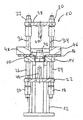
- the single figure shows a side view schematically a powder press with a measuring system according to the invention.
- a powder press 10 has a frame 12 which carries a die plate 14.
- the die plate is used to attach a die (not shown).
- a base plate 16 is mounted with a ground surface.
- hydraulic cylinders (not shown) are mounted, which engage a lower adapter plate 22 and an upper adapter plate 28 along vertical guide columns or rails 24, 26, 34, 36 with guides 18, 20, 30, 32 or guide carriage are guided precisely vertically.
- An upper adapter plate 28 is actuated by means of hydraulic cylinders 30, 32 and is vertically guided along upper guide columns 34, 36.
- the adapter plates 22, 28 are usually used for attachment of an adapter and connectable to the adapter upper and lower punch.
- Upper and lower stamps can also consist of several stamps. This is well known.
- the lower punch When pressing, as is known, filled in the mold cavity of the die powder and with the help of the drives upper and lower punches are retracted into the mold space of the die, the lower punch is known to be already during the filling process within the die.
- the way cover the top and bottom punches measured by means of a suitable, not shown here accurate Meßwegvorraum.
- the force acting on the punches forces is determined by means of force measuring devices, not shown.
- a reference upper punch 40 is attached to the upper adapter plate 28.
- a reference die 42 is attached to the die plate 14, and a reference die 44 is attached to the lower adapter plate.
- the reference punches 40, 44 and their reference die have precisely known dimensions.
- a transmitter 46 of an optical measuring system is arranged on the surface of the base plate 16.
- a receiver 48 of the measuring system is arranged on the base plate 16.
- the transmitter 46 generates a light band 50.
- the position of the upper edge of the reference matrix 42 can be determined. This value is saved.
- the reference die is removed, and the reference upper punch 40 is moved down until its lower edge reaches the measured position of the upper edge of the reference die 42. Due to the fact that the reference punch and reference die dimensions are known, the distance between the adapter plate 28 and the die plate 14 or the base plate 16 is known from the sum of the two dimensions. Since the adapters or the molds are known in their dimensions, it requires no further referencing during installation of tools and tool change, because, as mentioned, the location of the Adapter plate 28 relative to the die plate or base plate 14, 16 is known.
- the method described here can also be used in the withdrawal process.
- the reference punch 44 is then stationary and the base plate 24 is actuated by hydraulic cylinders.
- the measurement system 46, 48 is otherwise to be stationarily arranged to determine and store the position of the reference die, and to designate the measured position of the reference die 40 and movable reference die 42 thereon, e.g. the lower punch 44 is removed to move the upper punch so far that its lower edge is brought into the stored position of the upper edge of the lower punch 44. The same is done with respect to the die 42.
Landscapes
- Engineering & Computer Science (AREA)
- Mechanical Engineering (AREA)
- Powder Metallurgy (AREA)
- Length Measuring Devices By Optical Means (AREA)
Description
- Die Erfindung bezieht sich auf ein Verfahren zur Bestimmung einer Referenz bei einer Pulverpresse nach dem Patentanspruch 1 oder 2. Die Erfindung bezieht sich ferner auf eine Pulverpresse mit Meßsystem zur Bestimmung einer Referenz nach Patentanspruch 3.
- Der übliche Aufbau einer Pulverpresse ist die Anordnung einer Matrize (Preßform) auf einer Matrizenplatte, die auf einem Maschinengestell ruht. Mit der Matrize wirken mindestens ein Ober- und ein Unterstempel zusammen, die vorzugsweise über einen hydraulischen Antrieb angetrieben sind. Es ist bekannt, die Stempel an einer sogenannten Adapterplatte anzubringen, die in geeigneten Führungssäulen oder dergleichen vertikal geführt ist. Die Stempel werden entweder unmittelbar an der Adapterplatte angebracht oder über einen Adapter, der seinerseits an der Adapterplatte befestigt ist.
- Es ist ferner bekannt, das Verpressen des Pulvers in der Matrize nach Kraft- und Wegparametern durchzuführen. Daher werden den Stempeln Kraftmeßvorrichtungen zugeordnet. Die Wegmessungen erfolgen mit entsprechenden Wegmeßsystemen. Zur Kraftmessung werden zumeist Druckmeßdosen den Stempeln zugeordnet.
- Die Abmessungen, welche die Stempel und die Matrize aufweisen, sind naturgemäß bekannt bzw. können ermittelt werden. Um eine sehr präzise Messung der Wege vornehmen zu können, bedarf es gleichwohl einer Referenz, da die Kenntnis der Abmessungen z.B. des Oberstempels noch nichts über seine präzise Höhenposition im Preßraum besagt, etwa in der oberen Endlage. Im Stand der Technik wird der Referenziervorgang üblicherweise von einem unterliegt Schwankungen pro Referenziervorgang von Ein- bis Zweihundertstel Millimeter. Hierbei werden definierte Stellen der Stempel auf eine definierte Stelle der Matrize referenziert. Alle Verfahrbewegungen der Stempel beziehen sich auf diese Referenz. Bei einem Werkzeugwechsel müssen jedesmal die Stempel neu referenziert werden, weil sich die Stempel- und Matrizenabmessungen ändern. Unter Umständen werden mehrere Ober- und Unterstempel und z.B. ein Mittelstift eingesetzt, die jeweils referenziert werden müssen. Ein derartiger Referenziervorgang ist daher zeitlich aufwendig und gewährleistet nicht die gewünschte Reproduzierbarkeit. Ist ein automatischer Wechsel der Formwerkzeuge gewünscht, kann ein manuelles Referenzieren nicht durchgeführt werden.
- Aus
EP 1 074 380A ist für eine Exzenterpresse bekannt geworden, Kalibrierdaten dadurch zu erstellen, dass die Höhenpositionen einer Referenzform ermittelt werden und zwar einmal bei einer minimalen und einmal bei einer maximalen Belastung sowie auch bei Belastungen zwischen den Extremwerten. - Aus
EP 0 607 498 A1 ist bekannt, zur automatisierten Hubeinstellung eines Stanzwerkzeugs die Position des Stanzwerkzeugs mit Hilfe eines optischen Senders und Empfängers zu ermitteln. Aus der auf das Werkstück hingerichteten Bewegung des Stanzwerkzeugs, dem Zeitpunkt der Unterbrechung des Strahlengangs in Verbindung mit über einen Weggeber gelieferten Weginformationen kann unabhängig von der vorher ermittelten Werkzeuglänge der obere Totpunkt des Standhubes automatisch festgelegt werden. - Aus
JP 2001269843 JP 63093564A - Aus
JP 03189098A -
US 4718842 A offenbart ein Verfahren gemäß dem Oberbegriff der Ansprüche 1 und 2 und eine Pulverpresse mit Meßsystem gemäß dem Oberbegriff des Anspruchs 3. - Der Erfindung liegt die Aufgabe zugrunde, ein Verfahren und eine Pulverpresse mit Meßsystem zur Bestimmung einer Referenz bei einer Pulverpresse anzugeben, das automatisch durchgeführt werden kann und das einen automatischen Werkzeugwechsel erlaubt bei gleichzeitig ausreichend genauer Reproduzierbarkeit der ermittelten Referenzwerte.
- Diese Aufgabe wird durch die Verfahren nach den Patentansprüchen 1 und 2 und durch die Pulverpresse mit Meßsystem nach dem Anspruch 3 gelöst.
- Bei dem Verfahren nach Patentanspruch 1 werden eine Referenzmatrize und mindestens ein Referenzstempel gefertigt. Die Referenzwerkzeuge müssen von der Konfiguration her nicht den Formwerkzeugen nachgebildet werden. Entscheidend ist lediglich, daß sie eine vorbekannte Abmessung haben sowie eine definierte Kante. Beim Referenzstempel ist dies die obere Kante und bei der Referenzmatrize ebenfalls die obere Kante. Der Herstellungsaufwand für die Referenzwerkzeuge hält sich daher in Grenzen.
- Mit Hilfe einer auf der Matrizenplatte der Pulverpresse angeordneten optischen Meßvorrichtung wird die Position der Oberkante der Referenzmatrize gemessen, und der gemessene Positionswert wird in einem Speicher der Meßeinrichtung und/oder einer elektronischen Steuervorrichtung der Pulverpresse gespeichert. Optische oder ähnliche Meßvorrichtungen, welche in dem beschriebenen Fall eine Genauigkeit bis zu einem µm pro z.B. 50 mm Länge gewährleisten, sind bekannt. Die Lichtquelle ist zumeist ein Laser und die Empfangsvorrichtung eine lichtempfindliche Zeile.
- Anschließend wird die Referenzmatrize entfernt. Die obere Adapterplatte wird mit zuvor daran angebrachtem Referenzstempel nach unten gefahren, bis die Kante des Referenzstempels die gespeicherte Position der Oberkante der Referenzmatrize erreicht hat. Die Summe des Referenzstempelmaßes und des Matrizenmaßes entspricht dem Abstand der oberen Adapterplatte zur Matrizenplatte. Dieser Abstandswert wird von der Maschinensteuerung übernommen und gespeichert. Alle weiteren Verfahrbewegungen werden über die ohnehin vorhandenen Wegmeßeinrichtungen erfaßt.
- Die Bestimmung der Referenz für den Unterstempel verläuft in ähnlicher Weise, indem die untere Adapterplatte mit dem Referenzstempel hochgefahren wird, bis die Oberkante des Referenzstempels den gespeicherten Positionswert der Oberkante der Matrize erreicht. Die Differenz des Referenzstempels und der Referenzmatrize ergibt das Abstandsmaß der unteren Adapterplatte zur Matrizenplatte.
- Mit Hilfe des beschriebenen Verfahrens läßt sich mithin für eine gegebene Pulverpresse der exakte Abstand zwischen oberer bzw. unterer Adapterplatte und Oberfläche der Matrizenplatte exakt bestimmen. Beim Einbau von Formwerkzeugen bedarf es keiner erneuten Referenzierung, da die Abmessungen der neuen Formwerkzeuge bekannt sind und somit auch z.B. der Abstand der Unterkante des Oberstempels von der Oberkante der Matrize. Somit entfällt jeder Referenziervorgang beim Werkzeugwechsel, so daß der Werkzeugwechsel automatisch durchgeführt werden kann. Dadurch wird der Aufwand bei einem Werkzeugwechsel drastisch verringert.
- Bei der Lösung nach Patentanspruch 2 werden ebenfalls mindestens ein Referenzstempel und eine Referenzmatrize verwendet. Hierbei müssen beide gleichzeitig eingebaut sein, und es wird mit Hilfe einer ohnehin vorhandenen Kraftmeßvorrichtung festgestellt, wann der Referenzstempel mit der Referenzmatrize zur Anlage kommt. Hierzu ist notwendig, daß die Referenzmatrize eine präzise Oberfläche hat, auf welcher der Referenzstempel aufsetzen kann. Der Kontakt wird dadurch festgestellt, daß eine minimale Kraft erreicht werden muß. Diese muß so klein sein, daß eine Verformung an den Referenzwerkzeugen noch nicht eintritt. Auch hier ergibt die Summe bzw. Differenz der Referenzwerkzeuge den Abstand der Adapterplatten.
- Bei dem Verfahren nach Patentanspruch 1 wird, wie erläutert, ein optisches Meßsystem verwendet, das nach dem Prinzip der Schattenmessung arbeitet. Um hier ausreichend präzise Werte zu erhalten, ist die Oberfläche der Matrizenplatte, auf welcher die Matrizen anzubringen sind, präzise geschliffen. Somit hat z.B. die Positionsvermessung der Oberkante der Referenzmatrize eine präzise Lage relativ zur geschliffenen Fläche der Matrizenplatte.
- Wie schon erläutert, braucht der beschriebene Referenziervorgang nur ein einziges Mal durchgeführt zu werden. Ein erneutes Referenzieren ist erst nach Modifikationen am Adapter, an dessen Anbindung an der Adapterplatte oder am Wegmeßsystem erforderlich. Solange jedoch der Adapter eingebaut bleibt und nur unterschiedliche Werkzeuge angebracht werden, entfällt jeder weitere Referenziervorgang.
- Die obigen Ausführungen beziehen sich auf das sogenannte Ausstoßverfahren, bei dem die Matrizenplatte stationär ist. Beim sogenannten Auszugverfahren ist der Unterstempel stationär und die Matrizenplatte wird über eine Adapterplatte betätigt. In diesem Fall muß der Abstand dieser Adapterplatte zum Unterstempel referenziert werden, was in der gleichen beschriebenen Art und Weise erfolgt. Dabei kann das optische Meßsystem nicht mehr auf der Matrizen- oder Grundplatte angeordnet sein, sondern muß anderweitig stationär sein, um den Abstand der Matrizen-Adapterplatte von dem Unterstempel bzw. der Unterstempelhalterung zu bestimmen. Ausgangspunkt ist dabei die stationäre Position des Unterstempels bzw. eines Referenzunterstempels, auf die sich die gemessenen Positionen von Referenzoberstempel bzw. Referenzmatrize beziehen.
- Die Erfindung wird nachfolgend anhand einer Zeichnung näher erläutert.
- Die einzige Figur zeigt in Seitenansicht schematisch eine Pulverpresse mit einem Meßsystem nach der Erfindung.
- Eine Pulverpresse 10 weist ein Gestell 12 auf, das eine Matrizenplatte 14 trägt. Die Matrizenplatte dient zur Anbringung einer Matrize (nicht gezeigt). Auf der Matrizenplatte 14 ist eine Grundplatte 16 mit geschliffener Oberfläche angebracht. An einem Gestell (nicht gezeigt) sind auf gegenüberliegenden Seiten Hydraulikzylinder (nicht gezeigt) angebracht, welche an einer unteren Adapterplatte 22 und einer oberen Adapterplatte 28 angreifen, die entlang von vertikalen Führungssäulen oder -schienen 24, 26, 34, 36 mit Führungen 18, 20, 30, 32 oder Führungsschlitten präzise vertikal geführt sind. Eine obere Adapterplatte 28 wird mittels Hydraulikzylindern 30, 32 betätigt und ist entlang von oberen Führungssäulen 34, 36 vertikal geführt. Die Adapterplatten 22, 28 dienen üblicherweise zur Anbringung eines Adapters und eines mit dem Adapter verbindbaren Ober- und Unterstempels. Dabei können Ober- und Unterstempel auch aus mehreren Stempeln bestehen. Dies ist allgemein bekannt. Beim Verpressen wird, wie bekannt, in den Formhohlraum der Matrize Pulver eingefüllt und mit Hilfe der Antriebe werden Ober- und Unterstempel in den Formraum der Matrize eingefahren, wobei der Unterstempel bekanntlich sich schon während des Befüllvorgangs innerhalb der Matrize befindet. Während des Formvorgangs wird der Weg, den Ober- und Unterstempel zurücklegen, mit Hilfe einer geeigneten, hier nicht gezeigten präzisen Meßwegvorrichtung gemessen. Außerdem wird mit Hilfe von nicht gezeigten Kraftmeßvorrichtungen die an den Stempeln wirkenden Kräfte ermittelt.
- In der Figur ist an der oberen Adapterplatte 28 ein Referenzoberstempel 40 angebracht. An der Matrizenplatte 14 ist eine Referenzmatrize 42 angebracht, und an der unteren Adapterplatte ist ein Referenzunterstempel 44 angebracht. Die Referenzstempel 40, 44 und ihre Referenzmatrize weisen präzise bekannte Abmessungen auf.
- Auf der Oberfläche der Grundplatte 16 ist ein Sender 46 eines optischen Meßsystems angeordnet. Auf der gegenüberliegenden Seite ist auf der Grundplatte 16 ein Empfänger 48 des Meßsystems angeordnet. Der Sender 46 erzeugt ein Lichtband 50. Mit Hilfe des Empfängers 48 kann die Position der oberen Kante der Referenzmatrize 42 festgestellt werden. Dieser Wert wird gespeichert. Anschließend wird die Referenzmatrize ausgebaut, und der Referenzoberstempel 40 nach unten gefahren, bis seine Unterkante die gemessene Position der Oberkante der Referenzmatrize 42 erreicht. Dadurch, daß die Referenzstempel- und Referenzmatrizenmaße bekannt sind, ergibt sich aus der Summe der beiden Abmaße der Abstand zwischen der Adapterplatte 28 und der Matrizenplatte 14 bzw. der Grundplatte 16 bekannt. Da auch die Adapter bzw. die Formwerkzeuge in ihren Abmessungen bekannt sind, bedarf es beim Einbau der Werkzeuge und beim Werkzeugwechsel keines weiteren Referenziervorgangs, denn, wie erwähnt, die Lage der Adapterplatte 28 relativ zur Matrizenplatte bzw. Grundplatte 14, 16 ist bekannt.
- In gleicher Weise wird bezüglich des Unterstempels 44 verfahren. Dieser wird bei entfernter Referenzmatrize 42 nach oben gefahren bis seine Oberkante die gemessene Position der Oberkante der Referenzmatrize 42 erreicht. Damit ist auch der Abstand der unteren Adapterplatte 22 von der Oberseite der Matrizenplatte bzw. der Grundplatte 16 bekannt.
- Das hier beschriebene Verfahren kann auch bei dem Abzugverfahren zur Anwendung kommen. Referenzstempel 44 ist dann stationär und die Grundplatte 24 wird von Hydraulikzylindern betätigt. Das Meßsystem 46, 48 ist anderweitig stationär anzuordnen, um die Position des Referenzunterstempels zu bestimmen und zu speichern und die gemessene Position des Referenzoberstempels 40 und der beweglichen Referenzmatrize 42 darauf zu bezeichnen, indem z.B. der Unterstempel 44 entfernt wird, um den Oberstempel soweit zu verfahren, daß seine Unterkante in die gespeicherte Position der Oberkante des Unterstempels 44 gebracht wird. Ähnliches erfolgt in Bezug auf die Matrize 42.
Claims (3)
- Verfahren zur Bestimmung einer Referenz bei einer Pulverpresse, die eine Matrizenplatte (14) zur Anbringung einer Matrize und eine von einem hydraulischen, mechanisch, elektrisch oder ähnlichem Antrieb betätigbare oberen Adapterplatte (28) zur Anbringung eines Oberstempels, eine von einem hydraulischen Antrieb betätigbare untere Adapterplatte (22) zur Anbringung eines Unterstempels oder der Matrizenplatte und mindestens ein Wegmeßsystem für den Ober- und den Unterstempel bzw. der Matrizenplatte (14) aufweist, gekennzeichnet durch die folgenden Schritte:- Es werden eine Referenzmatrize (42) und mindestens ein Referenzstempel (40, 44) vorbekannter Abmessung und mit definierter Kante geeignet für einen Referenziervorgang gefertigt,- auf der Matrizenplatte (14) wird die Referenzmatrize (42) angebracht,- mit einer hilfsweise auf einer Grund- oder der Matrizenplatte (16, 14) angeordneten optischen Meßvorrichtung (46, 48) wird die Position der Oberkante der Referenzmatrize (42) gemessen und der Positionswert gespeichert,- die Referenzmatrize (42) wird entfernt,- die Adapterplatte (28, 22) mit zuvor angebrachtem Referenzstempel (40, 44) wird in Richtung Matrizenplatte (14) gefahren, bis die Unterkante oder Oberkante des Referenzstempels (40, 42) die gespeicherte Position der Oberkante der Referenzmatrize (42) erreicht hat,- es wird die Summe des Referenzmatrizenmaßes und des Referenzstempelmaßes als Abstand der Adapterplatte (28, 22) zur Matrizenplatte (14) gebildet und gespeichert.
- Verfahren zur Bestimmung einer Referenz bei einer Pulverpresse, die eine Matrizenplatte (14) zur Anbringung einer Matrize und eine von einem hydraulischen Antrieb betätigbare oberen Adapterplatte (28) zur Anbringung eines Oberstempels, eine von einem hydraulischen Antrieb betätigbare untere Adapterplattc (22) zur Anbringung eines Unterstempels oder der Matrizenplatte (14) und mindestens ein Wegmeßsystem für den Ober- und den Unterstempel sowie eine Kraftmeßvorrichtung für Ober- und Unterstempel bzw. der Matrizenplatte aufweist, gekennzeichnet durch die folgenden Schritte:- Es werden eine Referenzmatrize (42) und mindestens ein Referenzstempel (40, 44) vorbekannter Abmessung und mit definierter Kante geeignet für einen Referenziervorgang gefertigt,- die Referenzmatrize (42) wird auf einer Grund- oder der Matrizenplatte (14) und der Referenzstempel (40, 44) wird an der Adapterplatte (28, 22) angebracht,- der Referenzstempel (40, 44) wird gegen die Referenzmatrize (42) gefahren, bis ein vorgegebener Wert für die Kraft erreicht wird, wenn der Referenzstempel (40, 44) auf der Referenzmatrize (42) zur Anlage kommt,- wobei die Kraft so klein ist, dass eine Verformung der Referenzwerkzeuge noch nicht eintritt und- es wird die Summe des Referenzmatrizenmaßes und des Referenzstempelmaßes als Abstand der Adapterplatte zur Matrizenplatte gebildet und gespeichert.
- Pulverpresse mit Meßsystem geeignet zur Bildung einer Referenz in der Pulverpresse, die eine Grundplatte zur Anbringung einer Matrizenplatte (14) und eine von einem hydraulischen Antrieb betätigbare Adapterplatte (28) zur Anbringung eines Oberstempels, eine von einem hydraulischen Antrieb betätigbare untere Adapterplatte (22) zur Anbringung eines Unterstempels oder der Grundplatte (16), mindestens ein Wegmeßsystem für Ober- und Unterstempel oder der Matrizenplatte (14) und eine Kraftmeßvorrichtung für Ober- und/oder Unterstempel oder die Matrizenplatte (14) aufweist, gekennzeichnet durch folgende Merkmale:- eine geschliffene Oberfläche der Matrizenplatte (14) und der Grundplatte (16)- eine Referenzmatrize (42) vorbekannter Abmessung und mit definierter Kante, geeignet für einen Referenziervorgang und zur Anbringung auf der Matrizenplatte (14)- cin Referenzstempel (40) vorbekannter Abmessung und mit definierter Kante, geeignet für einen Referenziervorgang und geeignet zur Anbringung an der oberen oder unteren Adapterplatte (28, 22) und- ein auf der Oberfläche der Grundplatte (16) oder Matrizenplatte anbringbares optisches Meßsystem (46, 48).
Applications Claiming Priority (1)
| Application Number | Priority Date | Filing Date | Title |
|---|---|---|---|
| DE102005052158A DE102005052158B4 (de) | 2005-11-02 | 2005-11-02 | Verfahren und Meßsystem zur Bildung einer Referenz bei einer Pulverpresse |
Publications (3)
| Publication Number | Publication Date |
|---|---|
| EP1782943A2 EP1782943A2 (de) | 2007-05-09 |
| EP1782943A3 EP1782943A3 (de) | 2009-06-03 |
| EP1782943B1 true EP1782943B1 (de) | 2014-12-17 |
Family
ID=37574907
Family Applications (1)
| Application Number | Title | Priority Date | Filing Date |
|---|---|---|---|
| EP06021575.3A Not-in-force EP1782943B1 (de) | 2005-11-02 | 2006-10-14 | Verfahren und Pulverpresse mit Meßsystem zur Bestimmung einer Referenz bei der Pulverpresse |
Country Status (3)
| Country | Link |
|---|---|
| US (1) | US7803294B2 (de) |
| EP (1) | EP1782943B1 (de) |
| DE (1) | DE102005052158B4 (de) |
Families Citing this family (4)
| Publication number | Priority date | Publication date | Assignee | Title |
|---|---|---|---|---|
| DE102011100618A1 (de) | 2010-12-30 | 2012-07-05 | Sms Meer Gmbh | Pulverpresse oder Pulverpressenadapter sowie Verfahren zum Betrieb einer Pulverpresse |
| DE102012013227B4 (de) | 2012-07-04 | 2014-12-31 | Sms Meer Gmbh | Pulverpresse |
| DE102012013229B4 (de) | 2012-07-04 | 2014-10-09 | Sms Meer Gmbh | Pulverpresse |
| CH716048B1 (de) | 2019-04-09 | 2024-02-15 | Dietmar Kramer Dr Sc Techn Eth Phd | Verfahren sowie eine Messeinrichtung zum Ausmessen von Utensilien für Pressen. |
Citations (3)
| Publication number | Priority date | Publication date | Assignee | Title |
|---|---|---|---|---|
| US4718842A (en) * | 1984-09-11 | 1988-01-12 | Philippe Labbe | Automatic press for controlling the force on each movable plate |
| EP0365447A1 (de) * | 1988-10-20 | 1990-04-25 | Adl Automation Societe A Responsabilite Limitee : | Verfahren und Vorrichtung zum Zusammenpressen und Steuern der Zusammenpressung von pulverförmigen Materialien und Presse zur Anwendung in diesem Verfahren |
| NL1006041C2 (nl) * | 1997-05-13 | 1998-11-19 | Struyk Verwo Groep B V | Werkwijze en inrichting voor het vervaardigen van betonnen voorwerpen. |
Family Cites Families (14)
| Publication number | Priority date | Publication date | Assignee | Title |
|---|---|---|---|---|
| JPS57196313A (en) * | 1981-05-26 | 1982-12-02 | Mitsubishi Electric Corp | Automatic compensating device for backlash amount |
| JPH064220B2 (ja) * | 1986-10-07 | 1994-01-19 | 株式会社新潟鐵工所 | 数値制御研削盤における自動砥石寸法測定方法 |
| JPH03189098A (ja) * | 1989-12-18 | 1991-08-19 | Toshiba Corp | プレス装置 |
| JP3189098B2 (ja) | 1992-03-06 | 2001-07-16 | コニカ株式会社 | カラー画像形成方法 |
| DE4301309C2 (de) * | 1993-01-20 | 1994-10-13 | Behrens Ag C | Schneidpresse |
| JP3648054B2 (ja) * | 1998-04-15 | 2005-05-18 | オークマ株式会社 | 主軸又はアタッチメント補正値の自動決定方法 |
| FR2791834B1 (fr) | 1999-03-29 | 2001-06-08 | Valeo Securite Habitacle | Systeme pour securiser une transmission bidirectionnelle de donnees entre un identifiant et un identifieur |
| DE19919693C2 (de) * | 1999-04-30 | 2001-08-23 | Fette Wilhelm Gmbh | Verfahren zur Positionsbestimmung eines Preßstempels einer Pulverpresse |
| TW553063U (en) * | 1999-08-03 | 2003-09-11 | Kosmek Kk | Device for obtaining calibration data of mechanical press, and load display device for mechanical press |
| JP2001269843A (ja) * | 2000-03-27 | 2001-10-02 | Okuma Corp | 回転工具の中心位置測定方法 |
| DE10041225C2 (de) * | 2000-08-22 | 2002-10-24 | Freudenberg Carl Kg | Verfahren und Kalibriereinrichtung zur Einstellung der Presshöhe an Anschlagpressen mittels eines Kalibriereinsatzes |
| US6567761B1 (en) * | 2000-08-31 | 2003-05-20 | Rockwell Automation Technologies, Inc. | In-die part measurement system |
| DE10151858A1 (de) * | 2001-10-24 | 2003-05-08 | Dorst Masch & Anlagen | Verfahren zum Einstellen bzw. Überwachen eines Pressen-Werkzeugs und Pressen-Werkzeug bzw. Pressen-Steuereinrichtung dafür |
| JP4490027B2 (ja) * | 2002-05-17 | 2010-06-23 | 株式会社放電精密加工研究所 | プレス機 |
-
2005
- 2005-11-02 DE DE102005052158A patent/DE102005052158B4/de not_active Expired - Fee Related
-
2006
- 2006-10-14 EP EP06021575.3A patent/EP1782943B1/de not_active Not-in-force
- 2006-10-24 US US11/585,601 patent/US7803294B2/en active Active
Patent Citations (3)
| Publication number | Priority date | Publication date | Assignee | Title |
|---|---|---|---|---|
| US4718842A (en) * | 1984-09-11 | 1988-01-12 | Philippe Labbe | Automatic press for controlling the force on each movable plate |
| EP0365447A1 (de) * | 1988-10-20 | 1990-04-25 | Adl Automation Societe A Responsabilite Limitee : | Verfahren und Vorrichtung zum Zusammenpressen und Steuern der Zusammenpressung von pulverförmigen Materialien und Presse zur Anwendung in diesem Verfahren |
| NL1006041C2 (nl) * | 1997-05-13 | 1998-11-19 | Struyk Verwo Groep B V | Werkwijze en inrichting voor het vervaardigen van betonnen voorwerpen. |
Also Published As
| Publication number | Publication date |
|---|---|
| US20070096351A1 (en) | 2007-05-03 |
| DE102005052158A1 (de) | 2007-05-03 |
| EP1782943A2 (de) | 2007-05-09 |
| DE102005052158B4 (de) | 2008-01-03 |
| EP1782943A3 (de) | 2009-06-03 |
| US7803294B2 (en) | 2010-09-28 |
Similar Documents
| Publication | Publication Date | Title |
|---|---|---|
| DE69306640T2 (de) | Methode und Apparat zur Haltekraftmessung an einem Druckring einer Presse | |
| DE3840395C2 (de) | Steuerung einer Blechbearbeitungspresse | |
| DE69710101T2 (de) | Biegepresse | |
| DE3843593C2 (de) | ||
| DE69002143T2 (de) | Stanzmaschine. | |
| CH649726A5 (de) | Winkelmessvorrichtung fuer abkantpresse. | |
| EP2110266B1 (de) | Verfahren und Vorrichtung zur Erzeugung eines Zeichens in einer Werkstückoberfläche durch Prägen | |
| EP3274110B1 (de) | Umformwerkzeug und verfahren zur optimierung einer platinenumformung in einem umformwerkzeug | |
| DE3925608C2 (de) | Werkzeugmaschine | |
| DE102023128853A1 (de) | Gerät zur automatischen innendurchmessermessung | |
| WO2015150130A1 (de) | Verfahren und federwindemaschine zur herstellung von schraubenfedern durch federwinden | |
| DE102011055630B4 (de) | Kniehebelpresse mit Verstellvorrichtung für ein Werkzeugteil | |
| DE212013000044U1 (de) | Transferzentrum zur spanenden Bearbeitung | |
| EP0589240A1 (de) | Liegende Metallstrangpresse | |
| DE102006020213B4 (de) | Presse zur Herstellung von Preßlingen aus Pulvermaterial | |
| DE102014213888A1 (de) | Justiervorrichtung und Justierverfahren | |
| DE102005052158B4 (de) | Verfahren und Meßsystem zur Bildung einer Referenz bei einer Pulverpresse | |
| DE102016120195A1 (de) | Presseneinrichtung | |
| EP0294765A1 (de) | Präzisionsstanzautomat und zugehöriges Verfahren zum Werkzeugwechsel | |
| WO2020207645A1 (de) | Verfahren sowie eine messeinrichtung zum ausmessen bzw. kalibrieren von utensilien bei pressen | |
| DE69030307T2 (de) | Verfahren zum Positionieren eines Bauteils, das mit einer Platte verbunden ist oder einen Teil derselben bildet, sowie Vorrichtung zum Durchführen des Verfahren, und nach diesem Verfahren hergestellte Platte | |
| EP1635972B1 (de) | Verfahren und vorrichtung zum umformen von werkstücken | |
| DE102014110507A1 (de) | Pressverfahren mit Kompensation von Positionierfehlern bei einem Pressvorgang und Presse zur Durchführung eines solchen Verfahrens | |
| DE202006002052U1 (de) | Markierungsvorrichtung | |
| EP0607498B1 (de) | Verfahren zum Betrieb einer Schneidpresse und Schneidpresse |
Legal Events
| Date | Code | Title | Description |
|---|---|---|---|
| PUAI | Public reference made under article 153(3) epc to a published international application that has entered the european phase |
Free format text: ORIGINAL CODE: 0009012 |
|
| AK | Designated contracting states |
Kind code of ref document: A2 Designated state(s): AT BE BG CH CY CZ DE DK EE ES FI FR GB GR HU IE IS IT LI LT LU LV MC NL PL PT RO SE SI SK TR |
|
| AX | Request for extension of the european patent |
Extension state: AL BA HR MK YU |
|
| PUAL | Search report despatched |
Free format text: ORIGINAL CODE: 0009013 |
|
| AK | Designated contracting states |
Kind code of ref document: A3 Designated state(s): AT BE BG CH CY CZ DE DK EE ES FI FR GB GR HU IE IS IT LI LT LU LV MC NL PL PT RO SE SI SK TR |
|
| AX | Request for extension of the european patent |
Extension state: AL BA HR MK RS |
|
| 17P | Request for examination filed |
Effective date: 20090522 |
|
| 17Q | First examination report despatched |
Effective date: 20090917 |
|
| AKX | Designation fees paid |
Designated state(s): AT BE BG CH CY CZ DE DK EE ES FI FR GB GR HU IE IS IT LI LT LU LV MC NL PL PT RO SE SI SK TR |
|
| RIC1 | Information provided on ipc code assigned before grant |
Ipc: B30B 15/00 20060101ALI20140618BHEP Ipc: B30B 15/02 20060101ALI20140618BHEP Ipc: B30B 11/00 20060101AFI20140618BHEP |
|
| GRAP | Despatch of communication of intention to grant a patent |
Free format text: ORIGINAL CODE: EPIDOSNIGR1 |
|
| INTG | Intention to grant announced |
Effective date: 20140725 |
|
| GRAS | Grant fee paid |
Free format text: ORIGINAL CODE: EPIDOSNIGR3 |
|
| GRAA | (expected) grant |
Free format text: ORIGINAL CODE: 0009210 |
|
| AK | Designated contracting states |
Kind code of ref document: B1 Designated state(s): AT BE BG CH CY CZ DE DK EE ES FI FR GB GR HU IE IS IT LI LT LU LV MC NL PL PT RO SE SI SK TR |
|
| REG | Reference to a national code |
Ref country code: GB Ref legal event code: FG4D Free format text: NOT ENGLISH |
|
| REG | Reference to a national code |
Ref country code: CH Ref legal event code: EP |
|
| REG | Reference to a national code |
Ref country code: IE Ref legal event code: FG4D Free format text: LANGUAGE OF EP DOCUMENT: GERMAN |
|
| REG | Reference to a national code |
Ref country code: AT Ref legal event code: REF Ref document number: 701561 Country of ref document: AT Kind code of ref document: T Effective date: 20150115 |
|
| REG | Reference to a national code |
Ref country code: DE Ref legal event code: R096 Ref document number: 502006014117 Country of ref document: DE Effective date: 20150129 |
|
| PG25 | Lapsed in a contracting state [announced via postgrant information from national office to epo] |
Ref country code: FI Free format text: LAPSE BECAUSE OF FAILURE TO SUBMIT A TRANSLATION OF THE DESCRIPTION OR TO PAY THE FEE WITHIN THE PRESCRIBED TIME-LIMIT Effective date: 20141217 Ref country code: LT Free format text: LAPSE BECAUSE OF FAILURE TO SUBMIT A TRANSLATION OF THE DESCRIPTION OR TO PAY THE FEE WITHIN THE PRESCRIBED TIME-LIMIT Effective date: 20141217 |
|
| REG | Reference to a national code |
Ref country code: LT Ref legal event code: MG4D |
|
| PG25 | Lapsed in a contracting state [announced via postgrant information from national office to epo] |
Ref country code: LV Free format text: LAPSE BECAUSE OF FAILURE TO SUBMIT A TRANSLATION OF THE DESCRIPTION OR TO PAY THE FEE WITHIN THE PRESCRIBED TIME-LIMIT Effective date: 20141217 Ref country code: GR Free format text: LAPSE BECAUSE OF FAILURE TO SUBMIT A TRANSLATION OF THE DESCRIPTION OR TO PAY THE FEE WITHIN THE PRESCRIBED TIME-LIMIT Effective date: 20150318 Ref country code: SE Free format text: LAPSE BECAUSE OF FAILURE TO SUBMIT A TRANSLATION OF THE DESCRIPTION OR TO PAY THE FEE WITHIN THE PRESCRIBED TIME-LIMIT Effective date: 20141217 |
|
| PG25 | Lapsed in a contracting state [announced via postgrant information from national office to epo] |
Ref country code: NL Free format text: LAPSE BECAUSE OF FAILURE TO SUBMIT A TRANSLATION OF THE DESCRIPTION OR TO PAY THE FEE WITHIN THE PRESCRIBED TIME-LIMIT Effective date: 20141217 |
|
| PG25 | Lapsed in a contracting state [announced via postgrant information from national office to epo] |
Ref country code: RO Free format text: LAPSE BECAUSE OF FAILURE TO SUBMIT A TRANSLATION OF THE DESCRIPTION OR TO PAY THE FEE WITHIN THE PRESCRIBED TIME-LIMIT Effective date: 20141217 Ref country code: SK Free format text: LAPSE BECAUSE OF FAILURE TO SUBMIT A TRANSLATION OF THE DESCRIPTION OR TO PAY THE FEE WITHIN THE PRESCRIBED TIME-LIMIT Effective date: 20141217 Ref country code: CZ Free format text: LAPSE BECAUSE OF FAILURE TO SUBMIT A TRANSLATION OF THE DESCRIPTION OR TO PAY THE FEE WITHIN THE PRESCRIBED TIME-LIMIT Effective date: 20141217 Ref country code: EE Free format text: LAPSE BECAUSE OF FAILURE TO SUBMIT A TRANSLATION OF THE DESCRIPTION OR TO PAY THE FEE WITHIN THE PRESCRIBED TIME-LIMIT Effective date: 20141217 Ref country code: ES Free format text: LAPSE BECAUSE OF FAILURE TO SUBMIT A TRANSLATION OF THE DESCRIPTION OR TO PAY THE FEE WITHIN THE PRESCRIBED TIME-LIMIT Effective date: 20141217 |
|
| PG25 | Lapsed in a contracting state [announced via postgrant information from national office to epo] |
Ref country code: IS Free format text: LAPSE BECAUSE OF FAILURE TO SUBMIT A TRANSLATION OF THE DESCRIPTION OR TO PAY THE FEE WITHIN THE PRESCRIBED TIME-LIMIT Effective date: 20150417 Ref country code: PL Free format text: LAPSE BECAUSE OF FAILURE TO SUBMIT A TRANSLATION OF THE DESCRIPTION OR TO PAY THE FEE WITHIN THE PRESCRIBED TIME-LIMIT Effective date: 20141217 |
|
| REG | Reference to a national code |
Ref country code: DE Ref legal event code: R097 Ref document number: 502006014117 Country of ref document: DE |
|
| PLBE | No opposition filed within time limit |
Free format text: ORIGINAL CODE: 0009261 |
|
| STAA | Information on the status of an ep patent application or granted ep patent |
Free format text: STATUS: NO OPPOSITION FILED WITHIN TIME LIMIT |
|
| REG | Reference to a national code |
Ref country code: FR Ref legal event code: PLFP Year of fee payment: 10 |
|
| PG25 | Lapsed in a contracting state [announced via postgrant information from national office to epo] |
Ref country code: DK Free format text: LAPSE BECAUSE OF FAILURE TO SUBMIT A TRANSLATION OF THE DESCRIPTION OR TO PAY THE FEE WITHIN THE PRESCRIBED TIME-LIMIT Effective date: 20141217 |
|
| 26N | No opposition filed |
Effective date: 20150918 |
|
| PG25 | Lapsed in a contracting state [announced via postgrant information from national office to epo] |
Ref country code: SI Free format text: LAPSE BECAUSE OF FAILURE TO SUBMIT A TRANSLATION OF THE DESCRIPTION OR TO PAY THE FEE WITHIN THE PRESCRIBED TIME-LIMIT Effective date: 20141217 |
|
| PG25 | Lapsed in a contracting state [announced via postgrant information from national office to epo] |
Ref country code: LU Free format text: LAPSE BECAUSE OF FAILURE TO SUBMIT A TRANSLATION OF THE DESCRIPTION OR TO PAY THE FEE WITHIN THE PRESCRIBED TIME-LIMIT Effective date: 20151014 |
|
| REG | Reference to a national code |
Ref country code: CH Ref legal event code: PL |
|
| PG25 | Lapsed in a contracting state [announced via postgrant information from national office to epo] |
Ref country code: MC Free format text: LAPSE BECAUSE OF FAILURE TO SUBMIT A TRANSLATION OF THE DESCRIPTION OR TO PAY THE FEE WITHIN THE PRESCRIBED TIME-LIMIT Effective date: 20141217 |
|
| REG | Reference to a national code |
Ref country code: IE Ref legal event code: MM4A |
|
| PG25 | Lapsed in a contracting state [announced via postgrant information from national office to epo] |
Ref country code: LI Free format text: LAPSE BECAUSE OF NON-PAYMENT OF DUE FEES Effective date: 20151031 Ref country code: CH Free format text: LAPSE BECAUSE OF NON-PAYMENT OF DUE FEES Effective date: 20151031 |
|
| REG | Reference to a national code |
Ref country code: FR Ref legal event code: PLFP Year of fee payment: 11 |
|
| PG25 | Lapsed in a contracting state [announced via postgrant information from national office to epo] |
Ref country code: IE Free format text: LAPSE BECAUSE OF NON-PAYMENT OF DUE FEES Effective date: 20151014 |
|
| PG25 | Lapsed in a contracting state [announced via postgrant information from national office to epo] |
Ref country code: HU Free format text: LAPSE BECAUSE OF FAILURE TO SUBMIT A TRANSLATION OF THE DESCRIPTION OR TO PAY THE FEE WITHIN THE PRESCRIBED TIME-LIMIT; INVALID AB INITIO Effective date: 20061014 Ref country code: BG Free format text: LAPSE BECAUSE OF FAILURE TO SUBMIT A TRANSLATION OF THE DESCRIPTION OR TO PAY THE FEE WITHIN THE PRESCRIBED TIME-LIMIT Effective date: 20141217 |
|
| PG25 | Lapsed in a contracting state [announced via postgrant information from national office to epo] |
Ref country code: CY Free format text: LAPSE BECAUSE OF FAILURE TO SUBMIT A TRANSLATION OF THE DESCRIPTION OR TO PAY THE FEE WITHIN THE PRESCRIBED TIME-LIMIT Effective date: 20141217 |
|
| PG25 | Lapsed in a contracting state [announced via postgrant information from national office to epo] |
Ref country code: TR Free format text: LAPSE BECAUSE OF FAILURE TO SUBMIT A TRANSLATION OF THE DESCRIPTION OR TO PAY THE FEE WITHIN THE PRESCRIBED TIME-LIMIT Effective date: 20141217 |
|
| REG | Reference to a national code |
Ref country code: FR Ref legal event code: PLFP Year of fee payment: 12 |
|
| PG25 | Lapsed in a contracting state [announced via postgrant information from national office to epo] |
Ref country code: PT Free format text: LAPSE BECAUSE OF FAILURE TO SUBMIT A TRANSLATION OF THE DESCRIPTION OR TO PAY THE FEE WITHIN THE PRESCRIBED TIME-LIMIT Effective date: 20141217 |
|
| REG | Reference to a national code |
Ref country code: FR Ref legal event code: PLFP Year of fee payment: 13 |
|
| PGFP | Annual fee paid to national office [announced via postgrant information from national office to epo] |
Ref country code: AT Payment date: 20181019 Year of fee payment: 13 Ref country code: DE Payment date: 20181211 Year of fee payment: 13 |
|
| PGFP | Annual fee paid to national office [announced via postgrant information from national office to epo] |
Ref country code: BE Payment date: 20181022 Year of fee payment: 13 Ref country code: FR Payment date: 20181023 Year of fee payment: 13 Ref country code: IT Payment date: 20181022 Year of fee payment: 13 Ref country code: GB Payment date: 20181025 Year of fee payment: 13 |
|
| REG | Reference to a national code |
Ref country code: DE Ref legal event code: R119 Ref document number: 502006014117 Country of ref document: DE |
|
| PG25 | Lapsed in a contracting state [announced via postgrant information from national office to epo] |
Ref country code: DE Free format text: LAPSE BECAUSE OF NON-PAYMENT OF DUE FEES Effective date: 20200501 |
|
| REG | Reference to a national code |
Ref country code: BE Ref legal event code: MM Effective date: 20191031 |
|
| REG | Reference to a national code |
Ref country code: AT Ref legal event code: MM01 Ref document number: 701561 Country of ref document: AT Kind code of ref document: T Effective date: 20191014 |
|
| PG25 | Lapsed in a contracting state [announced via postgrant information from national office to epo] |
Ref country code: BE Free format text: LAPSE BECAUSE OF NON-PAYMENT OF DUE FEES Effective date: 20191031 |
|
| GBPC | Gb: european patent ceased through non-payment of renewal fee |
Effective date: 20191014 |
|
| PG25 | Lapsed in a contracting state [announced via postgrant information from national office to epo] |
Ref country code: IT Free format text: LAPSE BECAUSE OF NON-PAYMENT OF DUE FEES Effective date: 20191014 Ref country code: FR Free format text: LAPSE BECAUSE OF NON-PAYMENT OF DUE FEES Effective date: 20191031 Ref country code: GB Free format text: LAPSE BECAUSE OF NON-PAYMENT OF DUE FEES Effective date: 20191014 |
|
| PG25 | Lapsed in a contracting state [announced via postgrant information from national office to epo] |
Ref country code: AT Free format text: LAPSE BECAUSE OF NON-PAYMENT OF DUE FEES Effective date: 20191014 |