EP1782075B1 - Procede de revêtement differentiel d'un substrat - Google Patents
Procede de revêtement differentiel d'un substrat Download PDFInfo
- Publication number
- EP1782075B1 EP1782075B1 EP05818193.4A EP05818193A EP1782075B1 EP 1782075 B1 EP1782075 B1 EP 1782075B1 EP 05818193 A EP05818193 A EP 05818193A EP 1782075 B1 EP1782075 B1 EP 1782075B1
- Authority
- EP
- European Patent Office
- Prior art keywords
- array
- coating
- camera
- holes
- agent
- Prior art date
- Legal status (The legal status is an assumption and is not a legal conclusion. Google has not performed a legal analysis and makes no representation as to the accuracy of the status listed.)
- Active
Links
- 239000011248 coating agent Substances 0.000 title claims description 167
- 238000000034 method Methods 0.000 title claims description 160
- 238000000576 coating method Methods 0.000 title claims description 151
- 239000000758 substrate Substances 0.000 title claims description 71
- 229920001223 polyethylene glycol Polymers 0.000 claims description 91
- 239000002202 Polyethylene glycol Substances 0.000 claims description 85
- 239000003795 chemical substances by application Substances 0.000 claims description 61
- 239000007788 liquid Substances 0.000 claims description 48
- 239000002981 blocking agent Substances 0.000 claims description 21
- 239000000203 mixture Substances 0.000 claims description 19
- 238000004891 communication Methods 0.000 claims description 12
- 230000006854 communication Effects 0.000 claims description 12
- 239000007800 oxidant agent Substances 0.000 claims description 9
- 230000003213 activating effect Effects 0.000 claims description 5
- 230000002209 hydrophobic effect Effects 0.000 description 70
- 239000012530 fluid Substances 0.000 description 60
- 239000000523 sample Substances 0.000 description 60
- 239000010408 film Substances 0.000 description 57
- BLRPTPMANUNPDV-UHFFFAOYSA-N Silane Chemical compound [SiH4] BLRPTPMANUNPDV-UHFFFAOYSA-N 0.000 description 56
- 229910000077 silane Inorganic materials 0.000 description 55
- 239000000463 material Substances 0.000 description 54
- 238000006243 chemical reaction Methods 0.000 description 52
- 239000003153 chemical reaction reagent Substances 0.000 description 49
- 238000011068 loading method Methods 0.000 description 47
- 230000008569 process Effects 0.000 description 43
- 239000000243 solution Substances 0.000 description 39
- XLYOFNOQVPJJNP-UHFFFAOYSA-N water Substances O XLYOFNOQVPJJNP-UHFFFAOYSA-N 0.000 description 35
- LFQSCWFLJHTTHZ-UHFFFAOYSA-N Ethanol Chemical compound CCO LFQSCWFLJHTTHZ-UHFFFAOYSA-N 0.000 description 34
- 238000000151 deposition Methods 0.000 description 32
- 230000008021 deposition Effects 0.000 description 31
- 239000010410 layer Substances 0.000 description 29
- 239000000126 substance Substances 0.000 description 26
- 238000012986 modification Methods 0.000 description 24
- 238000003491 array Methods 0.000 description 23
- 125000000524 functional group Chemical group 0.000 description 22
- 230000004048 modification Effects 0.000 description 21
- 238000012546 transfer Methods 0.000 description 20
- 230000033001 locomotion Effects 0.000 description 18
- 238000011282 treatment Methods 0.000 description 17
- 230000000903 blocking effect Effects 0.000 description 16
- 230000003647 oxidation Effects 0.000 description 16
- 238000007254 oxidation reaction Methods 0.000 description 16
- 230000006320 pegylation Effects 0.000 description 16
- 239000007787 solid Substances 0.000 description 16
- 125000000391 vinyl group Chemical group [H]C([*])=C([H])[H] 0.000 description 16
- 229920002554 vinyl polymer Polymers 0.000 description 16
- 238000004422 calculation algorithm Methods 0.000 description 15
- ABTOQLMXBSRXSM-UHFFFAOYSA-N silicon tetrafluoride Chemical compound F[Si](F)(F)F ABTOQLMXBSRXSM-UHFFFAOYSA-N 0.000 description 14
- 239000010935 stainless steel Substances 0.000 description 14
- 229910001220 stainless steel Inorganic materials 0.000 description 14
- 239000013598 vector Substances 0.000 description 14
- 229910000831 Steel Inorganic materials 0.000 description 13
- 238000002844 melting Methods 0.000 description 13
- 239000010959 steel Substances 0.000 description 13
- 238000013459 approach Methods 0.000 description 12
- 239000007789 gas Substances 0.000 description 12
- 239000002904 solvent Substances 0.000 description 12
- 239000011521 glass Substances 0.000 description 11
- 230000003993 interaction Effects 0.000 description 11
- 150000002632 lipids Chemical class 0.000 description 11
- 229920000642 polymer Polymers 0.000 description 11
- 108090000623 proteins and genes Proteins 0.000 description 11
- 102000004169 proteins and genes Human genes 0.000 description 11
- FPQQSJJWHUJYPU-UHFFFAOYSA-N 3-(dimethylamino)propyliminomethylidene-ethylazanium;chloride Chemical compound Cl.CCN=C=NCCCN(C)C FPQQSJJWHUJYPU-UHFFFAOYSA-N 0.000 description 10
- LYCAIKOWRPUZTN-UHFFFAOYSA-N Ethylene glycol Chemical compound OCCO LYCAIKOWRPUZTN-UHFFFAOYSA-N 0.000 description 10
- XUIMIQQOPSSXEZ-UHFFFAOYSA-N Silicon Chemical compound [Si] XUIMIQQOPSSXEZ-UHFFFAOYSA-N 0.000 description 10
- 230000015572 biosynthetic process Effects 0.000 description 10
- 238000006073 displacement reaction Methods 0.000 description 10
- 238000005530 etching Methods 0.000 description 10
- 239000003921 oil Substances 0.000 description 10
- 238000007639 printing Methods 0.000 description 10
- 229910052710 silicon Inorganic materials 0.000 description 10
- 239000010703 silicon Substances 0.000 description 10
- PYJJCSYBSYXGQQ-UHFFFAOYSA-N trichloro(octadecyl)silane Chemical compound CCCCCCCCCCCCCCCCCC[Si](Cl)(Cl)Cl PYJJCSYBSYXGQQ-UHFFFAOYSA-N 0.000 description 10
- 238000004519 manufacturing process Methods 0.000 description 9
- 230000009466 transformation Effects 0.000 description 9
- 238000001947 vapour-phase growth Methods 0.000 description 9
- 238000004458 analytical method Methods 0.000 description 8
- 150000001875 compounds Chemical class 0.000 description 8
- 239000004205 dimethyl polysiloxane Substances 0.000 description 8
- 230000008018 melting Effects 0.000 description 8
- 230000003287 optical effect Effects 0.000 description 8
- 229920000435 poly(dimethylsiloxane) Polymers 0.000 description 8
- 150000003839 salts Chemical class 0.000 description 8
- 239000007864 aqueous solution Substances 0.000 description 7
- 238000011534 incubation Methods 0.000 description 7
- 229920001427 mPEG Polymers 0.000 description 7
- 239000000178 monomer Substances 0.000 description 7
- 239000004094 surface-active agent Substances 0.000 description 7
- 108091034117 Oligonucleotide Proteins 0.000 description 6
- 229920002873 Polyethylenimine Polymers 0.000 description 6
- 230000009471 action Effects 0.000 description 6
- 150000001299 aldehydes Chemical class 0.000 description 6
- 239000002585 base Substances 0.000 description 6
- 150000001732 carboxylic acid derivatives Chemical group 0.000 description 6
- 230000008859 change Effects 0.000 description 6
- 238000005516 engineering process Methods 0.000 description 6
- 125000003700 epoxy group Chemical group 0.000 description 6
- 238000011049 filling Methods 0.000 description 6
- 230000006870 function Effects 0.000 description 6
- 239000001257 hydrogen Substances 0.000 description 6
- 229910052739 hydrogen Inorganic materials 0.000 description 6
- 239000007791 liquid phase Substances 0.000 description 6
- 230000000873 masking effect Effects 0.000 description 6
- 150000007523 nucleic acids Chemical class 0.000 description 6
- -1 polydimethylsiloxane Polymers 0.000 description 6
- QGZKDVFQNNGYKY-UHFFFAOYSA-N Ammonia Chemical compound N QGZKDVFQNNGYKY-UHFFFAOYSA-N 0.000 description 5
- 108090000790 Enzymes Proteins 0.000 description 5
- 102000004190 Enzymes Human genes 0.000 description 5
- 238000004833 X-ray photoelectron spectroscopy Methods 0.000 description 5
- 238000007792 addition Methods 0.000 description 5
- 150000001412 amines Chemical class 0.000 description 5
- 238000003556 assay Methods 0.000 description 5
- QVGXLLKOCUKJST-UHFFFAOYSA-N atomic oxygen Chemical compound [O] QVGXLLKOCUKJST-UHFFFAOYSA-N 0.000 description 5
- 238000007385 chemical modification Methods 0.000 description 5
- 239000003431 cross linking reagent Substances 0.000 description 5
- 229920003020 cross-linked polyethylene Polymers 0.000 description 5
- 239000004703 cross-linked polyethylene Substances 0.000 description 5
- 235000014113 dietary fatty acids Nutrition 0.000 description 5
- 238000001704 evaporation Methods 0.000 description 5
- 239000000194 fatty acid Substances 0.000 description 5
- 229930195729 fatty acid Natural products 0.000 description 5
- 150000004665 fatty acids Chemical class 0.000 description 5
- XPBBUZJBQWWFFJ-UHFFFAOYSA-N fluorosilane Chemical compound [SiH3]F XPBBUZJBQWWFFJ-UHFFFAOYSA-N 0.000 description 5
- WGCNASOHLSPBMP-UHFFFAOYSA-N hydroxyacetaldehyde Natural products OCC=O WGCNASOHLSPBMP-UHFFFAOYSA-N 0.000 description 5
- 230000000977 initiatory effect Effects 0.000 description 5
- 108020004707 nucleic acids Proteins 0.000 description 5
- 102000039446 nucleic acids Human genes 0.000 description 5
- 239000001301 oxygen Substances 0.000 description 5
- 229910052760 oxygen Inorganic materials 0.000 description 5
- 239000012071 phase Substances 0.000 description 5
- 238000006116 polymerization reaction Methods 0.000 description 5
- 108090000765 processed proteins & peptides Proteins 0.000 description 5
- 239000002356 single layer Substances 0.000 description 5
- 230000001131 transforming effect Effects 0.000 description 5
- IJGRMHOSHXDMSA-UHFFFAOYSA-N Atomic nitrogen Chemical compound N#N IJGRMHOSHXDMSA-UHFFFAOYSA-N 0.000 description 4
- 239000004971 Cross linker Substances 0.000 description 4
- 239000002253 acid Substances 0.000 description 4
- 150000001413 amino acids Chemical class 0.000 description 4
- 125000003277 amino group Chemical group 0.000 description 4
- 238000010923 batch production Methods 0.000 description 4
- 230000008901 benefit Effects 0.000 description 4
- 238000004166 bioassay Methods 0.000 description 4
- 239000003054 catalyst Substances 0.000 description 4
- 238000004140 cleaning Methods 0.000 description 4
- 238000002508 contact lithography Methods 0.000 description 4
- 230000008020 evaporation Effects 0.000 description 4
- 239000000835 fiber Substances 0.000 description 4
- 239000000499 gel Substances 0.000 description 4
- 230000005661 hydrophobic surface Effects 0.000 description 4
- 125000002887 hydroxy group Chemical group [H]O* 0.000 description 4
- 238000011065 in-situ storage Methods 0.000 description 4
- 239000002502 liposome Substances 0.000 description 4
- 239000000693 micelle Substances 0.000 description 4
- 238000002493 microarray Methods 0.000 description 4
- 230000007935 neutral effect Effects 0.000 description 4
- 239000002773 nucleotide Substances 0.000 description 4
- 125000003729 nucleotide group Chemical group 0.000 description 4
- 230000001590 oxidative effect Effects 0.000 description 4
- 238000003752 polymerase chain reaction Methods 0.000 description 4
- 238000012545 processing Methods 0.000 description 4
- 230000005855 radiation Effects 0.000 description 4
- 150000004756 silanes Chemical class 0.000 description 4
- RKLXSINPXIQKIB-UHFFFAOYSA-N trimethoxy(oct-7-enyl)silane Chemical compound CO[Si](OC)(OC)CCCCCCC=C RKLXSINPXIQKIB-UHFFFAOYSA-N 0.000 description 4
- 239000012808 vapor phase Substances 0.000 description 4
- UHOVQNZJYSORNB-UHFFFAOYSA-N Benzene Chemical compound C1=CC=CC=C1 UHOVQNZJYSORNB-UHFFFAOYSA-N 0.000 description 3
- 239000004593 Epoxy Substances 0.000 description 3
- OKKJLVBELUTLKV-UHFFFAOYSA-N Methanol Chemical compound OC OKKJLVBELUTLKV-UHFFFAOYSA-N 0.000 description 3
- KWYUFKZDYYNOTN-UHFFFAOYSA-M Potassium hydroxide Chemical compound [OH-].[K+] KWYUFKZDYYNOTN-UHFFFAOYSA-M 0.000 description 3
- FAPWRFPIFSIZLT-UHFFFAOYSA-M Sodium chloride Chemical class [Na+].[Cl-] FAPWRFPIFSIZLT-UHFFFAOYSA-M 0.000 description 3
- 238000010521 absorption reaction Methods 0.000 description 3
- 125000002843 carboxylic acid group Chemical group 0.000 description 3
- 230000001427 coherent effect Effects 0.000 description 3
- 238000004132 cross linking Methods 0.000 description 3
- 238000013461 design Methods 0.000 description 3
- 238000010894 electron beam technology Methods 0.000 description 3
- 230000007613 environmental effect Effects 0.000 description 3
- 238000003205 genotyping method Methods 0.000 description 3
- 230000005660 hydrophilic surface Effects 0.000 description 3
- 238000007654 immersion Methods 0.000 description 3
- 239000003999 initiator Substances 0.000 description 3
- 238000007689 inspection Methods 0.000 description 3
- 238000002372 labelling Methods 0.000 description 3
- 238000005259 measurement Methods 0.000 description 3
- 239000000155 melt Substances 0.000 description 3
- 229910052751 metal Inorganic materials 0.000 description 3
- 239000002184 metal Substances 0.000 description 3
- 238000000059 patterning Methods 0.000 description 3
- 230000010399 physical interaction Effects 0.000 description 3
- 229920001601 polyetherimide Polymers 0.000 description 3
- 239000012286 potassium permanganate Substances 0.000 description 3
- 239000011541 reaction mixture Substances 0.000 description 3
- 230000009257 reactivity Effects 0.000 description 3
- 238000003753 real-time PCR Methods 0.000 description 3
- JQWHASGSAFIOCM-UHFFFAOYSA-M sodium periodate Chemical compound [Na+].[O-]I(=O)(=O)=O JQWHASGSAFIOCM-UHFFFAOYSA-M 0.000 description 3
- 238000010530 solution phase reaction Methods 0.000 description 3
- 238000003860 storage Methods 0.000 description 3
- 238000013519 translation Methods 0.000 description 3
- 230000014616 translation Effects 0.000 description 3
- UKRDPEFKFJNXQM-UHFFFAOYSA-N vinylsilane Chemical compound [SiH3]C=C UKRDPEFKFJNXQM-UHFFFAOYSA-N 0.000 description 3
- OZAIFHULBGXAKX-UHFFFAOYSA-N 2-(2-cyanopropan-2-yldiazenyl)-2-methylpropanenitrile Chemical compound N#CC(C)(C)N=NC(C)(C)C#N OZAIFHULBGXAKX-UHFFFAOYSA-N 0.000 description 2
- OZAIFHULBGXAKX-VAWYXSNFSA-N AIBN Substances N#CC(C)(C)\N=N\C(C)(C)C#N OZAIFHULBGXAKX-VAWYXSNFSA-N 0.000 description 2
- OKTJSMMVPCPJKN-UHFFFAOYSA-N Carbon Chemical compound [C] OKTJSMMVPCPJKN-UHFFFAOYSA-N 0.000 description 2
- 239000004215 Carbon black (E152) Substances 0.000 description 2
- 108020004414 DNA Proteins 0.000 description 2
- 238000002965 ELISA Methods 0.000 description 2
- 239000004372 Polyvinyl alcohol Substances 0.000 description 2
- QAOWNCQODCNURD-UHFFFAOYSA-N Sulfuric acid Chemical compound OS(O)(=O)=O QAOWNCQODCNURD-UHFFFAOYSA-N 0.000 description 2
- JLCPHMBAVCMARE-UHFFFAOYSA-N [3-[[3-[[3-[[3-[[3-[[3-[[3-[[3-[[3-[[3-[[3-[[5-(2-amino-6-oxo-1H-purin-9-yl)-3-[[3-[[3-[[3-[[3-[[3-[[5-(2-amino-6-oxo-1H-purin-9-yl)-3-[[5-(2-amino-6-oxo-1H-purin-9-yl)-3-hydroxyoxolan-2-yl]methoxy-hydroxyphosphoryl]oxyoxolan-2-yl]methoxy-hydroxyphosphoryl]oxy-5-(5-methyl-2,4-dioxopyrimidin-1-yl)oxolan-2-yl]methoxy-hydroxyphosphoryl]oxy-5-(6-aminopurin-9-yl)oxolan-2-yl]methoxy-hydroxyphosphoryl]oxy-5-(6-aminopurin-9-yl)oxolan-2-yl]methoxy-hydroxyphosphoryl]oxy-5-(6-aminopurin-9-yl)oxolan-2-yl]methoxy-hydroxyphosphoryl]oxy-5-(6-aminopurin-9-yl)oxolan-2-yl]methoxy-hydroxyphosphoryl]oxyoxolan-2-yl]methoxy-hydroxyphosphoryl]oxy-5-(5-methyl-2,4-dioxopyrimidin-1-yl)oxolan-2-yl]methoxy-hydroxyphosphoryl]oxy-5-(4-amino-2-oxopyrimidin-1-yl)oxolan-2-yl]methoxy-hydroxyphosphoryl]oxy-5-(5-methyl-2,4-dioxopyrimidin-1-yl)oxolan-2-yl]methoxy-hydroxyphosphoryl]oxy-5-(5-methyl-2,4-dioxopyrimidin-1-yl)oxolan-2-yl]methoxy-hydroxyphosphoryl]oxy-5-(6-aminopurin-9-yl)oxolan-2-yl]methoxy-hydroxyphosphoryl]oxy-5-(6-aminopurin-9-yl)oxolan-2-yl]methoxy-hydroxyphosphoryl]oxy-5-(4-amino-2-oxopyrimidin-1-yl)oxolan-2-yl]methoxy-hydroxyphosphoryl]oxy-5-(4-amino-2-oxopyrimidin-1-yl)oxolan-2-yl]methoxy-hydroxyphosphoryl]oxy-5-(4-amino-2-oxopyrimidin-1-yl)oxolan-2-yl]methoxy-hydroxyphosphoryl]oxy-5-(6-aminopurin-9-yl)oxolan-2-yl]methoxy-hydroxyphosphoryl]oxy-5-(4-amino-2-oxopyrimidin-1-yl)oxolan-2-yl]methyl [5-(6-aminopurin-9-yl)-2-(hydroxymethyl)oxolan-3-yl] hydrogen phosphate Polymers Cc1cn(C2CC(OP(O)(=O)OCC3OC(CC3OP(O)(=O)OCC3OC(CC3O)n3cnc4c3nc(N)[nH]c4=O)n3cnc4c3nc(N)[nH]c4=O)C(COP(O)(=O)OC3CC(OC3COP(O)(=O)OC3CC(OC3COP(O)(=O)OC3CC(OC3COP(O)(=O)OC3CC(OC3COP(O)(=O)OC3CC(OC3COP(O)(=O)OC3CC(OC3COP(O)(=O)OC3CC(OC3COP(O)(=O)OC3CC(OC3COP(O)(=O)OC3CC(OC3COP(O)(=O)OC3CC(OC3COP(O)(=O)OC3CC(OC3COP(O)(=O)OC3CC(OC3COP(O)(=O)OC3CC(OC3COP(O)(=O)OC3CC(OC3COP(O)(=O)OC3CC(OC3COP(O)(=O)OC3CC(OC3COP(O)(=O)OC3CC(OC3CO)n3cnc4c(N)ncnc34)n3ccc(N)nc3=O)n3cnc4c(N)ncnc34)n3ccc(N)nc3=O)n3ccc(N)nc3=O)n3ccc(N)nc3=O)n3cnc4c(N)ncnc34)n3cnc4c(N)ncnc34)n3cc(C)c(=O)[nH]c3=O)n3cc(C)c(=O)[nH]c3=O)n3ccc(N)nc3=O)n3cc(C)c(=O)[nH]c3=O)n3cnc4c3nc(N)[nH]c4=O)n3cnc4c(N)ncnc34)n3cnc4c(N)ncnc34)n3cnc4c(N)ncnc34)n3cnc4c(N)ncnc34)O2)c(=O)[nH]c1=O JLCPHMBAVCMARE-UHFFFAOYSA-N 0.000 description 2
- 239000012190 activator Substances 0.000 description 2
- 239000000853 adhesive Substances 0.000 description 2
- 230000001070 adhesive effect Effects 0.000 description 2
- 150000001335 aliphatic alkanes Chemical class 0.000 description 2
- VSCWAEJMTAWNJL-UHFFFAOYSA-K aluminium trichloride Chemical compound Cl[Al](Cl)Cl VSCWAEJMTAWNJL-UHFFFAOYSA-K 0.000 description 2
- 239000012491 analyte Substances 0.000 description 2
- 230000005540 biological transmission Effects 0.000 description 2
- 229920001400 block copolymer Polymers 0.000 description 2
- 238000006664 bond formation reaction Methods 0.000 description 2
- 229910052799 carbon Inorganic materials 0.000 description 2
- 125000003178 carboxy group Chemical group [H]OC(*)=O 0.000 description 2
- 238000004113 cell culture Methods 0.000 description 2
- 238000004590 computer program Methods 0.000 description 2
- 238000013270 controlled release Methods 0.000 description 2
- 239000008367 deionised water Substances 0.000 description 2
- 229910021641 deionized water Inorganic materials 0.000 description 2
- 238000005137 deposition process Methods 0.000 description 2
- 229910001873 dinitrogen Inorganic materials 0.000 description 2
- 238000001035 drying Methods 0.000 description 2
- 238000000572 ellipsometry Methods 0.000 description 2
- MMVJBWFKSYKXIA-UHFFFAOYSA-N ethoxyethane;2-methylprop-2-enoic acid Chemical compound CCOCC.CC(=C)C(O)=O MMVJBWFKSYKXIA-UHFFFAOYSA-N 0.000 description 2
- 238000010438 heat treatment Methods 0.000 description 2
- 229930195733 hydrocarbon Natural products 0.000 description 2
- 150000002433 hydrophilic molecules Chemical class 0.000 description 2
- 238000003384 imaging method Methods 0.000 description 2
- 230000005865 ionizing radiation Effects 0.000 description 2
- 238000002156 mixing Methods 0.000 description 2
- 230000000704 physical effect Effects 0.000 description 2
- 229920000447 polyanionic polymer Polymers 0.000 description 2
- 229940068918 polyethylene glycol 400 Drugs 0.000 description 2
- 229920002451 polyvinyl alcohol Polymers 0.000 description 2
- 239000011148 porous material Substances 0.000 description 2
- 238000003908 quality control method Methods 0.000 description 2
- 239000011343 solid material Substances 0.000 description 2
- 238000001179 sorption measurement Methods 0.000 description 2
- 238000012360 testing method Methods 0.000 description 2
- 150000003573 thiols Chemical class 0.000 description 2
- MFISPHKHJHQREG-UHFFFAOYSA-N trichloro(oct-7-enyl)silane Chemical compound Cl[Si](Cl)(Cl)CCCCCCC=C MFISPHKHJHQREG-UHFFFAOYSA-N 0.000 description 2
- KFFLNZJAHAUGLE-UHFFFAOYSA-N trichloro(undec-10-enyl)silane Chemical compound Cl[Si](Cl)(Cl)CCCCCCCCCC=C KFFLNZJAHAUGLE-UHFFFAOYSA-N 0.000 description 2
- LMDZBCPBFSXMTL-UHFFFAOYSA-N 1-ethyl-3-(3-dimethylaminopropyl)carbodiimide Chemical compound CCN=C=NCCCN(C)C LMDZBCPBFSXMTL-UHFFFAOYSA-N 0.000 description 1
- AUNDWZCDAOTGDQ-UHFFFAOYSA-N 4-triethoxysilylbutanal Chemical compound CCO[Si](OCC)(OCC)CCCC=O AUNDWZCDAOTGDQ-UHFFFAOYSA-N 0.000 description 1
- 206010063659 Aversion Diseases 0.000 description 1
- ROFVEXUMMXZLPA-UHFFFAOYSA-N Bipyridyl Chemical compound N1=CC=CC=C1C1=CC=CC=N1 ROFVEXUMMXZLPA-UHFFFAOYSA-N 0.000 description 1
- 238000000018 DNA microarray Methods 0.000 description 1
- 206010073306 Exposure to radiation Diseases 0.000 description 1
- 238000005727 Friedel-Crafts reaction Methods 0.000 description 1
- GYHNNYVSQQEPJS-UHFFFAOYSA-N Gallium Chemical compound [Ga] GYHNNYVSQQEPJS-UHFFFAOYSA-N 0.000 description 1
- 108010043121 Green Fluorescent Proteins Proteins 0.000 description 1
- UFHFLCQGNIYNRP-UHFFFAOYSA-N Hydrogen Chemical compound [H][H] UFHFLCQGNIYNRP-UHFFFAOYSA-N 0.000 description 1
- 229920000134 Metallised film Polymers 0.000 description 1
- KWYHDKDOAIKMQN-UHFFFAOYSA-N N,N,N',N'-tetramethylethylenediamine Chemical compound CN(C)CCN(C)C KWYHDKDOAIKMQN-UHFFFAOYSA-N 0.000 description 1
- 108020004711 Nucleic Acid Probes Proteins 0.000 description 1
- 108091028043 Nucleic acid sequence Proteins 0.000 description 1
- CBENFWSGALASAD-UHFFFAOYSA-N Ozone Chemical compound [O-][O+]=O CBENFWSGALASAD-UHFFFAOYSA-N 0.000 description 1
- 238000002944 PCR assay Methods 0.000 description 1
- 229920002594 Polyethylene Glycol 8000 Polymers 0.000 description 1
- 239000004793 Polystyrene Substances 0.000 description 1
- 239000004820 Pressure-sensitive adhesive Substances 0.000 description 1
- DWAQJAXMDSEUJJ-UHFFFAOYSA-M Sodium bisulfite Chemical compound [Na+].OS([O-])=O DWAQJAXMDSEUJJ-UHFFFAOYSA-M 0.000 description 1
- 206010042618 Surgical procedure repeated Diseases 0.000 description 1
- 108010006785 Taq Polymerase Proteins 0.000 description 1
- 238000000026 X-ray photoelectron spectrum Methods 0.000 description 1
- 150000001266 acyl halides Chemical class 0.000 description 1
- 230000010933 acylation Effects 0.000 description 1
- 238000005917 acylation reaction Methods 0.000 description 1
- 230000002411 adverse Effects 0.000 description 1
- 238000013019 agitation Methods 0.000 description 1
- 229910045601 alloy Inorganic materials 0.000 description 1
- 239000000956 alloy Substances 0.000 description 1
- 229910021529 ammonia Inorganic materials 0.000 description 1
- 230000009830 antibody antigen interaction Effects 0.000 description 1
- 239000008346 aqueous phase Substances 0.000 description 1
- 239000012298 atmosphere Substances 0.000 description 1
- 230000004888 barrier function Effects 0.000 description 1
- 230000001588 bifunctional effect Effects 0.000 description 1
- 238000007664 blowing Methods 0.000 description 1
- 238000009835 boiling Methods 0.000 description 1
- ODWXUNBKCRECNW-UHFFFAOYSA-M bromocopper(1+) Chemical compound Br[Cu+] ODWXUNBKCRECNW-UHFFFAOYSA-M 0.000 description 1
- 238000004364 calculation method Methods 0.000 description 1
- 235000021466 carotenoid Nutrition 0.000 description 1
- 150000001747 carotenoids Chemical class 0.000 description 1
- 238000005266 casting Methods 0.000 description 1
- 230000021164 cell adhesion Effects 0.000 description 1
- 239000012459 cleaning agent Substances 0.000 description 1
- 239000002299 complementary DNA Substances 0.000 description 1
- 239000012141 concentrate Substances 0.000 description 1
- 239000006184 cosolvent Substances 0.000 description 1
- 238000012864 cross contamination Methods 0.000 description 1
- 230000002950 deficient Effects 0.000 description 1
- 239000000412 dendrimer Substances 0.000 description 1
- 229920000736 dendritic polymer Polymers 0.000 description 1
- 230000001419 dependent effect Effects 0.000 description 1
- 238000001212 derivatisation Methods 0.000 description 1
- 239000003599 detergent Substances 0.000 description 1
- 238000011161 development Methods 0.000 description 1
- 230000018109 developmental process Effects 0.000 description 1
- 238000007598 dipping method Methods 0.000 description 1
- 229940000406 drug candidate Drugs 0.000 description 1
- 230000000694 effects Effects 0.000 description 1
- 239000003925 fat Substances 0.000 description 1
- 230000002349 favourable effect Effects 0.000 description 1
- 238000005429 filling process Methods 0.000 description 1
- 238000002073 fluorescence micrograph Methods 0.000 description 1
- 229910052733 gallium Inorganic materials 0.000 description 1
- 238000013023 gasketing Methods 0.000 description 1
- PCHJSUWPFVWCPO-UHFFFAOYSA-N gold Chemical compound [Au] PCHJSUWPFVWCPO-UHFFFAOYSA-N 0.000 description 1
- 239000010931 gold Substances 0.000 description 1
- 229910052737 gold Inorganic materials 0.000 description 1
- 230000005484 gravity Effects 0.000 description 1
- 239000004519 grease Substances 0.000 description 1
- 239000008241 heterogeneous mixture Substances 0.000 description 1
- ARBOVOVUTSQWSS-UHFFFAOYSA-N hexadecanoyl chloride Chemical compound CCCCCCCCCCCCCCCC(Cl)=O ARBOVOVUTSQWSS-UHFFFAOYSA-N 0.000 description 1
- 238000009396 hybridization Methods 0.000 description 1
- 230000000887 hydrating effect Effects 0.000 description 1
- 230000036571 hydration Effects 0.000 description 1
- 238000006703 hydration reaction Methods 0.000 description 1
- 150000002430 hydrocarbons Chemical class 0.000 description 1
- 230000002706 hydrostatic effect Effects 0.000 description 1
- 238000010191 image analysis Methods 0.000 description 1
- 230000001976 improved effect Effects 0.000 description 1
- 239000011261 inert gas Substances 0.000 description 1
- 230000002452 interceptive effect Effects 0.000 description 1
- 230000009878 intermolecular interaction Effects 0.000 description 1
- 230000008863 intramolecular interaction Effects 0.000 description 1
- 238000010884 ion-beam technique Methods 0.000 description 1
- 239000002563 ionic surfactant Substances 0.000 description 1
- 239000011968 lewis acid catalyst Substances 0.000 description 1
- 125000005647 linker group Chemical group 0.000 description 1
- 238000004020 luminiscence type Methods 0.000 description 1
- 238000012423 maintenance Methods 0.000 description 1
- 230000014759 maintenance of location Effects 0.000 description 1
- 239000011159 matrix material Substances 0.000 description 1
- 238000000816 matrix-assisted laser desorption--ionisation Methods 0.000 description 1
- 230000007246 mechanism Effects 0.000 description 1
- 239000002480 mineral oil Substances 0.000 description 1
- 235000010446 mineral oil Nutrition 0.000 description 1
- 238000002715 modification method Methods 0.000 description 1
- 239000002120 nanofilm Substances 0.000 description 1
- 229910052757 nitrogen Inorganic materials 0.000 description 1
- 239000012454 non-polar solvent Substances 0.000 description 1
- 239000002736 nonionic surfactant Substances 0.000 description 1
- 239000002853 nucleic acid probe Substances 0.000 description 1
- 238000002850 optical based method Methods 0.000 description 1
- 238000004806 packaging method and process Methods 0.000 description 1
- RVZRBWKZFJCCIB-UHFFFAOYSA-N perfluorotributylamine Chemical compound FC(F)(F)C(F)(F)C(F)(F)C(F)(F)N(C(F)(F)C(F)(F)C(F)(F)C(F)(F)F)C(F)(F)C(F)(F)C(F)(F)C(F)(F)F RVZRBWKZFJCCIB-UHFFFAOYSA-N 0.000 description 1
- 230000002572 peristaltic effect Effects 0.000 description 1
- 150000002978 peroxides Chemical class 0.000 description 1
- 150000003904 phospholipids Chemical class 0.000 description 1
- 239000002798 polar solvent Substances 0.000 description 1
- 229920000867 polyelectrolyte Polymers 0.000 description 1
- 239000013047 polymeric layer Substances 0.000 description 1
- 229920002223 polystyrene Polymers 0.000 description 1
- 239000000843 powder Substances 0.000 description 1
- 238000002360 preparation method Methods 0.000 description 1
- 102000004196 processed proteins & peptides Human genes 0.000 description 1
- 230000001681 protective effect Effects 0.000 description 1
- 230000004850 protein–protein interaction Effects 0.000 description 1
- 238000010926 purge Methods 0.000 description 1
- 238000000746 purification Methods 0.000 description 1
- 239000003642 reactive oxygen metabolite Substances 0.000 description 1
- 239000012966 redox initiator Substances 0.000 description 1
- 230000009467 reduction Effects 0.000 description 1
- 238000009877 rendering Methods 0.000 description 1
- 238000001223 reverse osmosis Methods 0.000 description 1
- 238000003757 reverse transcription PCR Methods 0.000 description 1
- 230000002441 reversible effect Effects 0.000 description 1
- 230000000630 rising effect Effects 0.000 description 1
- 239000012266 salt solution Substances 0.000 description 1
- 239000012488 sample solution Substances 0.000 description 1
- 229920006395 saturated elastomer Polymers 0.000 description 1
- 229930195734 saturated hydrocarbon Natural products 0.000 description 1
- 238000013341 scale-up Methods 0.000 description 1
- 239000012056 semi-solid material Substances 0.000 description 1
- 239000004065 semiconductor Substances 0.000 description 1
- 229920002545 silicone oil Polymers 0.000 description 1
- 229940126586 small molecule drug Drugs 0.000 description 1
- 150000003384 small molecules Chemical class 0.000 description 1
- 239000011780 sodium chloride Substances 0.000 description 1
- 150000003408 sphingolipids Chemical class 0.000 description 1
- 230000002269 spontaneous effect Effects 0.000 description 1
- 238000004544 sputter deposition Methods 0.000 description 1
- 150000003431 steroids Chemical class 0.000 description 1
- 238000006557 surface reaction Methods 0.000 description 1
- 238000003786 synthesis reaction Methods 0.000 description 1
- 238000005382 thermal cycling Methods 0.000 description 1
- 238000002207 thermal evaporation Methods 0.000 description 1
- 239000010409 thin film Substances 0.000 description 1
- 238000012549 training Methods 0.000 description 1
- PGHWHQUVLXTFLZ-UHFFFAOYSA-N trichloro(fluoro)silane Chemical compound F[Si](Cl)(Cl)Cl PGHWHQUVLXTFLZ-UHFFFAOYSA-N 0.000 description 1
- 229930195735 unsaturated hydrocarbon Natural products 0.000 description 1
- 238000007740 vapor deposition Methods 0.000 description 1
- 238000011179 visual inspection Methods 0.000 description 1
- 238000005406 washing Methods 0.000 description 1
- 238000009736 wetting Methods 0.000 description 1
Images


Classifications
-
- B—PERFORMING OPERATIONS; TRANSPORTING
- B41—PRINTING; LINING MACHINES; TYPEWRITERS; STAMPS
- B41J—TYPEWRITERS; SELECTIVE PRINTING MECHANISMS, i.e. MECHANISMS PRINTING OTHERWISE THAN FROM A FORME; CORRECTION OF TYPOGRAPHICAL ERRORS
- B41J2/00—Typewriters or selective printing mechanisms characterised by the printing or marking process for which they are designed
- B41J2/005—Typewriters or selective printing mechanisms characterised by the printing or marking process for which they are designed characterised by bringing liquid or particles selectively into contact with a printing material
- B41J2/01—Ink jet
- B41J2/135—Nozzles
- B41J2/16—Production of nozzles
- B41J2/1621—Manufacturing processes
- B41J2/1631—Manufacturing processes photolithography
-
- B—PERFORMING OPERATIONS; TRANSPORTING
- B41—PRINTING; LINING MACHINES; TYPEWRITERS; STAMPS
- B41J—TYPEWRITERS; SELECTIVE PRINTING MECHANISMS, i.e. MECHANISMS PRINTING OTHERWISE THAN FROM A FORME; CORRECTION OF TYPOGRAPHICAL ERRORS
- B41J2/00—Typewriters or selective printing mechanisms characterised by the printing or marking process for which they are designed
- B41J2/005—Typewriters or selective printing mechanisms characterised by the printing or marking process for which they are designed characterised by bringing liquid or particles selectively into contact with a printing material
- B41J2/01—Ink jet
- B41J2/135—Nozzles
- B41J2/14—Structure thereof only for on-demand ink jet heads
- B41J2/1433—Structure of nozzle plates
-
- B—PERFORMING OPERATIONS; TRANSPORTING
- B41—PRINTING; LINING MACHINES; TYPEWRITERS; STAMPS
- B41J—TYPEWRITERS; SELECTIVE PRINTING MECHANISMS, i.e. MECHANISMS PRINTING OTHERWISE THAN FROM A FORME; CORRECTION OF TYPOGRAPHICAL ERRORS
- B41J2/00—Typewriters or selective printing mechanisms characterised by the printing or marking process for which they are designed
- B41J2/005—Typewriters or selective printing mechanisms characterised by the printing or marking process for which they are designed characterised by bringing liquid or particles selectively into contact with a printing material
- B41J2/01—Ink jet
- B41J2/135—Nozzles
- B41J2/16—Production of nozzles
- B41J2/162—Manufacturing of the nozzle plates
-
- B—PERFORMING OPERATIONS; TRANSPORTING
- B41—PRINTING; LINING MACHINES; TYPEWRITERS; STAMPS
- B41J—TYPEWRITERS; SELECTIVE PRINTING MECHANISMS, i.e. MECHANISMS PRINTING OTHERWISE THAN FROM A FORME; CORRECTION OF TYPOGRAPHICAL ERRORS
- B41J2/00—Typewriters or selective printing mechanisms characterised by the printing or marking process for which they are designed
- B41J2/005—Typewriters or selective printing mechanisms characterised by the printing or marking process for which they are designed characterised by bringing liquid or particles selectively into contact with a printing material
- B41J2/01—Ink jet
- B41J2/135—Nozzles
- B41J2/16—Production of nozzles
- B41J2/1621—Manufacturing processes
- B41J2/1626—Manufacturing processes etching
- B41J2/1629—Manufacturing processes etching wet etching
-
- B—PERFORMING OPERATIONS; TRANSPORTING
- B41—PRINTING; LINING MACHINES; TYPEWRITERS; STAMPS
- B41J—TYPEWRITERS; SELECTIVE PRINTING MECHANISMS, i.e. MECHANISMS PRINTING OTHERWISE THAN FROM A FORME; CORRECTION OF TYPOGRAPHICAL ERRORS
- B41J2/00—Typewriters or selective printing mechanisms characterised by the printing or marking process for which they are designed
- B41J2/005—Typewriters or selective printing mechanisms characterised by the printing or marking process for which they are designed characterised by bringing liquid or particles selectively into contact with a printing material
- B41J2/01—Ink jet
- B41J2/135—Nozzles
- B41J2/16—Production of nozzles
- B41J2/1621—Manufacturing processes
- B41J2/1632—Manufacturing processes machining
-
- B—PERFORMING OPERATIONS; TRANSPORTING
- B41—PRINTING; LINING MACHINES; TYPEWRITERS; STAMPS
- B41J—TYPEWRITERS; SELECTIVE PRINTING MECHANISMS, i.e. MECHANISMS PRINTING OTHERWISE THAN FROM A FORME; CORRECTION OF TYPOGRAPHICAL ERRORS
- B41J2/00—Typewriters or selective printing mechanisms characterised by the printing or marking process for which they are designed
- B41J2/005—Typewriters or selective printing mechanisms characterised by the printing or marking process for which they are designed characterised by bringing liquid or particles selectively into contact with a printing material
- B41J2/01—Ink jet
- B41J2/135—Nozzles
- B41J2/16—Production of nozzles
- B41J2/1621—Manufacturing processes
- B41J2/164—Manufacturing processes thin film formation
- B41J2/1642—Manufacturing processes thin film formation thin film formation by CVD [chemical vapor deposition]
-
- B—PERFORMING OPERATIONS; TRANSPORTING
- B41—PRINTING; LINING MACHINES; TYPEWRITERS; STAMPS
- B41J—TYPEWRITERS; SELECTIVE PRINTING MECHANISMS, i.e. MECHANISMS PRINTING OTHERWISE THAN FROM A FORME; CORRECTION OF TYPOGRAPHICAL ERRORS
- B41J2/00—Typewriters or selective printing mechanisms characterised by the printing or marking process for which they are designed
- B41J2/005—Typewriters or selective printing mechanisms characterised by the printing or marking process for which they are designed characterised by bringing liquid or particles selectively into contact with a printing material
- B41J2/01—Ink jet
- B41J2/135—Nozzles
- B41J2/16—Production of nozzles
- B41J2/1621—Manufacturing processes
- B41J2/164—Manufacturing processes thin film formation
- B41J2/1646—Manufacturing processes thin film formation thin film formation by sputtering
-
- G—PHYSICS
- G01—MEASURING; TESTING
- G01N—INVESTIGATING OR ANALYSING MATERIALS BY DETERMINING THEIR CHEMICAL OR PHYSICAL PROPERTIES
- G01N35/00—Automatic analysis not limited to methods or materials provided for in any single one of groups G01N1/00 - G01N33/00; Handling materials therefor
- G01N35/10—Devices for transferring samples or any liquids to, in, or from, the analysis apparatus, e.g. suction devices, injection devices
- G01N35/1009—Characterised by arrangements for controlling the aspiration or dispense of liquids
- G01N35/1011—Control of the position or alignment of the transfer device
-
- G—PHYSICS
- G01—MEASURING; TESTING
- G01N—INVESTIGATING OR ANALYSING MATERIALS BY DETERMINING THEIR CHEMICAL OR PHYSICAL PROPERTIES
- G01N35/00—Automatic analysis not limited to methods or materials provided for in any single one of groups G01N1/00 - G01N33/00; Handling materials therefor
- G01N35/00029—Automatic analysis not limited to methods or materials provided for in any single one of groups G01N1/00 - G01N33/00; Handling materials therefor provided with flat sample substrates, e.g. slides
- G01N2035/00099—Characterised by type of test elements
- G01N2035/00158—Elements containing microarrays, i.e. "biochip"
-
- G—PHYSICS
- G01—MEASURING; TESTING
- G01N—INVESTIGATING OR ANALYSING MATERIALS BY DETERMINING THEIR CHEMICAL OR PHYSICAL PROPERTIES
- G01N35/00—Automatic analysis not limited to methods or materials provided for in any single one of groups G01N1/00 - G01N33/00; Handling materials therefor
- G01N35/10—Devices for transferring samples or any liquids to, in, or from, the analysis apparatus, e.g. suction devices, injection devices
- G01N2035/1027—General features of the devices
- G01N2035/1034—Transferring microquantities of liquid
- G01N2035/1041—Ink-jet like dispensers
Definitions
- the present invention relates to processes for spatially selective chemical modification or coating of the surfaces of a substrate or through-hole array plate, such as may be used in microfluidic or nanofluidic storage and analysis systems or other applications.
- Nanoliter chip technology relies on the ability to handle very small volumes of fluid samples, typically, less than 1000 nanoliters. The various considerations taken into account in handling such small liquid samples are known as microfluidics. A typical schematic of a microfluidic array is shown in Fig. 1 .
- the sample wells 12 may be grouped into sub-arrays such as by controlling the spacing between the wells.
- Fig. 2 shows a chip 10 in which the sample wells 12 are grouped into a 4-by-12 array of 5-well by 5-well sub-arrays 20.
- the sub-arrays 20 may be 8-wells by 8-wells or any other convenient number.
- the chip 10 in Fig. 2 is 1" x 3" to correspond to a standard microscope slide.
- the sample wells 12 in a sub-array 20 may be laid out in a square or rectangular grid arrangement as shown in Fig. 2 , or the rows and/or columns of sample wells may be offset as shown in Fig. 1 .
- the inter- and intra-grid through-hole spacing is precise to within less than 1/5 of a hole diameter.
- the through-holes in one embodiment of the BioTrove array are 320 micrometers in diameter with a center-to-center spacing of 500 +-25 micrometers.
- the sample chip 10 typically may be from 0.1 mm to more than 10 mm thick; for example, around 0.3 to 1.52 mm thick, and commonly 0.3 mm.
- Typical volumes of the through-hole sample wells 12 could be from 0.1 picoliter to 1 microliter, with common volumes in the range of 0.2-100 nanoliters, for example, about 30 nanoliters. This corresponds to a through-hole diameter of 350 +- 25 micrometers.
- Capillary action or surface tension of the liquid samples may be used to load the sample wells 12. For typical chip dimensions, capillary forces are strong enough to hold liquids in place. Chips loaded with sample solutions can be waved around in the air, and even centrifuged at moderate speeds without displacing samples.
- the target area of the receptacle, interior walls 42 may have a hydrophilic surface that attracts a sample fluid. It is often desirable that the surfaces be bio-compatible and not irreversibly bind biomolecules such as proteins and nucleic acids, although binding may be useful for some processes such as purification and/or archiving of samples.
- the sample wells 12 may contain a porous hydrophilic material that attracts a sample fluid.
- the exterior planar surfaces 14 of chip 10 and a layer of material 40 around the openings of sample wells 12 may be of a hydrophobic material such as a monolayer of octadecyltrichlorosilane (OTS).
- OTS octadecyltrichlorosilane
- the through-hole design of the sample wells 12 avoids problems of trapped air inherent in other microplate structures. This approach together with hydrophobic and hydrophilic patterning enable self-metered loading of the sample wells 12.
- the self-loading functionality helps in the manufacture of arrays with pre-loaded reagents, and also in that the arrays will fill themselves when contacted with an aqueous sample material.
- nanoliter chips can be utilized for massively parallel assays such as Polymerase Chain Reaction (PCR) and Enzyme-Linked Immunosorbent Assay (ELISA) analysis.
- PCR Polymerase Chain Reaction
- ELISA Enzyme-Linked Immunosorbent Assay
- nanoliter chips require complex time-consuming preparation and processing. Before the samples are introduced, each sample well must be pre-formatted with the necessary probes, reagents, and other components in a process referred to as formatting. Once the chip is formatted, the analyte or specimen is introduced into each well, (sample loading), referring generically to both specimens loading and reagents loading.
- An example of bulk transfer is dipping a sample chip into a reservoir of sample liquid.
- the sample liquid wicks into the sample wells by capillary action and all of the wells fill uniformly with the sample.
- One method for discrete transfer uses a transfer pin loaded with the transfer liquid.
- pins or arrays of pins are typically used to spot DNA samples onto glass slides for hybridization analysis.
- Pins have also been used to transfer liquids such as drug candidates between microplates or onto gels (one such gel system is being developed by a company in California).
- Many pin types are commercially available, of various geometries and delivery volumes. Some are slotted, grooved, cross-hatched, or other novel-geometry pins.
- the Stealth Pin by ArrayIt is capable of delivering hundreds of spots in succession from one sample uptake, with delivery volumes of 0.5nL to 2.5nL.
- Majer Precision Engineering sells pins having tapered tips and slots such as the MicroQuil 2000.
- Example techniques for using one or more pins to transfer sample liquid are described in U.S. Patent Publication Number 2003/7748 A1, filed August 23, 2002 . Relevant prior art can be found in the disclosure of documents WO 02/30561 A2 and US 2003/080087 A1 .
- the present invention proposes a method according to claim 1. Advantageous further developments of the invention are set forth in the dependent claims.
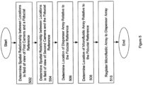
- a method of registering a location of a dispenser array in relation to a microfluidic array is provided.
- a first one of the dispenser array and the microfluidic array is movable in relation to the frame, and the other of the first one of the dispenser array and the microfluidic array is fixed relative to the frame.
- the relative position of the dispenser array is identified by a set of coordinates.
- a first camera is in rigid association with one of the dispenser array and the microfluidic array.
- the method includes identifying a fiducial reference in rigid association with the other one of the dispenser array and the frame, in a manner permitting the fiducial reference to appear in a first position of a field of view of the first camera when the dispenser array is in an alignment position, associated with a first coordinate set, relative to the frame. Quantities related to a vector displacement from the alignment position to a fixed position on the microfluidic array are determined. The quantities thus determined are used to guide positioning of the dispenser array relative to the microfluidic array.
- the first one of the dispenser array and the microfluidic array may be configured to move independently in each of three approximately mutually orthogonal directions.
- the first one of the dispenser array and the microfluidic array may be moved relative to the frame so that a fiducial reference appears in a plurality of distinct additional positions in the field of view of the first camera, each position associated with a distinct coordinate set.
- An orientation of the first camera relative to the directions may be determined based on the plurality of distinct positions.
- a second camera may be mounted in rigid association with the other one of the dispenser array and the microfluidic array.
- a second fiducial reference capable of being viewed by both the first camera and the second camera may be identified.
- the second fiducial reference may be viewed with both the first camera and the second camera to determine quantities of a vector displacement from a position within the field of view of the first camera to a position within the field of view of the second camera.
- the first one of the dispenser array and the microfluidic array may be moved relative to the frame so that a second fiducial reference on the one of the dispenser array and the microfluidic array appears in a plurality of distinct positions in the field of view of the second camera, each position associated with a distinct coordinate set.
- the orientation of the second camera relative to the directions may be determined based on the plurality of distinct positions.
- first camera is in rigid association with the first one of the dispenser array and the microfluidic array, the first camera being rigidly displaced from a fixed position on the first one of the dispenser array and the microfluidic array by a displacement vector.
- the method further includes moving the first one of the dispenser array and the microfluidic array relative to the frame so that the fixed position on the first one of the dispenser array and the microfluidic array is within the field of view of the one of the second camera in rigid association with the frame. Quantities of the displacement vector are determined.
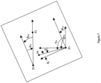
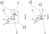
- World Coordinate System having a center of origin is identified.
- a First Camera Coordinate System having a first camera center of origin within a field of view of the first camera is identified.
- a Second Camera Coordinate System having a second camera center of origin within a field of view of the second camera is identified.
- a transformation for transforming a coordinate in the First Camera Coordinate System to the World Coordinate System is determined.
- a second transformation for transforming a coordinate in the Second Camera Coordinate System to the World Coordinate System is determined.
- At least one of the dispenser array and the microfluidic array is rotatable around a center of rotation.
- a position of the center of rotation is determined. Determining the coordinates of the center of rotation may include applying a best fit circle algorithm or another geometric algorithm.
- a method of registering a dispenser array to a microfluidic array rigidly coupled to a frame is presented.
- the dispenser array is movable in relation to the frame.
- a first camera is in rigid association with the dispenser array, and a second camera is in rigid association with the frame.
- a set of coordinates identifies the relative position of the dispenser array.
- the method includes determining a first position of a first fixed point on the microfluidic array relative to a fiducial reference by viewing the microfluidic array with the first camera.
- a second position of a second fixed point on the dispenser array relative to the fiducial reference is determined by viewing the dispenser array with the second camera.
- Quantities of a vector displacement from the first position to the second position are determined. The quantities thus determined are used to guide positioning of the dispenser array relative to the microfluidic array.
- a World Coordinate System having a center of origin is defined.
- a First Camera Coordinate System having a center of origin within a field of view of the first camera is defined.
- a transformation for transforming a coordinate in the First Camera Coordinate System to the World Coordinate System is determined.
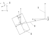
- the World Coordinate System may include a first axis and a second axis orthogonal to the first axis, wherein the dispenser array is capable of moving along a first motion axis and a second motion axis.
- the first motion axis is parallel to the first axis, while the second motion axis defines an angle ⁇ with the second axis.
- the angle ⁇ is determined.
- Calculating the angle ⁇ may include positioning a plate in a field of view of the first camera, the plate having three reticules defining three corners of a triangle and/or rectangle.
- the first camera coordinate system may include a camera first axis and a camera second axis orthogonal to the camera first axis, the camera second axis defining an angle ⁇ C . with the second motion axis of the first camera, the method further comprising calculating the angle ⁇ C .
- Calculating the angle ⁇ C may include viewing a fiducial reticle in the field of view of the first camera; moving the first camera along only the x motion axis; and moving the first camera along only the y motion axis.
- second camera is in rigid association with the frame.
- the method further includes defining a Second Camera Coordinate System having a second camera center of origin within a field of view of the second camera.
- a second transformation for transforming a coordinate in the Second Camera Coordinate System to the World Coordinate System is determined.
- Determining the second transformation may include positioning the dispenser array in the field of view of the second camera, and moving the dispenser array along the x-motion axis. Determining the second transformation may include determining the second camera center of origin in the World Coordinate System. Determining the second camera center of origin in the World Coordinate System may include placing a fiducial in a field of view of the second camera. The fiducial is moved such that the fiducial is in the field of view of the first camera. The coordinates of the fiducial in the First Camera Coordinate System are determined. The coordinates of the fiducial in the First Camera Coordinate System are transformed to the World Coordinate System. The second camera may then be used to determine the coordinates of the dispenser array in the World Coordinate System.
- the dispenser array is rotatable around a center of rotation in rigid association with the first camera.
- the method further includes determining the coordinates of the center of rotation in the World Coordinate System.
- the coordinates of the center of rotation in the World Coordinate System may be determined by rotating the dispenser array and the microfluidic array in a field of view of the second camera and using a best fit circle algorithm or another geometric algorithm.
- a vector between the first camera and the center of rotation may be determined, the vector having coordinates in the World Coordinate System.
- the dispenser array may include a center and define a reference axis.
- the reference axis defines an angle ⁇ RA with an axis of the World Coordinate System.
- the coordinates of the center and the angle ⁇ RA are determined.
- ⁇ RA may be determined by looking at each dispenser of the dispenser array using the second camera.
- the dispensers may approximately form a grid, thus a grid fit algorithm may be used.
- the grid fit algorithm may return the center of the grid as well as the angle of the grid.
- the center of the grid may not be the center of rotation.
- Various algorithms may be in defining the grid fit. One algorithm that may be used minimizes the average amount of error between the real grid and the fitted grid. Another algorithm may minimize the worst case error of any pin on the real grid to the fitted grid.
- the coordinates of the microfluidic array in the World Coordinate System are determined. Determining the coordinates of the microfluidic array in the World Coordinate System may include moving the first camera so as to place the some or all of the microfluidic array field in the field of view of the first camera. For example, the four corners sample wells of the microfluidic array/chip may be viewed to determine where the rectangle of the chip is defined and the rotation of the chip. In various embodiments, the entire microfluidic array/chip may be placed in the field of view of the camera.
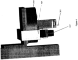
- a system for registering a location of a dispenser array in relation to a microfluidic array includes a first camera in rigid association with one of the microfluidic array and the dispenser array.
- a frame is rigidly coupled to the other one of the microfluidic array and the dispenser array, the one of the microfluidic array and the dispenser movable in relation to the frame.
- a second camera is in rigid association with the frame, the second camera capable of viewing the first camera and the one of the microfluidic array and the dispenser array.
- a controller may control relative motion between the microfluidic array and the dispenser array.
- the controller may include at least one encoder and/or an interface to the first camera for transferring data signals.
- a rotary stage may rotate one of the microfluidic array and the dispenser array.
- a gantry may be used to control motion of the dispenser array relative to the microfluidic array, for example, in three approximately mutually orthogonal directions.
- a method of aligning a first array to a second array is provided.
- Each element within the first array has an expected position relative to other elements in the first array.
- the expected positions of each element in the first array form a template, wherein one or more elements of the first array deviate from their expected position.
- the method includes aligning the template with the first array.
- the template is used to approximate locations of each element in the first array. Elements of the first array are aligned with elements the second array as a function of the approximate locations.
- aligning the template with the first array includes aligning at least one position on the template with at least one position on the first array.
- a camera may be used to determine the location of the at least one position on the first array. Using the camera may include viewing segments of the first array to determine the location. Alternatively, the entire first array may be viewed simultaneously.
- one of the first array and the second array may include receptacles, and the other of the first array and the second array includes pins.
- the pins may have a pin diameter, and each receptacle may define an opening having a diameter that is larger than the pin diameter by a predefined value.
- the pins may be cone shaped.
- Each of the pins may be capable of limited movement.
- the receptacles may have walls defining a beveled opening.
- the receptacles may be through-holes, the method further including viewing the pins through the through-holes using a camera.
- each element within the second array has an expected position relative to other elements in the second array, the expected positions of each element in the second array forming a second template, wherein one or more elements of the second array deviate from their expected position.
- the method further includes aligning the second template with the second array.
- the template is used to approximate locations of each element in the second array.
- Elements of the first array are aligned with the second array as a function of the approximate locations of each element in the second array.
- the first template may be substantially equivalent to the second template.
- a method of dispensing a microfluidic sample includes providing an array of dispensers for dispensing the microfluidic sample, and an array of receptacles, each receptacle capable of receiving microfluidic sample from one of the dispensers. At least one of the array of dispensers and the array of receptacles is scanned with a camera for a fiducial reference. The array of dispensers is aligned with the array of receptacles as a function of the fiducial reference such that transfer of sample from the array of dispensers to the array of receptacles is enabled.
- each dispenser and/or receptacle has an expected position relative to other dispensers in the dispenser and/or receptacle array.
- the expected positions of each dispenser and/or receptacle in the dispenser and/or receptacle array forming a template, wherein one or more of the dispensers and/or receptacles deviate from their expected position.
- the method further includes aligning the template with the dispenser and/or receptacle array based on the fiducial position.
- the template is used to approximate locations of each element in the dispenser and/or receptacle array.
- the elements of the dispenser array are aligned with the receptacle array as a function of the approximate locations.
- scanning includes using the camera to view segments of at least one at least one of the array of dispensers and the array of receptacles to determine the fiducial position.
- the camera may simultaneously view the entire at least one of the array of dispensers and the array of receptacles to determine the fiducial position.
- the array of dispensers may be an array of transfer pins for transferring a plurality of samples to a corresponding plurality of the receptacles.
- the pins may be cone shaped. Each of the pins may be individually capable of limited movement.
- the receptacles may have walls defining a beveled opening.
- the array of receptacles may be a platen array of through-hole wells.
- the dispensers may be viewed through the through-hole wells using the camera.
- the array of receptacles may be a platen array of closed-ended wells. At least one of the receptacles may include hydrophilic walls that attract the sample. At least one of the receptacles may include an opening surrounded by hydrophobic material.
- a system for dispensing sample fluid includes one or more dispensers forming a dispenser array. At least one receptacle array includes one or more receptacles; each receptacle capable of receiving sample fluid from one of the dispensers. An alignment means aligns the dispenser array and the at least one receptacle array.
- the alignment means includes a rotational stage for rotating at least one of the dispenser array and the at least one receptacle array.
- the alignment means may include a vision means for viewing one at least one of the dispenser array and the at least one receptacle array.
- the vision means includes one or more sensors for detecting position of at least one of the dispenser array and the receptacle array, which may be one of a optic sensor and an acoustic sensor.
- the vision means may be a camera.
- One of the dispenser array and the receptacle array may include a fiducial reference, the vision means capable of viewing the fiducial reference to align the dispenser array and the at least one receptacle array.
- the at least one receptacle array may be one of a platen and a biochip.
- the receptacle array may be a microfluidic array.
- the receptacles may include closed and/or through-hole wells.
- the at least one receptacle array may include a plurality of receptacle arrays positioned in a tray.
- the dispenser array may be an array of transfer pins for transferring a plurality of samples to a corresponding plurality of the receptacles.
- the pins may be cone shaped and/or individually capable of limited movement.
- the receptacles may have walls defining a beveled opening.
- the at least one of the receptacles may include hydrophilic walls that attract the sample.
- the at least one of the receptacles may include an opening surrounded by hydrophobic material.
- each element within the dispenser array may have an expected position relative to other elements in the dispenser array, the expected positions of each element in the dispenser array forming a template, wherein one or more elements of the first array deviate from their expected position.
- the alignment means may include template means for aligning the template with the dispenser array; approximating locations of each element in the dispenser array using the template; and aligning elements of the first array with the second array as a function of the approximate locations.
- the embodiments relate to differentially coated plates, methods for preparing said plates, and methods for using the differentially coated plates for conducting a plurality of specified reactions.
- some embodiments provide a process for differentially treating surfaces of a substrate, such as channel substrate or a through-hole array plate, wherein the different surfaces are subjected to a series of processes and reactions which result in differential surface coatings for the etched or through-hole surface and the surface of the substrate or plate.
- a differential coating is a coating or process whereby the coating physicochemical properties vary in a controlled manner, and in a controlled pattern. These coating properties can be surface tension, reactivity, biocompatibility, and numerous other properties.
- the inside of the through-holes is preferably hydrophilic and biocompatible, whereas the outside surface of the plate is preferably hydrophobic and non-protein binding, although it is envisioned that properties for the inside surface relative to the outside surface may change, as needed.
- a chip When an OpenArray TM chip is differentially coated such that the through-holes are hydrophilic and the exterior of the chip is hydrophobic, a chip may be dipped into a high surface tension fluid such as water, and when removed, the individual through-holes are filled with fluid and the exterior of the chip is dry.
- a high surface tension fluid such as water
- the following provides generalized methods and devices for spatially controlling the surface modifications of an etched surface and is a focus of this invention.
- One important aspect of the invention is the ability to force load liquids into the OpenArray TM for exchanging fluids that enable the differential coating process.
- the OpenArray TM chips become uniformly hydrophobic.
- When loading is attempted to perform chemistry in the through-holes to affect differential coating a high surface tension fluid will not load the through-holes, and a low surface tension fluid will wet the entire chip. It becomes difficult to perform differential coating a simple way. Therefore, the novel technique of forced loading was invented.
- the uniformly hydrophobic chip is submerged in a low surface tension co-solvent, such as ethanol.
- the chip is submerged in a high surface tension fluid that contains reagents for the differential chemistry.
- the high surface tension fluid exchanges and replaces the low surface tension fluid in the wells.
- the chip is removed from the high tension fluid, the high surface tension fluid sheets off the exterior coating of the chip, but remains in the through-holes.
- the chip can then be submerged in an immiscible fluid such as silicone oil or a perfluorinated hydrocarbon. This keeps the high surface tension fluid in the wells while the chemistry or deposition occurs, without evaporation or leakage of the high surface tension fluid onto the exterior of the chip.
- This process can be generalized beyond hydrophilic interior and hydrophobic exterior coatings to, for example, reverse surface tensions of the liquids relative to the platen substrate to make the interior surface hydrophobic and the exterior surface hydrophilic. This would be useful in loading polar solvents, such as benzene, into the OpenArray channels for non-biological chemistry applications.
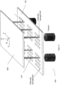
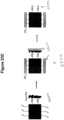
- Deposition of one material e.g. hydrophobic coating
- N 2 non-reactive gas
- Second material is loaded, if needed, as a liquid into the channels to react and chemically or physically modify and coat the interior surface.
- the second material does not wet nor react with the first material to change its physicochemical properties.
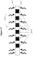
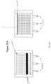
- Uniform deposition of one material e.g. hydrophobic coating
- Second material deposited with process gas or liquid on interior of through-holes. UV light may/may not be used to initiate chemical reaction for deposition/chemical modification of interior surfaces.
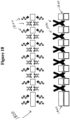
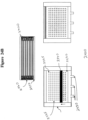
- Uniform deposition of one material e.g. hydrophobic coating
- Subsequent stripping of coating from the through-holes by forced loading of an etching solution that physiochemically removes the first material from the interior surfaces of the channels.
- Second material for coating/modifying interior surfaces is applied by liquid or gas deposition.
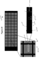
- a uniformly treated chip e.g. hydrophobically
- a dispenser such as a pin, a syringe tip, a piezo dispenser, etc.
- an etchant or other liquid that reacts with the first material to product a surface with the desired properties (e.g. hydrophilic).
- the patterned substrate may be a stainless steel plate having etched grooves or patterns, or a stainless steel plate having through-holes such as a microfluidic sample array (a chip).
- the patterned substrate may be of silicon or glass.
- Various methods of differentially treating the patterned substrate or through-hole array plate may include a series of treatments and reactions.
- the series of treatments in various embodiments in accordance with the presently claimed invention may involve inspection; labeling for tracking during processing; cleaning; uniform coating of the planar non-etched or non-holed substrate surface with a first reagent; treating the etched surface or through-hole surface with a reagent that activates the etched surface or through-hole surface for later treatment by producing reactive groups on the etched or through-hole surfaces; treating the etched or through-hole surfaces with a reagent different from that used to treat the planar non-etched or non-holed surface of the substrate; additional treatment of the etched or through-hole surface to prevent reaction with reagents which may be used in later treatments; coating the planar non-etched or non-holed surface of the substrate with a second reagent that either adsorbs or chemically reacts with the first reagent on the non-etched or non-holed surface; and quality control tests.
- a particular embodiment may first uniformly coat all surfaces of the substrate by treating with vinyl-terminated silane, for example, then selectively oxidize the etched or through-hole surfaces by force loading with ethanol a permanganate solution, for example, of 5 mM KMnO 4 and 19.5 mM NaIO 4 in deionized water followed by incubation in a nonreactive oil or liquid such as a perfluorinated alkane solution for 2 hours, then PEGylation (covering with polyethylene glycol or molecules bearing PEG moieties) of the selectively oxidized etched or through-hole surface is done followed by re-loading of the etched or through-holed surface with additional PEG, with a final coating of the non-etched or non-holed surface accomplished by treatment with perfluorosilane using vapor-phase deposition.
- a permanganate solution for example, of 5 mM KMnO 4 and 19.5 mM NaIO 4 in deionized water followed by incubation in a nonre
- the initial coating of all surfacesof the substrate may be done using liquid phase vinyl deposition with 7-octenyltrichlorosilane or 10-undecenyltrichlorosilane, for example.
- the PEGylation may alternatively be performed using various PEG-silane derivatives, such as methoxy-PEG silane MW 2000, methoxy-PEG silane MW 500, and methoxy-PEG silane MW 10,000.
- triethoxysilylbuteraldehyde may be used as an alternative first coating of the non-etched or non-holed planar surface of the substrate. This allows PEGylation of the etched or through-hole surface without selective oxidation.
- PEGylation methods include the use of longer PEG molecules, such as methoxy-PEG-amine MW 5000 in place of silane-PEG coatings of lower molecular weights.
- PEG within the PEGylated etched or through-hole surfaces may be cross-linked using hyperbranched PEG and PEI molecules and appropriate cross-linker molecules.
- the etched or through-hole surface is treated with a reagent to expose functional group A, followed by exposure to a solution containing a PEG having a terminal functional group B that is reactive with functional group A.
- the OpenArray could be coated with different materials catalyzed by absorption of radiant energy (UV, X-ray, electron beam) at different locations in the array by one or more of the previously described embodiments and then by use of one or more masks, different materials could be formed in different regions of the OpenArray by exposure to radiation for specified durations, intensities and energies (e.g. UV, X-ray, electron beam).
- the radiation could be focused and directed to specified locations by a number of focusing means including lenses.
- the focused beam photons or electrons
- the optical based method can be combined with one or more of the previous embodiments for applying a differential coating to an OpenArray.
- inventions provide a method for differentially coating a substrate having at least one exterior surface and a plurality of channels for liquid disposed therein, each channel having at least one interior surface in communication with at least one exterior surface, the method comprising applying a first coating agent to the substrate to create a coated substrate and selectively modifying at least one exterior surface or at least one interior surface of the coated substrate with a first modifying agent to create at least one modified surface having a first specified physicochemical property and a non-modified surface such that the modified surface differs from the non-modified surface with respect to the first specified physicochemical property.
- a second modifying agent is applied to the first modified surface such that the second modifying agent imparts a second specified physicochemical property to the modified surface.
- the first modifying agent may be applied in a mixture of two or more modifying agents having distinct specified physicochemical properties, to create at least one modified surface having a mixture of distinct specified physicochemical properties.
- the modified surface may be a modified gradient surface having a gradient mixture of the distinct specified physicochemical properties, or the modified surface may be a modified mixed-layer surface having a heterogeneous mixture of distinct specified physicochemical properties.
- a third or more modifying agent may be applied to the modified agent to impart a third or more specified physicochemical property to the modified surface.
- Other related embodiments provide a variation of the described method wherein the at least one modified surface has one or more of the first, second and third specified physicochemical properties or it may have a combination of the specified physicochemical properties.
- modifying agent is applied uniformly to create at least one uniformly modified surface, or applied non-uniformly such that the non-uniformly modified surface is non-uniform with respect to a property selected from the group consisting of concentration of modification, thickness of modification, continuity of modification, presence of the specified physicochemical property, and nature of the specified physicochemical property.
- Selectively modifying further comprises selectively activating at least one interior surface or at least one exterior surface with an activating agent prior to selectively modifying said surface so as to create at least one activated surface and modifying the at least one activated surface by reacting the surface with the modifying agent to create at least one modified surface with the first specified physicochemical property.
- the exterior or the interior surface is modified.
- the method further comprises causing a blocking agent to adhere to at least one interior surface or at least one exterior surface prior to selectively applying the first coating agent so as to create at least one blocked surface, and removing the blocking agent from the blocked surface after applying the first coating agent.
- the blocked surface may either be at least one exterior surface, or at least on interior surface.
- the method further comprises causing a blocking agent to adhere to at least one modified surface to create at least one blocked modified surface, applying a second coating agent to the substrate and removing the blocking agent from the blocked modified surface.
- the modified surface may be an exterior surface or an internal surface and the channels may be through-holes, passages or troughs.
- the physical interactions between the blocking agent and the surface are selected from one or more of the group consisting of Van der Waal's forces, hydrogen bonding interactions, hydrophilic interactions, hydrophobic interactions, dipole-dipole interactions, ionic interactions, surface tension interactions, and polar interactions.
- the coating agent or agents, blocking agents, and/or first and later modifying agents adhere to the exterior or interior surface by chemical bonding such as covalent bonding, coordinate covalent bonding, or ionic bonding.
- Still other embodiments provide a method for differentially coating a surface wherein the first, second and other modifying agents are selected from the group consisting of a polymer, a monomer, a cross-linking agent, a photo-cleavable agent, a silane, a lipid, a fatty acid, an amino acid, a peptide, a protein, an antibody, an enzyme, a surfactant, a micelle, a liposome, a nucleotide, an oligonucleotide, a nucleic acid, a salt, a wax, a low-melting solid, and an oil.
- the first, second and other modifying agents are selected from the group consisting of a polymer, a monomer, a cross-linking agent, a photo-cleavable agent, a silane, a lipid, a fatty acid, an amino acid, a peptide, a protein, an antibody, an enzyme, a surfactant, a micelle,
- the first and second coating agents may also be selected from the group consisting of a polymer, a monomer, a cross-linking agent, a photo-cleavable agent, a silane, a lipid, a fatty acid, an amino acid, a peptide, a protein, an antibody, an enzyme, a surfactant, a micelle, a liposome, a nucleotide, an oligonucleotide, a nucleic acid, a salt, a wax, a low-melting solid, and an oil.
- a polymer a monomer, a cross-linking agent, a photo-cleavable agent, a silane, a lipid, a fatty acid, an amino acid, a peptide, a protein, an antibody, an enzyme, a surfactant, a micelle, a liposome, a nucleotide, an oligonucleotide, a nucleic acid, a salt,
- the blocking agent may be selected form the group consisting of a polymer, a monomer, a cross-linking agent, a photo-cleavable agent, a silane, a lipid, a fatty acid, an amino acid, a peptide, a protein, an antibody, an enzyme, a surfactant, a micelle, a liposome, a nucleotide, an oligonucleotide, a nucleic acid, a salt, a wax, a low-melting solid, and an oil.
- Selectively modifying a surface may further comprise applying a solvent having a lower surface energy than that of the modifying agent to the at least one exterior surface or the at least one interior surface prior to applying the modifying agent, or selectively modifying may further comprise subjecting the substrate to a pressure differential prior to applying the modifying agent or by subjecting the substrate to a liquid stream of modifying agent such that momentum from the liquid stream applies the modifying agent to the at least one interior surface.
- selectively modifying further comprises applying the modifying agent by exposing at least one exterior surface to a reactive vapor while subjecting at least one interior surface to a laminar flow stream of non-reactive gas such that the gas stream prevents the reactive vapor molecules from interacting with that interior surface.
- the activator if used, as an oxidizing agent, a cross-linking agent, or an energy source, may be a solid of a liquid such that the blocking agent makes at least one blocked surface any one or more of impermeable to electrons; impermeable to ionizing radiation; or unavailable for or resistant to further chemical reaction, light-activated reaction, or chemical modification.
- the blocking agent is selected from the group consisting of a polymer, a monomer, a cross-linking agent, a photo-cleavable agent, a silane, a lipid, a fatty acid, an amino acid, a peptide, a protein, an antibody, an enzyme, a surfactant, a micelle, a liposome, a nucleotide, an oligonucleotide, a nucleic acid, a salt, a wax, a low-melting solid, and an oil.
- a method for differentially coating a substrate having at least one exterior surface and a plurality of channels for liquid disposed therein, each channel having at least one interior surface in communication with at least one exterior surface comprising applying a first coating agent to the substrate to create a coated substrate, blocking at least one exterior surface or at least one interior surface of the coated substrate to create at least one blocked surface and at least one non-blocked surface, selectively modifying the non-blocked surface with a modifying agent to create at least one modified surface and at least one non-modified surface such that the modified surface differs from the non-modified surface with respect to a specified physicochemical property, and unblocking the at least one blocked surface.
- the blocked surface may be an exterior surface or an interior surface
- selectively modifying comprises exposing the at least one non-blocked surface to UV radiation, ionizing radiation, an ion-beam, an electron beam, microwave radiation, visible light, a coherent light source, or a laser such that the specified physicochemical property is achieved.
- selectively modifying comprises treating the at least one non-blocked surface with an etching material that removes the coating material from the non-blocked surface.
- applying the first coating agent comprises uniformly or non-uniformly applying the coating agent, such that the first coating agent is one or more of a hydrophobic agent, a hydrophilic agent or a multifunctional agent and the specified physicochemical property of the at least one modified surface is a hydrophobic property or a hydrophilic property.
- applying the second coating agent comprises uniformly or non-uniformly applying the coating agent and the second coating agent may be one or more of a hydrophobic agent, a hydrophilic agent or a multifunctional agent wherein the specified physicochemical property of the at least one modified surface is a hydrophobic property or a hydrophilic property.
- Another particular examples provides a differentially coated device for conducting a plurality of nano-volume specified reactions, the device comprising a platen having at least one exterior surface modified to a specified physicochemical property, a plurality of nano-volume channels, each nano-volume channel having at least one interior surface in communication with the at least one exterior surface, wherein the at least one interior surface of one or more of the of nano-volume channels is selectively coated with an optionally dissolvable coating agent physisorbed to the at least one interior surface, wherein the optionally dissolvable coating agent comprises a coating agent and a first component for the plurality of specified reactions.
- the coating agent is selected from the group consisting of a low melting-point solid; a hydratable solid, semi-solid or gel, a polymer, a block co-polymer, a polyethylene glycol, a polyvinyl alcohol, a polyethyleneimine, a lipid, a surfactant, a controlled-release agent, and a salt.
- a method for preparing a differentially coated device comprises providing a device having a plurality of nano-volume channels for retaining one or more reaction components for the specified reactions, each channel having at least one interior surface in communication with at least one exterior surface, selectively coating at least one interior surface of one or more of the plurality of channels with a dissolvable coating agent so as to prepare the differentially coated device, wherein the dissolvable coating agent is physisorbed to the at least one interior surface and comprises a coating agent and a first component for the plurality of specified reactions.
- Other examples provide a method for preparing a differentially coated device as described above, wherein providing further comprises selectively coating at least one external surface with a coating agent to impart a specified physicochemical property, using an autoloader device comprising a loading chamber sufficiently large to contain the device to be coated, the coating reagent, and an immiscible fluid that lifts the coating reagent over the device as the volume of the immiscible fluid is increased.
- the coating agent is selected from the group consisting of a low melting-point solid; a hydratable solid, semi-solid or gel; a polymer; a block co-polymer; a polyethylene glycol; a polyvinyl alcohol; a polyethyleneimine; a lipid; a surfactant; a controlled-release agent; and a salt
- loading further comprises using a pin-loading device comprising an array of calibrated transfer pin dispensers to load the plurality of channels with one or more reaction mixtures, or using a piezoelectric disperser to load the channels.
- a method for conducting a plurality of specified reactions using the differentially coated device of above comprising loading the plurality of channels in the differentially coated device with one or more reaction mixtures comprising additional components sufficient for the plurality of specified reactions, and initiating the plurality of reactions by one or more methods selected from the group consisting of heating the device, exposing the device to photo/optical conditions, hydrating the nano-volume channels; and stacking the device with one or more other devices to mix components in each device upon contact, thus initiating the specified reactions.
- a more particular example not forming part of the invention provides a method for conducting a plurality of nano-volume specified reactions as described, wherein loading further comprises using a pin-loading device comprising an array of calibrated transfer pin dispensers to load the plurality of channels with one or more reaction mixtures, or using a piezoelectric disperser to load the channels.
- a plurality of channels that may vary from channel to channel with respect to any or all of: a specified reaction, a sample, a specified physicochemical property of the nano-volume channel, and method of initiating a specified reaction, wherein the plurality of channels comprise a plurality of nano-volume through-holes or nano-volume troughs and wherein the plurality of specified reactions comprise different specified reactions in two or more of the plurality of channels.
- the plurality of specified reactions may comprise the same specified reaction in two or more of the plurality of channels, and may comprise maintenance of cell cultures.
- Another particular example not forming part of the invention provides a method for preparing a differentially coated device for conducting a plurality of nano-volume specified reactions, the method comprising providing a device having a plurality of channels for retaining one or more reaction components for the specified reactions, each channel having at least one interior surface in communication with at least one exterior surface, selectively coating at least one interior surface of the plurality of channels with a dissolvable coating agent so as to prepare the differentially coated device, or wherein the dissolvable coating agent is physisorbed to the at least one interior surface and comprises a coating agent and optionally a first component for the plurality of specified reactions.
- selectively coating further comprises using a pin-loading device comprising an array of calibrated transfer pin dispensers to selectively physisorb the dissolvable coating agent to the at least one interior surface.
- the loading device may be piezoelectric disperser.
- Still another example not forming part of the invention provides a method for conducting a plurality of nano-volume specified reactions using a first and at least second differentially coated device prepared described above, the method comprising loading the plurality of channels in the first differentially coated device with one or more samples, wherein the samples are the same or different, initiating the plurality of reactions by stacking the first device with at least a second differentially coated device loaded with a mixture of reagents comprising sufficient components common to the specified reactions, such that upon stacking, the mixture of reagents in the at least second device mixes with the samples of the first device, thereby initiating the specified reactions.
- loading further comprises using a pin-loading device comprising an array of calibrated transfer pin dispensers to load the plurality of nano-volume channels with one or more samples, or loading further comprises using a piezoelectric disperser to load the channels.
- Still another more particular example not forming part of the invention provides a method for preparing a differentially coated device for conducting a plurality of nano-volume specified reactions, the method comprising preparing a platen having a prescribed spatial arrangement of micro-volume channels, each micro-volume channel having at least one interior surface in communication with at least one exterior surface, wherein preparing further comprises coating a flexible printing pad with a coating agent, wherein the coating agent is applied to the exterior surface to create a spatially arranged coating on the printing pad which correlates to the prescribed spatial arrangement for the channels, transferring the spatially arranged coating on the flexible printing pad to the platen by contacting at least one external surface of the platen with the printing pad to impart the prescribed spatial arrangement of micro-volume channels to the platen,and selectively coating the at least one interior surface of one or more of the plurality of micro-volume channels with a coating agent so as to prepare the differentially coated device, wherein the coating agent is physisorbed to the at least one interior surface and comprises a coating agent and optionally a first component for
- Physical Property means any property involving the principles of physics and chemistry, alone or in combination, including but not limited to any property of a substance, reaction, molecule, event, process relating to physical state, electronic structure, electronic principles, thermodynamic principles, atomic structure, atomic principles, molecular composition and geometry, chemical composition, chemical reactivity, valence state, oxidation state, oxidation potential, reduction potential, molecular structure, molecular composition, molecular principles, aromaticity, spatial orientation, isomeric form, stereochemical orientation, surface tension, refractive index, wetability, water solubility, density, melting point, boiling point, conductivity, and absorption, luminescence, emission and reflection properties and other light/energy related properties defined by wavelength phenomenon, for example, color and color changes.
- physicochemical properties include but are not limited to those relating to hydrophobicity, lipophilicity, hydrophilicity, protein sequence, intramolecular interactions, intermolecular interactions, two- and three-dimensional structure, for example protein primary, secondary and tertiary structure, nucleic acid sequence and structure, antibody structure, enzyme structure, morphology, properties relating to protein-protein interactions, protein-small molecule interactions, nucleic acid-nucleic acid, nucleic acid-protein, or nucleic acid-small molecule interactions, antibody-antigen interactions.
- the term also encompasses the idea of an intermediate property that is capable of being altered.
- Channel as used herein means a space defined by an interior surface or surfaces connecting at least one exterior surface, wherein the channel is capable of confining a liquid, or in which liquid flows, diffuses, or resides.
- Channels may be through-holes, troughs, passages, etched grooves, contract-printed prescribed alignment patterns, wherein the alignment is aligned or random in space, interconnected with other channels or not.
- Three-hole as used herein means a cylindrical or other shaped channel open at two ends, so that liquid can flow through. It is often referred to as a microwell, a channel, or micro-volume sample chamber. The volume is such that it may be less than 1 ⁇ L, or less than 400 nL, or as little as several nL. Liquid sample is placed therein, and held by surface tension, aided by the nature of the differential coating on the external surface with which the through-hole is in communication.
- a nano-volume channel, or sample holder may be similarly sized, by volume, as a micro-volume channel, through-hole or sample chamber, though typically a nano-volume channel or through-hole has a smaller capacity for a liquid sample than a micro-volume channel/through-hole.
- Trough as used herein means a particular type of channel having a concave interior surface defining two continuous sides and a bottom but open on the third side, the two sides in communication with an exterior surface.
- Hydrophilic as used herein means that which has an affinity for water, of absorbing water, mixing with water, dissolving in water, and interacting with water such as through hydrogen bonding.
- Hydrophilic materials and compounds may be completely hydrophilic, or have regions of hydrophilicity, such as a protein, or lipid bi-layer component like a fatty acid. Hydrophilic materials tend to have ionic or charged regions, or are polar.
- a hydrophilic molecule or portion of a molecule is one that typically is electrically polarized and capable of hydrogen bonding, enabling it to dissolve more readily in water than in oil or other "non-polar" solvents. Hydrophilic molecules can establish hydrogen bonds with water molecules, which are favorable by thermodynamics and makes these molecules soluble in water.
- Hydrophobic as used herein means that which has an aversion for water. Hydrophobic compounds and materials tend to be electrically neutral and nonpolar, and thus prefer other neutral and nonpolar solvents or molecular environments. Hydrophobic is often used interchangeably with “oily” or “lipophilic” or “oleophilic.” Hydrophobic refers to the physical property of a molecule that is repelled by water. Hydrophobic molecules in water often cluster together to minimize thermodynamically unfavorable interfaces or interactions with the polar water molecules.
- Lipophilic as used herein means that which has an affinity for lipids. Lipophilic is a particular concept within the broad concept of hydrophobic - i.e. materials which avoid water - but more particularly refers to those materials which have an affinity for compounds commonly referred to or known as lipids, such as molecules with a long-chain saturated or unsaturated hydrocarbons tail and a polar, or charged oxygen-containing head. More generally, a lipid may be thought of as a greasy hydrophobic compound containing carbon, hydrogen and oxygen. Examples of lipids include steroids; phospholipids, neutral fats and carotenoids and sphingolipids.
- Blocking Agent means a material or substance used to physically block access of a surface, defined space, channel, region of a surface or regions of a surface or surfaces, from exposure to a chemical composition, reagent or process, energy source or exposure, or environment.
- a blocking agent may be a solid, including a low-melting point solid such as a wax or polymer, or a salt that may or may not be applied in liquid form and then dried; or the blocking agent may be a liquid, such as an oil, or a grease.
- blocking agents include traditional chemistry blocking agents, wherein a functional moiety on a particular chemical composition is reacted with a standard reagent known in the field to create a modified moiety that is "blocked" or protected from reacting with a later reagent in a particular reaction scheme.
- the blocking agents are removed after protecting the particular region, or moiety from the chemical reagent of process, energy source or exposure
- Modifying Agent as used herein means a material or reagent that is capable of modifying a surface, a composition, a structure, a physicochemical property or particular characteristic, by either chemical means, such as a chemical reaction, or physical means, such as blocking. Modifying agents may be blocking agents, and blocking agents may be modifying agents. Both may be coating agents.
- Coating Agent as used herein means "a material which may be applied to a surface to physically cover all or part of the surface.
- a coating agent may be homogenous in its chemical composition and/or chemical properties, physical composition and/or physical properties, or it may be heterogeneous, such as a gradient coating, a multifunctional, multicompositional or multilayered coating.
- a coating may be applied chemically, wherein the coating adheres to the coated surface through chemical bonds, such as covalent bonds, or it may be applied as a physical coating, wherein the coating adheres to the coated surface through physical interactions such as electrostatic forces, hydrogen bonds, surface tension, Van der Waal's forces, polar interactions and dipole forces, for example..
- Uniform coating as used herein means a coating, layer, surface composition or deposition covering a surface that is homogeneous relative to chemical, molecular, or physical state or properties, although the thickness and nature of the coating may vary at any given location on the surface relative to another location.
- a non-uniform coating is a coating, layer, surface composition or deposition covering a surface that is heterogeneous relative to chemical, molecule or physical state or properties, and may also vary in thickness and surface appearance from one region of the coated surface to another.
- Nano-volume specified reaction as used herein means a particular reaction run in a nanoliter volume scale, such that the total reaction volume is generally less than a microliter.
- Dissolvable as used herein means a material, compound, substance or agent whose physical state can be change through heat, hydration, salvation, or other means at will.
- a dissolvable substance may be a wax, which melts to a liquid upon treatment with heat, or a salt or powder which dissolves upon addition of water or other liquid.
- Physicalbed as used herein means that the forces holding a substance to a surface do not involve the making or breaking of chemical bonds, but rely on purely physical interactions for adherence, absorption, affinity or similar interactive phenomena.
- a system and method for registering a location of a dispenser array relative to a receptacle array is presented.
- the receptacle array which may be a microfluidic array, is rigidly coupled to a frame, while the dispenser array is movable in relation to the frame.
- a first camera is in rigid association with one of the dispenser array and the frame. The first camera is capable of viewing a fiducial reference in rigid association with the other of the dispenser array and the frame when the dispenser array is in an alignment position.
- Quantities related to a vector displacement from the alignment position to a fixed position on the microfluidic array are determined. The quantities thus determined are used to guide positioning of the dispenser array relative to the microfluidic array. Details are discussed below.
- Fig. 3 shows a system 300 for registering a dispenser array 301 to a receptacle array, which may be, without limitation, a microfluidic array 303, in accordance with one embodiment of the invention.
- the dispenser array 301 typically includes one or more fluid dispensing elements at expected positions in a plane.
- the dispenser array 301 may be, without limitation, an array of transfer pins capable of being loaded with transfer liquid.
- the microfluidic array 303 may be a platen or chip with a plurality of closed and/or through-hole sample wells at expected positions, as described above.
- the microfluidic array 303 is rigidly coupled to a frame 305, while the dispenser array 301 is movable in relation to the frame 305.
- the dispenser array 301 may be rigidly coupled to the frame 305, with the microfluidic array 303 movable in relation to the frame 305.
- the dispenser array 301 is, without limitation, capable of moving independently in approximately three mutually orthogonal directions.
- the three directions will be referred to as an x-motion axis 307, a y-motion axis 309, and a z-motion axis 311.
- a gantry with two parallel tracks 313 and 315 may be attached to the frame 305 to assist in moving the dispenser array 301. Due to various tolerances, there is typically skew from orthogonality between the directions, such as between the x-motion axis 307 and the y-motion axis 309.
- a controller 325 may be used to control motion of the dispenser array 301 relative to the frame 305.
- Controller 325 may include, without limitation, a robotic motion control system, various circuitry, and/or a Central Processor Unit (CPU) that may include memory and be appropriately pre-programmed or configured to be loaded with an appropriate program.
- Memory may include, for example, a diskette, a fixed disk, a Compact Disk (CD), Read Only Memory (ROM), Erasable Programmable Read-Only Memory (EPROM), and/or Random Access Memory (RAM).
- the controller 325 may further include one or more encoders that precisely determine relative position of the dispenser array 301.
- an encoder for each motion-axis 307, 309, 311 may be provided, such that a set of coordinates identifies the relative position of the dispenser array 301.
- the system 300 includes one or more vision means for viewing either or both the dispenser array 301 and the microfluidic array 303.
- the vision means may include, for example, one or more sensors for detecting position of either or both the dispenser array 301 and the microfluidic array 303.
- the sensor may be, without limitation, an optical or acoustic sensor.
- the vision means includes a first camera 317 in rigid association with the dispenser array 301.
- the dispenser array 301 may be capable of rotating about a fixed point relative to the first camera 317.
- the dispenser array 301 may be mounted to a rotary stage 319 via a dispenser holder 321.
- the rotary stage 319 permits controlled rotation of the dispenser array 301 about a center of origin 401, the center of origin 401 being in rigid association with the dispenser array 301.
- An alternative design may rotate the microfluidic array 303 instead of, or in combination with, the dispenser array 301.
- a second camera 321 may be used, among other things, to determine the orientation of the dispenser array 301 relative to the camera 317.
- the second camera 321 may be, without limitation, rigidly mounted to the frame 305.
- a World Coordinate System may be defined whose position is fixed relative to, for example, the frame 305, and to which other elements in the system 300 will be referenced.
- the Origin of the WCS (O W ) may be, without limitation, defined by a fixed fiducial on the frame 305. Relationships between the WCS, the field of view of the first camera 317 defined by a First Camera Coordinate System (FCCS), the field of view of the second camera 321 defined by a Second Camera Coordinate System (SCCS), the position of dispenser array 301, and/or the position of the microfluidic array 303 are determined.
- FCCS First Camera Coordinate System
- SCCS Second Camera Coordinate System
- Each of the various coordinate systems may be, without limitation, a Cartesian coordinate system following the right hand rule, however other coordinate systems known in the art may be used.
- the x-motion axis 307 of the first camera 317/dispenser array 301 may be defined to be parallel to the x axis of the WCS, while the y-motion axis 309 of the dispenser array 301 is not guaranteed to be parallel to the y axis of the WCS.
- the angle between y-motion axis 309 and the y axis of the WCS, ⁇ , is assumed to be fixed after the gantry is initialized.
- Fig. 5 shows an illustrative process of registering the dispenser array 301 to the microfluidic array 303.
- the process begins at step 502, in which a spatial relationship between a location in the field of view of the First Camera 317 and a fiducial reference is determined.
- the fiducial reference will be defined as the origin (O W ) of the WCS.
- FCCS may be defined, for example, such that the origin of the FCCS, O F , is the center of the first camera's field of view.
- the x and y axis of the FCCS makes an angle with respect to the x and y axis of the WCS, which is determined.
- the pixel resolution of the First Camera with respect to the WCS, and a transformation between positions in the FCCS and the WCS, are determined.
- Fig. 6 shows the relative positions of the WCS 601, the FCCS 603 and the dispenser array 605.
- the first camera 317 cannot be mounted so that the y-axis 607 of the FCCS perfectly corresponds to the y-motion axis 309, but rather the y-axis of the FCCS makes an angle ⁇ C to the y-motion axis 309. Accordingly, the angle the first camera 317 makes with respect to the WCS is ⁇ C + ⁇ . These two angles must be decoupled because ⁇ may change when the motion axes 307 and 309 are initialized.
- the first camera 317 may moved such that a fiducial reference (which may be fixedly positioned, without limitation, to the frame 305) appears in a plurality of distinct positions in the field of view of the first camera, as shown in Fig. 7 . More particularly, the fiducial reference may be placed on the right side of the first camera's 317 field of view. The position P 1 of the fiducial is recorded in both the WCS and the FCCS. A move along only the x-motion axis 307 will then be made such that the fiducial moves to the left side of the first camera's 317 field of view. The fiducial will be searched here and this point P 2 will be saved in both coordinate systems as before. The angle made by the two points can be determined as follows:
- the first camera 317 will be moved along only the y-motion axis 309 in the positive direction from point 3 to point 4.
- the angles made by these two point can be determined as follows:
- a plate with three accurately known points PR1, PR2, and PR3 may be used to determine ⁇ .
- the points PR1, PR2, and PR3 may form, for example, three corners of a square, the square having sides with known length L.
- the plate may be attached to the frame 305 such that the two sides of the square defined by points PR1 and PR2, and PR1 and PR3 are aligned as close as possible to the WCS y and x axis, respectively.
- the two end points PR1 and PR3 of the side that is substantially parallel to the x-axis of the WCS are searched for using the first camera 317. As the end points are searched, the angle, ⁇ CX , determined earlier will be used to transform the two end points PR1 and PR3 to the WCS.
- the first camera 317 will be moved only along the x-motion axis 307.
- the two points PR1 and PR3 are used to determine the angle the square makes in the WCS, ⁇ S .
- the two end points PR1 and PR2 that are substantially parallel to the WCS y axis will be searched for using the first camera 317 by moving the first camera 317 only along the y-motion axis 309. During this search, the camera angle, ⁇ C , only will be removed.
- the two end points found by the search are (x1, y1) and (x2, y2 + dy), where dy is movement along the y-motion axis 309.
- the location of two fixed points R1 and R2, which may be defined by two fixed reticles are saved in memory.
- the first fixed point R1 may be arbitrarily defined as the origin of the world coordinate system, while the second fixed point R2 is offset from the first fixed point R1 in the y direction.
- the locations of the two fixed points R1 and R2 can now be used to recalculate ⁇ .
- the glass plate with the four reticles is typically very expensive to manufacturer since the position of the reticles on it must be very precise.
- the individual reticles are cheaper since each one has only one reticle.
- the glass plate is used to compute ⁇ , and then that information is used to accurately establish the relationship between the individual reticles.
- Beta the relationship between the two reticles R1 and R2 can be accurately determined.
- the system can be easily retrained by examining where reticles R1 and R2 are then next time recalibration is required, without using the plate.
- the first camera 317 resolution can now be determined by transforming P 1W and P 2W to the FCCS and taking the ratio of change in motion in the WCS x direction to the change in the first camera's 317 field of view in the x direction.
- Xwc Ywc Cos ⁇ + ⁇ C Sin ⁇ + ⁇ C ⁇ Sin ⁇ + ⁇ C Cos ⁇ + ⁇ C Xw Yw for both points
- the Y resolution of the first camera can be determined by P3 and P4.
- the spatial relationship between locations in the second camera's field of view 321 and the fiducial reference is similarly determined in step 502.
- the SCCS may be defined, for example, such that the origin of the SCCS, O S , is the center of the second camera's 321 field of view.
- the x and y axis of the SCCS makes an angle ⁇ 2C with respect to the x and y axis of the WCS, which is determined.
- the pixel resolution of the Second Camera with respect to the WCS, and a transformation between positions in the FCCS and the WCS are determined.
- the second camera 321 is fixed in the WCS and therefore the location of the second camera 321is also determined.
- the second camera's 321 angle ⁇ 2C is determined by following a procedure similar to that used to determine ⁇ C above. The difference is that a dispenser on the dispenser array 301will be used as a fiducial reference, with the dispenser being move relative to the second camera 321 along the x-motion axis 307.
- the pixel resolution of the second camera 321 can be determined following a similar procedure as for the first camera 317.
- the location of the second camera's 321 (e.g., the center of origin in the SCCS) is determined in the WCS by placing a fiducial reference in the second camera's 321 field of view and locating it with both the first camera 317 and the second camera 321.
- the fiducial reference's position in the WCS can be determined, allowing a position in the field of view of the second camera 321 to be determined in the WCS.
- the dispenser array 301 may be mounted in rigid association with the first camera 317, and in various embodiments may be rotated about a center of rotation 401 (see Fig. 4 ).
- the center of rotation 401 can be determined by training a single dispenser, for example, a single pin, of the dispenser array 301 in the field of view of the second camera 321.
- the dispenser array 301 is rotated such that the trained pin remains in the field of view of the first camera 317.
- a fit circle algorithm can be used to determine the center of rotation 401 in the WCS.
- a vector T PC is formed between the first camera's 317 O C and the center of rotation Op of the dispenser array 301, in accordance with an embodiment of the invention.
- the vector T PC can consequently be determined by vector subtraction.
- the center of the dispenser array 301 and the positions of the dispensers on the dispenser array 301 relative to the O C are determined, along with the angle that the dispenser array 301 makes with the WCS.
- the angle will be used to determine an offset to the dispenser array 301 rotary axis when aligning the dispenser array 301 to the microfluidic array 303.
- Fig. 11 is a layout of an exemplary dispenser array 1101.
- the dispenser array 1101 includes 48 pins 1107 positioned on a grid defined by a grid x-axis 1103, and a grid y-axis 1105 orthogonal to the grid x-axis 1103.
- the pins 1107 form a 4 pin (along the x-axis 1103) by 12 pin (along the y-axis 1105) array.
- the angle that the dispenser array 301 makes with the WCS may be defined, for example, as the angle between the grid x-axis 1103 of the dispenser array 301 and the WCS x-axis.
- a best fit algorithm may be utilized to determine the angle the dispenser array 301 makes with the WCS.
- the best fit grid is determined by best fitting lines in the grid x an y axis directions 1103 and 1105.
- the pins may be sorted in four groups of twelve (along the grid y-axis 1105) and twelve groups of four (along the grid x-axis 1103).
- a best fit line is applied to each group. The average slope and intercept of the four lines in the grid y-axis 1105 direction and the average slope and intercept of the twelve lines in the grid x-axis 1103 direction is used to determine the center of the grid 1110.
- the center of the grid 1110 is the intersection of the two average lines.
- the angle of the grid relative to the WCS can be determined by taking the average angle of the vertical and horizontal lines. Ninety degrees is subtracted from all the vertical lines. The vertical lines may be weighted three times more than the horizontal lines since they have as many times more points.
- Worst pin positions may be discarded from the best fit algorithm, so as to provide a better fit for the majority of pin positions.
- the algorithm may be applied a predetermined amount of times, with earlier results determining the pin positions that are farthest from the line.
- the algorithm is typically run again after removing the bad pin positions.
- the number of pin positions in each line may determine how many pin positions are discarded. For example, only one point may be discarded in each horizontal line (i.e., lines parallel to the grid x-axis 1103), with three points being discarded in each vertical line (i.e. lines parallel to the grid y-axis 1105).
- bad pins can now be identified or checked against known specifications.
- a template of expected pin locations may be aligned with one or more viewed pin positions to aid in the alignment process.
- the location of the microfluidic array 303 relative to the fiducial reference is determined, step 508.
- the microfluidic array 303 is placed in the field of view of the first camera 317 such that the four corners of the microfluidic array 303 can be examined.
- the location, orientation, and the stretch of the microfluidic array 303 in the WCS is determined.
- the microfluidic array 303 may be in the form of one or more chips, as discussed above, that are arranged on one or more trays.
- each chip may include sample wells that are grouped into a 4 by 12 array of 5-well by 5-well sub-arrays
- the sub-arrays may be 8-wells by 8-wells or any other convenient number.
- a controller is capable of navigating the first camera 317 to each chip on the tray and aligning (i.e. determining the WWC of each chip), given the row and column of the desired chip on the tray. The base location of each of the trays is stored in the registry.
- the base location may be defined by the lower left corner of the chip 303 located in the upper right corner of the tray.
- the registry also stores the pitch of the rows and columns of each chip in the tray. In various embodiments, there are two rows and six columns on each tray, with the pitch between the columns 1-2, 3-4, and 5-6 is different than the pitch between columns 2-3 and 4-5. Therefore, there are two different pitch values stored 'Pitch1' for the first set and 'Pitch2' for the second set.
- the pitch of the holes in the sub-grid and the pitch of the pins is also known. Using all this information, the system can navigate itself to each of the four corners of any given chip and align it.
- the first camera 317 will move to the lower left corner and locate the lower left hole 21 of the sub-grid.
- the first camera 317 will then move to the lower right corner and locate the lower left hole 22 for the sub grid. This is repeated for the lower left hole 23 of the upper right corner sub grid and finally the lower left hole 24 of the upper left corner sub grid.
- the center 1208 of the microfluidic array 303 is determined by calculating the center of the found rectangle.
- the stretch in x direction is calculated by comparing the horizontal sides of the found rectangle and the theoretical rectangle.
- the stretch in y is calculated by comparing the vertical segments. If the stretch in either direction is greater then a predetermined value, the alignment for the microfluidic array 303 fails.
- the microfluidic array 303 is then registered with the dispenser array 301, step 510 of Fig. 5 .
- the locations and orientations of the dispenser array 301 and the microfluidic array 303 relative to the fiducial have been determined, as described above.
- a vector displacement between the center of the microfluidic array 303 and the center of dispenser array 301 can thus be determined, and the first camera 317/dispenser array 301 moved accordingly.
- the dispenser array 301 is rotated using rotary stage 319, such that the angle of the microfluidic array 303 matches the angle of the dispenser array 301.
- a method of registering a location of a dispenser array in relation to a receptacle array is provided.
- Fig. 13 shows a system 1300 wherein one dispenser element 1301 can be positioned to dispense fluid into, for example, an opposing through-hole in a microfluidic array 1302.
- a coordinate system external to the microfluidic array 1302 is defined by a rigid frame to which the dispenser element 1301 is fixed.
- Two or more cameras 1305 are positioned on the opposing side of the microfluidic array 1302 from the dispenser element 1301 under specified through-holes of the microfluidic array 1302.
- the dispensing element 1301 could be a pin, as described previously.
- the pin 1301 is actuated to move in a rectilinear coordinate system (XYZ) 1310.
- the microfluidic array 1302 is rigidly fixed in the XY plane defined by the motion of the pin and the array is actuated to rotate in the XY plane with the axis of rotation ( ⁇ ) parallel to the pin (Z axis).
- Important elements within the system 1300 include: (i) relative center-to-center I positional accuracy of the through-holes; and (ii) accurate measurement of pin 1301 and microarray 1302 XYZ ⁇ displacement.
- the precision and accuracy of the center-to-center spacing of through-holes in the microarray 1302 is such that selection of at least three through-holes as alignment fiduciaries defines a XY coordinate system locating all the through-holes in the microarray 1302.
- the pin translation and microfluidic array rotation actuators typically have separate means to measure the displacement (linear or angular). This may be accomplished be by counting steps in a pre-calibrated stepping motor drive or with a separate displacement sensor.
- the center-to-center spacing of the pins 1301 (in embodiments having a plurality of pins) in the pin array may be advantageously an integral of the through-hole center-to-center spacing, with the error in the spacing being typically less than the precision of the distance between the array through-holes ( ⁇ +- 25 micrometers) by at least a factor of 5.
- the Z axis coordinate of the tip of the pin 1301 relative to the through-hole array 1302 surface is determined by recording the distance the pin 1301 is moved to bring it into contact with the through-hole array 1302 surface.
- One or more cameras 1325 are positioned opposite each fiducial through-hole 1320.
- the cameras are typically rigidly mounted and are not moved relative to the microfluidic array 1302 nor pin 1301.
- Determination of the XY coordinate system may be accomplished as follows:
- a minimum of three through-holes are selected, one in each corner of the microfluidic array 1302, as fiduciaries 1320 for coordinate system determination.
- the pin 1301 is positioned above a fiducial through-hole 1320 and a camera 1325 is positioned below.
- the pin 1302 is moved in XY until the image of the pin tip is positioned in the center of the fiducial through-hole 1320.
- the pin 1302 is moved to the second and third fiducial through-holes 1302 and coordinate vectors of the pin center relative to the through-hole center is measured.
- a coordinate transformation is then enacted which first rotates the microfluidic array 1302 to align the through-hole array axes to the pin 1301 translation axes (see, for example, Fig. 14 ).
- the pin 1301 then re-visits the first through-hole 1320, positioned relative to the through-hole center and then moved to determine the lateral offset from the other two fiducial through-holes 1320.
- the angular offset is recomputed, the microarray 1302 is rotated and the positioning procedure repeated until the position of the pin tip relative to each fiducial through-hole center is less than +-5 micrometers.
- the Z axis is determined by starting from a Z position above the microfluidic array 1302 surface. After the XY position of the pin 1301 is determined, the pin 1301 is brought into contact with the fiducial through-hole 1320 to determine the distance from the inserted pin position and a starting point above the microfluidic array 1302 surface.
- a coherent fiber bundle may illuminate and transfer an image of the through-hole to project onto a camera.
- One light source may be used for multiple fiber bundles, with one camera associated with each imaging fiber bundle.
- One camera can be multiplexed to image two or more spatial positions on the microfluidic array 1302 by the following method.
- a coherent fiber bundle transmits an image of a fiducial through-hole for projection onto a sub-segment of the camera. At least three, if not four, through-hole images can be multiplexed onto a common camera image with this approach.
- Fig. 15 shows a system 1500 wherein the dispenser array 1550 contains more than one dispenser element 1501, with the number of pins 1501 equal to the number of subarrays in a microfluidic array 1502. Each pin is registered to a through-hole in the same relative position in each subarray with this method.
- the dispenser array may have a pin for each throughhole, with the center-to-center spacing of the dispenser elements substantially matching the pitch of the through-hole array.
- a through-hole array can be used as an alignment mask to pre-position the pins relative to the through-hole array.
- the holes in the mask through-hole array are sized to accept the pins in a sliding fit.
- Each pin is free to move in the Z axis yet constrained relative to lateral (XY) translations and rotation ( ⁇ ).
- Methods are disclosed for using force-loading to fill holes with a material that prevents deposition of a surface-modifying agent, while allowing the exterior surface to be coated. For example, large amounts of water can prevent the deposition of silane-based coatings because the silanes react with the water prior to reaching the surface.
- One technique is to force-load water into holes or etched areas through the use of liquid exchange with ethanol (a lower surface energy fluid) and then expose the OA or etched plate to a silane vapor. It is also possible to force-load the etched areas or holes through the use of vacuum or momentum. For example, holding a hydrophobically coated OA plate under running water can force water into the holes while running off of the exterior surfaces; or a flowing gas or fluid can be used to prevent deposition of a surface-modifying agent in the holes of an OA plate, while allowing modification of one side of the OA.
- a solid material can be used to block holes or etched areas during surface-modification of the rest of the OA.
- the material is chosen to have a melting point that allows it to remain solid during all deposition and modification steps, but to be melted away from all protected surfaces after deposition at a temperature that will not adversely affect the substrate material or any coatings applied thereto.
- a solid or semisolid material can be chosen that can be dissolved by a solvent that will not affect the substrate or coatings applied thereto.
- a waxy material like polyethyleneglycol (PEG) can be easily selected that has the required melting temperature ranges for low-temperature deposition processes, since PEG is available in a large variety of molecular weights giving it a large range of melting points.
- PEG or other such material can be solidified in the OA holes or etched areas of substrates after flowing a liquid phase of the material into necessary areas. Reusable masks can be used to prevent exposure of the exterior surfaces.
- One method is to stack a large number of OA plates together such that all through-holes align and the group is tightly held together. Submerging in a liquid phase of a blocking material then fills all of the holes continuously while exposing only the exterior surfaces of the OA plates on each end of the stack ("masks") and the outside edges of each of OA plate which are unimportant. Then the stack can be disassembled and the OA plates subsequently coated. After coating, the plates are heated and the blocking material melts and is removed.
- Another method is to coat the entire OA plate, including the holes, with a PEG-type material or a low melting point metal (e.g. gallium and its alloys). Then, the exterior surfaces are sanded, scraped, lapped, polished, ground or otherwise mechanically treated to remove the blocking material from those areas and the OA plates subsequently coated. After coating, the plates are heated and the blocking material melts and is removed.
- a PEG-type material or a low melting point metal e.g. gallium and its alloys
- the deposition process could be performed at low temperature (at or below room temperature) where the material blocking the channels is solid. Raising the temperature post-deposition will cause the blocking material to become liquid for removal from the channel.
- a mask can be used to prevent the surface-modifying agent from affecting the exterior surface during deposition and coating of the OA holes or etched areas.
- a mask is used during manufacture of the OA plates themselves. By not stripping this mask during manufacture of the OA plate, the mask will still be bonded to the OA plate and provide protection of the exterior surfaces during surface-modification of the etched areas or OA holes.
- OA plate can be used to block exterior surfaces of other OA plates by simply placing it atop the other.
- 2 OA plates could be used to make a "sandwich", with a target plate between two other plates used as masks.
- the exterior plates could be reused many times.
- Examples of the usefulness of blocking include: masking/ blocking/protecting of some or all holes or etched areas after uniform deposition and prior to etching/dissolving/modifying/destroying surface coating; masking/ blocking/protecting of some or all of the surface after uniform deposition and prior to etching/dissolving/modifying/destroying holes' surface coating.
- Another example discloses the use of force-loading to fill holes with a material that contains a surface-modifying agent, while allowing the exterior surface to be unchanged.
- One technique is to force-load liquid containing a surface-modifying agent into holes or etched areas through the use of liquid exchange with ethanol (a lower surface energy fluid). It is also possible to force-load the etched areas or holes through the use of vacuum or momentum. For example, holding an OA plate in a stream of liquid containing surface-modifying agents allows the holes to be loaded while keeping the exterior surfaces dry.
- the surface-modifying agents can be echants (such as a base to remove any present coating), oxidants (to modify the present coating), or other chemicals that allow addition to or modification of the surface chemistry.
- an OA plate can be used to block exterior surfaces of other OA plates by simply placing it atop the other.
- 2 OA plates could be used to make a "sandwich", with a target plate between two other plates used as masks.
- the exterior plates could be reused many times.
- a masked OA could be exposed to uv-radiation of wavelength less than 200 nm in the presence of ozone.
- Systems are available from Ushio America, Inc. that generates uv of 172 nm wavelength.
- the action of the energetic photons and the oxygen singlet and triplet molecules can destroy most organic bonds allowing removal of the surface coating in the interior of the OA holes or the etched areas of a substrate.
- Masked UV initiated in situ polymerization to selectively coat the planar non-etched and through hole surfaces using a photo-reactive film
- the planar non-etched and etched areas of the open array can be uniformly coated with a photo-reactive material by treating the surfaces with a vinyl-terminated silane, for example, then force load the through holes with a PEGylated monomer such as Polyethylene glycol 400 monoethylether monomethacrylate (PEGMA), for example , to grow a PEG layer by in-situ polymerization under UV light at 360 nm of wavelength in the presence of a photo initiator such as AIBN or TEMED and using a photo-mask such as a second OA, to protect the planar surface from UV radiation.
- a photo initiator such as AIBN or TEMED
- a photo-mask such as a second OA
- the polymerization could be carried out using an appropriate thermo-initiator.
- the planar non-etched surface can be selectively reacted with a hydrophobic monomer such as 10 - heptadecafluorodecyl acrylate by in-situ polymerization by immersion in a solution containing the monomer and appropriate photo or thermo-initiator.
- a hydrophobic monomer such as 10 - heptadecafluorodecyl acrylate
- Stamping or contact printing is another approach for differential coatings of the planar and through-hole surfaces in an open array.
- a series of stamping and solution-phase modifications are applied to achieve differential coatings.
- a polydimethylsiloxane pad PDMS is pretreated with a hydrophobic silane derivative such as octadecyltriclorosilane OTS, for example, and brought into contact with both sides of the OA.
- This step coats exterior surfaces of through-holes with a hydrophobic film.
- the whole chip is exposed to multiple solution-phase reactions, where interior surfaces of through-holes are first modified with a functional silane film such as vinyl, aldehyde, or epoxy terminated derivatives, and further modified to attach a polyethylene glycol (PEG) film or any other molecule of interest such as proteins, peptides or oligonucleotides.
- a functional silane film such as vinyl, aldehyde, or epoxy terminated derivatives
- PEG polyethylene glycol
- Non-limiting examples of a patterned substrate may be stainless steel plate having etched grooves or patterns, or a stainless steel plate having through-holes such as a microfluidic sample array (a chip).
- the patterned substrate may be of silicon, polymeric materials, glass or any other substrate known to those of skill in the art.
- Various methods of differentially treating the patterned substrate or through-hole array plate may include a series of treatments and reactions.
- the series of treatments in various embodiments in accordance with the presently claimed invention may involve inspection; labeling for tracking during processing; cleaning; coating of the planar non-etched and/or through-hole substrate surface with a first reagent; treating the through-hole and/or non-etched surface with a reagent that activates or modifies the surface for later treatment by producing reactive groups on the etched or through-hole surfaces; treating the etched or through-hole surfaces with a reagent different from that used to treat the planar non-etched or non-holed surface of the substrate; additional treatment of the etched or through-hole surface to prevent reaction with reagents which may be used in later treatments; coating the planar non-etched or non-holed surface of the substrate with a second reagent that either adsorbs or chemically reacts with the first reagent on the non-etched or non-holed surface; and quality control tests.
- a particular example may first uniformly coat the non-etched or non-holed (and the through-hole) surface by treating with a functional and hydrophobic silane derivative such as vinyl-terminated silane, for example, then selectively oxidize the etched or through-hole surfaces by first (force) loading with a low surface tension-aqueous phase miscible solvent such as ethanol followed by loading by mixing of a oxidant such as a permanganate solution, for example, of 5 mM KMnO 4 and 19:5 mM NaIO 4 in deionized water.
- a oxidant such as a permanganate solution, for example, of 5 mM KMnO 4 and 19:5 mM NaIO 4 in deionized water.
- Other oxidizing agents may include but are not limited to dichromates and peroxides.
- This type of chemical modification is done by incubation in a nonreactive oil or liquid such as a perfluorinated alkane solution for 2 hours, then PEGylation (covering with polyethylene glycol or molecules bearing PEG moieties) of the selectively oxidized etched or through-hole surface is done followed by re-loading of the etched or through-holed surface with additional protecting PEG, with a final coating of the non-etched or non-holed surface accomplished by treatment with perfluorosilane using vapor-phase deposition.
- a nonreactive oil or liquid such as a perfluorinated alkane solution
- the initial coating of the non-etched or non-holed planar surface (it should include the internal surface) of the substrate may be done using liquid phase vinyl deposition with 7-octenyltrichlorosilane or 10-undecenyltrichlorosilane, for example.
- the PEGylation may alternatively be performed using various PEG-silane derivatives, such as linear, branched or dendritic PEGS. Some examples include methoxy-PEG of various MW, bifunctional PEG derivatives , and star-PEG. Also, aldehyde, epoxy, and carboxylic silane derivatives may be used as an alternative first coating of the non-etched and/or etched surface of the substrate.
- PEGylation of the etched or through-hole surface without selective oxidation by controlling parameters such as pH and reagent concentration.
- Other PEGylation methods include the use of longer PEG molecules, such as methoxy-PEG-amine MW 5000 in place of silane-PEG coatings of lower molecular weights.
- the PEG within the PEGylated etched or through-hole surfaces may be cross-linked using hyperbranched PEG and PEI molecules and appropriate crosslinker molecules.
- the etched or through-hole surface is treated with a reagent to expose functional group A, followed by exposure to a solution containing a PEG having a terminal functional group B that is reactive with functional group A.
- the solution may also contain PEG having a terminal functional group A, and may contain a catalyst or activator that facilitates reaction between functional groups A and B to form a covalent bond - i.e., cross-links.
- the etched or through-hole surface may be treated to expose a carboxylic acid moiety.
- a solution is then prepared with, for example, a 6-arm PEG terminated with -NH 2 and a PEG terminated with -COOH, and may also contain EDC (1-ethyl-3-[3-dimethylaminopropyl]carbodiimide hydrochloride).
- the carboxylic acid-containing etched or through-hole surface is then exposed to the solution of PEGs and catalyst, and if necessary, the solution may be dried on the etched or through-hole surface and incubated at high temperature to improve the yield of cross-linking between the amine and carboxylic acid groups.
- PEGylated etched and through-hole surfaces created neutral hydrophilic surfaces may be created neutral hydrophilic surfaces.
- specific bio-reactive surfaces may be created by treating the etched or through-hole surfaces with reagents such as biotin-streptavidin reagents, antibodies, proteins, nucleic acid probes, small molecules, or promoters of cell-adhesion to create surfaces capable or reacting with specific antibodies, molecules or cells of interest.
- a vaporized coating material such as a silane 1640 flows from the top and coats the upper external surface 1610 of the substrate 1600.
- an inert gas 1650 such as N 2 flows through the channels 1620 to protect them from the silane, thus differentially coat a device in accordance with an embodiment of the invention, wherein uni-directional flowing fluorosilane gas is used to coat an exterior surface of the device, and opposite-flowing N 2 is used to protect the channels.
- bi-directional flowing silane gas 1600 is used to coat two exterior surfaces 1710 and 1720 of the device, and the channels are protected from the silane coating agent by a wax 1700, which may be dissolvably removed later by melting or heating.
- Fig. 18 shows another a method for differentially coating a device in accordance with the present invention, wherein the entire device 1800, including the plurality of nano-volume channels, is first coated with a hydrophobic film 1850 - fluorosilane in this case - followed by blocking or masking of one external surface 1860, such that treatment with UV light 1870 strips the silane from the channels but not the masked/blocked external surface 1860.
- Fig. 19 shows a schematic of yet another method for differentially coating a device in accordance with the present invention, wherein the entire device, including the nano-volume channels, is first coated with a hydrophobic film 1900, such as fluorosilane, as depicted here.
- a hydrophobic film 1900 such as fluorosilane
- the channels 1920 are then subjected to an etching/modifying agent 1950 such as strong base, which selectively removes the hydrophobic film from nano-volume channels 1920.
- Fig. 20 depicts yet another way to differentially coat a device, wherein the device is completely coated with a reactive film 2000, in this case a reactive silane, after which first a hydrophilic 2010 and then second a hydrophobic film 2020 are applied on the channel and external surfaces, followed by selective removal of the hydrophilic and second hydrophobic layers by subjecting the device, particularly the nano-volume channels, to 360-nm light 2030 which catalyzes the release of the hydrophilic and subsequent hydrophobic layers from the surface of the channels, leaving only the original hydrophilic layer 2010 in the channels, and the other layers 2020 on the external surfaces.
- a reactive film 2000 in this case a reactive silane
- Fig, 21 shows a method for differentially coating a device using contact printing or stamping methods, wherein a printing pad or stamp pad 2100 is coated with a first hydrophobic agent 2120 namely polydimethylsiloxane (PDMS), then layered with octadecyltriclorosilane (OTS) 2150.
- a first hydrophobic agent 2120 namely polydimethylsiloxane (PDMS)
- OTS octadecyltriclorosilane
- At least one external surface 2130 of the device is coated with the OTS, thus allowing controlled application of compounds to the external surfaces of the device, such as OTS in from the printing pad to the device, after which the internal surfaces 2140 of the array device may be modified using reagents such as aldehyde-terminated silane and amine-terminated polyethylene glycol (PEG); and carboxyl-terminated PEG + amine-terminated PEG.
- reagents such as aldehyde-terminated silane and amine-terminated polyethylene glycol (PEG); and carboxyl-terminated PEG + amine-terminated PEG.
- Fig. 22 shows the use of forced loading to load channels in a hydrophobically coated device 2200 with ethanol 2210, a lower energy (surface tension) solvent to force load the channels 2220 followed by immersion of the ethanol-loaded device with an aqueous solution 2230, the lower surface tension ethanol "pulling" the higher energy (surface tension) water into the nano-volume channels 2140, after which the device may be dipped in an aqueous solution 2250 to exchange water for aqueous reagents yielding a hydrophobically coated substrate loaded with hydrophilic reagent 2260, thereby enabling chemical reactions to be conducted in the nano-volume channels as the device is incubated in oil, for example
- Figs. 23A and 23B show a process for differentially coating the surfaces of a patterned substrate in accordance with an embodiment of the presently claimed invention.
- the substrate 2300 is originally treated so that all exposed surfaces are activated with an active compound 2310 after which the all substrate surfaces are modified with an active hydrophobic component 2320.
- Fig. 23B additional steps of the process can be seen, wherein an oxidizing agent selectively oxidizes the interior surface 2330 of the substrate after which the inner surface is selectively modified with a hydrophilic agent 2340. At this point, the inner surface is coated with additional agent hydrophilic agent 2350 and dried.
- Fig. 23C shows the final steps of the process wherein the selectively coated interior surface 2350 is coated with a hydrophobic coating agent 2360 after which the sustrate 2300 is rinsed with the hydrophobic coating agent, selectively rinsing off from the interior surface all coatings not chemically bound leaving only bound hydrophilic agent 2370.
- Fig. 24A is a simplistic depiction of an autoloading device 2400, used to selectively modify or coat surfaces of differentially coated devices 2420, showing how a solvent 2430, flowing in from the bottom, pushes the modifying or coating agent 2440 up in the chamber, thereby loading the nano-volume channels.
- Fig. 24B is another view of the same autoloading device and chamber, wherein multiple platen 2420 having multiple channels 2425 are shown held within the autoloading chamber by grooves 2460 in the walls 2450 of the autoloading chamber 2400.
- Fig. 25 shows an array 2500 in accordance with the present invention, wherein one section of the array is enlarged as an inset 2510, lower left, and a single row of that section of the array is enlarged yet again as another inset 2520 (lower right) showing a cross-sectional view of a row 2540 of channels or through-holes 2550 in the array, with a blocked or loaded channel 2560 depicted on the left of the row inset, and five other empty channels 2570, displayed in cross-section, visible to the right of this inset.
- the disclosed system and method may be implemented as a computer program product for use with a computer system.
- Such implementation may include a series of computer instructions fixed either on a tangible medium, such as a computer readable media (e . g ., a diskette, CD-ROM, ROM, or fixed disk) or transmittable to a computer system, via a modem or other interface device, such as a communications adapter connected to a network over a medium.
- Medium may be either a tangible medium ( e . g ., optical or analog communications lines) or a medium implemented with wireless techniques ( e . g ., microwave, infrared or other transmission techniques).
- the series of computer instructions embodies all or part of the functionality previously described herein with respect to the system.
- Such computer instructions can be written in a number of programming languages for use with many computer architectures or operating systems. Furthermore, such instructions may be stored in any memory device, such as semiconductor, magnetic, optical or other memory devices, and may be transmitted using any communications technology, such as optical, infrared, microwave, or other transmission technologies. It is expected that such a computer program product may be distributed as a removable media with accompanying printed or electronic documentation (e . g ., shrink wrapped software), preloaded with a computer system ( e . g ., on system ROM or fixed disk), or distributed from a server or electronic bulletin board over the network ( e . g ., the Internet or World Wide Web).
- printed or electronic documentation e . g ., shrink wrapped software
- preloaded with a computer system e . g ., on system ROM or fixed disk
- server or electronic bulletin board e . g ., the Internet or World Wide Web
- a chip substrate, or a plate with holes In order to produce an OpenArray TM Chip for performing biological assays, a chip substrate, or a plate with holes, must be differentially coated.
- the current design of the chip is slightly smaller than a microscope slide in outer dimensions, but is only 300 ⁇ m thick. It has 3072 vias or holes in it, each 300 ⁇ m in diameter on a 500- ⁇ m pitch.
- the coating process must be applicable to other size chips, such as our 25,000-hole chip, as well as higher density (smaller hole) chips.
- the exterior surfaces of the chip substrate is preferably hydrophobic, while the interior surfaces of the through-holes is preferably hydrophilic and compatible with a specific assay run inside through-holes. Hydrophobicity of exteriors prevents any crosstalk between the filled through-holes by maintaining a solution within the holes, and also inhibits any adsorption of organics on the surface of the chip during sample introduction.
- the hydrophilic coating of interiors of the holes enables instantaneous and spontaneous loading of ⁇ 30 nL volume into the holes upon loading.
- the interior coating needs to be biocompatible as well as hydrophilic because miniaturized biological assays run in the holes can be affected by the surface in such high surface-to-volume environment.
- the chemistry of the interior of the wells must be flexible so that the surface of the holes can be functionalized to bind molecules of interest to the surfaces.
- Stainless steel is an attractive material for disposable microfluidic-based chips thanks to low material cost and readily available inexpensive fabrication processes.
- One of the major challenges in employing stainless steel for producing a microfluidic chip for biological applications is the control of its surface properties. Through surface modification with molecular-level thin films, stainless steel chips with differential hydrophilic and hydrophobic surfaces and specific biologically active surfaces are produced, as desired.
- Batch coating processes for a stainless steel chip employ novel combinations of surface modification and microfluidic phenomena.
- the process is composed of a series of vapor- and solution-phase surface reactions. Notably, some of the solution-phase reactions in the process are localized within through-holes by taking advantage of microfluidic phenomena, which enables differential coating.
- Stamping works well for differential coatings of exteriors and interiors of through-holes in a chip.
- stamping a series of stamping and solution-phase modifications were applied to achieve differential coatings.
- a polydimethylsiloxane (PDMS) pad was pretreated with hydrophobic silane such as octadecyltriclorosilane (OTS) and brought into contact with both sides of a chip.
- This step coats exterior surfaces of through-holes with a hydrophobic silane film.
- a whole chip is exposed to multiple solution-phase reactions, where interior surfaces of through-holes are first modified with a vinylsilane film and further functionalized to attach a polyethylene glycol (PEG) film.
- PEG polyethylene glycol
- differentially coated through-hole platen Another example of the differentially coated through-hole platen is to make the exterior coating on one surface of the platen functionally different from the exterior coating on the opposite surface and, furthermore, both exterior coatings are functionally different from the coatings on the interior surfaces of the through-holes.
- One example is an exterior coating to facilitate liquid transfer between two through-hole plates spatially registered to align the through-holes and brought into contact with each other.
- One surface of the plate is coated with a pressure-sensitive adhesive whilst the opposite face is coated to be hydrophobic.
- Curing of the adhesive results in the bonding of the two platens, forming a unitary structure.
- the application of this method would include addition of reagents in one platen to samples in a second platen. Bonding the two platens together simplifies subsequent processing steps like washing, incubation or addition of another platen containing another set of reagents.
- the present system is developed for nanoliter PCR, called the OpenArray TM system, and is based on a rectilinear array of 3072, thirty-three nanoliter through-holes in a stainless steel platen the size of a standard microscope slide (25 mm x 75 mm).
- the through-holes are arranged in a pattern of 48 sub-arrays on a pitch equal to the wells in a 384-well microplate (4.5 mm) and with 64 channels per sub-array.
- the platen surface is chemically modified with a process to make the inside surface of each channel hydrophilic and the outside surface hydrophobic.
- the differential hydrophilic-hydrophobic coating facilitates precise loading (CV ⁇ 2%) and isolated retention of fluid in every channel.
- Array-in-Array TM forty-eight previously prepared samples (DNA or cDNA) are mixed with Taq polymerase mastermix (Roche LightCycler) and loaded into each sub-array (one sample per sub-array) with a 48 pipette tip-based dispensing device called the Array-in-Array TM .
- a plug of UV curable epoxy seals the array in a glass-walled case with an immiscible fluid that prevents evaporation during thermal cycling.
- Three encased arrays are placed on the flat block of an imaging thermal cycler (NT Cycler) programmed to thermally cycle and image the arrays according to a programmed real time PCR protocol.
- NT Cycler imaging thermal cycler
- a fluorescence image of the three arrays is acquired during the extension phase of the thermal cycle protocol.
- the NT Cycler is capable of performing 9,216 real-time PCR analyses, including temperature melt curves, in under three hours.
- SNP genotyping with the Taqman SNP assay multiple arrays are thermally cycled on a flat block thermal cycler and then fluorescently imaged in the NT Cycler as an endpoint measurement to determine genotype.
- Software for implementing real-time PCR controls the NT Cycler, performs image analysis to extract from the image sequence SYBR Green fluorescent intensities from each through-hole at each thermal cycle and tabulates the data in a flat file for further analysis with software tools provided in the NT Cycler environment or by a third party.
- a sample-centric approach organizes data and displays the results of the C T calculation, copy number and melt temperature estimate for each primer pair analyzed with the system.
- the genotyping application uses a similar software workflow but displays correlation plots of the fluorescent signals, provides the workflow for semi-automated genotyping calling and exports the data in a flat file to a database.
- Liquid phase vinyl deposition with 7 - octenyltrichorosilane or 10 - undecenyltrichrorosilane was used to coat steel substrates.
- the use of vinyl silanes derivatives will replace stamping as the coating method.
- the vinyl terminated layer yields a hydrophobic surface with a contact angle in the range from 90 to 105 degrees.
- the vinyl layer can be chemically modified into more hydrophilic groups providing the functionalities for internal coatings.
- PEG- silanes derivatives were tested for their ability to protect the internal surface in a chip. Some examples are methoxy-PEG silane MW 2000, methoxy-PEG silane MW 500 and methoxy-PEG silane MW 10,000.
- Triethoxysilylbutyraldehyde was used as an alternative coating method.
- PEGylation can be done in a single step.
- the vinyl terminated surface needs to be oxidized prior to PEGylation, which can potentially damage the external surface.
- Methoxy-PEG- amine MW 5000 was used to replace a silane -PEG 2000 coating.
- the acid terminated surface obtained after vinyl oxidation was modified with amine PEG using NHS/EDC chemistry.
- This process employs the use of Polyethylene glycol 400, monoethylether monomethacrylate (PEGMA) to PEGylate the surface by redox initiation in the presence of AIBN.
- PEGMA monoethylether monomethacrylate
- This process inverts the steps in the process to minimize the effect of oxidation on the external surface.
- vinyl, oxidation, PEGylation and perfluoro deposition in that order, the vinyl surface is protected first to run secondary deposition, followed by oxidation and PEGylation of the internal channels.
- Thiol PEG can be reacted with the vinyl terminated surface using atom transfer by a radical-based reaction in the presence of copper bromide and bipyridine as catalyst.
- Novel coatings and methods of forming coatings on substrate including stainless steel
- a surface exposes a functional group A.
- the surface is exposed to a solution containing a polyethylene glycol, whose end is terminated with a functional group B, which is reactive with a functional group A.
- the solution also contains a polyethylene glycol, whose end is terminated with a functional group A.
- the solution may contain a reagent that activates and/or assists the formation of covalent bonds between group A and B.
- a surface exposes a carboxylic acid moiety.
- a solution is prepared with 6-arm polyethylene glycol terminated with -NH 2 and -COOH each and (1-Ethyl-3-[3-dimethylaminopropyl]carbodiimide hydrochloride).
- the carboxylic acid-containing surface is exposed to the solution of polyethylene glycols. If necessary, the solution can be dried on the surface and incubated at elevated temperature to improve the yield of cross-linking between amine and carboxylic acid groups.
- the resulting surface should show a thick, covalently-attached PEG film.
- a surface is exposed to a solution of polycations and polyanions sequentially. By electrostatic attraction, a film of polycation/polyanion is formed on the surface.
- OpenArray chip The exterior and interior surfaces of OpenArray chip are uniformly coated with a film exposing hydroxyl groups. Then, the chip is treated with standard batch coating process described elsewhere in the application.
- the surfaces of an OpenArray chip are uniformly coated with a film exposing epoxide groups. Then, the surface is reacted with ammonia gas to open the ring and expose both hydroxyl and amine groups. A solution of polyethylene glycol bearing amine-reactive functional groups is force-loaded into through-holes only and incubated. Then, the chip is treated with standard batch coating process for differential coating, as described elsewhere in the application.
- the surfaces of an OpenArray chip are uniformly coated with a film exposing amine groups.
- a solution of polyethylene glycol bearing amine-reactive groups is forced-loaded into through-holes for selective modification.
- the chip is processed with standard batch coating process for differential coating, as described elsewhere in the application.
- a surface is modified with a reactive functional group, for example an epoxide group.
- a reactive functional group for example an epoxide group.
- a solution of polyethylene glycol bearing more than two reactive functional groups, for example epoxide groups, is brought into contact with the surface. Upon incubation, these reactive groups react to form covalent bonds to each other to result in a covalently attached and cross-linked polyethylene glycol film.
- a surface exposes a functional group X.
- a solution of PEG bearing reactive group Y is brought into contact with the surface, where the PEG reacts with the surface and still exposes many unreacted functional groups Y. Then, the surface is exposed to a solution of PEG bearing another reactive group Z (or reactive group X) for covalent bond formation and immobilization of PEG. By repeating this step, a covalently bonded PEG film can be produced.
- a surface is functionalized with a group X and reacts with polymer chains by a grafting-to method. Then, a layer of PEG chains is attached to form a polymer brush layer of PEG.
- Another method for creating differential surface coatings is to use photochemistry to selectively modify the interiors of the channels (the etched or through-hole surfaces) relative to the array surfaces (the planar non-etched or non-holed surfaces). To accomplish this, one must have a method for selectively accessing different regions with light and a photochemically modified layer of molecules. The most practical method for optical access is the use of a photomask.
- the steel chips typically have a narrow throat in the center of the through holes (a hourglass shape in cross section) thus increasing the ability for light to strike the interior surfaces.
- the chip is coated with a hydrophobic silane and a photomask is placed over the chip such that light may only access the interior of the channels.
- This assembly is exposed to a high energy UV light.
- the assembly may be subjected to a flow of oxygen to create reactive oxygen species.
- the combination of light and reactive oxygen cleans the exposed surfaces rendering them hydrophilic and capable of being further derivatized.
- the chip is coated with a hydrophilic silane such as a PEG silane and a set of photomasks is placed over the chip such that light may only access the exterior surfaces of the array.
- a hydrophilic silane such as a PEG silane
- a set of photomasks is placed over the chip such that light may only access the exterior surfaces of the array.
- the array is then exposed to a hydrophobic silane to create the patterned array.
- patterned substrates of metal are created through the process of photochemically etching from both sides.
- This two-sided etching of the through-hole walls creates an hourglass shape for the through-holes, when viewed in cross-section.
- the resulting "throat" created in the metal chip may be employed for advantage in that one may differentially react, or treat, parts of the channel interior.
- the top half of the channel could be left hydrophobic, and the bottom half cleaned to become hydrophilic, then optionally coated with a PEG silane.
- a silane with a photoactivated linker moiety may be employed to create reactivity toward a modifying reagent.
- This method could be used to put capture probes such as oligonucleotides onto the array and then to place encapsulated reagents in the array such that they do not block binding of analyte to the probes.
- the etched or through-hole surfaces can be force filled with etching chemicals such as 1M potassium hydroxide or 1M sulfuric acid.
- the coating autoloader is a method and device that enables filling through-holes or microwells contained within a platen with a surface modifying or coating agent or agents (the reactive fluid), and then prevents the reactive fluid from evaporating while the surface modification or coating agent/s perform their desired action.
- This method and device results in highly uniform loading of the reactive fluid into the through-holes or microwells while minimizing the total volume of reagent is required.
- a chamber is provided to contain reagent fluid and platens.
- the chamber is large enough the completely contain eight through-hole plates.
- chambers we have successfully designed and used a chamber capable of coating 8 sheets x 12 arrays/sheet to give 96 open arrays.
- the chamber provides grooves or other mounts to hold the plurality of plates within the chamber, such that the plates are oriented in a substantially vertical direction and such that sufficient space is provided between plate faces for liquid to flow between them and between the plate faces and the chamber walls. See Figs. 24A and 24 B for illustrations of such a device.
- the two large faces of the chamber are preferably made from a clear material such as glass, or polystyrene to permit observation of filling process. If necessary the chamber may be held in a vertical orientation by clamps or a stand..
- the bottom of the chamber has one or more inlet ports through which the transport fluid enters or exits.
- a sufficient volume of surface modifying or coating agent or agents (reactive fluids) are introduced into the bottom of the chamber to form a thin layer.
- an inert immiscible liquid or higher density liquid such as mineral oil or a perfluorinated fluid, is introduced through the inlet port(s) into the bottom of the chamber below the first layer.
- This 'transport' fluid is pumped into the bottom of the chamber, the rising level lifts the surface modifying or coating agent or agents layer so that it passes plates in a continuous manner.
- the flow of transport fluid into the chamber must be smooth and controlled in speed; a peristaltic pump connected to a baffle to reduce turbulence is a suitable means for satisfying these requirements.
- the volume of reactive fluid added to the chamber must be sufficient such that after volume needed to fill all desired through-holes has been removed, enough sample fluid remains in the chamber to form a continuous layer that spans the chamber. This is done so that a continuous layer of reactive fluid is maintained at all times during the loading process. As described elsewhere, the reactive fluid will enter the microwells or through-holes either though capillary action, or by exchange with a low-surface energy fluid that has been placed into all such volumes through various force-loading techniques. As the transport fluid level rises in the chamber additional through-holes are filled with reactive fluid and then are subsequently submerged in the immiscible transport fluid.
- the excess reagents can be drawn off the surface of the transport fluid at the top of the chamber by means of suction, gravity, or capillary action.
- the transport fluid remaining in the chamber provides an environmental barrier between the loaded volumes of reactive fluid and the surrounding atmosphere.
- the plates may be incubated in the chamber while the desired physiochemical modification of the surface takes place without danger of evaporation. If a transport fluid appropriate vapor pressure and or melting point is used, the chamber may even be heated or cooled to control the reaction kinetics. After incubation, the 'transport' fluid is released from the chamber, out of the port(s) in the bottom.
- the process and device produces highly reproducible and uniform loading of the reactive fluid into the through-holes. This results in uniform surface properties inside the through-holes.
- the volume of reactive fluid required is minimized producing cost savings on reagents. Although much larger volumes of transport fluid is required, the properties of immiscibility and inertness allow this liquid to be reused and recycled.
- (3) During the loading process the contact time between the plate exterior surfaces and the reactive agent(s) is minimized; whereas after the loading is completed the contact time between the through-hole interiors and the reactive agents can be maximized by incubating the plates in the transport fluid.
- the process and device are scaleable and suitable for automation.
- Other methods for coating the external or internal surfaces of the platen include sputtering gold onto all the surfaces of the patterned substrate followed by derivatization with hydrophobic thiols, after which one can selectively react the derivatized etched or through-hole surfaces with hydroxyl reactive species.
- Example 5 Coating methods for forming multiple layers
- a surface exposes a functional group X.
- a solution of a branched PEG derivative bearing reactive group Y is brought into contact with the surface, where the PEG reacts with the surface and still exposes many unreacted functional groups Y.
- the solution could contain a reagent that activates and/or assists the formation of covalent bonds between group X and Y.
- the surface is exposed to a second solution of a branched PEG derivative bearing another reactive group Z (or reactive group X) for covalent bond formation and immobilization of PEG.
- a covalently bonded multiple PEG films can be produced. The process could be repeated several times until the desired physico-chemical properties are achieved.
- a surface exposes a carboxylic acid moiety.
- a solution is prepared with 6-arm amine terminated polyethylene glycol and EDC (1-Ethyl-3-[3-dimethylaminopropyl]carbodiimide Hydrochloride).
- the carboxylic acid-containing surface is exposed to the solution of polyethylene glycol. If necessary, the solution can be dried on the surface and incubated at elevated temperature to improve the yield of reaction between amine and carboxylic acid groups.
- the resulting surface should show a thick, covalently-attached PEG film.
- the remaining amine groups could be reacted with a second solution prepared with 6-arm polyethylene glycol terminated with carboxylic groups and EDC to generate a second polymeric layer. The process could be repeated several times until the desired physico-chemical properties are achieved.
- Example 5C Formation of cross-linked polyethylene glycol film covalently attached to a surface
- a surface is modified with a reactive functional group, for example an epoxide group.
- a reactive functional group for example an epoxide group.
- a solution of polyethylene glycol bearing more than two reactive functional groups, for example epoxide groups, is brought into contact with the surface. Upon incubation, these reactive groups react to form covalent bonds to each other to result in a covalently attached and cross-linked polyethylene glycol film.
- the stainless steel chip is supplied by a manufacturer in a format of 12 chips in 6" x 6" sheet and processed as such throughout the whole coating and reformatting (addition of reagents from microplates) procedures until an individual chip is cut out for packaging. It is made of 316L stainless steel and through-holes are formed via photographic patterning and selective two-sided simultaneous etching of exposed area by chemical etchants. Upon arrival at BioTrove, sheets are checked for flatness, surface finish and array/sheet geometry using a combination of visual inspection and automated optical metrology. A sheet that does not meet specs, even if only a single chip contains a defective spot, will be identified and rejected. Whenever need arises, i.e. sheets manufactured by new process or with new stock material, sample of sheets are sent for XPS analysis to confirm elemental composition of steel surfaces. Inspection results are entered into database.
- a laser bar-coder and scanner will soon be implemented for all chips to automate a tracking system.
- a laser bar-coder inscribes bar codes and alphanumerics on each chip and scanners read the codes and record the information at each major step in chip manufacturing. This system facilitates access to process and handling information for an individual sheet and chip, as well as provides a database link to the customer for the contents of each well in the chip.
- Sheets are cleaned by exposure to 10 % RBS ® aqueous solution at 50 °C for two hours with agitation.
- RBS ® is a basic detergent, available from Bacto Laboratories Pty LTD, containing non-ionic and ionic surfactants and widely used in cleaning glass substrates.
- Cleaned sheets are rinsed in NaCl salt solution and deionized (DI) water bath sequentially followed by a cascade rinsing in counterflow.
- This method of cascade rinsing consists of a series of rinse tanks which are plumbed to cause water to flow from one tank to another in the direction opposite to that of the workflow. After cascade rinsing, the sheets are briefly immersed in a hot ethanol bath and placed in a preheated vacuum oven at 50°C for drying under a stream of N 2 . Alternatively, drying can be done manually by using a N 2 gun.
- silane-based surface modification by vapor-phase deposition has many advantages over solution-phase method. It is well known that surface modification employing silane reagents is extremely sensitive toward environmental conditions and tricky to reproduce in the long run, particularly in bulk scale. Between two methods of silane surface modification, vapor-phase method is more tolerant to environmental conditions and easier to control critical reaction parameters and, therefore, superior in achieving better uniformity, consistency, and reproducibility. In addition, because the vapor-phase method does not need any solvent for silane reaction and post-modification rinsing, it is much more cost-effective and environmentally safe.
- a fresh oxidation solution consisting of 5mM KMnO 4 and 19.5 mM NaIO 4 in reverse osmosis deionized (RODI) water is used to oxidize surface inside the channels.
- RODI reverse osmosis deionized
- a sheet is submerged in ethanol for about 30 seconds, followed by RODI water, and oxidation solution.
- the sheet with the holes loaded with oxidant is then incubated for 2 hours under perfluorinated liquid After oxidation, the sheet is rinsed with 0.3 M NaHSO 3 to reduce any excess permanganate and followed by an acid rinse to protonate and protect the acid terminated surface.
- PEGylation of the acid terminated layer is performed by reacting amine-terminated PEG MW 5000 in the presence of (1-ethyl-3-[3-dimethylaminopropyl]carbodiimide•HCl (EDC) as a catalyst. After an incubation period of 2 hours at room temperature under Fluorinert, the PEG in the channels is allowed to dry overnight at 100°C. By doing this, the PEGylation efficiency is dramatically improved as observed by XPS analysis.
- EDC (1-ethyl-3-[3-dimethylaminopropyl]carbodiimide•HCl
- the PEGylated surface Prior to secondary deposition, the PEGylated surface is rinsed in RODI water to remove any EDC/PEG residues.
- RODI water Prior to secondary deposition, a PEG reload was found to be necessary.
- a fresh 50mg/mL1 PEG 8000 is used to reload and protect the channel. After loading the sheets are placed in an oven at 50°C under vacuum for one hour to dry a protective PEG layer on the inside of the holes.
- a film of heptadecafluoro-1,1,2,2-tetrahydrodecyltriethoxysilane (a.k.a. perfluorosilane) is formed uniformly on exteriors and interiors of through-holes by vapor-phase deposition.
- the deposition is performed in a similar manner as vinyl-terminated silane deposition described above. Sheets are placed in a chamber of a vacuum oven along with appropriate amount of perfluorosilane in an open container. Dedicated ovens are used for the two different vapor phase steps. After putting the chamber under vacuum, it is heated to 150 °C for 2 hours followed by ammonia curing step to secure the deposited film on a surface.
- the coated sheets are rinsed in NaCl solution and a series of DI water bath sequentially to remove PEG dried in through-holes from "Reloading of PEG" step.
- rinsing away dried PEG in through-holes removes perfluorosilane film deposited on its top and ends up exposing a fresh covalently attached PEG layer.
- perfluorosilane film deposited on exterior surfaces remains through extensive rinsing steps and exhibits the hydrophobicity and oleophobicity of a typical perfluorosilane film.
- Finished sheets bear hydrophilic, biologically inert PEG film on through-holes surfaces and hydrophobic perfluorosilane film on exterior surfaces.
- a perfluorosilane film formed by vapor-phase method was examined by contact angle measurements, XPS, and ellipsometry.
- XPS spectra the film on both steel and silicon surfaces showed characteristic pattern of peaks expected from a typical perfluorosilane monolayer.
- the ellipsometrical thickness of the silane film on silicon slide prepared under identical condition side-by-side with steel sheets was ⁇ 1.2 nm.
- the contact angle of water on perfluorosilane films formed on top of vinyl-terminated film or bare surface was higher than 110°. Based on all the data collected, it is confirmed that vapor-phase deposition of perfluorosilane produces a molecular film of monolayer coverage.
Landscapes
- Engineering & Computer Science (AREA)
- Manufacturing & Machinery (AREA)
- Physics & Mathematics (AREA)
- Health & Medical Sciences (AREA)
- Life Sciences & Earth Sciences (AREA)
- Chemical & Material Sciences (AREA)
- Analytical Chemistry (AREA)
- Biochemistry (AREA)
- General Health & Medical Sciences (AREA)
- General Physics & Mathematics (AREA)
- Immunology (AREA)
- Pathology (AREA)
- Automatic Analysis And Handling Materials Therefor (AREA)
- Investigating Or Analyzing Non-Biological Materials By The Use Of Chemical Means (AREA)
- Apparatus Associated With Microorganisms And Enzymes (AREA)
Claims (3)
- Procédé permettant de revêtir différentiellement un substrat ayant au moins une surface extérieure et une pluralité de canaux pour liquide disposés en son sein,
chaque canal ayant au moins une surface intérieure en communication avec au moins une surface extérieure, le procédé comprenant :l'application d'un premier agent de revêtement (1900, 2000, 2120) sur le substrat pour créer un substrat revêtu, l'au moins une surface extérieure et l'au moins une surface intérieure étant revêtues ;l'activation sélective de l'au moins une surface intérieure ou de l'au moins une surface extérieure du substrat revêtu avec un agent d'activation (2330) de façon à créer au moins une surface activée, l'agent d'activation (2330) étant un agent oxydant (2330) ; etla modification sélective de l'au moins une surface extérieure activée ou de l'au moins une surface intérieure activée en faisant réagir ladite surface avec un premier agent modifiant (2340) pour créer au moins une surface modifiée ayant une première propriété physico-chimique spécifiée et une surface non modifiée de telle sorte que la surface modifiée diffère de la surface non modifiée en ce qui concerne la première propriété physico-chimique spécifiée, le procédé comprenant en outre :
l'application d'un second agent modifiant sur l'au moins une surface modifiée de telle sorte que le second agent modifiant confère une seconde propriété physico-chimique spécifiée à l'au moins une surface modifiée, caractérisé en ce que les premier et second agents modifiants comprennent chacun un polyéthylène glycol. - Procédé selon la revendication 1, le procédé comprenant en outre :
l'application du premier agent modifiant dans un mélange de deux agents modifiants ou plus ayant des propriétés physico-chimiques spécifiées distinctes sur l'au moins une surface modifiée pour créer au moins une surface modifiée ayant un mélange de propriétés physico-chimiques spécifiées distinctes. - Procédé selon la revendication 1, le procédé comprenant en outre :
le fait d'amener un agent bloquant à adhérer à au moins une surface intérieure ou au moins une surface extérieure avant l'application sélective du premier agent de revêtement (1900, 2000, 2120) de façon à créer au moins une surface bloquée ; et le retrait de l'agent bloquant de l'au moins une surface bloquée après application du premier agent de revêtement.
Applications Claiming Priority (3)
| Application Number | Priority Date | Filing Date | Title |
|---|---|---|---|
| US59921704P | 2004-08-04 | 2004-08-04 | |
| US60823104P | 2004-09-09 | 2004-09-09 | |
| PCT/US2005/028048 WO2006036307A2 (fr) | 2004-08-04 | 2005-08-04 | Procede de revetement pour reseaux d'echantillons microfluidiques |
Publications (2)
| Publication Number | Publication Date |
|---|---|
| EP1782075A2 EP1782075A2 (fr) | 2007-05-09 |
| EP1782075B1 true EP1782075B1 (fr) | 2023-10-04 |
Family
ID=35709222
Family Applications (1)
| Application Number | Title | Priority Date | Filing Date |
|---|---|---|---|
| EP05818193.4A Active EP1782075B1 (fr) | 2004-08-04 | 2005-08-04 | Procede de revêtement differentiel d'un substrat |
Country Status (4)
| Country | Link |
|---|---|
| EP (1) | EP1782075B1 (fr) |
| JP (1) | JP2008509398A (fr) |
| CA (1) | CA2575350A1 (fr) |
| WO (1) | WO2006036307A2 (fr) |
Families Citing this family (12)
| Publication number | Priority date | Publication date | Assignee | Title |
|---|---|---|---|---|
| US7876935B2 (en) * | 2006-01-30 | 2011-01-25 | Protedyne Corporation | Sample processing apparatus with a vision system |
| KR100723424B1 (ko) * | 2006-04-07 | 2007-05-30 | 삼성전자주식회사 | 세포 또는 바이러스의 농축 및 용해용 미세유동장치 및방법 및 상기 미세유동장치의 제조 방법 |
| FI20096368A0 (fi) * | 2009-12-18 | 2009-12-18 | Helsingin Yliopisto | Alustajärjestelmä ja sen valmistus ja käyttö |
| US8529848B2 (en) | 2010-06-28 | 2013-09-10 | Ronald Danehy | Systems and methods for transfer of liquid samples |
| JP6227536B2 (ja) | 2011-09-30 | 2017-11-08 | ライフ テクノロジーズ コーポレーション | 生物学的分析のためのシステムおよび方法 |
| JP2015511016A (ja) * | 2012-03-16 | 2015-04-13 | ライフ テクノロジーズ コーポレーション | 液体試料を充填するためのシステムおよび方法 |
| JP2014226055A (ja) * | 2013-05-20 | 2014-12-08 | 株式会社ニコン | 検出方法、検出装置、スクリーニング方法、スクリーニング装置、及びバイオチップ |
| JP2018049034A (ja) * | 2017-12-18 | 2018-03-29 | 株式会社ニコン | 検出方法、検出装置、スクリーニング方法、スクリーニング装置、及びバイオチップ |
| TWI692502B (zh) | 2017-12-29 | 2020-05-01 | 法商阿科瑪法國公司 | 可固化組成物 |
| WO2019151975A1 (fr) | 2018-01-30 | 2019-08-08 | Hewlett-Packard Development Company, L.P. | Dispositifs d'alignement |
| GB2589580B (en) * | 2019-12-02 | 2022-07-27 | Agilent Technologies Inc | Fluid handling using receptacle marking for needle positioning |
| JP2023516390A (ja) * | 2020-03-04 | 2023-04-19 | オルカ バイオシステムズ インコーポレイテッド | 粒子ソーティングシステムおよび方法 |
Citations (11)
| Publication number | Priority date | Publication date | Assignee | Title |
|---|---|---|---|---|
| EP0882593A1 (fr) * | 1997-06-05 | 1998-12-09 | Xerox Corporation | Procédé de fabrication d'une face frontale hydrophobe/hydrophile d'une tête d'impression à jet d'encre |
| WO2000001859A2 (fr) * | 1998-07-02 | 2000-01-13 | Orchid Biosciences, Inc. | Dispositif de plume genique destine a l'impression d'ensembles |
| US6312103B1 (en) * | 1998-09-22 | 2001-11-06 | Hewlett-Packard Company | Self-cleaning titanium dioxide coated ink-jet printer head |
| US20010053334A1 (en) * | 2000-02-22 | 2001-12-20 | Shiping Chen | Microarray fabrication techniques and apparatus |
| US6353774B1 (en) * | 2000-09-22 | 2002-03-05 | Virtek Engineering Sciences Inc. | High precision vision guided positioning device |
| WO2002030561A2 (fr) * | 2000-10-10 | 2002-04-18 | Biotrove, Inc. | Dispositifs d'essai biologique, de synthese et de stockage, et procedes de fabrication, d'utilisation et de manipulation de tels dispositifs |
| WO2002055199A2 (fr) * | 2000-10-30 | 2002-07-18 | Sequenom Inc | Procede et dispositif d'apport de volumes inferieurs au microlitre sur un substrat |
| US20030080087A1 (en) * | 2000-03-28 | 2003-05-01 | Martin Stelzle | Process for surface modification of a micro fluid component |
| WO2003035239A2 (fr) * | 2001-10-26 | 2003-05-01 | Sequenom Inc. | Distributeur de resine |
| US20030224395A1 (en) * | 1999-08-02 | 2003-12-04 | Jovanovich Stevan Bogdan | Methods and apparatus for performing submicroliter reactions with nucleic acids or proteins |
| US20040023223A1 (en) * | 2002-07-31 | 2004-02-05 | Thompson Allen C. | Chemical array fabrication errors |
Family Cites Families (17)
| Publication number | Priority date | Publication date | Assignee | Title |
|---|---|---|---|---|
| DE69233331T3 (de) * | 1991-11-22 | 2007-08-30 | Affymetrix, Inc., Santa Clara | Kombinatorische Strategien zur Polymersynthese |
| US6004752A (en) * | 1997-07-29 | 1999-12-21 | Sarnoff Corporation | Solid support with attached molecules |
| JP4313861B2 (ja) * | 1997-08-01 | 2009-08-12 | キヤノン株式会社 | プローブアレイの製造方法 |
| JP2001021558A (ja) * | 1999-04-30 | 2001-01-26 | Agilent Technol Inc | ポリヌクレオチドアレイの製作法 |
| JP2001027607A (ja) * | 1999-07-15 | 2001-01-30 | Kaken Kogyo:Kk | 観察装置 |
| JP3920592B2 (ja) * | 2000-08-02 | 2007-05-30 | 富士フイルム株式会社 | 試料の滴下方法およびスポッティング装置 |
| US20040209303A1 (en) * | 2000-10-03 | 2004-10-21 | Martin Mark T. | Methods and compositions for directed microwave chemistry |
| DE60223667T2 (de) * | 2001-05-01 | 2009-01-02 | Ngk Insulators, Ltd., Nagoya | Verfahren zur herstellung eines biochips |
| DE10124631C1 (de) * | 2001-05-18 | 2002-11-21 | Atotech Deutschland Gmbh | Verfahren zum direkten elektrolytischen Metallisieren von elektrisch nichtleiteitenden Substratoberflächen |
| US6729352B2 (en) * | 2001-06-07 | 2004-05-04 | Nanostream, Inc. | Microfluidic synthesis devices and methods |
| JP3751230B2 (ja) * | 2001-07-23 | 2006-03-01 | 株式会社ケンウッド | デジタル多重化放送受信装置及びその制御方法 |
| JP4566509B2 (ja) * | 2001-12-28 | 2010-10-20 | 株式会社エンプラス | プラスチックプレート及びプラスチックプレート組立体 |
| JP3872782B2 (ja) * | 2002-08-29 | 2007-01-24 | Thk株式会社 | 保持対象の位置及び姿勢補正方法及び装置 |
| JP2004125475A (ja) * | 2002-09-30 | 2004-04-22 | Nippon Sheet Glass Co Ltd | 液体制御機構、該液体制御機構を備えた光スイッチバイオセンサ及び光スイッチポンプ部品 |
| JP2004333292A (ja) * | 2003-05-07 | 2004-11-25 | Canon Inc | プローブアレイ調製装置 |
| JP2005283377A (ja) * | 2004-03-30 | 2005-10-13 | Ngk Insulators Ltd | マイクロアレイの製造方法 |
| US20060057209A1 (en) * | 2004-09-16 | 2006-03-16 | Predicant Biosciences, Inc. | Methods, compositions and devices, including microfluidic devices, comprising coated hydrophobic surfaces |
-
2005
- 2005-08-04 JP JP2007525058A patent/JP2008509398A/ja active Pending
- 2005-08-04 WO PCT/US2005/028048 patent/WO2006036307A2/fr active Application Filing
- 2005-08-04 EP EP05818193.4A patent/EP1782075B1/fr active Active
- 2005-08-04 CA CA002575350A patent/CA2575350A1/fr not_active Abandoned
Patent Citations (11)
| Publication number | Priority date | Publication date | Assignee | Title |
|---|---|---|---|---|
| EP0882593A1 (fr) * | 1997-06-05 | 1998-12-09 | Xerox Corporation | Procédé de fabrication d'une face frontale hydrophobe/hydrophile d'une tête d'impression à jet d'encre |
| WO2000001859A2 (fr) * | 1998-07-02 | 2000-01-13 | Orchid Biosciences, Inc. | Dispositif de plume genique destine a l'impression d'ensembles |
| US6312103B1 (en) * | 1998-09-22 | 2001-11-06 | Hewlett-Packard Company | Self-cleaning titanium dioxide coated ink-jet printer head |
| US20030224395A1 (en) * | 1999-08-02 | 2003-12-04 | Jovanovich Stevan Bogdan | Methods and apparatus for performing submicroliter reactions with nucleic acids or proteins |
| US20010053334A1 (en) * | 2000-02-22 | 2001-12-20 | Shiping Chen | Microarray fabrication techniques and apparatus |
| US20030080087A1 (en) * | 2000-03-28 | 2003-05-01 | Martin Stelzle | Process for surface modification of a micro fluid component |
| US6353774B1 (en) * | 2000-09-22 | 2002-03-05 | Virtek Engineering Sciences Inc. | High precision vision guided positioning device |
| WO2002030561A2 (fr) * | 2000-10-10 | 2002-04-18 | Biotrove, Inc. | Dispositifs d'essai biologique, de synthese et de stockage, et procedes de fabrication, d'utilisation et de manipulation de tels dispositifs |
| WO2002055199A2 (fr) * | 2000-10-30 | 2002-07-18 | Sequenom Inc | Procede et dispositif d'apport de volumes inferieurs au microlitre sur un substrat |
| WO2003035239A2 (fr) * | 2001-10-26 | 2003-05-01 | Sequenom Inc. | Distributeur de resine |
| US20040023223A1 (en) * | 2002-07-31 | 2004-02-05 | Thompson Allen C. | Chemical array fabrication errors |
Also Published As
| Publication number | Publication date |
|---|---|
| WO2006036307A3 (fr) | 2006-08-17 |
| CA2575350A1 (fr) | 2006-04-06 |
| WO2006036307A9 (fr) | 2006-06-01 |
| WO2006036307A2 (fr) | 2006-04-06 |
| EP1782075A2 (fr) | 2007-05-09 |
| JP2008509398A (ja) | 2008-03-27 |
Similar Documents
| Publication | Publication Date | Title |
|---|---|---|
| US11154834B2 (en) | Coating process for microfluidic sample arrays | |
| EP1782075B1 (fr) | Procede de revêtement differentiel d'un substrat | |
| KR100649342B1 (ko) | 기판 상으로 서브마이크로리터 볼륨들을 전달하기 위한 방법 및 장치 | |
| JP4361271B2 (ja) | アッセイ、合成、および保存用の器具、ならびに、その作製、使用、および操作の方法 | |
| US6783735B2 (en) | Web material having wells for combinatorial applications | |
| WO2006113785A2 (fr) | Modification au laser et fonctionnalisation de substrats | |
| US20060108287A1 (en) | Discrete zoned microporous nylon coated glass platform for use in microwell plates and methods of making and using same | |
| Cleveland et al. | Nanoliter dispensing for uHTS using pin tools | |
| US20050074898A1 (en) | High density reagent array preparation methods | |
| JP4505287B2 (ja) | マイクロチップ並びにその製造方法及びそれを用いた検査方法 | |
| EP1720015A1 (fr) | Processus de production d'une biopuce, d'une solution sonde, et d'une biopuce | |
| US20220088561A1 (en) | Coating process for microfluidic sample arrays | |
| US20050064482A1 (en) | Microchip, process of manufacturing the same, and analytical method using the same | |
| US20160033376A1 (en) | Apparatus and Process for Producing Patterned, Micron and Nanometer Size Reaction and Mixing Zones for Fluids Deposited on Smooth, Rough and Porous Surfaces and Applications of that Process | |
| US8162555B2 (en) | Printing pins having selective wettability and method of making same | |
| JP2005187316A (ja) | 選択付着性基板およびその製造方法 | |
| US20030170148A1 (en) | Reaction chamber roll pump | |
| EP1245278A2 (fr) | Matériau en bande ayant descmicropuits pour des applications dans la chimie combinatoire | |
| Hook et al. | Plasma polymer and PEG-based coatings for DNA, protein and cell microarrays | |
| JP2008249423A (ja) | バイオチップの製造方法 | |
| CN113769801A (zh) | 微阵列微孔板及产物收集硅片的制备方法及系统 | |
| JP2007071569A (ja) | 微細パターンを有するプローブ固定担体の製造方法 |
Legal Events
| Date | Code | Title | Description |
|---|---|---|---|
| PUAI | Public reference made under article 153(3) epc to a published international application that has entered the european phase |
Free format text: ORIGINAL CODE: 0009012 |
|
| 17P | Request for examination filed |
Effective date: 20070228 |
|
| AK | Designated contracting states |
Kind code of ref document: A2 Designated state(s): AT BE BG CH CY CZ DE DK EE ES FI FR GB GR HU IE IS IT LI LT LU LV MC NL PL PT RO SE SI SK TR |
|
| RIN1 | Information on inventor provided before grant (corrected) |
Inventor name: CHO, JAMIE Inventor name: GARCIA, JAVIER Inventor name: KIM, NAMYONG Inventor name: KANIGAN, TANYA S. Inventor name: SRIVASTAVA, SHAILESH Inventor name: HESS, ROBERT Inventor name: LINTON, JOHN Inventor name: KATZ, ARRIN Inventor name: BRENAN, COLIN J. H. |
|
| DAX | Request for extension of the european patent (deleted) | ||
| RIN1 | Information on inventor provided before grant (corrected) |
Inventor name: KIM, NAMYONG Inventor name: HESS, ROBERT Inventor name: CHO, JAMIE Inventor name: BRENAN, COLIN J. H. Inventor name: SRIVASTAVA, SHAILESH Inventor name: LINTON, JOHN Inventor name: YODER, KARL Inventor name: KANIGAN, TANYA S. Inventor name: GARCIA, JAVIER Inventor name: KATZ, ARRIN |
|
| 17Q | First examination report despatched |
Effective date: 20101203 |
|
| RAP1 | Party data changed (applicant data changed or rights of an application transferred) |
Owner name: LIFE TECHNOLOGIES CORPORATION |
|
| RAP1 | Party data changed (applicant data changed or rights of an application transferred) |
Owner name: LIFE TECHNOLOGIES CORPORATION |
|
| STAA | Information on the status of an ep patent application or granted ep patent |
Free format text: STATUS: EXAMINATION IS IN PROGRESS |
|
| STAA | Information on the status of an ep patent application or granted ep patent |
Free format text: STATUS: EXAMINATION IS IN PROGRESS |
|
| REG | Reference to a national code |
Ref country code: DE Ref legal event code: R079 Ref document number: 602005057535 Country of ref document: DE Free format text: PREVIOUS MAIN CLASS: G01N0035100000 Ipc: B41J0002140000 Ref country code: DE Ref legal event code: R079 Free format text: PREVIOUS MAIN CLASS: G01N0035100000 Ipc: B41J0002140000 |
|
| REG | Reference to a national code |
Ref country code: DE Ref legal event code: R079 Ref document number: 602005057535 Country of ref document: DE Free format text: PREVIOUS MAIN CLASS: B41J0002140000 Ipc: G01N0035000000 Ref country code: DE Ref legal event code: R079 Ipc: G01N0035000000 |
|
| GRAP | Despatch of communication of intention to grant a patent |
Free format text: ORIGINAL CODE: EPIDOSNIGR1 |
|
| STAA | Information on the status of an ep patent application or granted ep patent |
Free format text: STATUS: GRANT OF PATENT IS INTENDED |
|
| RIC1 | Information provided on ipc code assigned before grant |
Ipc: G01N 35/10 20060101ALI20230228BHEP Ipc: B41J 2/16 20060101ALI20230228BHEP Ipc: B41J 2/14 20060101AFI20230228BHEP |
|
| RIC1 | Information provided on ipc code assigned before grant |
Ipc: B41J 2/16 20060101ALI20230306BHEP Ipc: B41J 2/14 20060101ALI20230306BHEP Ipc: G01N 35/10 20060101ALI20230306BHEP Ipc: G01N 35/00 20060101AFI20230306BHEP |
|
| INTG | Intention to grant announced |
Effective date: 20230327 |
|
| GRAS | Grant fee paid |
Free format text: ORIGINAL CODE: EPIDOSNIGR3 |
|
| GRAA | (expected) grant |
Free format text: ORIGINAL CODE: 0009210 |
|
| STAA | Information on the status of an ep patent application or granted ep patent |
Free format text: STATUS: THE PATENT HAS BEEN GRANTED |
|
| REG | Reference to a national code |
Ref country code: DE Ref legal event code: R081 Ref document number: 602005057535 Country of ref document: DE Owner name: LIFE TECHNOLOGIES CORPORATION, CARLSBAD, US Free format text: FORMER OWNER: BIOTROVE, INC., WOBURN, MASS., US |
|
| AK | Designated contracting states |
Kind code of ref document: B1 Designated state(s): AT BE BG CH CY CZ DE DK EE ES FI FR GB GR HU IE IS IT LI LT LU LV MC NL PL PT RO SE SI SK TR |
|
| REG | Reference to a national code |
Ref country code: GB Ref legal event code: FG4D |
|
| REG | Reference to a national code |
Ref country code: CH Ref legal event code: EP |
|
| REG | Reference to a national code |
Ref country code: DE Ref legal event code: R096 Ref document number: 602005057535 Country of ref document: DE |
|
| REG | Reference to a national code |
Ref country code: IE Ref legal event code: FG4D |
|
| REG | Reference to a national code |
Ref country code: LT Ref legal event code: MG9D |
|
| REG | Reference to a national code |
Ref country code: NL Ref legal event code: MP Effective date: 20231004 |
|
| REG | Reference to a national code |
Ref country code: AT Ref legal event code: MK05 Ref document number: 1618240 Country of ref document: AT Kind code of ref document: T Effective date: 20231004 |
|
| PG25 | Lapsed in a contracting state [announced via postgrant information from national office to epo] |
Ref country code: NL Free format text: LAPSE BECAUSE OF FAILURE TO SUBMIT A TRANSLATION OF THE DESCRIPTION OR TO PAY THE FEE WITHIN THE PRESCRIBED TIME-LIMIT Effective date: 20231004 |
|
| PG25 | Lapsed in a contracting state [announced via postgrant information from national office to epo] |
Ref country code: GR Free format text: LAPSE BECAUSE OF FAILURE TO SUBMIT A TRANSLATION OF THE DESCRIPTION OR TO PAY THE FEE WITHIN THE PRESCRIBED TIME-LIMIT Effective date: 20240105 |
|
| PG25 | Lapsed in a contracting state [announced via postgrant information from national office to epo] |
Ref country code: IS Free format text: LAPSE BECAUSE OF FAILURE TO SUBMIT A TRANSLATION OF THE DESCRIPTION OR TO PAY THE FEE WITHIN THE PRESCRIBED TIME-LIMIT Effective date: 20240204 |
|
| PG25 | Lapsed in a contracting state [announced via postgrant information from national office to epo] |
Ref country code: LT Free format text: LAPSE BECAUSE OF FAILURE TO SUBMIT A TRANSLATION OF THE DESCRIPTION OR TO PAY THE FEE WITHIN THE PRESCRIBED TIME-LIMIT Effective date: 20231004 |
|
| PG25 | Lapsed in a contracting state [announced via postgrant information from national office to epo] |
Ref country code: AT Free format text: LAPSE BECAUSE OF FAILURE TO SUBMIT A TRANSLATION OF THE DESCRIPTION OR TO PAY THE FEE WITHIN THE PRESCRIBED TIME-LIMIT Effective date: 20231004 |