EP1782014B1 - Wärmetauscherbehälter mit mitteln zur rückführung von reinigungspartikeln - Google Patents
Wärmetauscherbehälter mit mitteln zur rückführung von reinigungspartikeln Download PDFInfo
- Publication number
- EP1782014B1 EP1782014B1 EP05776135A EP05776135A EP1782014B1 EP 1782014 B1 EP1782014 B1 EP 1782014B1 EP 05776135 A EP05776135 A EP 05776135A EP 05776135 A EP05776135 A EP 05776135A EP 1782014 B1 EP1782014 B1 EP 1782014B1
- Authority
- EP
- European Patent Office
- Prior art keywords
- heat exchanger
- fluid
- vessel
- inlet
- section
- Prior art date
- Legal status (The legal status is an assumption and is not a legal conclusion. Google has not performed a legal analysis and makes no representation as to the accuracy of the status listed.)
- Expired - Lifetime
Links
Images
Classifications
-
- F—MECHANICAL ENGINEERING; LIGHTING; HEATING; WEAPONS; BLASTING
- F28—HEAT EXCHANGE IN GENERAL
- F28D—HEAT-EXCHANGE APPARATUS, NOT PROVIDED FOR IN ANOTHER SUBCLASS, IN WHICH THE HEAT-EXCHANGE MEDIA DO NOT COME INTO DIRECT CONTACT
- F28D7/00—Heat-exchange apparatus having stationary tubular conduit assemblies for both heat-exchange media, the media being in contact with different sides of a conduit wall
- F28D7/16—Heat-exchange apparatus having stationary tubular conduit assemblies for both heat-exchange media, the media being in contact with different sides of a conduit wall the conduits being arranged in parallel spaced relation
-
- F—MECHANICAL ENGINEERING; LIGHTING; HEATING; WEAPONS; BLASTING
- F28—HEAT EXCHANGE IN GENERAL
- F28G—CLEANING OF INTERNAL OR EXTERNAL SURFACES OF HEAT-EXCHANGE OR HEAT-TRANSFER CONDUITS, e.g. WATER TUBES OR BOILERS
- F28G1/00—Non-rotary, e.g. reciprocated, appliances
- F28G1/12—Fluid-propelled scrapers, bullets, or like solid bodies
Definitions
- the invention relates to a heat exchanger (HEX) vessel with means for recirculating cleaning particles.
- HEX heat exchanger
- the known systems are solely designed for cleaning the inner walls of heat exchanger tubes in a heat exchanger vessel.
- the heat exchanger according to the preamble of claims 1 and 11 is known from German patent DE 1083058 .
- exhaust gases are cooled in a heat exchanger, which comprises tubes through which cooling water is circulated and the cleaning particles are added to the flux of exhaust gases such the they remove debris and fouling from the outer surfaces of the cooling tubes.
- the cooling tubes are arranged in a zig-zag pattern within the heat exchanger vessel such that the tubes are, along at least a substantial part of their length, arranged in a substantially transversal orientation relative to the direction of the cleaning particle laden flux of exhaust gases.
- a disadvantage of the known method is that the cooling tubes are subject to high and uneven wear and are cleaned in an uneven manner. Furthermore, the wall of the heat exchange is exposed to the high pressure and temperature of the exhaust gas, so that the heat exchanger vessel is a thick walled and heavy piece of equipment.
- FR-A-2496861 discloses a heat exchanger in which cleaning particles may be circulated to remove fouling.
- the heat exchanger vessel according to the preamble of claim 1 and the method according to the preamble of claim 9 are known from EP-A-0371859 , which discloses a heat exchanger in which cleaning particles may be circulated to remove fouling.
- a heat exchanger vessel comprising an outer shell in which a bundle of heat exchanging tubes is arranged, which bundle of heat exchanger tubes is coupled to an inlet and an outlet for a first fluid, and the outer shell comprises at least one inlet and at least one outlet for a second fluid, wherein at least one inlet for the second fluid is provided with particle injection means for injecting cleaning particles into the space between the outer surfaces of the heat exchanger tubes and the inner surface of the heat exchanger vessel and the outlet for the second fluid comprises means for removing particles from the second fluid and for recirculating particles to at least one inlet for the second fluid, wherein the heat exchanger tubes are arranged in a substantially tubular mid-section of the vessel and extend substantially parallel to each other between a pair of perforated partitioning walls that are arranged near the ends of said tubular mid-section, the inlet for the section fluid debouches into the interior of the tubular mid-section at a location near one partitioning wall and the outlet for the second fluid debouches into the interior of
- the distribution plate may be a perforated plate and/or includes caps, nozzles or devices to preventing backflow of particles.
- the abrasive particles in combination with the distribution plates continuously remove the film-layer and mix the fluid flow, no baffles are required, minimizing the overall pressure drop and pumping duty.
- the second fluid may be water and the cleaning particles may comprise granules, glass, metal, fibers, plastic and/or chopped wire.
- the heat exchanger vessel according to the invention enables, amongst others, direct seawater cooling in high pressure applications, using a heat exchanger vessel which is compact, light-weight and in which fouling and/or scale deposition by the heated flux of seawater is inhibited, such that the heat exchanger does not require frequent maintenance and/or inspection and may be installed subsea.
- a separator for separating cleaning particles from water is arranged near the outlet for the second fluid, which separator is connected to a cleaning particle recirculation conduit which is connected to at least one fluid inlet for the second fluid and through which in use cleaning particles are recirculated from at least one fluid outlet to at least one fluid inlet for the second fluid.
- At least one inlet for the second fluid may be provided with means for pumping water from a body of water into the outer shell of the heat exchanger vessel and at least one outlet for the second fluid may be provided with means for discharging water into said body of water.
- the outer shell may comprise a plurality of water inlets, and at least one of these inlets may be connected to a pump via which water from said body of water is pumped into the space between the outer walls of the heat exchanger tubes and at least another one of these inlets is connected to the cleaning particle recirculation conduit.
- the injection of the cleaning particles in the second fluid is upstream the heat exchanger vessel, near the intake of the second fluid.
- a method for recirculating cleaning particles in a heat exchanger vessel comprising an outer shell in which a bundle of heat exchanging tubes is arranged, which bundle of heat exchanger tubes is coupled to an inlet and an outlet for a first fluid, and the outer shell comprises at least one inlet and at least one outlet for a second fluid, wherein a mixture of the second fluid and cleaning particles is injected via least one inlet for the second fluid into the space between the outer surfaces of the heat exchanger tubes and the inner surface of the heat exchanger vessel and each outlet for the second fluid comprises means for removing particles from the second fluid and for recirculating particles to at least one inlet of the second fluid;
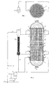
- FIG.1 shows a heat exchanger vessel 1 which has a tubular mid section 2 and dome-shaped top and bottom sections 3 and 4, known as headers, which are separated from each other by disc-shaped partitioning walls 5 and 6.
- the tubular mid section 2 comprises a bundle of heat exchanger tubes 7 which extend through openings 8 in the disc-shaped partitioning walls 5 and 6 such that the interior of the heat exchanger tubes 7 is connected in fluid communication for the first fluid with the interior of the dome-shaped top and bottom sections 3 and 4.
- An inlet 9 for a first fluid which may be a high pressure and high temperature natural gas or other low or high pressure fluid, is arranged at the top of the dome-shaped top section 3.
- An outlet 10 for the first fluid is arranged at the bottom of the dome-shaped bottom section 4 of the vessel 1.
- the first fluid flows via the inlet 9 into the interior of the top section 3 of the vessel 1 and flows via the interior of the bundle of heat exchanger tubes 7 into the interior of the bottom section 4 of the vessel 1 and is then discharged via the outlet 10.
- a second fluid which is in the example shown water, is pumped from a body of water 11, such as a river, lake, sea, ocean or an underground aquifer, and used as a coolant for cooling the first fluid.
- the cooling water is pumped by a pump 12, possibly pre-treated using filters 21 and/or chemical injection, via a pair of lower inlets 13 into the interior of the tubular mid section 2 which surrounds the heat exchanger pipes 7.
- a mixture of water and cleaning particles is injected into the interior of the tubular mid section 2 via a pair of intermediate inlets 14. This mixture is mixed up with the water injected via the lower inlets 13 and induced to flow up through the interior of the tubular mid section 2, such that the cleaning particles flow along the heat exchanger tubes 7 and thereby continuously remove any offset of scaling and/or other fouling from the outer surfaces of the tubes 7 as well as from the inner surface of the tubular wall of the tubular mid section 2.
- a series of flow and particle distribution plates 22 is arranged at different levels in the interior, including one between inlet of the second fluid 13 and the intermediate inlets 14 of the tubular mid section 2 to create an equally distributed flow of the cooling water and fluidized bed of cleaning particles throughout the height of the tubular mid section 2.
- the distribution plates also providing firmness to the vessel 1 and the tubes 7, could be perforated plates or include caps, nozzles or devices to preventing backflow of the particles. Since the abrasive particles in combination with the distribution plates continuously remove the film-layer and mix the fluid flow, no baffles are required, minimizing the overall pressure drop and pumping duty.
- the mixture of water and cleaning particles is discharged from the interior of the tubular mid section 2 via a pair of upper outlets 16 and directed into a water/cleaning particle separator 17 in which a stream of hot water 18 is separated from a cleaning particles stream 19.
- the hot water stream 18 is discharged into the body of water 11 and the cleaning particles stream 19 is mixed with a cold water stream 20 and pumped back into the interior of the tubular mid section 2 of the heat exchanger vessel 1 via the intermediate inlets 14.
- the hot water stream 18 is commingled with a fraction of the cold water flow before being discharged into the body of water 11. Turndown is managed by either reducing the second fluid flow and/or by commingling the cold second fluid flow with a fraction of the hot fluid flow 18.
- the cleaning action of the cleaning particles permits heating up of the water in the tubular mid section 2 of the vessel 1 to a much higher temperature than in conventional heat exchanger vessels.
- conventional heat exchanger vessels known as direct and indirect seawater HEX assemblies, which are generally used in ships, power plants and offshore platforms
- the skin temperature of the cooling water at the wall of the heat exchanger tubes should remain lower than about 50-55 degrees Celsius to avoid scaling and other fouling of the heat exchanger tubes and the inner wall of the vessel.
- the skin temperature of the water flowing along the outer surfaces of the heat exchanger tubes 7 may well exceed 80 degrees Celsius, because any scale precipitation will be abraded away by the cleaning particles.
- the increase of the permitted water temperature leads to a significant reduction of the size of the tubular mid section 2, of the corresponding length and weight of the heat exchanger tubes 7, of the flux and velocity of the cooling water and of the required power of the water circulation pump 12.
- the inhibition of offset of fouling significantly reduces the maintenance required and increases the availability of the plant.
- High pressure gas only flows into the dome-shaped upper and lower parts 3 and 4 of the vessel 1 and into the interior of the heat exchanger tubes 7. Therefore only the heat exchanger tubes 7 and the dome-shaped upper and lower parts 3 and 4 of the heat exchanger vessel 1 need to have a high wall thickness and to be made of high strength steel, titanium or other alloys.
- the tubular mid section 2 of the heat exchanger is filled with low pressure water and can have a relatively low wall thickness.
- the use of a heat exchanger vessel 1 with a smaller tubular mid section 2 than conventional heat exchanger vessels and the use of a tubular mid section 2 with a relatively low wall thickness creates a heat exchanger vessel 1 which is significantly smaller and lighter than conventional heat exchanger vessels.
- heat exchanger vessel may have the first fluid flow from the bottom to the top, co-current with the second fluid.
- heat exchanger vessel according to the invention may have a square shape, as also known in aircooler banks, instead of a round shape and that the top and bottom sections 3 and 4 may be box-shaped instead of dome-shaped as shown in the drawings.
- the heat exchanger vessel according to the invention may comprise a bellow 23 to inhibit e.g. thermal expansion and/or compression stresses, if that turns out to be required for mechanical reason.
- the invention may have the injection of the cleaning particles in the second fluid upstream the heat exchanger vessel, near the intake of the second fluid from the second fluid supply body 11.
- the amount of water inlets and outlets 13, 14, 16 may be increased to further equalize the upward water flux and the fluidized bed of cleaning particles in the interior of the vessel 2.
Landscapes
- Engineering & Computer Science (AREA)
- Mechanical Engineering (AREA)
- General Engineering & Computer Science (AREA)
- Chemical & Material Sciences (AREA)
- Combustion & Propulsion (AREA)
- Physics & Mathematics (AREA)
- Thermal Sciences (AREA)
- Heat-Exchange Devices With Radiators And Conduit Assemblies (AREA)
- Cleaning In General (AREA)
Claims (9)
- Ein Wärmetauschergefäß (1), umfassend einen Außenmantel (2), in welchem ein Bündel von Wärmetauscherrohren (7) angeordnet ist, welches Bündel von Wärmetauscherrohren (7) an einen Einlass (9) und einen Auslass (10) für ein erstes Fluid angeschlossen ist, und der Außenmantel (2) wenigstens einen Einlass (13, 14) und wenigstens einen Auslass (16) für ein zweites Fluid umfasst, wobei wenigstens ein Einlass (14) für das zweite Fluid mit Mitteln zur Zuführung von Teilchen zum Zuführen von Reinigungsteilchen (19) in den Raum zwischen den äußeren Oberflächen der Wärmetauscherrohre (7) und der inneren Oberfläche des Wärmetauschergefäßes (2) ausgestattet ist, und der Auslass (16) für das zweite Fluid Mittel (17) zum Entfernen von Teilchen (19) aus dem zweiten Fluid und zum erneuten Zuführen von Teilchen (19) zu wenigstens einem Einlass des zweiten Fluids (14) umfasst, wobei
die Wärmetauscherrohre (7) in einem im Wesentlichen röhrenförmigen Mittelbereich (2) des Gefäßes angeordnet sind, und sich im Wesentlichen parallel zueinander zwischen einem Paar von perforierten Trennwänden (5, 6) erstrecken, welche in der Nähe der Enden des röhrenförmigen Mittelbereichs (2) angeordnet sind, und der Einlass (13, 14) für das zweite Fluid an einer Stelle in der Nähe einer Trennwand (6) in das Innere des röhrenförmigen Mittelbereichs (2) mündet, und der Auslass (16) für das zweite Fluid, an einer Stelle in der Nähe der anderen Trennwand (5), in das Innere des röhrenförmigen Mittelbereichs mündet;
dadurch gekennzeichnet, dass wenigstens ein Verteilerboden (22) in dem Raum zwischen den äußeren Oberflächen der Wärmetauscherrohre (7) und der inneren Oberfläche des röhrenförmigen Mittelbereichs (2) des Wärmetauschergefäßes angeordnet ist, um einen gleichmäßigen Fluss des Kühlwassers und des fluidisierten Bettes an Reinigungsteilchen in der ganzen Höhe des röhrenförmigen Mittelbereichs (2) zu erzeugen. - Wärmetauschergefäß nach Anspruch 1, wobei das zweite Fluid Wasser ist und die Reinigungsteilchen Körnchen, Glas, Metall, Fasern, Kunststoff und/oder geschnittenen Draht umfassen; und ein Separator (17) zum Abtrennen der Reinigungsteilchen aus dem Wasser in der Nähe des Auslasses (16) für das zweite Fluid angeordnet ist, welcher Separator (17) an eine Reinigungsteilchen-Umlaufleitung angeschlossen ist, welche an wenigstens einen Fluideinlass (14) für das zweite Fluid angeschlossen ist, und durch welche in Verwendung befindliche Reinigungsteilchen (19) aus wenigstens einem Fluidauslass (16) zu wenigstens einem Fluideinlass (14) für das zweite Fluid erneut zugeführt werden.
- Wärmetauschergefäß nach Anspruch 2, wobei wenigstens ein Einlass (13) für das zweite Fluid mit Mitteln zum Pumpen von Wasser (11) aus einem Wasserkörper in den Außenmantel (2) des Wärmetauschergefäßes (1) ausgestattet ist, und wobei wenigstens ein Auslass (16) für das zweite Fluid mit Mitteln (18) zum Abfließen von Wasser in diesen Wasserkörper (11) ausgestattet ist.
- Wärmetauscher nach Anspruch 3, wobei der Außenmantel (2) eine Vielzahl an Wassereinlässen (13, 14) umfasst, und wenigstens einer (13) dieser Einlässe an eine Pumpe (12) angeschlossen ist, über welche Wasser aus diesem Wasserkörper (11) in den Raum zwischen den Außenwänden der Wärmetauscherrohre (7) gepumpt wird, und wenigstens ein anderer dieser Einlässe (14) an die Reinigungsteilchen-Umlaufleitung angeschlossen ist.
- Wärmetauscher nach einem der vorstehenden Ansprüche, wobei sich die Mittel zur Zuführung der Reinigungsteilchen (19) in dem zweiten Fluid, stromaufwärts des Wärmetauschergefäßes (1), in der Nähe des Einlaufs (20) des zweiten Fluids befinden.
- Wärmetauscher nach Anspruch 1, wobei der Verteilerboden eine perforierte Platte ist und/oder Aufsätze, Düsen oder Vorrichtungen zum Verhindern des Rückflusses der Teilchen umfasst.
- Wärmetauscher nach Anspruch 1, wobei der Wärmetauscher (1) derart konfiguriert ist, dass die Scheuermittelteilchen in Kombination mit dem Verteilerboden oder den Verteilerböden (22) die statische Fluidfilmschicht, welche die äußeren Oberflächen der Wärmetauscherrohre (7) umgibt, kontinuierlich entfernen, und den Fluss des zweiten Fluids im röhrenförmigen Mittelbereich (2) des Gefäßes mischen, und dadurch den Wärmeaustausch zwischen dem ersten und dem zweiten Fluid verbessern.
- Wärmetauscher nach einem der vorstehenden Ansprüche, wobei der Wärmeaustauscher (1) unterseeisch angeordnet ist.
- Verfahren zum erneuten Zurückführen von Reinigungsteilchen in ein Wärmetauschergefäß (1) nach Anspruch 1, umfassend einen Außenmantel, in welchem ein Bündel von Wärmetauscherrohren (7) angeordnet ist, welches Bündel von Wärmetauscherrohren (7) an einen Einlass (9) und einen Auslass (10) für ein erstes Fluid angeschlossen ist, und der Außenmantel wenigstens einen Einlass (13, 14) und wenigstens einen Auslass (16) für ein zweites Fluid umfasst, wobei ein Gemisch aus dem zweiten Fluid und Reinigungsteilchen über wenigstens einen Einlass (14) für das zweite Fluid in den Raum zwischen den äußeren Oberflächen der Wärmetauscherrohre (7) und der inneren Oberfläche des Wärmetauschergefäßes (2) zugeführt wird, und jeder Auslass (16) für das zweite Fluid Mittel zum Entfernen von Teilchen aus dem zweiten Fluid und zum erneuten Zuführen von Teilchen zu wenigstens einem Einlass (14) des zweiten Fluids umfasst; wobei
die Wärmetauscherrohre (7) in einem im Wesentlichen röhrenförmigen Mittelbereich (2) des Gefäßes (1) angeordnet sind, und sich im Wesentlichen parallel zueinander zwischen einem Paar perforierter kreisförmiger Trennwände (5, 6) erstrecken, welche in der Nähe der Enden dieses röhrenförmigen Mittelbereichs (2) angeordnet sind, und das Gemisch des zweiten Fluids und der Reinigungsteilchen (19) über einen Einlass (14), welcher in der Nähe einer Trennwand (6) in das Innere des röhrenförmigen Mittelbereichs (2) mündet, in diesen Raum zugeführt wird, und über einen Auslass (16), welcher in der Nähe der anderen perforierten Trennwand (5) in das Innere des röhrenförmigen Mittelbereichs mündet, aus diesem Raum entfernt wird; und das erste Fluid, das durch das Innere der Wärmetauscherrohre (7) fließt, ein Strom von Erdgas ist, und das zweite Fluid, das durch den Raum zwischen den äußeren Oberflächen der Wärmetauscherrohre (7) und der inneren Oberfläche des röhrenförmigen Mittelbereichs (2) des Wärmetauschergefäßes (1) fließt, Wasser ist; und der statische Druck des Stroms aus Erdgas, welcher durch das Innere der Wärmetauscherrohre (7) fließt, höher als der statische Druck des Stroms aus Wasser und Reinigungsteilchen (19) ist, der durch den Raum zwischen den äußeren Oberflächen der Wärmetauscherrohre (7) und der inneren Oberfläche des röhrenförmigen Mittelbereichs (2) des Wärmetauschergefäßes (11) fließt.
Priority Applications (1)
| Application Number | Priority Date | Filing Date | Title |
|---|---|---|---|
| EP05776135A EP1782014B1 (de) | 2004-07-29 | 2005-07-28 | Wärmetauscherbehälter mit mitteln zur rückführung von reinigungspartikeln |
Applications Claiming Priority (3)
| Application Number | Priority Date | Filing Date | Title |
|---|---|---|---|
| EP04103652 | 2004-07-29 | ||
| EP05776135A EP1782014B1 (de) | 2004-07-29 | 2005-07-28 | Wärmetauscherbehälter mit mitteln zur rückführung von reinigungspartikeln |
| PCT/EP2005/053695 WO2006010771A1 (en) | 2004-07-29 | 2005-07-28 | Heat exchanger vessel with means for recirculating cleaning particles |
Publications (2)
| Publication Number | Publication Date |
|---|---|
| EP1782014A1 EP1782014A1 (de) | 2007-05-09 |
| EP1782014B1 true EP1782014B1 (de) | 2008-05-07 |
Family
ID=34929392
Family Applications (1)
| Application Number | Title | Priority Date | Filing Date |
|---|---|---|---|
| EP05776135A Expired - Lifetime EP1782014B1 (de) | 2004-07-29 | 2005-07-28 | Wärmetauscherbehälter mit mitteln zur rückführung von reinigungspartikeln |
Country Status (12)
| Country | Link |
|---|---|
| US (1) | US7900691B2 (de) |
| EP (1) | EP1782014B1 (de) |
| CN (1) | CN101010557B (de) |
| AT (1) | ATE394643T1 (de) |
| AU (1) | AU2005266333B2 (de) |
| BR (1) | BRPI0513861A (de) |
| CA (1) | CA2575208A1 (de) |
| DE (1) | DE602005006581D1 (de) |
| EA (1) | EA009751B1 (de) |
| NO (1) | NO20071114L (de) |
| UA (1) | UA89198C2 (de) |
| WO (1) | WO2006010771A1 (de) |
Families Citing this family (10)
| Publication number | Priority date | Publication date | Assignee | Title |
|---|---|---|---|---|
| US8968431B2 (en) * | 2008-06-05 | 2015-03-03 | Synthesis Energy Systems, Inc. | Method and apparatus for cooling solid particles under high temperature and pressure |
| GB2468920A (en) * | 2009-03-27 | 2010-09-29 | Framo Eng As | Subsea cooler for cooling a fluid flowing in a subsea flow line |
| US9303491B2 (en) | 2009-03-27 | 2016-04-05 | Framo Engineering As | Subsea cooler and method for cleaning the subsea cooler |
| NO333597B1 (no) * | 2009-07-15 | 2013-07-15 | Fmc Kongsberg Subsea As | Undervannskjoler |
| NO334268B1 (no) * | 2011-04-15 | 2014-01-27 | Apply Nemo As | En undersjøisk kjøleanordning |
| BR112013032865B1 (pt) * | 2011-07-01 | 2020-12-01 | Equinor Energy As | trocador de calor submarino e método para o controle de temperatura |
| CN105229770B (zh) | 2013-05-03 | 2017-05-10 | 项晓东 | 用于利用相变热交换的高亮度x射线管的冷却装置 |
| US20160341499A1 (en) * | 2015-05-19 | 2016-11-24 | Uop Llc | Process for online cleaning of mto reactor effluent cooler |
| CN106288934B (zh) * | 2015-06-01 | 2018-12-25 | 中国石油天然气集团公司 | 换热器在线除垢方法及装置 |
| KR102533335B1 (ko) * | 2016-11-28 | 2023-05-17 | 캔두 에너지 인코포레이티드 | 열 교환기를 세정하는 시스템 및 방법 |
Family Cites Families (25)
| Publication number | Priority date | Publication date | Assignee | Title |
|---|---|---|---|---|
| US1795348A (en) * | 1927-03-30 | 1931-03-10 | Westinghouse Electric & Mfg Co | Condenser-cleaning system |
| DE1083058B (de) * | 1959-07-10 | 1960-06-09 | Schmidt Sche Heissdampf | Verfahren zum Reinhalten der Heizflaechen von Abhitzekesseln und Einrichtung zur Durchfuehrung des Verfahrens |
| JPS5111253B2 (de) * | 1972-03-24 | 1976-04-09 | ||
| US4300625A (en) * | 1975-01-21 | 1981-11-17 | Mikhailov Gerold M | Preventing deposition on the inner surfaces of heat exchange apparatus |
| US4208220A (en) * | 1978-05-15 | 1980-06-17 | The Research Corporation Of The University Of Hawaii | Method and apparatus for cleaning heat exchanger tubes mounted transversely to vertical flow of seawater |
| US4237962A (en) * | 1978-08-11 | 1980-12-09 | Vandenhoeck J Paul | Self-cleaning heat exchanger |
| KR860000855B1 (ko) * | 1980-06-30 | 1986-07-09 | 가부시기가이샤 히다찌 세이사꾸쇼 | 열교환기 열전도 도관의 세정장치 |
| FR2496861A1 (fr) * | 1980-12-23 | 1982-06-25 | Creusot Loire | Echangeur de chaleur a plaques |
| US4509589A (en) * | 1982-08-05 | 1985-04-09 | Tosco Corporation | Circulating bed heat exchanger for cooling shale ash |
| CA1216572A (en) * | 1982-11-26 | 1987-01-13 | Hubertus W.A.A. Dries | Method and apparatus for continuously cleaning a heat exchanger during operation |
| JPS6199100A (ja) * | 1984-10-19 | 1986-05-17 | Fuji Heavy Ind Ltd | 排気ガス熱交換器 |
| FR2639851B1 (fr) * | 1988-12-01 | 1991-10-18 | Atochem | Procede de nettoyage de tubes en fonctionnement a l'aide de particules |
| CA2030790C (fr) * | 1989-04-14 | 2001-02-13 | Eric Lenglet | Procede et appareillage pour le decokage d'une installation de vapocraquage |
| NL9000919A (nl) * | 1990-04-18 | 1991-11-18 | Eskla Bv | Werkwijze voor het reinigen van de wanden van warmtewisselaars en warmtewisselaar met middelen voor deze reiniging. |
| US5336331A (en) * | 1992-01-22 | 1994-08-09 | Jenkins Jerry Y | Continuous condenser backflush and cleaning systems and methods for use thereof |
| NL9300666A (nl) | 1993-04-20 | 1994-11-16 | Bronswerk Heat Transfer Bv | Inrichting voor het uitvoeren van een fysisch en/of chemisch proces, zoals een warmtewisselaar. |
| IL111666A (en) * | 1993-11-18 | 1996-10-31 | Cqm Ltd | Cleaning system for cleaning the face of liquid conductor pipes and an ancillary device |
| DE29610900U1 (de) | 1996-06-21 | 1997-10-16 | Taprogge GmbH, 58300 Wetter | Kugelschleuse für eine Einrichtung zum Rückführen von Kugeln zum Reinigen der Rohre von Kühlsystemen |
| DE29610898U1 (de) | 1996-06-21 | 1997-10-23 | Taprogge GmbH, 58300 Wetter | Siebeinrichtung zum Ausscheiden von Kugeln zum Reinigen der Rohre eines Wärmetauschers, Kondensators oder ähnlichem aus einer Kühlmittelleitung |
| CN1098736C (zh) * | 1996-06-25 | 2003-01-15 | 球技术能源有限公司 | 清洗流体输送管道的清洗系统 |
| NL1005514C2 (nl) | 1997-03-12 | 1998-09-15 | Bronswerk Heat Transfer Bv | Inrichting voor het uitvoeren van een fysisch en/of chemisch proces, zoals een warmtewisselaar. |
| NL1005517C2 (nl) | 1997-03-12 | 1998-09-15 | Bronswerk Heat Transfer Bv | Inrichting voor het uitvoeren van een fysisch en/of chemisch proces, zoals een warmtewisselaar. |
| CN2302495Y (zh) * | 1997-06-16 | 1998-12-30 | 大连华峰发展公司 | 一种热交换器自动清洗设备 |
| US6703534B2 (en) * | 1999-12-30 | 2004-03-09 | Marathon Oil Company | Transport of a wet gas through a subsea pipeline |
| CN2580386Y (zh) * | 2002-09-28 | 2003-10-15 | 倪永刚 | 冷凝器热交换管内壁在线自动清洗装置 |
-
2005
- 2005-07-28 EP EP05776135A patent/EP1782014B1/de not_active Expired - Lifetime
- 2005-07-28 UA UAA200702170A patent/UA89198C2/ru unknown
- 2005-07-28 AU AU2005266333A patent/AU2005266333B2/en not_active Ceased
- 2005-07-28 CA CA002575208A patent/CA2575208A1/en not_active Abandoned
- 2005-07-28 EA EA200700361A patent/EA009751B1/ru not_active IP Right Cessation
- 2005-07-28 AT AT05776135T patent/ATE394643T1/de not_active IP Right Cessation
- 2005-07-28 US US11/658,523 patent/US7900691B2/en not_active Expired - Fee Related
- 2005-07-28 DE DE602005006581T patent/DE602005006581D1/de not_active Expired - Lifetime
- 2005-07-28 WO PCT/EP2005/053695 patent/WO2006010771A1/en not_active Ceased
- 2005-07-28 BR BRPI0513861-2A patent/BRPI0513861A/pt not_active Application Discontinuation
- 2005-07-28 CN CN2005800255230A patent/CN101010557B/zh not_active Expired - Fee Related
-
2007
- 2007-02-27 NO NO20071114A patent/NO20071114L/no not_active Application Discontinuation
Also Published As
| Publication number | Publication date |
|---|---|
| WO2006010771A1 (en) | 2006-02-02 |
| BRPI0513861A (pt) | 2008-05-20 |
| EP1782014A1 (de) | 2007-05-09 |
| CA2575208A1 (en) | 2006-02-02 |
| US7900691B2 (en) | 2011-03-08 |
| AU2005266333B2 (en) | 2008-10-23 |
| CN101010557A (zh) | 2007-08-01 |
| UA89198C2 (ru) | 2010-01-11 |
| CN101010557B (zh) | 2011-06-08 |
| EA009751B1 (ru) | 2008-04-28 |
| AU2005266333A1 (en) | 2006-02-02 |
| DE602005006581D1 (de) | 2008-06-19 |
| EA200700361A1 (ru) | 2007-08-31 |
| US20080302511A1 (en) | 2008-12-11 |
| NO20071114L (no) | 2007-04-27 |
| ATE394643T1 (de) | 2008-05-15 |
Similar Documents
| Publication | Publication Date | Title |
|---|---|---|
| RU2455399C2 (ru) | Система охлаждения и очистки дымового газа | |
| AU2005266333B2 (en) | Heat exchanger vessel with means for recirculating cleaning particles | |
| JP5903272B2 (ja) | 廃熱を使用する小型廃水濃縮装置 | |
| FI113463B (fi) | Vesialuksen yhdistetty poistokaasun ja painolastiveden käsittelyjärjestely ja menetelmä vesialuksen painolastiveden käsittelemiseksi | |
| US20150135710A1 (en) | Industrial Ocean Thermal Energy Conversion Processes | |
| US20140150994A1 (en) | Air-cooled heat exchanger and system and method of using the same to remove waste thermal energy from radioactive materials | |
| WO2009146504A1 (en) | Heat treatment and disinfection system for fluids | |
| JP6618818B2 (ja) | 多管式熱交換器、その伝熱管洗浄方法 | |
| CN110562412A (zh) | 一种船用舷外冷却器清洗系统 | |
| KR100743909B1 (ko) | 선박의 발라스트 수 침전물 처리기능을 갖는 다목적해수교환장치 | |
| CN112466485A (zh) | 一种非能动余热排出系统缓冲水箱 | |
| US5257296A (en) | Steam generator chemical solvent mixing system and method | |
| KR20170098301A (ko) | 개선된 무폐수 해수 담수화를 위한 방법 및 장치 | |
| CN1039574C (zh) | 多单元加热系统 | |
| CN108877966A (zh) | 一种用于浮动式核电站的闭式非能动安全壳冷却系统 | |
| EP3092379B1 (de) | Abgas scrubber und schiff | |
| CN109384272B (zh) | 造水装置 | |
| RU2729566C1 (ru) | Устройство для подводного охлаждения потока углеводородной смеси и способ подводного охлаждения потока углеводородной смеси | |
| Ezgi et al. | Optimization of heat exchanger cleaning cycle on a ship | |
| CN210503144U (zh) | 一种船舶轮机结构散热装置 | |
| RU2371228C2 (ru) | Способ подогрева накипеобразующих растворов при выпаривании и теплообменник для его осуществления | |
| Bom | Selection of alloys for multi-stage flash distillation plant | |
| HK40079323A (en) | Fresh water generation device | |
| RU2277671C2 (ru) | Компрессорная станция газопровода | |
| KR900006808B1 (ko) | 선박의 냉각장치 |
Legal Events
| Date | Code | Title | Description |
|---|---|---|---|
| PUAI | Public reference made under article 153(3) epc to a published international application that has entered the european phase |
Free format text: ORIGINAL CODE: 0009012 |
|
| 17P | Request for examination filed |
Effective date: 20070124 |
|
| AK | Designated contracting states |
Kind code of ref document: A1 Designated state(s): AT BE BG CH CY CZ DE DK EE ES FI FR GB GR HU IE IS IT LI LT LU LV MC NL PL PT RO SE SI SK TR |
|
| 17Q | First examination report despatched |
Effective date: 20070601 |
|
| DAX | Request for extension of the european patent (deleted) | ||
| GRAP | Despatch of communication of intention to grant a patent |
Free format text: ORIGINAL CODE: EPIDOSNIGR1 |
|
| GRAS | Grant fee paid |
Free format text: ORIGINAL CODE: EPIDOSNIGR3 |
|
| GRAA | (expected) grant |
Free format text: ORIGINAL CODE: 0009210 |
|
| AK | Designated contracting states |
Kind code of ref document: B1 Designated state(s): AT BE BG CH CY CZ DE DK EE ES FI FR GB GR HU IE IS IT LI LT LU LV MC NL PL PT RO SE SI SK TR |
|
| REG | Reference to a national code |
Ref country code: GB Ref legal event code: FG4D |
|
| REG | Reference to a national code |
Ref country code: CH Ref legal event code: EP |
|
| REG | Reference to a national code |
Ref country code: IE Ref legal event code: FG4D Free format text: LANGUAGE OF EP DOCUMENT: FRENCH |
|
| REF | Corresponds to: |
Ref document number: 602005006581 Country of ref document: DE Date of ref document: 20080619 Kind code of ref document: P |
|
| PG25 | Lapsed in a contracting state [announced via postgrant information from national office to epo] |
Ref country code: SI Free format text: LAPSE BECAUSE OF FAILURE TO SUBMIT A TRANSLATION OF THE DESCRIPTION OR TO PAY THE FEE WITHIN THE PRESCRIBED TIME-LIMIT Effective date: 20080507 |
|
| PG25 | Lapsed in a contracting state [announced via postgrant information from national office to epo] |
Ref country code: FI Free format text: LAPSE BECAUSE OF FAILURE TO SUBMIT A TRANSLATION OF THE DESCRIPTION OR TO PAY THE FEE WITHIN THE PRESCRIBED TIME-LIMIT Effective date: 20080507 Ref country code: ES Free format text: LAPSE BECAUSE OF FAILURE TO SUBMIT A TRANSLATION OF THE DESCRIPTION OR TO PAY THE FEE WITHIN THE PRESCRIBED TIME-LIMIT Effective date: 20080818 |
|
| PG25 | Lapsed in a contracting state [announced via postgrant information from national office to epo] |
Ref country code: LV Free format text: LAPSE BECAUSE OF FAILURE TO SUBMIT A TRANSLATION OF THE DESCRIPTION OR TO PAY THE FEE WITHIN THE PRESCRIBED TIME-LIMIT Effective date: 20080507 Ref country code: AT Free format text: LAPSE BECAUSE OF FAILURE TO SUBMIT A TRANSLATION OF THE DESCRIPTION OR TO PAY THE FEE WITHIN THE PRESCRIBED TIME-LIMIT Effective date: 20080507 Ref country code: PL Free format text: LAPSE BECAUSE OF FAILURE TO SUBMIT A TRANSLATION OF THE DESCRIPTION OR TO PAY THE FEE WITHIN THE PRESCRIBED TIME-LIMIT Effective date: 20080507 |
|
| PG25 | Lapsed in a contracting state [announced via postgrant information from national office to epo] |
Ref country code: IS Free format text: LAPSE BECAUSE OF FAILURE TO SUBMIT A TRANSLATION OF THE DESCRIPTION OR TO PAY THE FEE WITHIN THE PRESCRIBED TIME-LIMIT Effective date: 20080907 |
|
| PG25 | Lapsed in a contracting state [announced via postgrant information from national office to epo] |
Ref country code: SE Free format text: LAPSE BECAUSE OF FAILURE TO SUBMIT A TRANSLATION OF THE DESCRIPTION OR TO PAY THE FEE WITHIN THE PRESCRIBED TIME-LIMIT Effective date: 20080807 Ref country code: LT Free format text: LAPSE BECAUSE OF FAILURE TO SUBMIT A TRANSLATION OF THE DESCRIPTION OR TO PAY THE FEE WITHIN THE PRESCRIBED TIME-LIMIT Effective date: 20080507 Ref country code: DK Free format text: LAPSE BECAUSE OF FAILURE TO SUBMIT A TRANSLATION OF THE DESCRIPTION OR TO PAY THE FEE WITHIN THE PRESCRIBED TIME-LIMIT Effective date: 20080507 Ref country code: CZ Free format text: LAPSE BECAUSE OF FAILURE TO SUBMIT A TRANSLATION OF THE DESCRIPTION OR TO PAY THE FEE WITHIN THE PRESCRIBED TIME-LIMIT Effective date: 20080507 |
|
| PG25 | Lapsed in a contracting state [announced via postgrant information from national office to epo] |
Ref country code: PT Free format text: LAPSE BECAUSE OF FAILURE TO SUBMIT A TRANSLATION OF THE DESCRIPTION OR TO PAY THE FEE WITHIN THE PRESCRIBED TIME-LIMIT Effective date: 20081007 Ref country code: RO Free format text: LAPSE BECAUSE OF FAILURE TO SUBMIT A TRANSLATION OF THE DESCRIPTION OR TO PAY THE FEE WITHIN THE PRESCRIBED TIME-LIMIT Effective date: 20080507 Ref country code: SK Free format text: LAPSE BECAUSE OF FAILURE TO SUBMIT A TRANSLATION OF THE DESCRIPTION OR TO PAY THE FEE WITHIN THE PRESCRIBED TIME-LIMIT Effective date: 20080507 Ref country code: BE Free format text: LAPSE BECAUSE OF FAILURE TO SUBMIT A TRANSLATION OF THE DESCRIPTION OR TO PAY THE FEE WITHIN THE PRESCRIBED TIME-LIMIT Effective date: 20080507 |
|
| PLBE | No opposition filed within time limit |
Free format text: ORIGINAL CODE: 0009261 |
|
| STAA | Information on the status of an ep patent application or granted ep patent |
Free format text: STATUS: NO OPPOSITION FILED WITHIN TIME LIMIT |
|
| PG25 | Lapsed in a contracting state [announced via postgrant information from national office to epo] |
Ref country code: MC Free format text: LAPSE BECAUSE OF NON-PAYMENT OF DUE FEES Effective date: 20080731 |
|
| 26N | No opposition filed |
Effective date: 20090210 |
|
| REG | Reference to a national code |
Ref country code: IE Ref legal event code: MM4A |
|
| PG25 | Lapsed in a contracting state [announced via postgrant information from national office to epo] |
Ref country code: BG Free format text: LAPSE BECAUSE OF FAILURE TO SUBMIT A TRANSLATION OF THE DESCRIPTION OR TO PAY THE FEE WITHIN THE PRESCRIBED TIME-LIMIT Effective date: 20080807 Ref country code: EE Free format text: LAPSE BECAUSE OF FAILURE TO SUBMIT A TRANSLATION OF THE DESCRIPTION OR TO PAY THE FEE WITHIN THE PRESCRIBED TIME-LIMIT Effective date: 20080507 |
|
| REG | Reference to a national code |
Ref country code: FR Ref legal event code: ST Effective date: 20090331 |
|
| PG25 | Lapsed in a contracting state [announced via postgrant information from national office to epo] |
Ref country code: IE Free format text: LAPSE BECAUSE OF NON-PAYMENT OF DUE FEES Effective date: 20080728 |
|
| PG25 | Lapsed in a contracting state [announced via postgrant information from national office to epo] |
Ref country code: FR Free format text: LAPSE BECAUSE OF NON-PAYMENT OF DUE FEES Effective date: 20080731 |
|
| REG | Reference to a national code |
Ref country code: CH Ref legal event code: PL |
|
| PG25 | Lapsed in a contracting state [announced via postgrant information from national office to epo] |
Ref country code: LI Free format text: LAPSE BECAUSE OF NON-PAYMENT OF DUE FEES Effective date: 20090731 Ref country code: CH Free format text: LAPSE BECAUSE OF NON-PAYMENT OF DUE FEES Effective date: 20090731 |
|
| PG25 | Lapsed in a contracting state [announced via postgrant information from national office to epo] |
Ref country code: HU Free format text: LAPSE BECAUSE OF FAILURE TO SUBMIT A TRANSLATION OF THE DESCRIPTION OR TO PAY THE FEE WITHIN THE PRESCRIBED TIME-LIMIT Effective date: 20081108 Ref country code: LU Free format text: LAPSE BECAUSE OF NON-PAYMENT OF DUE FEES Effective date: 20080728 Ref country code: CY Free format text: LAPSE BECAUSE OF FAILURE TO SUBMIT A TRANSLATION OF THE DESCRIPTION OR TO PAY THE FEE WITHIN THE PRESCRIBED TIME-LIMIT Effective date: 20080507 |
|
| PG25 | Lapsed in a contracting state [announced via postgrant information from national office to epo] |
Ref country code: TR Free format text: LAPSE BECAUSE OF FAILURE TO SUBMIT A TRANSLATION OF THE DESCRIPTION OR TO PAY THE FEE WITHIN THE PRESCRIBED TIME-LIMIT Effective date: 20080507 |
|
| PG25 | Lapsed in a contracting state [announced via postgrant information from national office to epo] |
Ref country code: GR Free format text: LAPSE BECAUSE OF FAILURE TO SUBMIT A TRANSLATION OF THE DESCRIPTION OR TO PAY THE FEE WITHIN THE PRESCRIBED TIME-LIMIT Effective date: 20080808 |
|
| PGFP | Annual fee paid to national office [announced via postgrant information from national office to epo] |
Ref country code: NL Payment date: 20130710 Year of fee payment: 9 |
|
| PGFP | Annual fee paid to national office [announced via postgrant information from national office to epo] |
Ref country code: GB Payment date: 20130731 Year of fee payment: 9 |
|
| PGFP | Annual fee paid to national office [announced via postgrant information from national office to epo] |
Ref country code: IT Payment date: 20130727 Year of fee payment: 9 |
|
| PGFP | Annual fee paid to national office [announced via postgrant information from national office to epo] |
Ref country code: DE Payment date: 20130930 Year of fee payment: 9 |
|
| REG | Reference to a national code |
Ref country code: DE Ref legal event code: R119 Ref document number: 602005006581 Country of ref document: DE |
|
| REG | Reference to a national code |
Ref country code: NL Ref legal event code: V1 Effective date: 20150201 |
|
| GBPC | Gb: european patent ceased through non-payment of renewal fee |
Effective date: 20140728 |
|
| PG25 | Lapsed in a contracting state [announced via postgrant information from national office to epo] |
Ref country code: NL Free format text: LAPSE BECAUSE OF NON-PAYMENT OF DUE FEES Effective date: 20150201 |
|
| PG25 | Lapsed in a contracting state [announced via postgrant information from national office to epo] |
Ref country code: DE Free format text: LAPSE BECAUSE OF NON-PAYMENT OF DUE FEES Effective date: 20150203 Ref country code: IT Free format text: LAPSE BECAUSE OF NON-PAYMENT OF DUE FEES Effective date: 20140728 |
|
| REG | Reference to a national code |
Ref country code: DE Ref legal event code: R119 Ref document number: 602005006581 Country of ref document: DE Effective date: 20150203 |
|
| PG25 | Lapsed in a contracting state [announced via postgrant information from national office to epo] |
Ref country code: GB Free format text: LAPSE BECAUSE OF NON-PAYMENT OF DUE FEES Effective date: 20140728 |