EP1781913B1 - Logement a point d'appui d'un organe - Google Patents
Logement a point d'appui d'un organe Download PDFInfo
- Publication number
- EP1781913B1 EP1781913B1 EP05782545A EP05782545A EP1781913B1 EP 1781913 B1 EP1781913 B1 EP 1781913B1 EP 05782545 A EP05782545 A EP 05782545A EP 05782545 A EP05782545 A EP 05782545A EP 1781913 B1 EP1781913 B1 EP 1781913B1
- Authority
- EP
- European Patent Office
- Prior art keywords
- holder
- housing
- pivot bearing
- unit
- traction
- Prior art date
- Legal status (The legal status is an assumption and is not a legal conclusion. Google has not performed a legal analysis and makes no representation as to the accuracy of the status listed.)
- Expired - Fee Related
Links
- 238000002485 combustion reaction Methods 0.000 claims description 19
- 239000007858 starting material Substances 0.000 claims description 7
- 238000009434 installation Methods 0.000 claims description 4
- 238000003754 machining Methods 0.000 claims description 2
- 238000007667 floating Methods 0.000 description 4
- 238000010079 rubber tapping Methods 0.000 description 4
- 238000013016 damping Methods 0.000 description 2
- 238000007789 sealing Methods 0.000 description 2
- 230000002411 adverse Effects 0.000 description 1
- 238000004891 communication Methods 0.000 description 1
- 238000010276 construction Methods 0.000 description 1
- 238000004519 manufacturing process Methods 0.000 description 1
- 239000006228 supernatant Substances 0.000 description 1
- XLYOFNOQVPJJNP-UHFFFAOYSA-N water Substances O XLYOFNOQVPJJNP-UHFFFAOYSA-N 0.000 description 1
Images


Classifications
-
- F—MECHANICAL ENGINEERING; LIGHTING; HEATING; WEAPONS; BLASTING
- F02—COMBUSTION ENGINES; HOT-GAS OR COMBUSTION-PRODUCT ENGINE PLANTS
- F02B—INTERNAL-COMBUSTION PISTON ENGINES; COMBUSTION ENGINES IN GENERAL
- F02B67/00—Engines characterised by the arrangement of auxiliary apparatus not being otherwise provided for, e.g. the apparatus having different functions; Driving auxiliary apparatus from engines, not otherwise provided for
- F02B67/04—Engines characterised by the arrangement of auxiliary apparatus not being otherwise provided for, e.g. the apparatus having different functions; Driving auxiliary apparatus from engines, not otherwise provided for of mechanically-driven auxiliary apparatus
- F02B67/06—Engines characterised by the arrangement of auxiliary apparatus not being otherwise provided for, e.g. the apparatus having different functions; Driving auxiliary apparatus from engines, not otherwise provided for of mechanically-driven auxiliary apparatus driven by means of chains, belts, or like endless members
-
- F—MECHANICAL ENGINEERING; LIGHTING; HEATING; WEAPONS; BLASTING
- F16—ENGINEERING ELEMENTS AND UNITS; GENERAL MEASURES FOR PRODUCING AND MAINTAINING EFFECTIVE FUNCTIONING OF MACHINES OR INSTALLATIONS; THERMAL INSULATION IN GENERAL
- F16H—GEARING
- F16H7/00—Gearings for conveying rotary motion by endless flexible members
- F16H7/08—Means for varying tension of belts, ropes, or chains
- F16H7/10—Means for varying tension of belts, ropes, or chains by adjusting the axis of a pulley
- F16H7/14—Means for varying tension of belts, ropes, or chains by adjusting the axis of a pulley of a driving or driven pulley
-
- H—ELECTRICITY
- H02—GENERATION; CONVERSION OR DISTRIBUTION OF ELECTRIC POWER
- H02K—DYNAMO-ELECTRIC MACHINES
- H02K5/00—Casings; Enclosures; Supports
-
- H—ELECTRICITY
- H02—GENERATION; CONVERSION OR DISTRIBUTION OF ELECTRIC POWER
- H02K—DYNAMO-ELECTRIC MACHINES
- H02K5/00—Casings; Enclosures; Supports
- H02K5/04—Casings or enclosures characterised by the shape, form or construction thereof
- H02K5/16—Means for supporting bearings, e.g. insulating supports or means for fitting bearings in the bearing-shields
- H02K5/165—Means for supporting bearings, e.g. insulating supports or means for fitting bearings in the bearing-shields radially supporting the rotor around a fixed spindle; radially supporting the rotor directly
-
- H—ELECTRICITY
- H02—GENERATION; CONVERSION OR DISTRIBUTION OF ELECTRIC POWER
- H02K—DYNAMO-ELECTRIC MACHINES
- H02K5/00—Casings; Enclosures; Supports
- H02K5/04—Casings or enclosures characterised by the shape, form or construction thereof
- H02K5/16—Means for supporting bearings, e.g. insulating supports or means for fitting bearings in the bearing-shields
- H02K5/173—Means for supporting bearings, e.g. insulating supports or means for fitting bearings in the bearing-shields using bearings with rolling contact, e.g. ball bearings
- H02K5/1737—Means for supporting bearings, e.g. insulating supports or means for fitting bearings in the bearing-shields using bearings with rolling contact, e.g. ball bearings radially supporting the rotor around a fixed spindle; radially supporting the rotor directly
-
- H—ELECTRICITY
- H02—GENERATION; CONVERSION OR DISTRIBUTION OF ELECTRIC POWER
- H02K—DYNAMO-ELECTRIC MACHINES
- H02K5/00—Casings; Enclosures; Supports
- H02K5/26—Means for adjusting casings relative to their supports
Definitions
- the present invention relates to an engine of an internal combustion engine, which is also designed as a clamping system for a traction means of a traction mechanism drive and in particular as a starter generator.
- a housing of the unit comprises two mutually supported housing elements which form a parting plane, wherein a housing member includes a holding means which is adapted to form at least one stationary, preferably arranged on the internal combustion engine holder a pivot bearing, and one in one piece with the a fastening element connected to a housing element is formed, which is supported in the installation position via a contact surface on the holder for forming the pivot bearing.
- a traction drive is preferably provided to drive various individual units of the internal combustion engine, such as water pump, air compressor, power steering pump.
- a traction means in particular a belt
- the individual pulleys of the driven units the drive members, with the pulley of the output member, a preferably connected to the crankshaft of the internal combustion engine in connection pulley.
- the slip-free drive of all units to be driven requires a clamping system with which a sufficient, preferably slip-free bias of the traction means can be ensured.
- Such a clamping system is for example from the DE 43 00 178 C1 known, in which a tension roller in the installed state is supported by force on the traction means.
- the clamping system further comprises a stationary arranged base part, the axis of symmetry at the same time a rotation axis forms for the swivel arm, on the outside of a tension roller is rotatably arranged.
- a torsion spring is inserted between the base part and the pivot arm.
- the DE 100 57 818 A1 discloses a trained as a two-disc drive traction drive of an internal combustion engine.
- the drive takes place via a torsionally rigid with a crankshaft of the engine in connection standing output member which connects via a traction means, a belt, the other pulley, the drive member.
- a drive member to a starter generator is provided, which takes over both the function of the starter and the generator for the internal combustion engine.
- a sufficient bias of the traction means to achieve a slip-free drive is achieved with the pivotally mounted drive member, which is additionally subjected to a force by a spring means.
- Generic units are from the JP 07303342 A and the JP 07327336 known.
- the present invention is based on the object, an aggregate of an internal combustion engine, which is also designed as a clamping system for a traction means of a traction mechanism, according to the features of the preamble of claim 1, to achieve a cost-optimized pivot bearing. Furthermore, the storage should be designed so that an optimal introduction of force in the pivot bearing position.
- the invention provides that the contact surface is aligned with the parting plane of the housing elements, so that a simultaneous processing of the one Housing element in the region of the parting plane and the contact surface is made possible.
- the housing elements are supported by machined surfaces in the region of the parting plane against each other. This ensures that adjusts a large-scale support of the housing elements and thus a torsion-resistant housing.
- a further embodiment provides that only one housing element or one housing half of the unit has a fastening eye for forming the retaining means.
- the position and arrangement of the holding means is carried out so that the matching with the parting plane, jointly machined end face of the fastening eye is the contact surface with which the holding means, the fastening eye is supported on the holder.
- the inventive concepts allow a cost-optimized production of the housing, since the processing of the housing halves in the region of the parting plane requires no subsequent processing of the support surfaces or the contact surface of the holding means.
- the parting plane of the housing of the unit proceeds off-center advantageously so that it is arranged as close as possible in the direction of the pulley of the unit.
- pivot bearing according to the invention can also be combined with an eccentrically divided housing in which the housing element associated with the traction means is made wider in comparison to the associated further housing element.
- a preferred embodiment of the invention provides that the holder, which is directly or indirectly in communication with the internal combustion engine one includes rotatable sleeve, which is rotationally fixed in the installed state of the holding means of the pivotable unit.
- a screw with which the components of the pivot bearing, the bush of the holder and the holder are clamped serves as fastening means.
- a further embodiment of the invention relates to the design of the holder, which is designed according to the invention as a U-shaped carrier or as a fork. These components form two axially staggered shots, between which the or the fastening eyes are used.
- a shaft or a fastening screw connects the receptacles, at the same time guides the holding means and consequently the unit is positioned therewith.
- a receptacle is designed as a fixed bearing and the further receptacle as a floating bearing.
- a fastener is preferably a self-tapping or self-tapping screw alone, d. H. without nut allows an effective, permanent connection and fuse.
- the clamping system according to the invention represented by the pivotable about the pivot bearing unit to assign a separate bracket or bracket, which is preferably secured by means of a screw detachable to the internal combustion engine.
- the console forms a holder which forms the pivot bearing with holding means of the unit.
- An optimal low-friction mounting of the unit can advantageously take place via a sliding bearing, with which the socket is inserted into the holder and torsionally rigidly connected to the unit.
- the invention also includes a reverse arrangement, in which the bush is rotatably associated with the holding means, for example the fastening eyes of the generator, via a slide bearing and which is fixed in position relative to the holder on the other hand.
- the pivot bearing according to the invention can also be coupled with a damping device, so as to eliminate adverse resonances of the traction mechanism drive or damp due to the rotational nonuniformity of the internal combustion engine in the traction drive introduced vibrations.
- a damping device it is advisable to form the preloaded pivot bearing, in which, for example, between the relatively rotatable components of the pivot bearing a friction disc is arranged.
- a slip-free drive of the traction mechanism drive requires a sufficiently biased traction means.
- the pivotable unit which simultaneously assumes the function of the clamping system, provided with a pivot bearing whose position makes it possible to use the weight of the pivotable unit to influence the bias of the traction means.
- Supporting a force means can be additionally provided, with which the unit, the starter generator, is subjected to a force in a direction of rotation, which biases the traction means.
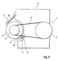
- the traction mechanism drive 1 is designed as a two-disc drive, in which a traction means 2, a driven member 3, a connected to a crankshaft of an internal combustion engine 4 belt pulley and another pulley of a drive member 5 connects.
- a pivotally mounted unit 6 in particular a starter generator is provided, which takes over the function of a generator for the internal combustion engine 4 depending on the operating mode in the starting phase, the function of the starter and the internal combustion engine 4.
- the unit 6 is pivotable about an axis of rotation 7 of a pivot bearing 8.
- the pivot bearing 8 comprises an integrally with the internal combustion engine 4 related holder 9 and associated holding means 10 of the unit 6.
- a pivoting of the unit 6 in the counterclockwise direction increases the bias of the traction means 2.
- the position of the pivot bearing 8 favors the bias of the traction means 2, there this utilizes the weight of the aggregate 6 to exert a counterclockwise force component.
- the unit 6, which takes over the function of a clamping system 11, is provided with a force means 12, in particular a spring inserted between the internal combustion engine 4 and the unit 6, with which the bias of the traction means 2 can be increased.
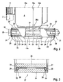
- the FIG. 1 shows a first pivot bearing 17a, which as a holding means 20a integrally with a housing 13 of the unit 6 connected fastening eyes 14, 15 and includes a holder 19a.
- the housing 13 of the unit 6 is formed from the two housing elements 16a, 16b, which are supported via a parting plane 18a.
- the parting plane 18a continues over the region of the fastening eyes 14, 15, so that by means of a machining of the respective housing element 16a, 16b including the associated fastening eyes 14 and 15 at the same time a support surface 21 is machined, on which the fastening eyes 14, 15 in support the installation position.
- the attachment eye 14 is further supported with a face remote from the support surface 21 end face directly on an end face of the holder 19 a, which together form a contact surface 22.
- the directly or indirectly connected to the engine 4 holder 19a is provided with a through hole 23 into which a socket 24 is inserted.
- a socket 24 is inserted into which a socket 24 is inserted.
- the sleeve 24 relative to the holder 19a is inserted in an annular gap which adjoins between the through hole 23 and a lateral surface of the sleeve 24, a sliding bearing 25.
- the bushing 24 by means of a fastening means, a screw 26 is frictionally supported on the mounting eye 14 and thus the holding means 20a.
- a desired rotation of the bushing 24 in the operating state with respect to the holder 19 a since the sleeve 24 rotatably connected to the holding means 20 a and thus the unit 6 is connected.
- the screw 26 is initially guided in a receiving bore 27 of the fastening eye 14 and further screwed into a threaded bore 28 of the fastening eye 15.
- a sealing ring 29 is provided, which seals a self-adjusting annular gap 30 between the holder 19 a and the sleeve 24.
- the end face of the sealing ring 28 is covered by a disc 31 which is inserted between a screw head 32 and the bush 24.
- the design of the pivot bearing 17a allows a shift in the direction of the traction means 2, whereby the force introduced by the traction means 2 in the unit 6 in the direction of arrow force direction triggers a reduced tilting moment in the pivot bearing 17a, which advantageously affects the load of the sliding bearing 25, whereby a increased life is feasible.
- two further embodiments shown are those with the first embodiment ( FIG. 1 ) Matching components provided with the same reference numerals, so that reference can be made to avoid repetition of the description of the first embodiment.
- FIG. 2 shows the pivot bearing 17b, which includes a U-shaped holder 19b, for example, a separate console, which is on the one hand releasably attached to the internal combustion engine 4 and two axially spaced receptacles 33, 34 includes. Between the receptacles 33, 34, the holding means 20a, consisting of the fastening eyes 14, 15 are used. The receptacles 33, 34 in conjunction with the sockets 24 inserted therein, according to the first embodiment allow a backlash-free arrangement. In the installed state, the sockets 24 are pressed by means of the screw 35 via the contact surfaces 22, 44 to the holding means 20a, the fastening eyes 14, 15.
- the structure of the floating bearing 37 illustrates the FIG. 3 ,
- the recording shown in an enlarged scale 34 shows the floating bearing 37 in the installed state, in which the design of the sleeve 24 ensures a projection 38 against a frontal contour 39 of the receptacle 34.
- the supernatant 38 which acts as an installation, effectively prevents the disc 31 from abutting the contour 39 of the receptacle 24, as a result of which the unit 6 can pivot freely in the operating state.
- FIG. 4 shows an embodiment with the pivot bearing 17c, which the holder 19a according to the embodiment of FIG. 1 includes as well as that Holding means 20b.
- the unit 6 is according to FIG. 4 provided with a parting plane 18 b, which is arranged offset in the direction of the traction means 2.
- This structure further advantageously reduces a transverse force, which is introduced by the traction means 2 in the arrow direction in the pivot bearing 17c, due to a reduced distance between the traction means 2 and the pivot bearing 17c,
- the retaining means 20b comprises only one fastening eye 40 integrally connected to the housing element 16b, the contact surface 42 of which extends in alignment with the parting plane 18a.
- the parting plane 18ab as well as the contact surface 42 can be processed inexpensively in one operation. Due to the relatively large width of the fastening eye 40, it makes sense to use as a fastener a self-tapping screw 41 which is self-tapping screwed into a partially prepared threaded hole 43 of the fastening eye 40, to achieve a fixed position support of the sleeve 24 via the contact surface 42 on the Fixing eye 40.
Landscapes
- Engineering & Computer Science (AREA)
- General Engineering & Computer Science (AREA)
- Power Engineering (AREA)
- Mechanical Engineering (AREA)
- Chemical & Material Sciences (AREA)
- Combustion & Propulsion (AREA)
- Connection Of Motors, Electrical Generators, Mechanical Devices, And The Like (AREA)
- Shafts, Cranks, Connecting Bars, And Related Bearings (AREA)
- Mounting Of Bearings Or Others (AREA)
- Devices For Conveying Motion By Means Of Endless Flexible Members (AREA)
Abstract
Claims (1)
- Organe d'un moteur à combustion interne (4), qui est réalisé à la fois comme système de serrage pour un moyen de traction (2) d'un entraînement à moyen de traction (1) et notamment en tant qu'alterno-démarreur, un boîtier (13) de l'organe (6) comprenant deux éléments de boîtier (16a, 16b) supportés l'un contre l'autre, qui forment un plan de séparation (18b), un élément de boîtier (16b) comportant un moyen de retenue (20b) qui est réalisé de manière à former avec au moins un support (9 ; 19a) disposé fixement, de préférence sur le moteur à combustion interne (4), un palier pivotant (8 ; 17c), et qui est formé à partir d'un oeillet de fixation (40) connecté d'une seule pièce à l'un des éléments de boîtier (16b), qui est supporté dans la position de montage par le biais d'une surface de contact (42) sur le support (19a) pour former le palier pivotant (8, 17c), caractérisé en ce que la surface de contact (42) s'étend en affleurement avec le plan de séparation (18b) des éléments de boîtier (16a, 16b), de sorte qu'un usinage simultané de l'un des éléments de boîtier (16b) dans la région du plan de séparation (18b) et de la surface de contact (42) soit possible.
Applications Claiming Priority (2)
| Application Number | Priority Date | Filing Date | Title |
|---|---|---|---|
| DE102004041044A DE102004041044A1 (de) | 2004-08-25 | 2004-08-25 | Drehpunktlagerung eines Aggregates |
| PCT/EP2005/008228 WO2006021287A1 (fr) | 2004-08-25 | 2005-07-29 | Logement a point d'appui d'un organe |
Publications (2)
| Publication Number | Publication Date |
|---|---|
| EP1781913A1 EP1781913A1 (fr) | 2007-05-09 |
| EP1781913B1 true EP1781913B1 (fr) | 2011-09-14 |
Family
ID=35345126
Family Applications (1)
| Application Number | Title | Priority Date | Filing Date |
|---|---|---|---|
| EP05782545A Expired - Fee Related EP1781913B1 (fr) | 2004-08-25 | 2005-07-29 | Logement a point d'appui d'un organe |
Country Status (6)
| Country | Link |
|---|---|
| US (1) | US20070259745A1 (fr) |
| EP (1) | EP1781913B1 (fr) |
| KR (1) | KR20070047791A (fr) |
| CN (1) | CN101006259A (fr) |
| DE (1) | DE102004041044A1 (fr) |
| WO (1) | WO2006021287A1 (fr) |
Families Citing this family (9)
| Publication number | Priority date | Publication date | Assignee | Title |
|---|---|---|---|---|
| JP4260066B2 (ja) * | 2004-05-31 | 2009-04-30 | 株式会社リコー | ベルト搬送装置及び画像形成装置 |
| US20080081718A1 (en) * | 2006-09-28 | 2008-04-03 | Collier-Hallman Steven J | Load dependent belt tensioner |
| SE541951C2 (sv) * | 2013-02-04 | 2020-01-14 | Scania Cv Ab | Länkarrangemang |
| JP6291683B2 (ja) * | 2014-03-18 | 2018-03-14 | サンデンホールディングス株式会社 | エンジン補機の取付装置 |
| CN105626261B (zh) * | 2016-02-18 | 2018-06-29 | 广西玉柴机器股份有限公司 | 一种多功能前端支撑架 |
| JP6414113B2 (ja) | 2016-03-24 | 2018-10-31 | 株式会社デンソー | 燃料供給装置 |
| FR3058772B1 (fr) * | 2016-11-16 | 2020-05-08 | Renault S.A.S. | Moteur equipe d'une liaison elastique pour tendre la courroie de transmission |
| DE102016226208A1 (de) * | 2016-12-23 | 2018-06-28 | Robert Bosch Gmbh | Verfahren zur Montage einer Maschine an einem Halteblock |
| JP7236940B2 (ja) * | 2019-06-04 | 2023-03-10 | ダイハツ工業株式会社 | 内燃機関 |
Family Cites Families (13)
| Publication number | Priority date | Publication date | Assignee | Title |
|---|---|---|---|---|
| US2856786A (en) * | 1955-09-21 | 1958-10-21 | Us Slicing Machine Co Inc | Belt tensioner for slicing machines |
| GB927186A (en) * | 1961-01-04 | 1963-05-29 | Cav Ltd | Means for mounting an electric generator on an engine |
| IT963768B (it) * | 1971-08-05 | 1974-01-21 | Bosch Gmbh Robert | Generatore di corrente alternata del tipo di costruzione a poli a denti frontali in particolare ge neratore trifase per veicoli |
| DE8915249U1 (fr) * | 1989-12-29 | 1991-04-25 | Robert Bosch Gmbh, 7000 Stuttgart, De | |
| US5098347A (en) * | 1990-09-26 | 1992-03-24 | Gates Power Drive Products, Inc. | Belt tensioner, belt drive sytstem, and method |
| DE4300178C1 (de) | 1993-01-07 | 1994-04-28 | Muhr & Bender | Riemenspannvorrichtung |
| JP3309882B2 (ja) | 1994-05-02 | 2002-07-29 | 株式会社デンソー | 発電機 |
| JP3186924B2 (ja) | 1994-05-30 | 2001-07-11 | 株式会社デンソー | 車両用交流発電機 |
| US5938169A (en) * | 1996-11-26 | 1999-08-17 | Suzuki Motor Corporation | Engine mounting for engine accessory |
| US6324744B1 (en) * | 2000-05-03 | 2001-12-04 | Daimlerchrysler Corporation | Method of mounting and axially aligning an engine accessory |
| DE10057818A1 (de) * | 2000-11-21 | 2002-05-23 | Ina Schaeffler Kg | Zugmitteltrieb für einen Startergenerator |
| US6450907B1 (en) * | 2001-03-12 | 2002-09-17 | The Gates Corporation | Inner race idler pulley tensioner |
| US6705581B2 (en) * | 2001-05-26 | 2004-03-16 | Pacsci Motion Control, Inc. | Pivotable motor mounting apparatus |
-
2004
- 2004-08-25 DE DE102004041044A patent/DE102004041044A1/de not_active Withdrawn
-
2005
- 2005-07-29 US US11/574,162 patent/US20070259745A1/en not_active Abandoned
- 2005-07-29 CN CNA200580028639XA patent/CN101006259A/zh active Pending
- 2005-07-29 KR KR1020077004259A patent/KR20070047791A/ko not_active Application Discontinuation
- 2005-07-29 WO PCT/EP2005/008228 patent/WO2006021287A1/fr active Application Filing
- 2005-07-29 EP EP05782545A patent/EP1781913B1/fr not_active Expired - Fee Related
Also Published As
| Publication number | Publication date |
|---|---|
| KR20070047791A (ko) | 2007-05-07 |
| WO2006021287A1 (fr) | 2006-03-02 |
| EP1781913A1 (fr) | 2007-05-09 |
| US20070259745A1 (en) | 2007-11-08 |
| DE102004041044A1 (de) | 2006-03-02 |
| CN101006259A (zh) | 2007-07-25 |
Similar Documents
| Publication | Publication Date | Title |
|---|---|---|
| EP1781913B1 (fr) | Logement a point d'appui d'un organe | |
| EP2612053B1 (fr) | Poulie de tension à excentrique | |
| DE10146612B4 (de) | Spannvorrichtung | |
| EP3431815B1 (fr) | Dispositif de tension de courroie | |
| EP1902235B1 (fr) | Joint pour bossage de support d'un systeme de serrage | |
| EP2573423A1 (fr) | Tendeur de courroie pour entrainement par courroie et arrangement de machine avec tendeur de courroie | |
| DE102007031298A1 (de) | Dämpfungsvorrichtung eines mechanischen Spannsystems für einen Zugmitteltrieb | |
| DE3546901C2 (de) | Automatische Riemenspannvorrichtung | |
| DE4223323C1 (en) | Mechanical belt or chain tensioning equipment - has hollow cylindrical body accommodating hub of jockey-roller eccentric and enclosed by radial flange supporting adjusting eccentric | |
| EP1604130B1 (fr) | Entrainement par mecanisme de traction | |
| DE10328900A1 (de) | Spannsystem mit einem Drechstab als Federmittel | |
| DE10105616A1 (de) | Spannvorrichtung | |
| DE10358376A1 (de) | Spannsystem für einen Zugmitteltrieb | |
| WO2005106287A1 (fr) | Systeme de tension pour mecanisme a elements de traction | |
| DE10021587A1 (de) | Spannvorrichtung für ein Zugmittel | |
| EP1604131B1 (fr) | Dispositif tendeur | |
| DE102005031294B4 (de) | Zugmitteltrieb eines Verbrennungskolbenmotors | |
| DE10230188A1 (de) | Spannsystem für einen Zugmitteltrieb | |
| WO2005052339A1 (fr) | Dispositif d'amortissement integre a un palier de pivotement | |
| DE10161534A1 (de) | Spannsystem für einen Zugmitteltrieb | |
| DE10344670A1 (de) | Vorrichtung zur schwenkbaren Lagerung eines Antriebsorgans | |
| DE10301758A1 (de) | Reibradantrieb | |
| DE102009021665A1 (de) | Riemenspannvorrichtung in einem Antriebsstrang eines Fahrzeugs und Verfahren zum Spannen eines Riemens | |
| DE102005004313A1 (de) | Vorrichtung zur Befestigung eines in einem Riementrieb drehbar gelagerten Aggregats | |
| DE3812375A1 (de) | Spannvorrichtung fuer einen antriebsriemen, eine antriebskette od. dgl. |
Legal Events
| Date | Code | Title | Description |
|---|---|---|---|
| PUAI | Public reference made under article 153(3) epc to a published international application that has entered the european phase |
Free format text: ORIGINAL CODE: 0009012 |
|
| 17P | Request for examination filed |
Effective date: 20070202 |
|
| AK | Designated contracting states |
Kind code of ref document: A1 Designated state(s): DE FR GB IT PL |
|
| DAX | Request for extension of the european patent (deleted) | ||
| RBV | Designated contracting states (corrected) |
Designated state(s): DE FR GB IT PL |
|
| 17Q | First examination report despatched |
Effective date: 20100224 |
|
| GRAP | Despatch of communication of intention to grant a patent |
Free format text: ORIGINAL CODE: EPIDOSNIGR1 |
|
| GRAS | Grant fee paid |
Free format text: ORIGINAL CODE: EPIDOSNIGR3 |
|
| GRAA | (expected) grant |
Free format text: ORIGINAL CODE: 0009210 |
|
| RAP1 | Party data changed (applicant data changed or rights of an application transferred) |
Owner name: SCHAEFFLER TECHNOLOGIES GMBH & CO. KG |
|
| AK | Designated contracting states |
Kind code of ref document: B1 Designated state(s): DE FR GB IT PL |
|
| REG | Reference to a national code |
Ref country code: GB Ref legal event code: FG4D Free format text: NOT ENGLISH |
|
| REG | Reference to a national code |
Ref country code: DE Ref legal event code: R096 Ref document number: 502005011890 Country of ref document: DE Effective date: 20111110 |
|
| RAP2 | Party data changed (patent owner data changed or rights of a patent transferred) |
Owner name: SCHAEFFLER TECHNOLOGIES AG & CO. KG |
|
| PG25 | Lapsed in a contracting state [announced via postgrant information from national office to epo] |
Ref country code: PL Free format text: LAPSE BECAUSE OF FAILURE TO SUBMIT A TRANSLATION OF THE DESCRIPTION OR TO PAY THE FEE WITHIN THE PRESCRIBED TIME-LIMIT Effective date: 20110914 Ref country code: IT Free format text: LAPSE BECAUSE OF FAILURE TO SUBMIT A TRANSLATION OF THE DESCRIPTION OR TO PAY THE FEE WITHIN THE PRESCRIBED TIME-LIMIT Effective date: 20110914 |
|
| REG | Reference to a national code |
Ref country code: DE Ref legal event code: R097 Ref document number: 502005011890 Country of ref document: DE |
|
| PLBE | No opposition filed within time limit |
Free format text: ORIGINAL CODE: 0009261 |
|
| STAA | Information on the status of an ep patent application or granted ep patent |
Free format text: STATUS: NO OPPOSITION FILED WITHIN TIME LIMIT |
|
| 26N | No opposition filed |
Effective date: 20120615 |
|
| REG | Reference to a national code |
Ref country code: DE Ref legal event code: R097 Ref document number: 502005011890 Country of ref document: DE Effective date: 20120615 |
|
| REG | Reference to a national code |
Ref country code: DE Ref legal event code: R081 Ref document number: 502005011890 Country of ref document: DE Owner name: SCHAEFFLER TECHNOLOGIES AG & CO. KG, DE Free format text: FORMER OWNER: SCHAEFFLER TECHNOLOGIES GMBH & CO. KG, 91074 HERZOGENAURACH, DE Effective date: 20120828 Ref country code: DE Ref legal event code: R081 Ref document number: 502005011890 Country of ref document: DE Owner name: SCHAEFFLER TECHNOLOGIES GMBH & CO. KG, DE Free format text: FORMER OWNER: SCHAEFFLER KG, 91074 HERZOGENAURACH, DE Effective date: 20110920 Ref country code: DE Ref legal event code: R081 Ref document number: 502005011890 Country of ref document: DE Owner name: SCHAEFFLER TECHNOLOGIES GMBH & CO. KG, DE Free format text: FORMER OWNER: SCHAEFFLER TECHNOLOGIES GMBH & CO. KG, 91074 HERZOGENAURACH, DE Effective date: 20120828 Ref country code: DE Ref legal event code: R081 Ref document number: 502005011890 Country of ref document: DE Owner name: SCHAEFFLER TECHNOLOGIES AG & CO. KG, DE Free format text: FORMER OWNER: SCHAEFFLER KG, 91074 HERZOGENAURACH, DE Effective date: 20110920 |
|
| GBPC | Gb: european patent ceased through non-payment of renewal fee |
Effective date: 20120729 |
|
| REG | Reference to a national code |
Ref country code: FR Ref legal event code: ST Effective date: 20130329 |
|
| PG25 | Lapsed in a contracting state [announced via postgrant information from national office to epo] |
Ref country code: GB Free format text: LAPSE BECAUSE OF NON-PAYMENT OF DUE FEES Effective date: 20120729 Ref country code: FR Free format text: LAPSE BECAUSE OF NON-PAYMENT OF DUE FEES Effective date: 20120731 |
|
| REG | Reference to a national code |
Ref country code: DE Ref legal event code: R081 Ref document number: 502005011890 Country of ref document: DE Owner name: SCHAEFFLER TECHNOLOGIES GMBH & CO. KG, DE Free format text: FORMER OWNER: SCHAEFFLER TECHNOLOGIES AG & CO. KG, 91074 HERZOGENAURACH, DE Effective date: 20140212 Ref country code: DE Ref legal event code: R081 Ref document number: 502005011890 Country of ref document: DE Owner name: SCHAEFFLER TECHNOLOGIES AG & CO. KG, DE Free format text: FORMER OWNER: SCHAEFFLER TECHNOLOGIES AG & CO. KG, 91074 HERZOGENAURACH, DE Effective date: 20140212 |
|
| PGFP | Annual fee paid to national office [announced via postgrant information from national office to epo] |
Ref country code: DE Payment date: 20140930 Year of fee payment: 10 |
|
| REG | Reference to a national code |
Ref country code: DE Ref legal event code: R081 Ref document number: 502005011890 Country of ref document: DE Owner name: SCHAEFFLER TECHNOLOGIES AG & CO. KG, DE Free format text: FORMER OWNER: SCHAEFFLER TECHNOLOGIES GMBH & CO. KG, 91074 HERZOGENAURACH, DE Effective date: 20150123 |
|
| REG | Reference to a national code |
Ref country code: DE Ref legal event code: R119 Ref document number: 502005011890 Country of ref document: DE |
|
| PG25 | Lapsed in a contracting state [announced via postgrant information from national office to epo] |
Ref country code: DE Free format text: LAPSE BECAUSE OF NON-PAYMENT OF DUE FEES Effective date: 20160202 |
|
| P01 | Opt-out of the competence of the unified patent court (upc) registered |
Effective date: 20230522 |