EP1781908B1 - Anordnung zur zuführung eines mediums in eine abgasleitung in einem verbrennungsmotor - Google Patents
Anordnung zur zuführung eines mediums in eine abgasleitung in einem verbrennungsmotor Download PDFInfo
- Publication number
- EP1781908B1 EP1781908B1 EP05733731A EP05733731A EP1781908B1 EP 1781908 B1 EP1781908 B1 EP 1781908B1 EP 05733731 A EP05733731 A EP 05733731A EP 05733731 A EP05733731 A EP 05733731A EP 1781908 B1 EP1781908 B1 EP 1781908B1
- Authority
- EP
- European Patent Office
- Prior art keywords
- exhaust
- urea solution
- exhaust passage
- wall surface
- nozzle
- Prior art date
- Legal status (The legal status is an assumption and is not a legal conclusion. Google has not performed a legal analysis and makes no representation as to the accuracy of the status listed.)
- Expired - Lifetime
Links
Images


Classifications
-
- F—MECHANICAL ENGINEERING; LIGHTING; HEATING; WEAPONS; BLASTING
- F01—MACHINES OR ENGINES IN GENERAL; ENGINE PLANTS IN GENERAL; STEAM ENGINES
- F01N—GAS-FLOW SILENCERS OR EXHAUST APPARATUS FOR MACHINES OR ENGINES IN GENERAL; GAS-FLOW SILENCERS OR EXHAUST APPARATUS FOR INTERNAL-COMBUSTION ENGINES
- F01N3/00—Exhaust or silencing apparatus having means for purifying, rendering innocuous, or otherwise treating exhaust
- F01N3/08—Exhaust or silencing apparatus having means for purifying, rendering innocuous, or otherwise treating exhaust for rendering innocuous
- F01N3/10—Exhaust or silencing apparatus having means for purifying, rendering innocuous, or otherwise treating exhaust for rendering innocuous by thermal or catalytic conversion of noxious components of exhaust
- F01N3/18—Exhaust or silencing apparatus having means for purifying, rendering innocuous, or otherwise treating exhaust for rendering innocuous by thermal or catalytic conversion of noxious components of exhaust characterised by methods of operation; Control
- F01N3/20—Exhaust or silencing apparatus having means for purifying, rendering innocuous, or otherwise treating exhaust for rendering innocuous by thermal or catalytic conversion of noxious components of exhaust characterised by methods of operation; Control specially adapted for catalytic conversion
- F01N3/206—Adding periodically or continuously substances to exhaust gases for promoting purification, e.g. catalytic material in liquid form, NOx reducing agents
- F01N3/2066—Selective catalytic reduction [SCR]
-
- F—MECHANICAL ENGINEERING; LIGHTING; HEATING; WEAPONS; BLASTING
- F01—MACHINES OR ENGINES IN GENERAL; ENGINE PLANTS IN GENERAL; STEAM ENGINES
- F01N—GAS-FLOW SILENCERS OR EXHAUST APPARATUS FOR MACHINES OR ENGINES IN GENERAL; GAS-FLOW SILENCERS OR EXHAUST APPARATUS FOR INTERNAL-COMBUSTION ENGINES
- F01N3/00—Exhaust or silencing apparatus having means for purifying, rendering innocuous, or otherwise treating exhaust
- F01N3/08—Exhaust or silencing apparatus having means for purifying, rendering innocuous, or otherwise treating exhaust for rendering innocuous
- F01N3/10—Exhaust or silencing apparatus having means for purifying, rendering innocuous, or otherwise treating exhaust for rendering innocuous by thermal or catalytic conversion of noxious components of exhaust
- F01N3/18—Exhaust or silencing apparatus having means for purifying, rendering innocuous, or otherwise treating exhaust for rendering innocuous by thermal or catalytic conversion of noxious components of exhaust characterised by methods of operation; Control
- F01N3/20—Exhaust or silencing apparatus having means for purifying, rendering innocuous, or otherwise treating exhaust for rendering innocuous by thermal or catalytic conversion of noxious components of exhaust characterised by methods of operation; Control specially adapted for catalytic conversion
- F01N3/206—Adding periodically or continuously substances to exhaust gases for promoting purification, e.g. catalytic material in liquid form, NOx reducing agents
-
- B—PERFORMING OPERATIONS; TRANSPORTING
- B01—PHYSICAL OR CHEMICAL PROCESSES OR APPARATUS IN GENERAL
- B01F—MIXING, e.g. DISSOLVING, EMULSIFYING OR DISPERSING
- B01F23/00—Mixing according to the phases to be mixed, e.g. dispersing or emulsifying
- B01F23/20—Mixing gases with liquids
- B01F23/21—Mixing gases with liquids by introducing liquids into gaseous media
- B01F23/213—Mixing gases with liquids by introducing liquids into gaseous media by spraying or atomising of the liquids
- B01F23/2132—Mixing gases with liquids by introducing liquids into gaseous media by spraying or atomising of the liquids using nozzles
-
- B—PERFORMING OPERATIONS; TRANSPORTING
- B01—PHYSICAL OR CHEMICAL PROCESSES OR APPARATUS IN GENERAL
- B01F—MIXING, e.g. DISSOLVING, EMULSIFYING OR DISPERSING
- B01F25/00—Flow mixers; Mixers for falling materials, e.g. solid particles
- B01F25/40—Static mixers
- B01F25/42—Static mixers in which the mixing is affected by moving the components jointly in changing directions, e.g. in tubes provided with baffles or obstructions
- B01F25/43—Mixing tubes, e.g. wherein the material is moved in a radial or partly reversed direction
- B01F25/432—Mixing tubes, e.g. wherein the material is moved in a radial or partly reversed direction with means for dividing the material flow into separate sub-flows and for repositioning and recombining these sub-flows; Cross-mixing, e.g. conducting the outer layer of the material nearer to the axis of the tube or vice-versa
- B01F25/4323—Mixing tubes, e.g. wherein the material is moved in a radial or partly reversed direction with means for dividing the material flow into separate sub-flows and for repositioning and recombining these sub-flows; Cross-mixing, e.g. conducting the outer layer of the material nearer to the axis of the tube or vice-versa using elements provided with a plurality of channels or using a plurality of tubes which can either be placed between common spaces or collectors
-
- F—MECHANICAL ENGINEERING; LIGHTING; HEATING; WEAPONS; BLASTING
- F01—MACHINES OR ENGINES IN GENERAL; ENGINE PLANTS IN GENERAL; STEAM ENGINES
- F01N—GAS-FLOW SILENCERS OR EXHAUST APPARATUS FOR MACHINES OR ENGINES IN GENERAL; GAS-FLOW SILENCERS OR EXHAUST APPARATUS FOR INTERNAL-COMBUSTION ENGINES
- F01N1/00—Silencing apparatus characterised by method of silencing
- F01N1/08—Silencing apparatus characterised by method of silencing by reducing exhaust energy by throttling or whirling
- F01N1/084—Silencing apparatus characterised by method of silencing by reducing exhaust energy by throttling or whirling the exhaust gases flowing through the silencer two or more times longitudinally in opposite directions, e.g. using parallel or concentric tubes
-
- F—MECHANICAL ENGINEERING; LIGHTING; HEATING; WEAPONS; BLASTING
- F01—MACHINES OR ENGINES IN GENERAL; ENGINE PLANTS IN GENERAL; STEAM ENGINES
- F01N—GAS-FLOW SILENCERS OR EXHAUST APPARATUS FOR MACHINES OR ENGINES IN GENERAL; GAS-FLOW SILENCERS OR EXHAUST APPARATUS FOR INTERNAL-COMBUSTION ENGINES
- F01N1/00—Silencing apparatus characterised by method of silencing
- F01N1/08—Silencing apparatus characterised by method of silencing by reducing exhaust energy by throttling or whirling
- F01N1/12—Silencing apparatus characterised by method of silencing by reducing exhaust energy by throttling or whirling using spirally or helically shaped channels
-
- F—MECHANICAL ENGINEERING; LIGHTING; HEATING; WEAPONS; BLASTING
- F01—MACHINES OR ENGINES IN GENERAL; ENGINE PLANTS IN GENERAL; STEAM ENGINES
- F01N—GAS-FLOW SILENCERS OR EXHAUST APPARATUS FOR MACHINES OR ENGINES IN GENERAL; GAS-FLOW SILENCERS OR EXHAUST APPARATUS FOR INTERNAL-COMBUSTION ENGINES
- F01N13/00—Exhaust or silencing apparatus characterised by constructional features
- F01N13/009—Exhaust or silencing apparatus characterised by constructional features having two or more separate purifying devices arranged in series
- F01N13/0097—Exhaust or silencing apparatus characterised by constructional features having two or more separate purifying devices arranged in series the purifying devices are arranged in a single housing
-
- F—MECHANICAL ENGINEERING; LIGHTING; HEATING; WEAPONS; BLASTING
- F01—MACHINES OR ENGINES IN GENERAL; ENGINE PLANTS IN GENERAL; STEAM ENGINES
- F01N—GAS-FLOW SILENCERS OR EXHAUST APPARATUS FOR MACHINES OR ENGINES IN GENERAL; GAS-FLOW SILENCERS OR EXHAUST APPARATUS FOR INTERNAL-COMBUSTION ENGINES
- F01N2470/00—Structure or shape of exhaust gas passages, pipes or tubes
- F01N2470/24—Concentric tubes or tubes being concentric to housing, e.g. telescopically assembled
-
- F—MECHANICAL ENGINEERING; LIGHTING; HEATING; WEAPONS; BLASTING
- F01—MACHINES OR ENGINES IN GENERAL; ENGINE PLANTS IN GENERAL; STEAM ENGINES
- F01N—GAS-FLOW SILENCERS OR EXHAUST APPARATUS FOR MACHINES OR ENGINES IN GENERAL; GAS-FLOW SILENCERS OR EXHAUST APPARATUS FOR INTERNAL-COMBUSTION ENGINES
- F01N2610/00—Adding substances to exhaust gases
- F01N2610/02—Adding substances to exhaust gases the substance being ammonia or urea
-
- F—MECHANICAL ENGINEERING; LIGHTING; HEATING; WEAPONS; BLASTING
- F01—MACHINES OR ENGINES IN GENERAL; ENGINE PLANTS IN GENERAL; STEAM ENGINES
- F01N—GAS-FLOW SILENCERS OR EXHAUST APPARATUS FOR MACHINES OR ENGINES IN GENERAL; GAS-FLOW SILENCERS OR EXHAUST APPARATUS FOR INTERNAL-COMBUSTION ENGINES
- F01N2610/00—Adding substances to exhaust gases
- F01N2610/10—Adding substances to exhaust gases the substance being heated, e.g. by heating tank or supply line of the added substance
- F01N2610/102—Adding substances to exhaust gases the substance being heated, e.g. by heating tank or supply line of the added substance after addition to exhaust gases, e.g. by a passively or actively heated surface in the exhaust conduit
-
- Y—GENERAL TAGGING OF NEW TECHNOLOGICAL DEVELOPMENTS; GENERAL TAGGING OF CROSS-SECTIONAL TECHNOLOGIES SPANNING OVER SEVERAL SECTIONS OF THE IPC; TECHNICAL SUBJECTS COVERED BY FORMER USPC CROSS-REFERENCE ART COLLECTIONS [XRACs] AND DIGESTS
- Y02—TECHNOLOGIES OR APPLICATIONS FOR MITIGATION OR ADAPTATION AGAINST CLIMATE CHANGE
- Y02T—CLIMATE CHANGE MITIGATION TECHNOLOGIES RELATED TO TRANSPORTATION
- Y02T10/00—Road transport of goods or passengers
- Y02T10/10—Internal combustion engine [ICE] based vehicles
- Y02T10/12—Improving ICE efficiencies
Definitions
- the invention relates to an arrangement for supplying a urea solution to an exhaust line of a combustion engine according to the preamble of claim 1.
- a technique known as SCR selective catalytic reduction
- SCR selective catalytic reduction
- This technique involves adding a solution of urea in a specified dose to the exhaust gases in the exhaust line of a diesel engine.
- the urea solution may be sprayed into the exhaust line in such a way that it is finely divided, after which the urea solution in contact with the hot exhaust gases vaporises and ammonia is formed.
- the mixture of ammonia and exhaust gases is led thereafter through a catalyst in which a chemical reaction takes place.
- the nitrogen of the nitrogen oxides in the exhaust gases reacts here with the nitrogen in the ammonia, with the result that nitrogen gas is formed.
- the oxygen of the nitrogen oxides reacts with the hydrogen in the ammonia, with the result that water is formed.
- the nitrogen oxides in the exhaust gases are thus reduced in the catalyst to nitrogen gas and water vapour. Correct dosage of urea enables the diesel engine's discharge of nitrogen oxides to be to a great extent reduced.
- the exhaust gases are at a sufficiently high temperature to vaporise the urea solution so that ammonia is formed. It is difficult, however, to prevent some of the urea supplied from coming into contact with and becoming attached to the inside wall surface of the exhaust line in an unvaporised state.
- the exhaust line of a vehicle is usually in contact with ambient air.
- the exhaust line is cooled by ambient air to a lower temperature than that of the exhaust gases inside the exhaust line. In most cases, however, the exhaust line is at a sufficiently high temperature to vaporise and convert to ammonia the urea solution which comes into contact with the inside wall surface of the exhaust line.
- urea solution will accumulate on the inside wall surface of the exhaust line.
- the urea solution may crystallise on the inside of the exhaust line or leak out via joints of the exhaust line and crystallise on the outside of the exhaust line. This may lead to malfunctions.
- EP-A1- 1054139 discloses a system for the injection of reducing agent to an exhaust gas pipe. Efficient evaporation is obtained by utilizing a heated plate.
- JP-A- 2002306929 discloses a device for cleaning exhaust gas, which device prevents fused solidification of urea when the urea is supplied to the system.
- the engine gas is introduced into an evaporation part and the urea solution is heated up by the heat from the exhaust gas.
- US-B2- 6601 385 discloses a SCR System with an inertial impactor for efficient urea solution evaporation.
- the impactor can be a plate, a porous member, a bowl or a flow through catalyst.
- the impactor can be connected to a heat source.
- US-A1- 20020187093 discloses a process for catalytic cleaning of exhaust gas.
- a reducing agent such as urea
- the exhaust gas stream is then deflected into a reaction duct which extends parallel to or coaxially around the conversion duct.
- the described construction minimizes heat losses by substantial reduction of outer surface.
- the catalyst 36 can be interpreted as the source of heat and the opposite flow direction can be interpreted as the second exhaust gas passage.
- EP-Al- 0896831 discloses a system for catalytic reduction of nitrogen oxides with urea.
- a vaporizer with a hydrolysis catalyst coating is used to increase the effective temperature range and thermal stability.
- the injection of urea is performed into a heated section.
- DE-A1- 19913462 discloses a process for hydrolyzing urea to generate ammonia for reducing nitrogen oxides in an SCR exhaust system.
- the process comprises withdrawing a side stream of exhaust gas from an exhaust pipe upstream the catalytic converter.
- the side stream is mixed with the urea and it can be heated from external exhaust gas stream surrounding the side stream.
- JP-A- 8192028 relates to a method for introducing a reducing agent into an exhaust gas flow.
- the exhaust gas flow path is surrounded by insulated walls.
- WO-Al- 9739226 describes an injector for injecting reducing agent into an exhaust pipe.
- the injector is provided with a plurality of openings facing upstream, downstream and in opposite sideward directions whereby an efficient mixing of reducing agent with exhaust gas is achieved.
- WO-A1- 0229219 discloses a SCR catalytic converter system with injection of urea into the exhaust gas flow. By introducing the urea into a part with walls including protuberances and indentations an improved formation of a mixture of reducing agent and exhaust gas is attained, and also a more compact system.
- the object of the present invention is to provide an arrangement which supplies a urea solution to an exhaust line of a combustion engine whereby the urea solution supplied is substantially certain to vaporise completely in the exhaust line even if the urea solution in liquid form reaches the inside wall surface of the exhaust line.
- the arrangement comprises means adapted to maintaining a degree of heating of the first wall surface so that it will be at a higher temperature than the urea solution's vaporisation point when the liquid urea solution is supplied in the first exhaust passage.
- the first wall surface will thus be at a higher temperature than the urea solution in liquid form which reaches the first wall surface.
- said means comprises a heat source which supplies heat to the first wall surface.
- the first wall surface can therefore, at least when necessary, be heated so that it is substantially continuously at a temperature higher than the urea solution's vaporisation point.
- the heat source may be an electrical heating element which supplies thermal energy to the first wall surface according to the latter's prevailing temperature.
- said heat source comprises a second exhaust passage bounded by a second wall surface situated close to the first wall surface. The temperature of the exhaust gases is usually definitely higher than the urea solution's vaporisation point. It is therefore advantageous to utilise the existing thermal energy of the exhaust gases as the heat source.
- Leading exhaust gases through a second passage close to the first passage is a simple way of providing heat transfer to the first wall surface from the exhaust gases in the second exhaust passage.
- An element made of a material with good heat conducting properties will result in little resistance to the passing of thermal energy from the second wall surface to the first wall surface.
- the first wall surface will thus substantially continuously maintain a temperature corresponding to at least the urea solution's vaporisation point.
- said element is a wall element applied in a spiral exhaust line and dividing a portion of the exhaust line into a first exhaust passage and a second exhaust passage.
- a spiral exhaust line is compact and heat transfer between adjoining radial portions of the exhaust line is not complicated.
- the sidewalls of a spiral exhaust line are usually in contact with ambient air.
- the first exhaust passage can be provided with sidewall surfaces heated by surrounding exhaust gases. The first passage can therefore be so arranged as to be completely surrounded by inside wall surfaces which are heated by surrounding exhaust gases.
- the dosing device comprises a spray nozzle by which the urea solution is sprayed into said first exhaust passage.
- a spray nozzle results in very fine division of the liquid urea solution being sprayed into the tubular element. The result is rapid and effective vaporisation of the urea solution when it mixes with the exhaust gases flowing through the tubular element.
- the exhaust line contains a catalyst.
- SCR selective catalytic reduction
- a urea solution can be used for providing ammonia, which is a necessary substance for effecting a chemical reaction whereby the nitrogen oxides in the exhaust gases are reduced to nitrogen gas and water vapour.
- a urea solution is easy to handle and store because it is both relatively odourless and non-toxic. Supplying the urea solution in well-defined doses enables the diesel engine's discharge of nitrogen oxides to be considerably reduced.
- the present invention makes it possible for an optimum supply of urea to be provided, with the result that all the urea solution supplied is certain to vaporise. It is also possible with the present invention to supply other media than urea to the exhaust line.
- said element is tubular and is fitted in such a position inside the exhaust line that the first passage is provided inside the tubular element, and the second exhaust passage is provided between the outside wall surface of the tubular element and an inside wall surface of the exhaust line.
- the inside wall surface of the tubular element constitutes the first wall surface
- the outside surface of the tubular element constitutes the second wall surface.
- the exhaust gases in the exhaust line thus flow along both the inside and the outside of the tubular element.
- the tubular element is entirely surrounded by gases, the whole tubular element will be at substantially the same temperature as the exhaust gases in the exhaust line.
- the inside wall surface of the tubular element will therefore also be at substantially the same temperature as the exhaust line.
- the tubular element is preferably relatively thin and made of a metal material with good heat conducting properties. With advantage, the tubular element is fitted in a central position in the exhaust line. The result will be uniform flow of exhaust gases in the second exhaust passage round the tubular element.
- the tubular element may be applied in a substantially straight portion of an exhaust line, but it is possible for the tubular element to be situated in exhaust line sections of substantially any desired shape.
- the element constitutes an integral part of the exhaust line and said means comprises a thermally insulating material applied between the first wall surface and an environment.
- the element is shaped like the exhaust line but may be made of a material with considerably higher thermally insulating properties than the exhaust line elsewhere.
- a suitable insulating material of appropriate thickness may be applied round the outside surface of the element. With such a thermally insulating material, the cooling action of the environment on the inside wall surface can be substantially eliminated.
- the inside wall surface of the element will then only be heated by the exhaust gases flowing through the first exhaust passage, but this heat supply is usually amply sufficient to cause the urea solution in liquid form which reaches the inside wall surface to vaporise, since the cooling action of the environment on the first wall surface has been eliminated.
- the inside wall surface of the element comprises at least one region with an uneven surface.
- the result is that in that region the tubular element has a larger inside wall surface than in the case of an even surface.
- An uneven wall surface detains liquid urea solution until it vaporises.
- the inside wall surface of the element may comprise at least one recess which has an extent in a direction substantially perpendicular to the direction of flow of the exhaust gases in the first exhaust passage. The liquid urea solution is thus effectively detained in the recess until it vaporises.
- Such recesses at suitable locations make it possible for the element to be of reduced length.
- said nozzle comprises a plurality of radial apertures which lead the urea solution in the first exhaust passage in directions substantially perpendicular to the main direction of flow of the exhaust gases in the first exhaust passage.
- the liquid urea solution thus meets the exhaust flow in such a way that a large proportion of the urea solution is entrained by the flowing exhaust gases and vaporises before it reaches an inside wall surface of the first exhaust passage.
- Said nozzle may be applied in a curved first exhaust passage situated in a portion of a spiral exhaust line which extends about a central axis, whereby the positioning of the nozzle apertures is such that the urea solution is supplied in directions which predominantly lead the urea solution radially inwards towards said central axis in the curved first exhaust passage.
- a liquid urea solution which is heavier than the exhaust gases and is flung radially outwards by centrifugal force in a curved exhaust passage may well result in a relatively large proportion of the urea solution supplied accumulating on a radially outside wall surface of the exhaust passage.
- the first exhaust passage is bounded in an axial direction relative to said central axis by two wall elements situated at a distance from one another, and in a radial direction relative to said central axis by an outer wall element and an inner wall element, whereby the nozzle is adapted to supplying the urea solution in at least one direction towards each of the axial wall elements and the radial inner wall element, but not in any direction towards the radial outer wall element.
- Suitable distribution of the nozzle apertures enables the urea solution to be supplied substantially uniformly to the axial wall elements and the radial inner wall element.
- the radial outer wall element may also receive a corresponding amount of the urea solution when the liquid urea solution supplied is led radially outwards by centrifugal force in the curved exhaust passage.
- the nozzle is fitted in the first exhaust passage at a position situated closer to the radial outer wall element than the radial inner wall element.
- the distance between the nozzle apertures and their intended liquid contact areas on inside surfaces of the exhaust passage is thereby increased. Increasing this distance enables a larger proportion of the amount of urea solution supplied to be entrained by and vaporised in the exhaust flow before it reaches an inside surface of the exhaust passage.
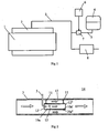
- Fig. 1 depicts a combustion engine in the form of a diesel engine 1.
- the diesel engine 1 may for example be intended to power a heavy vehicle.
- the exhaust gases from the cylinders of the diesel engine 1 are led via an exhaust manifold 2 to an exhaust line 3.
- the exhaust line 3 is provided with an arrangement which effects catalytic exhaust cleaning according to the method known as SCR (selective catalytic reduction).
- SCR selective catalytic reduction
- This method entails a urea solution being added to the exhaust gases in the diesel engine's exhaust line 3.
- the urea solution is stored in a tank 4 and is led via a line 5 to the exhaust line 3.
- a control unit 6, which may be a computer unit with suitable software, controls the supply of the urea solution which is led to the exhaust line 3 by activating a pump 7.
- the control unit 6 may use information concerning current fuel consumption and the temperature of the exhaust gases to calculate the amount of urea solution which needs to be added for optimum reduction of the nitrogen oxides content of the exhaust gases.
- the urea solution supplied is intended to be heated by the exhaust gases in the exhaust line 3 so that it vaporises and converts to ammonia.
- the mixture of ammonia and exhaust gases is thereafter led on through the exhaust line 3 to a catalyst 8 in which a chemical reaction takes place.
- the nitrogen of the nitrogen oxides in the exhaust gases reacts here with the nitrogen in the ammonia, with the result that nitrogen gas is formed.
- the oxygen of the nitrogen oxides reacts with the hydrogen in the ammonia, with the result that water is formed.
- the nitrogen oxides in the exhaust gases are thus reduced in the catalyst 8 to nitrogen gas and water vapour which are led out to ambient air.
- Fig. 2 depicts an arrangement for supplying urea solution to the exhaust line 3.
- the line 5 intended to carry the urea solution extends here through an aperture in a wall of the exhaust line 3.
- the line 5 has a curved end portion to which a spray nozzle 9 is fastened.
- a tubular element 10a narrower than the exhaust line 3 is fitted by suitable fastening means 11 in a substantially central position inside the exhaust line 3.
- the exhaust gases flow in the direction of the arrows inside the exhaust line 3.
- the tubular element 10a has an inside wall surface 10a' which defines a first passage 12 for the exhaust gases.
- the first exhaust passage 12 extends between an inlet 12' and an outlet 12".
- urea solution is sprayed by the spray nozzle 9 into the first exhaust passage 12 close to the latter's inlet 12'.
- the urea solution added will thus be entrained by the exhaust flow through substantially the whole of the first exhaust passage 12.
- a second exhaust passage 13 is constituted radially about the outside of the tubular element 10a.
- the second exhaust passage 13 has a radial extent between an outside wall surface 10a" of the tubular element 10a and an inside wall surface of the exhaust line 3. The exhaust gases in the exhaust line 3 will thus flow in parallel through the first exhaust passage 12 and the second exhaust passage 13.
- the tubular element's outside wall surface 10a" is therefore in contact with the exhaust gases flowing through the second exhaust passage 13.
- the tubular element's outside wall surface 10a" will thus maintain a temperature substantially corresponding to that of the exhaust gases.
- the tubular element 10a has with advantage relatively thin walls and is with advantage made of a material with good heat conducting properties. Heat can thus quickly be transferred from the outside wall surface 10a" to the inside wall surface 1 0a' when there is a temperature difference between these surfaces. Such a temperature difference may temporarily occur when urea solution vaporises on the inside wall surface 10a', since this vaporisation process consumes a good deal of thermal energy.
- the supply of heat from the second exhaust passage 13 nevertheless keeps the inside wall surface 10a' at a temperature which exceeds the urea solution's vaporisation point.
- urea solution When exhaust gases flow through the exhaust line 3, urea solution is sprayed into the first exhaust passage 12 inside the tubular element 10a via the spray nozzle 9 in a dose calculated by the control unit 6.
- the urea solution has a vaporisation point which in normal circumstances is lower than the temperature of the exhaust gases but higher than the temperature of the environment 14.
- the urea solution finely divided via the spray nozzle 9 mixes with the exhaust gases flowing through the first exhaust passage 12.
- the hot exhaust gases heat the finely divided urea solution so that it vaporises and forms ammonia.
- some of the liquid urea solution is not vaporised by the exhaust gases before it reaches the inside wall surface 10a'.
- the inside wall surface 10a' maintains a higher temperature than the urea solution's vaporisation point.
- a suitably dimensioned tubular element 10a makes it possible for substantially all the urea solution supplied in the first exhaust passage 12 to vaporise and form ammonia in the first exhaust passage 12.
- the tubular element 10a may for example be 100 to 200 mm long with a diameter of 80 to 100 mm, but its dimensions have also to be adapted according to the dimensions of the exhaust line 3.
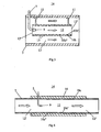
- Fig. 3 depicts an alternative arrangement for supplying a urea solution to an exhaust line 3.
- This arrangement differs from the arrangement in Fig. 2 in that the tubular element 10b depicted here has an inside wall surface 10b' which comprises a plurality of annular recesses 15 which extend in a direction substantially perpendicular to the direction of flow of the exhaust gases through the first exhaust passage 12.
- the tubular element 10b has an even outside wall surface 10b".
- Urea solution which reaches the inside wall surface 10b' will accumulate in said recesses 15 until the urea solution vaporises.
- Such recesses 15 prevent any certainty of the urea solution being entrained by the exhaust gas flow through the first exhaust passage 12 and out through the outlet 12" before it vaporises.
- the tubular element 10b may in this case be of reduced length as compared with a tubular element 10a which has an even inside wall surface 10a".
- Fig. 4 depicts a further arrangement for supplying a urea solution to an exhaust line 3.
- a tubular element 10c which constitutes an integral part of the exhaust line 3 is used.
- the shape and size of the tubular element 10c correspond to those of the exhaust line 3.
- a thermally insulating material 16 is applied externally round the outside wall surface 10c" of the tubular element 10c.
- Other portions of the exhaust line 3 may possibly also be provided wholly or partly with thermally insulating material.
- the thermally insulating material 16 prevents the inside wall surface 10c' of the tubular element being cooled down by ambient air, which is usually at a definitely lower temperature than the urea solution's vaporisation point.
- Suitable choice and suitable thickness of the insulating material 16 will enable the cooling action of the environment 14 upon the tubular element's inside wall surface 10c' to be substantially eliminated.
- the tubular element 10c constitutes a gas passage 12 through which all the exhaust gases in the exhaust line 3 flow.
- the exhaust gases heat the inside wall surface 10c' of the tubular element 10c.
- the inside wall surface 10c' can maintain a temperature at least corresponding to the urea solution's vaporisation point.
- urea solution is sprayed into the first exhaust passage 12 close to the inlet 12'.
- the exhaust gases heat the finely divided urea solution so that it vaporises and forms ammonia.
- the urea solution which reaches the inside wall surface 10c' is subjected to heating by the inside wall surface 10c' until it vaporises.
- the length of the tubular element 10c is such that substantially all the urea supplied vaporises inside the tubular element 10c.
- Fig. 5 depicts a container 17 in the form of a combined silencer and exhaust cleaner intended to be applied in an exhaust system for a diesel-powered vehicle.
- the container 17 comprises an external housing 18 which is of substantially circular cylindrical shape.
- the housing 18 constitutes a closed outside wall surface except at the points where an inlet 19 and an outlet 20 are provided for the exhaust gases.
- a circular pipe 21 is arranged inside the housing 18. The length of the pipe 21 is such that it extends from a first endwall 18a of the housing to a module 22 which comprises a second endwall 18b of the housing.
- the container device 17 comprises an exhaust line 3 which extends from the inlet 19 to the outlet 20.
- the exhaust line comprises after the inlet 19 a first exhaust line section 3a which has a substantially straight extent about the outside of the pipe 21 from the inlet 19 to the module 22.
- a particle filter 23 is arranged in the first exhaust line section 3a. When the exhaust gases pass through the particle filter 23, the soot particles in the exhaust gases are caught in the particle filter 23 and thereafter burn therein.
- the exhaust gases cleaned of soot particles are thereafter led into the module 22 which comprises a wall element 24.
- the wall surfaces of the wall element 24 define a second exhaust line section 3b which extends about a central axis c.
- the lateral extent of the spiral second exhaust line section is bounded by the second endwall 18b and a wall element 25 of the module 22.
- the spiral element 24 and the wall element 25 have wall surfaces which on both sides are in contact with exhaust gases, but the outside wall surface of the endwall 18b is in contact with ambient air 14.
- An extra wall element 10d is arranged in part of the spiral exhaust line section 3b.
- the extra wall element 10d divides that portion of the spiral exhaust line 3b into a first gas passage 12 and a second gas passage 13.
- the first exhaust passage 12 is bounded laterally by the extra wall element 10d.
- the extra wall element 10d has wall surfaces which on both sides are surrounded by exhaust gases.
- the first exhaust passage 12 will therefore be bounded in an axial direction relative to said central axis c by the wall elements 25, 10d which have wall surfaces which on both sides are surrounded by exhaust gases.
- the first exhaust passage 12 is bounded in a radial direction relative to said central axis c by a radially inner portion of the spiral wall element 24 i and a radially outer portion of the spiral wall element 24 u , which are thus also surrounded by exhaust gases on both sides (see Fig. 7 ).
- the urea solution is sprayed by the spray nozzle 9 into the first exhaust passage 12 close to the latter's inlet 12' (see Fig. 6 ).
- the urea solution added therefore mixes with the exhaust gases in the first exhaust passage 12.
- the first exhaust passage 12 is bounded by inside wall surfaces 24 i ', 24 u ', 25', 10d' of the wall elements 24 i , 24 u , 25, 10d, which have outside wall surfaces 24 i ", 24 u ", 25", 10d” heated by surrounding exhaust gases.
- Outside wall surfaces means the surfaces of the wall elements 24 i , 24 u , 25, 10d which are situated on the opposite side of the inside surfaces 24 i ', 24 u ', 25', 10d'.
- the portion of the urea solution supplied which is carried by the exhaust gas flow into the first exhaust passage 12 is heated by the exhaust gases so that it vaporises and converts to ammonia.
- the portion of urea solution which reaches the inside wall surfaces 24 i ', 24 u ', 25', 10d' is heated by the inside wall surfaces 24 i ', 24 u ', 25', 10d' which are supplied with heat from surrounding exhaust gases.
- the inside wall surfaces 24 i ', 24 u ', 25', 10d' are thus provided with a temperature which exceeds the urea solution's vaporisation point.
- the urea solution which reaches the inside wall surfaces 24 i ', 24 u ' , 25', 10d' will therefore substantially always vaporise and convert to ammonia.
- the nozzle 9 has eight radial apertures 26a-h which spray urea solution in eight different directions 27a-h in the first exhaust passage 12.
- the nozzle 9 has a first row of four apertures 26a-d depicted in Fig. 9 and a second row of four apertures 26e-h depicted in Fig. 10 .
- Two of the nozzle's apertures 26a, e are directed in such a way that the urea solution is sprayed in the directions 27a, e towards the inside surface 10d' of the extra wall element 10d.
- nozzle's apertures 26b, c, f, g are directed in such a way that the urea solution is sprayed in the directions 27b, c, f, g towards the inside surface 24 i ' of the radially inner portion of the spiral element.
- Two of the nozzle's apertures 26d, h are directed in such a way that the urea solution is sprayed in the directions 27d, h towards the inside wall surface 25' of the wall element 25.
- none of the nozzle's apertures 26a-h are directed in such a way that the urea solution is sprayed towards the radially outer portion 24 u of the spiral element.
- the directions 27a-h are chosen such that the portion of the urea solution which is not entrained by the exhaust flow reaches these inside surfaces 24 i ', 25', 10d' with a substantially uniform distribution.
- the nozzle 9 has no aperture directed towards the radially outer portion 24 u of the spiral element, some of the urea solution supplied may still reach its inside surface 24 u ' as a result of centrifugal force.
- Figs. 9 and 10 show examples of suitable angular spacing between the apertures 26a-h in the two rows mentioned.
- the apertures 26a-h are here distributed over an angular range of 180°.
- Such a nozzle 9 subjects the portion of the urea solution which reaches the inside wall surfaces 24 i ', 24 u ', 25', 10d' to a substantially optimum distribution.
- Urea solution is therefore prevented from accumulating within a specified surface and the urea solution which reaches a wall surface of the first exhaust passage 12 will therefore vaporise relatively quickly. It is nevertheless desirable that as small a proportion of the urea solution supplied as possible should reach an inside wall surface 24 i ', 24 u ', 25', 10d' of the first exhaust passage 12.
- the first exhaust passage 12 has an axial extent between the two wall elements 10d, 25.
- the nozzle 9 is situated substantially midway between the two wall elements 10d, 25.
- the spray directions 27a, e of the nozzle 9 towards the wall element 10d and the spray directions 27d, h of the nozzle 9 towards the wall element 25 present corresponding angles. Urea solution will therefore substantially equally reach the wall elements 10d, 25.
- the first exhaust passage 12 has a radial extent between the radially inner portion of the spiral element 24 i and the radially outer portion of the spiral element 24 u .
- the nozzle 9 is situated closer to the radially outer portion of the spiral element 24 u than the radially inner portion of the spiral element 24 i .
- the distance between the plurality of apertures of the nozzle 9 and the respective liquid contact regions on the inside wall surfaces 10d', 24 i ', 25' of the first exhaust passage 12 is thus increased. Increasing this distance causes a greater proportion of the amount of urea solution supplied to be entrained by the exhaust flow and vaporised before it reaches an inside surface 10d', 24 i ', 25'.
- the urea solution is only supplied in specified directions 27a-h substantially radially inwards and the nozzle 9 is, as previously mentioned, situated in an externally radial position within the first exhaust passage 12, all the urea solution supplied will be certain to vaporise and convert to ammonia before it flows out through the outlet 12" of the first exhaust passage.
- the exhaust gases in the second exhaust line section 3b thus flow in this case in parallel through the first exhaust passage 12 and the second exhaust passage 13.
- the parallel exhaust flows unite at the outlet 12" of the first exhaust passage.
- the mixture of exhaust gases and ammonia is led on radially inwards in the spiral exhaust line 3b until it reaches a central position in the module 22.
- it is led out from the module 22 to a third exhaust line section 3c which has a substantially rectilinear extent inside the pipe 21.
- the third exhaust line section 3c contains a catalyst 8.
- the nitrogen of the nitrogen oxides in the exhaust gases reacts with the nitrogen in the ammonia, with the result that nitrogen gas is formed.
- the oxygen of the nitrogen oxides reacts with the hydrogen in the ammonia, with the result that water is formed.
- the nitrogen oxides in the exhaust gases are thus reduced in the catalyst 8 to nitrogen gas and water vapour before they are led out from the container 17 via the outlet 20.
Landscapes
- Engineering & Computer Science (AREA)
- Chemical & Material Sciences (AREA)
- Chemical Kinetics & Catalysis (AREA)
- Combustion & Propulsion (AREA)
- Mechanical Engineering (AREA)
- General Engineering & Computer Science (AREA)
- Health & Medical Sciences (AREA)
- Toxicology (AREA)
- Dispersion Chemistry (AREA)
- Exhaust Gas After Treatment (AREA)
- Combustion Methods Of Internal-Combustion Engines (AREA)
Claims (7)
- Anordnung zum Zuführen einer Harnstofflösung zu einer Abgasleitung (3) eines Verbrennungsmotors (1), der einen Katalysator (8) umfasst, wobei die Anordnung umfasst: einen ersten Abgaskanal (12), der von wenigstens einer ersten Wandfläche (10a'- 10d') eines Elements (10a - 10d) begrenzt ist, eine Dosiervorrichtung (4, 5, 6, 7, 9), die eine Sprühdüse (9) umfasst, mittels welcher die Harnstofflösung in den ersten Abgaskanal (12) eingesprüht wird, eine Wärmequelle (13), die Wärme zu der ersten Wandfläche (10a' - 10d') zuführt, wobei die Wärmequelle einen zweiten Abgaskanal (13) aufweist, der mit einer zweiten Wandfläche (10a" - 10d") gekoppelt ist, welche nahe der ersten Wandfläche (10a' - 10d') angeordnet ist, wobei die Wärmequelle dazu ausgebildet ist, einen bestimmten Erwärmungsgrad der ersten Wandfläche (10a' - 10d') aufrechtzuerhalten, so dass letztere eine höhere Temperatur als der Verdampfungspunkt der Harnstofflösung aufweist, wenn die Harnstofflösung in den ersten Abgaskanal (12) eingeführt wird,
dadurch gekennzeichnet, dass das Element ein Wandelement (10d) ist, das in einer spiralförmigen Abgasleitung (3b) vorgesehen ist, und dass es einen Teil der Abgasleitung (3b) in einen ersten Abgaskanal (12) und in einen zweiten Abgaskanal (13) teilt. - Anordnung nach Anspruch 1,
dadurch gekennzeichnet, dass die Innenwandoberfläche (10b') des Elements wenigstens einen Bereich mit einer unebenen Oberfläche (15) umfasst. - Anordnung nach Anspruch 2,
dadurch gekennzeichnet, dass die Innenwandfläche (10b') des Elements wenigstens eine Ausnehmung (15) umfasst, die eine Erstreckung in einer Richtung im Wesentlichen senkrecht zu der Strömungsrichtung der Abgase in dem ersten Abgaskanal (12) aufweist. - Anordnung nach Anspruch 1,
dadurch gekennzeichnet, dass die Düse (9) eine Mehrzahl von radialen Öffnungen (26a-h) umfasst, die die Harnstofflösung in den ersten Abgaskanal (12) in Richtungen (27a-h) im Wesentlichen senkrecht zu der Hauptströmungsrichtung der Abgase in dem ersten Abgaskanal (12) führen. - Anordnung nach Anspruch 4,
dadurch gekennzeichnet, dass die Düse (9) in einem gekrümmten ersten Abgaskanal (12) vorgesehen ist, der in einem Bereich einer spiralförmigen Abgasleitung (3b) angeordnet ist, die sich um eine Mittelachse (c) erstreckt, wobei die Positionierung der Öffnungen (26a-h) der Düse (9) derart gewählt ist, dass die Harnstofflösung in Richtungen (27a-h) zugeführt wird, die vornehmlich die Harnstofflösung radial einwärts zu der Mittelachse (c) in den gekrümmten ersten Abgaskanal (12) einführen. - Anordnung nach Anspruch 5,
dadurch gekennzeichnet, dass der erste Abgaskanal (12) in axialer Richtung relativ zu der Mittelachse (c) durch zwei Wandelemente (25, 10d) gekoppelt ist, die in einem Abstand voneinander angeordnet sind, und in einer radialen Richtung relativ zu der Mittelachse (c) durch ein äußeres Wandelement (24u) und ein inneres Wandelement (24i), wobei die Düse (9) dazu ausgebildet ist, die Harnstofflösung in wenigstens einer Richtung (27a-h) jedem der axialen Wandelemente (25, 10d) und dem inneren Wandelement (24i) zuzuführen, jedoch nicht in einer Richtung auf das äußere radiale Wandelement (24u) zu. - Anordnung nach Anspruch 6,
dadurch gekennzeichnet, dass die Düse in dem ersten Abgaskanal (12) an einer Stelle angeordnet ist, die näher zu dem radial äußeren Wandelement (24u) liegt, als zu dem radial inneren Wandelement (24i).
Applications Claiming Priority (2)
| Application Number | Priority Date | Filing Date | Title |
|---|---|---|---|
| SE0401990A SE528119C2 (sv) | 2004-08-06 | 2004-08-06 | Arrangemang för att tillföra ett medium till en avgasledning hos en förbränningsmotor |
| PCT/SE2005/000584 WO2006014129A1 (en) | 2004-08-06 | 2005-04-22 | Arrangement for supplying a medium into an exhaust gas conduit in an internal combustion engine |
Publications (2)
| Publication Number | Publication Date |
|---|---|
| EP1781908A1 EP1781908A1 (de) | 2007-05-09 |
| EP1781908B1 true EP1781908B1 (de) | 2010-03-31 |
Family
ID=32960370
Family Applications (1)
| Application Number | Title | Priority Date | Filing Date |
|---|---|---|---|
| EP05733731A Expired - Lifetime EP1781908B1 (de) | 2004-08-06 | 2005-04-22 | Anordnung zur zuführung eines mediums in eine abgasleitung in einem verbrennungsmotor |
Country Status (7)
| Country | Link |
|---|---|
| US (1) | US7877983B2 (de) |
| EP (1) | EP1781908B1 (de) |
| JP (1) | JP4519173B2 (de) |
| AT (1) | ATE462877T1 (de) |
| DE (1) | DE602005020308D1 (de) |
| SE (1) | SE528119C2 (de) |
| WO (1) | WO2006014129A1 (de) |
Cited By (6)
| Publication number | Priority date | Publication date | Assignee | Title |
|---|---|---|---|---|
| US8938954B2 (en) | 2012-04-19 | 2015-01-27 | Donaldson Company, Inc. | Integrated exhaust treatment device having compact configuration |
| US9180407B2 (en) | 2008-12-17 | 2015-11-10 | Donaldson Company, Inc. | Flow device for an exhaust system |
| US9528415B2 (en) | 2014-01-31 | 2016-12-27 | Donaldson Company, Inc. | Dosing and mixing arrangement for use in exhaust aftertreatment |
| US9670811B2 (en) | 2010-06-22 | 2017-06-06 | Donaldson Company, Inc. | Dosing and mixing arrangement for use in exhaust aftertreatment |
| US9707525B2 (en) | 2013-02-15 | 2017-07-18 | Donaldson Company, Inc. | Dosing and mixing arrangement for use in exhaust aftertreatment |
| US9810126B2 (en) | 2010-01-12 | 2017-11-07 | Donaldson Company, Inc. | Flow device for exhaust treatment system |
Families Citing this family (79)
| Publication number | Priority date | Publication date | Assignee | Title |
|---|---|---|---|---|
| GB0606116D0 (en) * | 2006-03-28 | 2006-05-03 | Arvinmeritor A & Et Ltd | A mixing chamber for an exhaust system |
| DE102006015964A1 (de) * | 2006-04-05 | 2007-10-18 | Arvinmeritor Emissions Technologies Gmbh | Baugruppe zur Vermischung eines Mediums mit dem Abgasstrom einer Kfz-Abgasanlage |
| DE102006019052A1 (de) * | 2006-04-25 | 2007-10-31 | Robert Bosch Gmbh | Einbauteil zur Montage in einem Abgasstrang |
| DE102006043225A1 (de) | 2006-09-11 | 2008-03-27 | J. Eberspächer GmbH & Co. KG | Abgasanlage für eine Brennkraftmaschine |
| DE102006045435B4 (de) * | 2006-09-26 | 2008-06-05 | Faurecia Abgastechnik Gmbh | Abgasanlage für Dieselfahrzeuge mit einem SCR-Katalysator |
| SE530642C2 (sv) * | 2006-12-22 | 2008-07-29 | Scania Cv Ab | Behållaranordning anpassad att anordnas i ett avgassystem för en förbränningsmotor |
| JP4823944B2 (ja) * | 2007-03-07 | 2011-11-24 | 日野自動車株式会社 | 排気浄化装置 |
| DE102007019999A1 (de) * | 2007-04-27 | 2008-10-30 | Arvinmeritor Emissions Technologies Gmbh | Verdampfereinheit zur Einbringung einer oxidierbaren Substanz in den Gasstrom einer Abgasleitung |
| JP5132187B2 (ja) * | 2007-05-18 | 2013-01-30 | Udトラックス株式会社 | 排気浄化装置 |
| DE102007024081A1 (de) | 2007-05-22 | 2008-11-27 | Emitec Gesellschaft Für Emissionstechnologie Mbh | Verfahren und Vorrichtung zum Verdampfen eines Fluides |
| DE202008001547U1 (de) | 2007-07-24 | 2008-04-10 | Emcon Technologies Germany (Augsburg) Gmbh | Baugruppe zur Einbringung eines Reduktionsmittels in die Abgasleitung einer Abgasanlage einer Verbrennungskraftmaschine |
| JP4785803B2 (ja) * | 2007-08-02 | 2011-10-05 | 日野自動車株式会社 | 排気浄化装置 |
| DE102007048560A1 (de) | 2007-10-09 | 2009-04-23 | Audi Ag | Vorrichtung zum Nachbehandeln von Abgasen einer magerlauffähigen Brennkraftmaschine |
| JP5044359B2 (ja) * | 2007-10-23 | 2012-10-10 | 三菱ふそうトラック・バス株式会社 | エンジンの排気浄化装置 |
| WO2009071088A1 (en) * | 2007-12-05 | 2009-06-11 | Grundfos Nonox A/S | A nozzle arrangement |
| JP5081848B2 (ja) * | 2008-05-15 | 2012-11-28 | 株式会社クボタ | ディーゼルエンジンの排気装置 |
| JP5239764B2 (ja) * | 2008-11-13 | 2013-07-17 | 三菱自動車工業株式会社 | エンジンの排気系構造 |
| WO2011031555A2 (en) * | 2009-08-27 | 2011-03-17 | Cummins Ip, Inc. | Exhaust flow segregator and associated systems and methods |
| US9441516B2 (en) * | 2009-09-22 | 2016-09-13 | Ford Global Technologies, Llc | Method for NOx reduction |
| WO2011057077A1 (en) * | 2009-11-05 | 2011-05-12 | Johnson Matthey Inc. | A system and method to gasify aqueous urea into ammonia vapors using secondary flue gases |
| JP5582854B2 (ja) * | 2010-04-13 | 2014-09-03 | 日立造船株式会社 | 排気ガス浄化装置 |
| DE102010034705A1 (de) * | 2010-08-18 | 2012-02-23 | Emitec Gesellschaft Für Emissionstechnologie Mbh | Kompakte Abgasbehandlungseinheit mit Reaktionsmittelzugabe |
| DE102010035311A1 (de) * | 2010-08-25 | 2012-03-01 | Boa Balg- Und Kompensatoren-Technologie Gmbh | Entkopplungselement, insbesondere für Abgasanlagen |
| FR2966512A1 (fr) * | 2010-10-21 | 2012-04-27 | Coutier Moulage Gen Ind | Dispositif d'introduction d'un additif liquide dans une ligne d'echappement de moteur thermique |
| JP5721418B2 (ja) * | 2010-12-14 | 2015-05-20 | Udトラックス株式会社 | 排気浄化装置の排気管構造 |
| US8793978B2 (en) | 2011-02-04 | 2014-08-05 | Caterpillar Inc. | Exhaust system having thermally conductive dosing channel |
| JP2012225284A (ja) * | 2011-04-21 | 2012-11-15 | Isuzu Motors Ltd | 排気ガス浄化システムと排気ガス浄化方法 |
| US8940543B2 (en) * | 2011-05-11 | 2015-01-27 | Fuel Tech, Inc. | Diagnostic tool and process for assessing thermal urea gasification performance |
| FI20115732A0 (fi) * | 2011-07-07 | 2011-07-07 | Ecocat Oy | Uusi puhdistinrakenne |
| CN103827455B (zh) * | 2011-09-09 | 2016-08-24 | 日立造船株式会社 | 废气净化装置 |
| JP2013108461A (ja) * | 2011-11-22 | 2013-06-06 | Ud Trucks Corp | エンジンの還元剤噴射ノズル |
| JP5738155B2 (ja) * | 2011-11-22 | 2015-06-17 | Udトラックス株式会社 | エンジンの還元剤噴射ノズル |
| AT512193B1 (de) | 2011-11-24 | 2013-10-15 | Avl List Gmbh | Brennkraftmaschine mit einem abgassystem |
| US8916100B2 (en) | 2011-12-27 | 2014-12-23 | Komatsu Ltd. | Reducing agent aqueous solution mixing device and exhaust gas post-treatment device |
| JP5349576B2 (ja) * | 2011-12-27 | 2013-11-20 | 株式会社小松製作所 | 還元剤水溶液ミキシング装置及び排気ガス後処理装置 |
| US8932530B2 (en) | 2011-12-27 | 2015-01-13 | Komatsu Ltd. | Reducing agent aqueous solution mixing device and exhaust gas post-treatment device |
| JP5349574B2 (ja) * | 2011-12-27 | 2013-11-20 | 株式会社小松製作所 | 還元剤水溶液ミキシング装置及び排気ガス後処理装置 |
| JP5349575B2 (ja) * | 2011-12-27 | 2013-11-20 | 株式会社小松製作所 | 還元剤水溶液ミキシング装置及び排気ガス後処理装置 |
| KR101619098B1 (ko) | 2012-03-15 | 2016-05-10 | 히다치 조센 가부시키가이샤 | 배기가스 정화장치 |
| AT513474A1 (de) * | 2012-10-08 | 2014-04-15 | Avl List Gmbh | Abgasreinigungseinrichtung |
| SE536832C2 (sv) * | 2012-12-21 | 2014-09-23 | Scania Cv Ab | Arrangemang för att införa ett vätskeformigt medium i avgaser från en förbränningsmotor |
| JP5728578B2 (ja) * | 2013-01-17 | 2015-06-03 | 株式会社小松製作所 | 還元剤水溶液ミキシング装置およびこれを備えた排気ガス後処理装置 |
| US8991160B2 (en) | 2013-01-17 | 2015-03-31 | Komatsu Ltd. | Reductant aqueous solution mixing device and exhaust aftertreatment device provided with the same |
| KR101360161B1 (ko) | 2013-01-17 | 2014-02-12 | 가부시키가이샤 고마쓰 세이사쿠쇼 | 환원제 수용액 믹싱 장치 및 이것을 구비한 배기 가스 후처리 장치 |
| US8893481B2 (en) | 2013-01-17 | 2014-11-25 | Komatsu Ltd. | Reductant aqueous solution mixing device and exhaust aftertreatment device provided with the same |
| JP6067494B2 (ja) * | 2013-06-27 | 2017-01-25 | 株式会社日本自動車部品総合研究所 | 内燃機関の排気浄化装置 |
| ES2655547T3 (es) | 2013-07-18 | 2018-02-20 | Fpt Motorenforschung Ag | Sistema para prevenir la formación de cristales de urea en un sistema de postratamiento de gas de escape |
| US10369533B2 (en) * | 2013-09-13 | 2019-08-06 | Donaldson Company, Inc. | Dosing and mixing arrangement for use in exhaust aftertreatment |
| JP6136960B2 (ja) * | 2014-01-31 | 2017-05-31 | トヨタ自動車株式会社 | 内燃機関の排気系構造 |
| US9616383B2 (en) * | 2014-02-06 | 2017-04-11 | Johnson Matthey Catalysts (Germany) Gmbh | Compact selective catalytic reduction system for nitrogen oxide reduction in the oxygen-rich exhaust of 500 to 4500 kW internal combustion engines |
| JP2015183633A (ja) * | 2014-03-25 | 2015-10-22 | 日本碍子株式会社 | ガス浄化システム |
| EP3152419B1 (de) | 2014-06-03 | 2020-03-04 | Faurecia Emissions Control Technologies, USA, LLC | Dosierkonusanordnung |
| US9470132B2 (en) * | 2014-12-05 | 2016-10-18 | Cummins Emission Solutions, Inc. | Compact radial exterior exhaust assisted decomposition reactor pipe |
| US9714598B2 (en) | 2015-04-30 | 2017-07-25 | Faurecia Emissions Control Technologies, Usa, Llc | Mixer with integrated doser cone |
| US9719397B2 (en) | 2015-04-30 | 2017-08-01 | Faurecia Emissions Control Technologies Usa, Llc | Mixer with integrated doser cone |
| US9726064B2 (en) | 2015-04-30 | 2017-08-08 | Faurecia Emissions Control Technologies, Usa, Llc | Mixer for use in a vehicle exhaust system |
| RU2612306C1 (ru) * | 2015-12-17 | 2017-03-06 | Федеральное государственное унитарное предприятие "Центральный ордена Трудового Красного Знамени научно-исследовательский автомобильный и автомоторный институт "НАМИ" | Устройство очистки отработавших газов двигателя транспортного средства |
| CN106121792B (zh) * | 2016-08-26 | 2018-01-16 | 广西玉柴机器股份有限公司 | 一种尿素混合器 |
| KR102247340B1 (ko) * | 2016-09-08 | 2021-04-30 | 한국조선해양 주식회사 | 배관일체형 환원제 공급장치 |
| WO2018075061A1 (en) | 2016-10-21 | 2018-04-26 | Faurecia Emissions Control Technologies Usa, Llc | Reducing agent mixer |
| KR101915741B1 (ko) * | 2017-04-04 | 2018-11-06 | 한국기계연구원 | 요소수 암모니아 전환 장치 및 이를 이용한 요소수 에스씨알 시스템 |
| DE102017109626A1 (de) * | 2017-05-04 | 2018-11-08 | Volkswagen Aktiengesellschaft | Abgasanlage für einen Verbrennungsmotor sowie Verfahren zum Betreiben einer solchen Abgasanlage |
| DE102017111125A1 (de) * | 2017-05-22 | 2018-11-22 | Volkswagen Aktiengesellschaft | Abgasnachbehandlungssystem für einen Verbrennungsmotor |
| SE541082C2 (en) * | 2017-06-14 | 2019-04-02 | Scania Cv Ab | Exhaust additive distribution arrangement and system |
| US10337380B2 (en) | 2017-07-07 | 2019-07-02 | Faurecia Emissions Control Technologies, Usa, Llc | Mixer for a vehicle exhaust system |
| EP3668741B1 (de) * | 2017-08-18 | 2021-09-29 | Carrier Corporation | Gemeinsamer abgaskanal für transportkühleinheit und fahrzeug |
| DE102017123447A1 (de) * | 2017-10-10 | 2019-04-11 | Eberspächer Exhaust Technology GmbH & Co. KG | Abgasanlage |
| EP3492718B1 (de) | 2017-11-30 | 2020-06-10 | Katcon Global S.A. | Abgasleitung für ein fahrzeug |
| CN108246089A (zh) * | 2018-03-14 | 2018-07-06 | 中国华电科工集团有限公司 | 一种烟气脱硝尿素溶液喷枪 |
| JP6958464B2 (ja) * | 2018-04-11 | 2021-11-02 | トヨタ自動車株式会社 | 内燃機関の排気浄化装置 |
| US10287948B1 (en) | 2018-04-23 | 2019-05-14 | Faurecia Emissions Control Technologies, Usa, Llc | High efficiency mixer for vehicle exhaust system |
| US10316721B1 (en) | 2018-04-23 | 2019-06-11 | Faurecia Emissions Control Technologies, Usa, Llc | High efficiency mixer for vehicle exhaust system |
| US10787946B2 (en) | 2018-09-19 | 2020-09-29 | Faurecia Emissions Control Technologies, Usa, Llc | Heated dosing mixer |
| GB2595907A (en) * | 2020-06-11 | 2021-12-15 | Csk Inc | Dry gas scrubber |
| US11603788B2 (en) * | 2020-06-16 | 2023-03-14 | Cnh Industrial America Llc | Mixing conduits including swirler vanes for use within an exhaust treatment system |
| GB2598712B (en) * | 2020-08-14 | 2023-02-01 | Jaguar Land Rover Ltd | Fluid mixing device and mixer assembly for an exhaust system |
| JP2022175339A (ja) * | 2021-05-13 | 2022-11-25 | 株式会社豊田自動織機 | 排気管構造 |
| WO2023084595A1 (ja) * | 2021-11-09 | 2023-05-19 | カンケンテクノ株式会社 | ガス処理炉及びこれを用いた排ガス処理装置 |
| DE102022121456A1 (de) * | 2022-08-25 | 2024-03-07 | Purem GmbH | Mischanordnung für eine Abgasanlage einer Brennkraftmaschine |
Family Cites Families (19)
| Publication number | Priority date | Publication date | Assignee | Title |
|---|---|---|---|---|
| US644177A (en) * | 1899-06-01 | 1900-02-27 | Charles Mcdonald | Coal and slate separator. |
| JPH08192028A (ja) | 1995-01-20 | 1996-07-30 | Meidensha Corp | 脱硝装置 |
| DK0835160T3 (da) | 1995-06-28 | 2000-10-09 | Siemens Ag | Fremgangsmåde og indretning til katalytisk rensning af røggas fra et forbræningsanlæg |
| JP3391799B2 (ja) | 1996-04-02 | 2003-03-31 | クリーンエア・システムズ・インコーポレイテッド | NOxの制御におけるアンモニア注入 |
| DE19734627C1 (de) * | 1997-08-09 | 1999-01-14 | Man Nutzfahrzeuge Ag | Vorrichtung und Verfahren zur katalytischen NO¶x¶-Reduktion in sauerstoffhaltigen Motorabgasen |
| JP2002522703A (ja) * | 1998-08-11 | 2002-07-23 | シーメンス アクチエンゲゼルシヤフト | 触媒式排気ガス浄化装置 |
| DE19913462A1 (de) | 1999-03-25 | 2000-09-28 | Man Nutzfahrzeuge Ag | Verfahren zur thermischen Hydrolyse und Dosierung von Harnstoff bzw. wässriger Harnstofflösung in einem Reaktor |
| DE29908641U1 (de) * | 1999-05-15 | 1999-08-26 | SKS Stakusit Bautechnik GmbH, 47198 Duisburg | Rahmeneckverbindung für zwei Rahmenhohlprofile |
| DE19922959A1 (de) | 1999-05-19 | 2000-11-23 | Daimler Chrysler Ag | Abgasreinigungsanlage mit Stickoxidreduktion unter Reduktionsmittelzugabe |
| DE19938854C5 (de) * | 1999-08-17 | 2006-12-28 | Emitec Gesellschaft Für Emissionstechnologie Mbh | Vorrichtung zur Verringerung des Stickoxidanteils in einem Abgas einer Verbrennungskraftmaschine |
| DE10048921A1 (de) * | 2000-10-04 | 2002-04-18 | Bosch Gmbh Robert | Vorrichtung zur Bildung eines Reduktionsmittel-Abgas-Gemisches und Abgasreinigungsanlage |
| JP2002306929A (ja) | 2001-04-16 | 2002-10-22 | Hitachi Ltd | エンジン排ガスの浄化方法及び装置 |
| SE523801C2 (sv) * | 2001-09-14 | 2004-05-18 | Scania Cv Ab | Behållaranordning inrättad att anordnas i ett avgassystem för en förbränningsmotor |
| US6722123B2 (en) * | 2001-10-17 | 2004-04-20 | Fleetguard, Inc. | Exhaust aftertreatment device, including chemical mixing and acoustic effects |
| US6601385B2 (en) | 2001-10-17 | 2003-08-05 | Fleetguard, Inc. | Impactor for selective catalytic reduction system |
| WO2003100225A1 (en) * | 2002-05-07 | 2003-12-04 | Extengine Transport Systems | Emission control system |
| JP4262522B2 (ja) * | 2003-05-28 | 2009-05-13 | 株式会社日立ハイテクノロジーズ | エンジン用排気ガス処理装置および排気ガス処理方法 |
| JP4216673B2 (ja) * | 2003-08-28 | 2009-01-28 | 日野自動車株式会社 | 排気浄化装置 |
| DE102004004738A1 (de) * | 2004-01-30 | 2005-08-18 | Robert Bosch Gmbh | Verfahren und Vorrichtung zur Nachbehandlung eines Abgases einer Verbrennungsmaschine |
-
2004
- 2004-08-06 SE SE0401990A patent/SE528119C2/sv not_active IP Right Cessation
-
2005
- 2005-04-22 AT AT05733731T patent/ATE462877T1/de not_active IP Right Cessation
- 2005-04-22 DE DE602005020308T patent/DE602005020308D1/de not_active Expired - Lifetime
- 2005-04-22 WO PCT/SE2005/000584 patent/WO2006014129A1/en not_active Ceased
- 2005-04-22 EP EP05733731A patent/EP1781908B1/de not_active Expired - Lifetime
- 2005-04-22 JP JP2007524762A patent/JP4519173B2/ja not_active Expired - Fee Related
- 2005-04-22 US US11/573,324 patent/US7877983B2/en not_active Expired - Fee Related
Cited By (15)
| Publication number | Priority date | Publication date | Assignee | Title |
|---|---|---|---|---|
| US9180407B2 (en) | 2008-12-17 | 2015-11-10 | Donaldson Company, Inc. | Flow device for an exhaust system |
| US9925502B2 (en) | 2008-12-17 | 2018-03-27 | Donaldson Company, Inc. | Flow device for an exhaust system |
| US9810126B2 (en) | 2010-01-12 | 2017-11-07 | Donaldson Company, Inc. | Flow device for exhaust treatment system |
| US11608764B2 (en) | 2010-06-22 | 2023-03-21 | Donaldson Company, Inc. | Dosing and mixing arrangement for use in exhaust aftertreatment |
| US9670811B2 (en) | 2010-06-22 | 2017-06-06 | Donaldson Company, Inc. | Dosing and mixing arrangement for use in exhaust aftertreatment |
| US10968800B2 (en) | 2010-06-22 | 2021-04-06 | Donaldson Company, Inc. | Dosing and mixing arrangement for use in exhaust aftertreatment |
| US10294841B2 (en) | 2010-06-22 | 2019-05-21 | Donaldson Company, Inc. | Dosing and mixing arrangement for use in exhaust aftertreatment |
| US8938954B2 (en) | 2012-04-19 | 2015-01-27 | Donaldson Company, Inc. | Integrated exhaust treatment device having compact configuration |
| US9458750B2 (en) | 2012-04-19 | 2016-10-04 | Donaldson Company, Inc. | Integrated exhaust treatment device having compact configuration |
| US10245564B2 (en) | 2013-02-15 | 2019-04-02 | Donaldson Company, Inc. | Dosing and mixing arrangement for use in exhaust aftertreatment |
| US10603642B2 (en) | 2013-02-15 | 2020-03-31 | Donaldson Company, Inc. | Dosing and mixing arrangement for use in exhaust aftertreatment |
| US9707525B2 (en) | 2013-02-15 | 2017-07-18 | Donaldson Company, Inc. | Dosing and mixing arrangement for use in exhaust aftertreatment |
| US11110406B2 (en) | 2013-02-15 | 2021-09-07 | Donaldson Company, Inc. | Dosing and mixing arrangement for use in exhaust aftertreatment |
| US10030562B2 (en) | 2014-01-31 | 2018-07-24 | Donaldson Company, Inc. | Dosing and mixing arrangement for use in exhaust aftertreatment |
| US9528415B2 (en) | 2014-01-31 | 2016-12-27 | Donaldson Company, Inc. | Dosing and mixing arrangement for use in exhaust aftertreatment |
Also Published As
| Publication number | Publication date |
|---|---|
| DE602005020308D1 (de) | 2010-05-12 |
| SE0401990L (sv) | 2006-02-07 |
| SE0401990D0 (sv) | 2004-08-06 |
| WO2006014129A1 (en) | 2006-02-09 |
| US7877983B2 (en) | 2011-02-01 |
| SE528119C2 (sv) | 2006-09-05 |
| EP1781908A1 (de) | 2007-05-09 |
| US20080092526A1 (en) | 2008-04-24 |
| JP2008509328A (ja) | 2008-03-27 |
| JP4519173B2 (ja) | 2010-08-04 |
| ATE462877T1 (de) | 2010-04-15 |
Similar Documents
| Publication | Publication Date | Title |
|---|---|---|
| EP1781908B1 (de) | Anordnung zur zuführung eines mediums in eine abgasleitung in einem verbrennungsmotor | |
| US7509799B2 (en) | Engine exhaust gas treatment system and exhaust gas treatment process | |
| JP5016026B2 (ja) | 内燃機関の排気ガスの処理方法および処理装置 | |
| US6601385B2 (en) | Impactor for selective catalytic reduction system | |
| RU2453351C2 (ru) | Способ и устройство для приготовления газообразной смеси | |
| US8272206B2 (en) | Apparatus for plasma reaction and system for reduction of particulate materials in exhaust gas using the same | |
| JP5323686B2 (ja) | 混合気の供給方法および供給装置 | |
| EP2687695B1 (de) | Harnstofflösungsreformer und abgasreiniger | |
| US20150211404A1 (en) | Exhaust gas flow device | |
| US20110283685A1 (en) | Exhaust Treatment System With Hydrocarbon Lean NOx Catalyst | |
| US20110023461A1 (en) | Exhaust aftertreatment system with heated device | |
| CN101306307A (zh) | 废气清洁系统 | |
| JP2005344597A (ja) | エンジン用排気ガス処理装置 | |
| US8107799B2 (en) | Evaporator device for mobile anhydrous ammonia production, motor vehicle and method for producing such an evaporator device | |
| JP4430524B2 (ja) | エンジン用排気処理装置および処理方法 | |
| US20140154142A1 (en) | Diesel exhaust fluid injector assembly | |
| JP2008075527A (ja) | 排気処理装置用の尿素水注入装置 | |
| US20250376936A1 (en) | Doser mount for exhaust aftertreatment system | |
| EP4698761A1 (de) | Abgasnachbehandlungssystem |
Legal Events
| Date | Code | Title | Description |
|---|---|---|---|
| PUAI | Public reference made under article 153(3) epc to a published international application that has entered the european phase |
Free format text: ORIGINAL CODE: 0009012 |
|
| 17P | Request for examination filed |
Effective date: 20070306 |
|
| AK | Designated contracting states |
Kind code of ref document: A1 Designated state(s): AT BE BG CH CY CZ DE DK EE ES FI FR GB GR HU IE IS IT LI LT LU MC NL PL PT RO SE SI SK TR |
|
| DAX | Request for extension of the european patent (deleted) | ||
| 17Q | First examination report despatched |
Effective date: 20090504 |
|
| GRAP | Despatch of communication of intention to grant a patent |
Free format text: ORIGINAL CODE: EPIDOSNIGR1 |
|
| GRAS | Grant fee paid |
Free format text: ORIGINAL CODE: EPIDOSNIGR3 |
|
| GRAA | (expected) grant |
Free format text: ORIGINAL CODE: 0009210 |
|
| AK | Designated contracting states |
Kind code of ref document: B1 Designated state(s): AT BE BG CH CY CZ DE DK EE ES FI FR GB GR HU IE IS IT LI LT LU MC NL PL PT RO SE SI SK TR |
|
| REG | Reference to a national code |
Ref country code: GB Ref legal event code: FG4D Ref country code: CH Ref legal event code: EP |
|
| REG | Reference to a national code |
Ref country code: IE Ref legal event code: FG4D |
|
| REF | Corresponds to: |
Ref document number: 602005020308 Country of ref document: DE Date of ref document: 20100512 Kind code of ref document: P |
|
| REG | Reference to a national code |
Ref country code: NL Ref legal event code: VDEP Effective date: 20100331 |
|
| PG25 | Lapsed in a contracting state [announced via postgrant information from national office to epo] |
Ref country code: LT Free format text: LAPSE BECAUSE OF FAILURE TO SUBMIT A TRANSLATION OF THE DESCRIPTION OR TO PAY THE FEE WITHIN THE PRESCRIBED TIME-LIMIT Effective date: 20100331 |
|
| LTIE | Lt: invalidation of european patent or patent extension |
Effective date: 20100331 |
|
| PG25 | Lapsed in a contracting state [announced via postgrant information from national office to epo] |
Ref country code: SI Free format text: LAPSE BECAUSE OF FAILURE TO SUBMIT A TRANSLATION OF THE DESCRIPTION OR TO PAY THE FEE WITHIN THE PRESCRIBED TIME-LIMIT Effective date: 20100331 Ref country code: AT Free format text: LAPSE BECAUSE OF FAILURE TO SUBMIT A TRANSLATION OF THE DESCRIPTION OR TO PAY THE FEE WITHIN THE PRESCRIBED TIME-LIMIT Effective date: 20100331 Ref country code: FI Free format text: LAPSE BECAUSE OF FAILURE TO SUBMIT A TRANSLATION OF THE DESCRIPTION OR TO PAY THE FEE WITHIN THE PRESCRIBED TIME-LIMIT Effective date: 20100331 Ref country code: PL Free format text: LAPSE BECAUSE OF FAILURE TO SUBMIT A TRANSLATION OF THE DESCRIPTION OR TO PAY THE FEE WITHIN THE PRESCRIBED TIME-LIMIT Effective date: 20100331 |
|
| PG25 | Lapsed in a contracting state [announced via postgrant information from national office to epo] |
Ref country code: NL Free format text: LAPSE BECAUSE OF FAILURE TO SUBMIT A TRANSLATION OF THE DESCRIPTION OR TO PAY THE FEE WITHIN THE PRESCRIBED TIME-LIMIT Effective date: 20100331 Ref country code: EE Free format text: LAPSE BECAUSE OF FAILURE TO SUBMIT A TRANSLATION OF THE DESCRIPTION OR TO PAY THE FEE WITHIN THE PRESCRIBED TIME-LIMIT Effective date: 20100331 Ref country code: BE Free format text: LAPSE BECAUSE OF FAILURE TO SUBMIT A TRANSLATION OF THE DESCRIPTION OR TO PAY THE FEE WITHIN THE PRESCRIBED TIME-LIMIT Effective date: 20100331 Ref country code: ES Free format text: LAPSE BECAUSE OF FAILURE TO SUBMIT A TRANSLATION OF THE DESCRIPTION OR TO PAY THE FEE WITHIN THE PRESCRIBED TIME-LIMIT Effective date: 20100712 Ref country code: RO Free format text: LAPSE BECAUSE OF FAILURE TO SUBMIT A TRANSLATION OF THE DESCRIPTION OR TO PAY THE FEE WITHIN THE PRESCRIBED TIME-LIMIT Effective date: 20100331 Ref country code: CY Free format text: LAPSE BECAUSE OF FAILURE TO SUBMIT A TRANSLATION OF THE DESCRIPTION OR TO PAY THE FEE WITHIN THE PRESCRIBED TIME-LIMIT Effective date: 20100331 Ref country code: SE Free format text: LAPSE BECAUSE OF FAILURE TO SUBMIT A TRANSLATION OF THE DESCRIPTION OR TO PAY THE FEE WITHIN THE PRESCRIBED TIME-LIMIT Effective date: 20100331 |
|
| PG25 | Lapsed in a contracting state [announced via postgrant information from national office to epo] |
Ref country code: SK Free format text: LAPSE BECAUSE OF FAILURE TO SUBMIT A TRANSLATION OF THE DESCRIPTION OR TO PAY THE FEE WITHIN THE PRESCRIBED TIME-LIMIT Effective date: 20100331 Ref country code: MC Free format text: LAPSE BECAUSE OF NON-PAYMENT OF DUE FEES Effective date: 20100430 Ref country code: IS Free format text: LAPSE BECAUSE OF FAILURE TO SUBMIT A TRANSLATION OF THE DESCRIPTION OR TO PAY THE FEE WITHIN THE PRESCRIBED TIME-LIMIT Effective date: 20100731 Ref country code: CZ Free format text: LAPSE BECAUSE OF FAILURE TO SUBMIT A TRANSLATION OF THE DESCRIPTION OR TO PAY THE FEE WITHIN THE PRESCRIBED TIME-LIMIT Effective date: 20100331 |
|
| REG | Reference to a national code |
Ref country code: CH Ref legal event code: PL |
|
| PG25 | Lapsed in a contracting state [announced via postgrant information from national office to epo] |
Ref country code: IE Free format text: LAPSE BECAUSE OF NON-PAYMENT OF DUE FEES Effective date: 20100422 Ref country code: DK Free format text: LAPSE BECAUSE OF FAILURE TO SUBMIT A TRANSLATION OF THE DESCRIPTION OR TO PAY THE FEE WITHIN THE PRESCRIBED TIME-LIMIT Effective date: 20100331 Ref country code: PT Free format text: LAPSE BECAUSE OF FAILURE TO SUBMIT A TRANSLATION OF THE DESCRIPTION OR TO PAY THE FEE WITHIN THE PRESCRIBED TIME-LIMIT Effective date: 20100802 |
|
| PLBE | No opposition filed within time limit |
Free format text: ORIGINAL CODE: 0009261 |
|
| STAA | Information on the status of an ep patent application or granted ep patent |
Free format text: STATUS: NO OPPOSITION FILED WITHIN TIME LIMIT |
|
| GBPC | Gb: european patent ceased through non-payment of renewal fee |
Effective date: 20100630 |
|
| PG25 | Lapsed in a contracting state [announced via postgrant information from national office to epo] |
Ref country code: LI Free format text: LAPSE BECAUSE OF NON-PAYMENT OF DUE FEES Effective date: 20100430 Ref country code: CH Free format text: LAPSE BECAUSE OF NON-PAYMENT OF DUE FEES Effective date: 20100430 |
|
| 26N | No opposition filed |
Effective date: 20110104 |
|
| PG25 | Lapsed in a contracting state [announced via postgrant information from national office to epo] |
Ref country code: IT Free format text: LAPSE BECAUSE OF FAILURE TO SUBMIT A TRANSLATION OF THE DESCRIPTION OR TO PAY THE FEE WITHIN THE PRESCRIBED TIME-LIMIT Effective date: 20100331 |
|
| PG25 | Lapsed in a contracting state [announced via postgrant information from national office to epo] |
Ref country code: GB Free format text: LAPSE BECAUSE OF NON-PAYMENT OF DUE FEES Effective date: 20100630 |
|
| REG | Reference to a national code |
Ref country code: FR Ref legal event code: ST Effective date: 20111125 |
|
| PG25 | Lapsed in a contracting state [announced via postgrant information from national office to epo] |
Ref country code: FR Free format text: LAPSE BECAUSE OF NON-PAYMENT OF DUE FEES Effective date: 20100531 |
|
| PG25 | Lapsed in a contracting state [announced via postgrant information from national office to epo] |
Ref country code: BG Free format text: LAPSE BECAUSE OF FAILURE TO SUBMIT A TRANSLATION OF THE DESCRIPTION OR TO PAY THE FEE WITHIN THE PRESCRIBED TIME-LIMIT Effective date: 20100331 Ref country code: HU Free format text: LAPSE BECAUSE OF FAILURE TO SUBMIT A TRANSLATION OF THE DESCRIPTION OR TO PAY THE FEE WITHIN THE PRESCRIBED TIME-LIMIT Effective date: 20101001 Ref country code: LU Free format text: LAPSE BECAUSE OF NON-PAYMENT OF DUE FEES Effective date: 20100422 |
|
| PG25 | Lapsed in a contracting state [announced via postgrant information from national office to epo] |
Ref country code: TR Free format text: LAPSE BECAUSE OF FAILURE TO SUBMIT A TRANSLATION OF THE DESCRIPTION OR TO PAY THE FEE WITHIN THE PRESCRIBED TIME-LIMIT Effective date: 20100331 |
|
| PG25 | Lapsed in a contracting state [announced via postgrant information from national office to epo] |
Ref country code: BG Free format text: LAPSE BECAUSE OF FAILURE TO SUBMIT A TRANSLATION OF THE DESCRIPTION OR TO PAY THE FEE WITHIN THE PRESCRIBED TIME-LIMIT Effective date: 20100630 |
|
| PG25 | Lapsed in a contracting state [announced via postgrant information from national office to epo] |
Ref country code: GR Free format text: LAPSE BECAUSE OF FAILURE TO SUBMIT A TRANSLATION OF THE DESCRIPTION OR TO PAY THE FEE WITHIN THE PRESCRIBED TIME-LIMIT Effective date: 20100331 |
|
| PGFP | Annual fee paid to national office [announced via postgrant information from national office to epo] |
Ref country code: DE Payment date: 20200408 Year of fee payment: 16 |
|
| REG | Reference to a national code |
Ref country code: DE Ref legal event code: R119 Ref document number: 602005020308 Country of ref document: DE |
|
| PG25 | Lapsed in a contracting state [announced via postgrant information from national office to epo] |
Ref country code: DE Free format text: LAPSE BECAUSE OF NON-PAYMENT OF DUE FEES Effective date: 20211103 |