EP1780025B1 - Tintenzuführsystem und Verfahren zum verbesserten Drucken - Google Patents
Tintenzuführsystem und Verfahren zum verbesserten Drucken Download PDFInfo
- Publication number
- EP1780025B1 EP1780025B1 EP06100670A EP06100670A EP1780025B1 EP 1780025 B1 EP1780025 B1 EP 1780025B1 EP 06100670 A EP06100670 A EP 06100670A EP 06100670 A EP06100670 A EP 06100670A EP 1780025 B1 EP1780025 B1 EP 1780025B1
- Authority
- EP
- European Patent Office
- Prior art keywords
- ink
- printhead assembly
- air
- tube
- reservoir
- Prior art date
- Legal status (The legal status is an assumption and is not a legal conclusion. Google has not performed a legal analysis and makes no representation as to the accuracy of the status listed.)
- Expired - Lifetime
Links
Images
Classifications
-
- B—PERFORMING OPERATIONS; TRANSPORTING
- B41—PRINTING; LINING MACHINES; TYPEWRITERS; STAMPS
- B41J—TYPEWRITERS; SELECTIVE PRINTING MECHANISMS, i.e. MECHANISMS PRINTING OTHERWISE THAN FROM A FORME; CORRECTION OF TYPOGRAPHICAL ERRORS
- B41J2/00—Typewriters or selective printing mechanisms characterised by the printing or marking process for which they are designed
- B41J2/005—Typewriters or selective printing mechanisms characterised by the printing or marking process for which they are designed characterised by bringing liquid or particles selectively into contact with a printing material
- B41J2/01—Ink jet
- B41J2/17—Ink jet characterised by ink handling
- B41J2/175—Ink supply systems ; Circuit parts therefor
- B41J2/17503—Ink cartridges
- B41J2/17506—Refilling of the cartridge
- B41J2/17509—Whilst mounted in the printer
-
- B—PERFORMING OPERATIONS; TRANSPORTING
- B41—PRINTING; LINING MACHINES; TYPEWRITERS; STAMPS
- B41J—TYPEWRITERS; SELECTIVE PRINTING MECHANISMS, i.e. MECHANISMS PRINTING OTHERWISE THAN FROM A FORME; CORRECTION OF TYPOGRAPHICAL ERRORS
- B41J2/00—Typewriters or selective printing mechanisms characterised by the printing or marking process for which they are designed
- B41J2/005—Typewriters or selective printing mechanisms characterised by the printing or marking process for which they are designed characterised by bringing liquid or particles selectively into contact with a printing material
- B41J2/01—Ink jet
- B41J2/17—Ink jet characterised by ink handling
- B41J2/175—Ink supply systems ; Circuit parts therefor
- B41J2/17503—Ink cartridges
- B41J2/1752—Mounting within the printer
- B41J2/17523—Ink connection
-
- B—PERFORMING OPERATIONS; TRANSPORTING
- B41—PRINTING; LINING MACHINES; TYPEWRITERS; STAMPS
- B41J—TYPEWRITERS; SELECTIVE PRINTING MECHANISMS, i.e. MECHANISMS PRINTING OTHERWISE THAN FROM A FORME; CORRECTION OF TYPOGRAPHICAL ERRORS
- B41J2/00—Typewriters or selective printing mechanisms characterised by the printing or marking process for which they are designed
- B41J2/005—Typewriters or selective printing mechanisms characterised by the printing or marking process for which they are designed characterised by bringing liquid or particles selectively into contact with a printing material
- B41J2/01—Ink jet
- B41J2/17—Ink jet characterised by ink handling
- B41J2/175—Ink supply systems ; Circuit parts therefor
- B41J2/17563—Ink filters
-
- B—PERFORMING OPERATIONS; TRANSPORTING
- B41—PRINTING; LINING MACHINES; TYPEWRITERS; STAMPS
- B41J—TYPEWRITERS; SELECTIVE PRINTING MECHANISMS, i.e. MECHANISMS PRINTING OTHERWISE THAN FROM A FORME; CORRECTION OF TYPOGRAPHICAL ERRORS
- B41J2/00—Typewriters or selective printing mechanisms characterised by the printing or marking process for which they are designed
- B41J2/005—Typewriters or selective printing mechanisms characterised by the printing or marking process for which they are designed characterised by bringing liquid or particles selectively into contact with a printing material
- B41J2/01—Ink jet
- B41J2/17—Ink jet characterised by ink handling
- B41J2/175—Ink supply systems ; Circuit parts therefor
- B41J2/17596—Ink pumps, ink valves
-
- B—PERFORMING OPERATIONS; TRANSPORTING
- B41—PRINTING; LINING MACHINES; TYPEWRITERS; STAMPS
- B41J—TYPEWRITERS; SELECTIVE PRINTING MECHANISMS, i.e. MECHANISMS PRINTING OTHERWISE THAN FROM A FORME; CORRECTION OF TYPOGRAPHICAL ERRORS
- B41J2/00—Typewriters or selective printing mechanisms characterised by the printing or marking process for which they are designed
- B41J2/005—Typewriters or selective printing mechanisms characterised by the printing or marking process for which they are designed characterised by bringing liquid or particles selectively into contact with a printing material
- B41J2/01—Ink jet
- B41J2/17—Ink jet characterised by ink handling
- B41J2/19—Ink jet characterised by ink handling for removing air bubbles
-
- B—PERFORMING OPERATIONS; TRANSPORTING
- B41—PRINTING; LINING MACHINES; TYPEWRITERS; STAMPS
- B41J—TYPEWRITERS; SELECTIVE PRINTING MECHANISMS, i.e. MECHANISMS PRINTING OTHERWISE THAN FROM A FORME; CORRECTION OF TYPOGRAPHICAL ERRORS
- B41J2/00—Typewriters or selective printing mechanisms characterised by the printing or marking process for which they are designed
- B41J2/005—Typewriters or selective printing mechanisms characterised by the printing or marking process for which they are designed characterised by bringing liquid or particles selectively into contact with a printing material
- B41J2/01—Ink jet
- B41J2/17—Ink jet characterised by ink handling
- B41J2/195—Ink jet characterised by ink handling for monitoring ink quality
Definitions
- Ink delivery systems are utilized by various types of printers to generate text and/or images on a printing medium, such as paper, normally in response to communications and/or control signals from a computer.
- a printing medium such as paper
- One known type of ink delivery system includes a printhead assembly that is configured to slide along a shaft in response to communications and/or control signals from a computer. As the printhead assembly slides along the shaft, ink is ejected through nozzles disposed in the printhead assembly onto the print medium to generate the text and/or images.
- the printhead assembly is said to be positioned "on-axis" because it is coupled to the shaft.
- the printhead assembly may have one or more integral ink reservoirs (one per color)
- the primary bulk supply of ink is located in one or more ink supply containers (one per color) located somewhat remote from the shaft and printhead (though still within the printer), which is referred to as "off-axis" positioning.
- the printer includes a plurality of off-axis ink supply containers, each containing a different color or type of ink.
- the ink supply containers are connected to the printhead assembly by tubes, which provide fluid communication between the ink supply containers and the printhead assembly. Ink is supplied from the ink supply containers through the respective tubes to the printhead assembly at various times.
- US2005/0007427A1 shows an ink delivery system, comprising: at least one off -axis ink supply container; an on - axis printhead assembly having at least one reservoir and a corresponding standpipe separated by a particle filter; at least one tube connecting said off - axis ink supply container to said printhead assembly; a first valve configured to selectively open a flow path between said tube and said reservoir; and a second valve configured to selectively open a flow path between said standpipe and said tube.
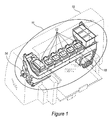
- Figure 1 illustrates an ink delivery system in a printing device, according to an embodiment.
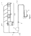
- Figure 2 illustrates a more detailed view of the ink delivery system of Figure 1 , according to an embodiment.
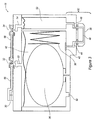
- Figure 3 illustrates a close-up cross-sectional view of a printhead assembly included in the ink delivery system of Figures 1 and 2 , according to an embodi ment.
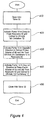
- Figure 4 is a flow chart, illustrating exemplary steps of a "recharge” algorithm, according to an embodiment.
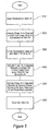
- Figure 5 is a flow chart, illustrating exemplary steps of a "purge" algorithm, according to an embodiment.
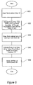
- Figure 6 is a flow chart, illustrating exemplary steps of an "obstruction detection" algorithm, according to an embodiment.
- One exemplary system includes an on-axis printhead assembly having one or more ink reservoirs and a plurality of corresponding nozzles used to eject ink from the respective reservoirs onto a print medium, such as paper.
- the printhead includes a reservoir for each color printable by the printer. Each reservoir is fluidicly connected to a group of corresponding nozzles through a fluid channel.
- a particle filter is disposed between each reservoir and the nozzles to filter unwanted particles as the ink flows from the reservoir to the nozzles.
- the system further includes one or more off-axis ink supply containers for storing quantities of ink. Each reservoir in the printhead assembly is typically fed by a corresponding off-axis ink supply container.
- the system includes a first flow path between each off-axis supply container and the corresponding reservoir of the printhead assembly (upstream of the filter). Further, the system includes a second flow path between each off-axis supply container and the fluid channel downstream of the filter.
- the first flow path facilitates the delivery of ink from the off-axis supply container to the corresponding reservoir and to evacuate air from the printhead assembly upstream of the filter.
- the second flow path is used to evacuate air from the printhead assembly downstream of the filter. Portions of the first and second flow paths may be shared. A bi-directional pump or the like is used to evacuate air through the first and second flow paths.
- the pump and air/ink sensor are used with the second flow path and the first flow path to determine if accretions have formed in the tubes and to remove such accretions from the ink delivery system. Finally, the pump is used with the second flow path to aid in the removal of accretions
- Printing device 10 is used to generate text and/or images on a printing medium, such as paper.
- Printing device 10 includes an ink delivery system 11.
- the ink delivery system includes a printhead assembly 18 and, in this embodiment, a plurality of off-axis ink supply containers 12 (a-f) (collectively referred to as element 12) that each store a supply of a different color of ink.
- the ink supply containers 12 are fluidicly connected to corresponding reservoirs (not shown in Figure 1 ) in the printhead assembly 18 via one or more flow paths (not shown in Figure 1 ), which may consist of plastic tubes.
- Bi-directional pump 14 causes ink to be pumped through the flow paths, both toward the printhead assembly 18, and away from the printhead assembly 18, depending on the activation direction of the pump.
- Various types of bi-directional pumps may be used, including peristaltic pumps.
- bi-directional pump 14 includes an "idle" state. The pump is controlled by a controller and/or electronic control circuit (not shown).
- FIG. 2 illustrates the exemplary ink delivery system 11 in more detail.
- Off-axis ink supply containers 12(a-f) are each connected to corresponding reservoirs (not shown in Figure 2 ) in the printhead assembly 18 through tubes 20(a-f) and 21 (a-f). Tubes 20(a-f) and 21 (a-f) are connected by coupling 22.
- tubes 20(a-f) are static or rigid, and tubes 21 (a-f) are dynamic or flexible to accommodate the moving printhead assembly 18. Further, in some embodiments, tubes 20(a-f) and 21 (a-f) can both be dynamic or both be static.
- each off-axis ink supply container 12 may correspond to and be fluidicly connected to the printhead assembly 18 by a plurality of tubes 12, instead of just one as shown in Figure 2 .
- Bi-directional pump 14 and air/ink sensor 24 are both interposed in the flow path between ink supply containers 12(a-f) and printhead assembly 18 (shown as interposed in tube 21 (a-f) in Figure 2 ).
- the bi-directional pump 14 is configured to selectively move ink and/or air in either direction in the flow path between the ink supply containers 12(a-f) and the printhead assembly 18.
- the air/ink sensor 24 is configured to sense and distinguish between air and/or ink passing therethrough.
- Figure 3 illustrates a close-up cross-sectional view of an exemplary printhead assembly 18.
- Figure 3 shows only the components corresponding to a single reservoir for a single color. It is understood that printhead assembly 18 includes a reservoir (and associated components shown and described in Figure 3 ) for each color printable by the printing system.
- One of the tubes 21 (a-f) (in Figure 2 ) is connected to printhead inlet 30 to provide fluid communication between the off-axis ink supply container 12 and the printhead assembly 18.
- Inlet 30 is fluidicly connected to three-way inlet valve 32.
- One port of inlet valve 32 is connected to fluid channel 56; one port of inlet valve 32 is connected to fluid channel 58; and the third port of inlet valve 32 is connected to fluid channel 52.
- each reservoir 42 includes an accumulator bag 36 and spring 38 along with a bubbler 60 to maintain a slight negative pressure in the reservoir 42, as is known in the art.
- a particle filter 40 separates the reservoir 42 from the lower body portion 62 of the print head assembly 18. As needed, ink may flow through particle filter 40 into inlet channel 44 and ultimately into plenum 46, which resides directly above a slot (not shown). The slot ultimately feeds a thermal printing device (not shown), which ejects ink through nozzles (not shown) disposed in the bottom side 56 of the lower body portion 62 of the printhead assembly 18, according to methods known in the art.
- the plenum 46 is also fluidicly-connected to a two-way recirculation valve 34 via a flow path, which is shown in Figure 3 as comprising a fluid channel 48, a standpipe 50 and a fluid channel 54.
- Recirculation channel 48, snorkel 50 and fluid channel 54 may all be generically and collectively referred to herein as fluid flow paths.
- Recirculation valve 34 is fluidicly-connected to inlet valve 32 via fluid channel 58.
- a bulk supply of each ink is stored in its own ink supply container 12(a-f).
- a relatively small amount (typically, about 2-3 cc) of each ink is stored in the corresponding reservoirs 42 on the printhead assembly 18.
- the printhead assembly causes ink droplets to be ejected from the nozzles (not shown) on the bottom surface 56 of the printhead assembly 18 according to methods known in the art.
- ink droplets are ejected from the nozzles, ink is drawn from reservoir 42 into inlet channel 44 and plenum 46 to replace the ejected ink.
- particle filter 40 is so fine that it prevents air from passing therethrough.
- the reservoirs 42 are “recharged” with ink by drawing ink from the off-axis ink containers 12 into the corresponding reservoirs 42.
- the reservoirs 42 can be “recharged” based on various "triggering events", such as between print jobs or when the ink level in the reservoir dips to a certain pre-defined level.
- triggering events such as between print jobs or when the ink level in the reservoir dips to a certain pre-defined level.
- the steps for one exemplary "recharge” algorithm are described in more detail.
- the inlet valve 32 is opened to provide a flow path into reservoir 42.
- the inlet valve 32 can be opened using various techniques, such as, for example, causing the printhead assembly 18 to move to a predefined location along the shaft so as to mechanically open the inlet valve 32.
- pump 14 is activated so as to draw air and ink from reservoir 42 through inlet valve 32 and to deliver the air and ink to the off-axis ink container 12, where it is pumped through the ink container and vented to atmosphere through vent chambers (not shown).
- the pump 14 draws a pre-determined volume of fluid from each reservoir 42, which is monitored based on the degrees of rotation of pump 14. Normally, the ink levels in each of the reservoirs 42 will be different as a result of using different amounts of the various colors.
- the pre-determined fluid volume is typically chosen so as to ensure that all free air has been removed from all of the reservoirs 42, regardless of the different ink level in the different reservoirs.
- the accumulator bag 36 inflates to replace the volume of air removed.
- the bubble generator 60 begins to operate. Because of the differences in the ink/air volume in each reservoir 42 at the beginning of the "recharge” cycle, each accumulator bag 36 will become fully inflated at a different time.
- the bubble generators 60 act as a kind of pressure relief valve so that the accumulator bags 36 that become fully inflated first, but do not become over inflated. Furthermore, the pressure at which the bubble generators bubble air is significantly lower than the bubble pressure of the nozzles such that, during a "purge” cycle, the nozzles don't ingest air into the standpipe region of the printhead.
- the direction of the pump 14 is reversed at step 430 so as to pump a known volume of air and ink from the off-axis ink containers 12 to the reservoirs 42.
- the actual volume of air/ink pumped into reservoir 42 may be monitored based upon the volume per pump cycle and the number of pump cycles of pump 14, as above.
- the air/ink sensor 24 is used to determine what proportion of the known air/ink volume pumped into the reservoirs 42 is ink and what proportion is air.
- the known volume of air/ink is predetermined so that any reservoirs 42 that were completely depleted of ink before the "recharge” method was employed are now full of ink and that reservoirs 42 that were not completely depleted before the "recharge” method was employed are "overfull” (the reservoirs 42 and accumulator bags 36 are sized to accommodate the "overfull” situation without spilling ink).
- step 440 the direction of pump 14 is again reversed to its original direction.
- Pump 14 now draws a known volume of air and ink from reservoirs 42.
- the ink is returned to the off-axis ink container 12 and the air is vented through the off-axis ink container vent chamber (not shown).
- step 440 all air has been removed from the reservoirs 42.
- an appropriate amount of fluid back pressure has been set in the printhead 18 to ensure optimal printing. Further the ink level in each reservoir has been set.
- inlet valve 32 is closed at step 450. Thereafter, the printing device is ready to print again.
- the purge algorithm can be initiated based upon a variety of different triggering events, such as after a certain amount of ink has been ejected from the printhead nozzles, directly after a "recharge” cycle, after a certain elapsed time, or by the manual initiation of the user (e.g., pushing a button on the print system), for example.
- the "purge” algorithm may also be used to aid in the recovery of plugged nozzles that result from long duration storage.
- the viscous fluid made up of non-volatile solvents that is present in the firing chamber is diluted with ink vehicle containing a sufficient concentration of water so as to enable the formation of a drive bubble that is capable of firing a drop which carries with it the accretion.
- any accretions that may have formed in the nozzles of the printhead assembly 18 will be removed
- recirculation valve 34 is opened.
- a variety of techniques may be used for opening the recirculation valve 34, including, for example, moving the printhead assembly to a predefined location on the shaft so as to mechanically open the recirculation valve 34.
- pump 14 is activated so as to draw air and ink from the lower body 62 of printhead assembly 18 (downstream of filter 40).
- the pump draws a known volume of air and ink from the lower body 62, including fluid flow paths 44, 46, 48, 50 and 54, back into tube 21.
- the known volume is predetermined so as to remove all air and ink from the portion of the printhead assembly downstream of the filter 40..
- the recirculation valve 34 is closed and the inlet valve 32 is opened.
- the pump 14 is activated in the opposite direction so as to pump the air and ink just removed from the lower body 62 back into reservoir 42. In this way, ink removed from the lower body 62 downstream of filter 40 is not wasted.
- step 545 the pump is again reversed and a known volume of air is then removed from reservoir 42 so as to reset the backpressure in reservoir 42.
- inlet valve 32 is closed. At this point, all air has been removed from the lower body 62, downstream of filter 40.
- the above-described "recharge” algorithm includes steps for removing accumulated air from the reservoir 42 of the printhead assembly 18, and the above-described “purge” algorithm removes air from the lower body 62 of printhead assembly 18 downstream of filter 40.
- the "recharge” and “purge” algorithms remove accumulated air from the printhead assembly 18, both upstream and downstream of the filter 40, without ejecting ink from the nozzles.
- the "purge” routine effectively removes accretions from the nozzles of the printhead assembly 18.
- the "recharge" routine in addition to removing accumulated air from the reservoir 42, delivers ink from the off axis ink supply, resets the backpressure in the printhead assembly, and sets the ink level in the printhead reservoirs to ensure optimal printing capability.
- Figure 6 illustrates an "obstruction detection” algorithm that can be selectively implemented in the above-described printing device.
- the "obstruction detection” is configured to determine if an obstruction to the ink flow exists somewhere in the tubes 20 and 21. Obstructions can occur in the tubes 20 and 21 as a result of a kink, for example. Such obstructions may ultimately cause leaks in the printing device as a result of trying to pump ink past the obstructions.
- the "obstruction detection” algorithm begins by opening the recirculation valve 34, as shown at step 610. Then, pump 14 is activated to draw a predetermined amount of ink from the printhead assembly 18 through recirculation valve 34 into tube 21, as shown in step 620.
- the drawn ink - referred to herein as an "ink slug" - is used to determine if there is an obstruction in the ink flow path. Accordingly, the determined amount of ink is normally relatively small. Thereafter, the recirculation valve 34 is closed and inlet valve 32 is opened, as shown at step 630. Pump 14 is activated to draw the ink now in tube 21 back toward ink supply container 12, as shown at step 640. As the ink slug passes through tube 21, it necessarily passes through air/ink sensor 24. The air/ink sensor 24 determines when the ink slug passes, as shown in step 650.
- a controller or other control circuitry determines the elapsed time required for the ink slug to pass by the air/ink sensor 24. If there are no obstructions in the ink flow path (i.e., in the printhead assembly and in the tubes 20 and 21), the ink slug will pass by the air/ink sensor 24 after a known elapsed time. If an obstruction exists somewhere in the ink flow path, then the ink slug will either not pass by the air/ink sensor at all or it will pass by after an elapsed time different than that which is expected or not at all. That is, the ink slug will move through the tubes more slowly than expected. If an obstruction is detected, a variety of actions can be taken, including activating an error message on the printer and/or activating a "purge" routine to attempt to remove an accretion that may have formed in the nozzles, for example.
Landscapes
- Engineering & Computer Science (AREA)
- Quality & Reliability (AREA)
- Ink Jet (AREA)
Claims (9)
- Ein Tintenabgabesystem (11), umfassend:mindestens einen außeraxialen Tintenzufuhrbehälter (12);eine axiale Druckkopfanordnung (18) mit mindestens einem Reservoir (42) und einem entsprechenden Steigrohr (50), das durch einen Partikelfilter (40) getrennt ist;mindestens ein Rohr (20), das den außeraxialen Tintenzufuhrbehälter (12) mit der Druckkopfanordnung (18) verbindet;ein erstes Ventil (32), das konfiguriert ist, einen Strömungsweg zwischen dem Rohr (20) und dem Reservoir (42) selektiv zu öffnen;ein zweites Ventil (34), das konfiguriert ist, einen Strömungsweg zwischen dem Steigrohr (50) und dem Rohr (20) selektiv zu öffnen; undeinen Sensor (24), der in das Rohr (20) eingefügt ist, wobei der Sensor (24) konfiguriert ist, das Vorhandensein von Luft und/oder Tinte zu erfassen.
- Das System (11) nach Anspruch 1, das ferner eine bidirektionale Pumpe (14) umfasst, die in das Rohr (20) eingefügt ist, wobei die Pumpe (14) konfiguriert ist, selektiv Fluid aus der Druckkopfanordnung (18) zu ziehen und Fluid an die Druckkopfanordnung (18) abzugeben.
- Das System (11) nach einem der vorstehenden Ansprüche, wobei die Druckkopfanordnung (18) eine Vielzahl von Reservoirs (42) einschließt, wobei jedes Reservoir (42) mit einem separaten außeraxialen Zufuhrbehälter (12) durch mindestens ein entsprechendes Rohr (20) in Fluidverbindung steht.
- Das System (11) nach einem der vorstehenden Ansprüche, wobei die Druckkopfanordnung (18) ferner einen unteren Körperabschnitt (62) umfasst, der zwischen dem Partikelfilter (40) und dem Steigrohr (50) positioniert ist, wobei der untere Körperabschnitt (62) eine Vielzahl von Düsen aufweist, die konfiguriert sind, Tintentröpfchen als Reaktion auf Steuersignale auszustoßen.
- Das System (11) nach einem der vorstehenden Ansprüche, wobei das Reservoir (42) mit dem außeraxialen Tintenzufuhrbehälter (12) durch ein erstes Rohr (20) in Fluidverbindung steht und das Steigrohr (50) mit dem außeraxialen Tintenzufuhrbehälter (12) durch ein zweites Rohr (20) in Fluidverbindung steht.
- Ein Verfahren zum Steuern von Effekten angesammelter Luft in einer Druckkopfanordnung (18) eines Tintenabgabesystems, wie in einem der Ansprüche 1 bis 5 beansprucht, wobei das Verfahren das Ziehen von Luft aus der Druckkopfanordnung (18) durch das Steigrohr (50) in das Rohr (20) umfasst.
- Das Verfahren nach Anspruch 6, wobei der Schritt des Ziehens das Ziehen von Tinte durch das Steigrohr (50) zusätzlich zu der Luft einschließt.
- Das Verfahren nach einem der Ansprüche 6 oder 7, wobei der Schritt des Ziehens durchgeführt wird, bis im Wesentlichen sämtliche ursprüngliche Luft und Tinte aus der Druckkopfanordnung (18) stromabwärts des Partikelfilters (40) entfernt wurden.
- Das Verfahren nach Anspruch 8, das ferner das Ziehen von Luft aus der Druckkopfanordnung (18) durch das Reservoir (42) in das Rohr (20) umfasst.
Applications Claiming Priority (1)
| Application Number | Priority Date | Filing Date | Title |
|---|---|---|---|
| US11/040,941 US7510274B2 (en) | 2005-01-21 | 2005-01-21 | Ink delivery system and methods for improved printing |
Publications (2)
| Publication Number | Publication Date |
|---|---|
| EP1780025A1 EP1780025A1 (de) | 2007-05-02 |
| EP1780025B1 true EP1780025B1 (de) | 2012-08-08 |
Family
ID=36696327
Family Applications (1)
| Application Number | Title | Priority Date | Filing Date |
|---|---|---|---|
| EP06100670A Expired - Lifetime EP1780025B1 (de) | 2005-01-21 | 2006-01-20 | Tintenzuführsystem und Verfahren zum verbesserten Drucken |
Country Status (3)
| Country | Link |
|---|---|
| US (3) | US7510274B2 (de) |
| EP (1) | EP1780025B1 (de) |
| JP (1) | JP2006199040A (de) |
Families Citing this family (22)
| Publication number | Priority date | Publication date | Assignee | Title |
|---|---|---|---|---|
| US7296881B2 (en) * | 2005-01-21 | 2007-11-20 | Hewlett-Packard Development Company, L.P. | Printhead de-priming |
| US7510274B2 (en) * | 2005-01-21 | 2009-03-31 | Hewlett-Packard Development Company, L.P. | Ink delivery system and methods for improved printing |
| US7575309B2 (en) * | 2005-02-24 | 2009-08-18 | Hewlett-Packard Development Company, L.P. | Fluid supply system |
| US9452605B2 (en) * | 2007-10-25 | 2016-09-27 | Hewlett-Packard Development Company, L.P. | Bubbler |
| US7637602B2 (en) * | 2006-03-03 | 2009-12-29 | Silverbrook Research Pty Ltd | Printer with ink flow shutoff valve |
| US7988265B2 (en) * | 2006-07-27 | 2011-08-02 | Hewlett-Packard Development Company, L.P. | Air detection in inkjet pens |
| JP4940945B2 (ja) * | 2006-12-29 | 2012-05-30 | ブラザー工業株式会社 | 液体吐出装置 |
| JP4841467B2 (ja) * | 2007-03-07 | 2011-12-21 | 株式会社リコー | 画像形成装置 |
| EP2250024A4 (de) * | 2008-03-03 | 2011-05-18 | Silverbrook Res Pty Ltd | Drucker mit ansaugpumpe und stromabwärtiger expansionskammer |
| JP5245993B2 (ja) * | 2009-04-01 | 2013-07-24 | 株式会社リコー | インクジェット記録装置 |
| US20110025738A1 (en) * | 2009-07-31 | 2011-02-03 | Silverbrook Research Pty Ltd | Printer system with printhead carriage connected to ink supply from a single side |
| JP5246107B2 (ja) | 2009-08-31 | 2013-07-24 | ブラザー工業株式会社 | 液体噴射装置 |
| DE112010005233B4 (de) | 2010-02-05 | 2020-07-16 | Vandyne Super Turbo, Inc. | Superturbolader mit hochtourigem Traktionsantrieb und stufenlosen Getriebe |
| US20110279531A1 (en) * | 2010-05-17 | 2011-11-17 | Silverbrook Research Pty Ltd | Maintenance apparatus having cleaner for rotatable wiper |
| US20110279604A1 (en) | 2010-05-17 | 2011-11-17 | Silverbrook Research Pty Ltd | System for flushing printhead and printhead bypass |
| JP5636823B2 (ja) * | 2010-08-28 | 2014-12-10 | 株式会社リコー | 画像形成装置 |
| WO2012030385A1 (en) * | 2010-08-30 | 2012-03-08 | Anajet, Inc. | Inkjet printer ink delivery system |
| JP6260212B2 (ja) * | 2013-11-12 | 2018-01-17 | セイコーエプソン株式会社 | 記録装置 |
| US10065425B2 (en) | 2015-03-06 | 2018-09-04 | Hewlett-Packard Development Company, L.P. | Printing fluid container |
| WO2016200388A1 (en) | 2015-06-11 | 2016-12-15 | Hewlett-Packard Development Company, L.P. | Off-axis printhead assembly attachable to a carriage |
| EP3774355B1 (de) | 2018-08-13 | 2023-12-06 | Hewlett-Packard Development Company, L.P. | Druckflüssigkeitszirkulation |
| US11260669B2 (en) | 2019-10-01 | 2022-03-01 | Hewlett-Packard Development Company, L.P. | Gas purger anomaly condition indication |
Family Cites Families (83)
| Publication number | Priority date | Publication date | Assignee | Title |
|---|---|---|---|---|
| US3739717A (en) * | 1971-07-02 | 1973-06-19 | Riggs & Lombard Inc | Wire printing apparatus having closed inking system |
| GB1527444A (en) * | 1977-03-01 | 1978-10-04 | Itt Creed | Ink drop printhead |
| JPS5675867A (en) * | 1979-11-22 | 1981-06-23 | Seiko Epson Corp | Ink jet recorder |
| US4364059A (en) * | 1979-12-17 | 1982-12-14 | Ricoh Company, Ltd. | Ink jet printing apparatus |
| US4336037A (en) * | 1980-05-19 | 1982-06-22 | Burroughs Corporation | Continuous deaeration system for a fluid pump system |
| US4303929A (en) * | 1980-06-04 | 1981-12-01 | International Business Machines Corporation | Air purging pump for ink jet printers |
| DE3171562D1 (en) * | 1980-06-06 | 1985-09-05 | Epson Corp | Ink supply system for a printer |
| US4329696A (en) * | 1980-07-23 | 1982-05-11 | The Mead Corporation | Ink jet fluid system |
| US4340895A (en) * | 1980-10-14 | 1982-07-20 | Xerox Corporation | Degassing ink supply apparatus for ink jet printer |
| US4333088A (en) * | 1980-11-03 | 1982-06-01 | Exxon Research & Engineering Co. | Disposable peristaltic pump assembly for facsimile printer |
| US4376283A (en) * | 1980-11-03 | 1983-03-08 | Exxon Research And Engineering Co. | Method and apparatus for using a disposable ink jet assembly in a facsimile system and the like |
| US4359744A (en) * | 1980-11-03 | 1982-11-16 | Exxon Research And Engineering Co. | Ink jet printer with peristaltic pump |
| IT1144294B (it) * | 1981-07-10 | 1986-10-29 | Olivetti & Co Spa | Dispositivo di stampa getto selettivo d inchiostro |
| IT1195810B (it) * | 1981-10-05 | 1988-10-27 | Olivetti & Co Spa | Dispositivo di scrittura a getto selettivo di inchiostro relativo in choistro e processo di preparazione dell inchiotro |
| US4403227A (en) * | 1981-10-08 | 1983-09-06 | International Business Machines Corporation | Method and apparatus for minimizing evaporation in an ink recirculation system |
| US4403229A (en) * | 1981-10-30 | 1983-09-06 | International Business Machines Corporation | Maintenance system to prime and to exclude air from ink jet heads |
| US4527175A (en) * | 1981-12-02 | 1985-07-02 | Matsushita Electric Industrial Company, Limited | Ink supply system for nonimpact printers |
| US4413267A (en) * | 1981-12-18 | 1983-11-01 | Centronics Data Computer Corp. | Ink supply system for ink jet printing apparatus |
| US4399446A (en) * | 1982-01-18 | 1983-08-16 | The Mead Corporation | Ink supply system for an ink jet printer |
| US4502055A (en) * | 1982-05-04 | 1985-02-26 | Ricoh Company, Ltd. | Ink jet deaeration apparatus |
| JPS5924676A (ja) * | 1982-07-31 | 1984-02-08 | Sharp Corp | インクジェットプリンタの気泡除去装置 |
| JPS59110638U (ja) * | 1983-01-18 | 1984-07-26 | シャープ株式会社 | インクジエツトプリンタのインク供給装置 |
| US4494124A (en) * | 1983-09-01 | 1985-01-15 | Eastman Kodak Company | Ink jet printer |
| GB8328000D0 (en) * | 1983-10-19 | 1983-11-23 | Domino Printing Sciences Ltd | Hydraulic systems |
| DE3446998A1 (de) * | 1983-12-26 | 1985-07-04 | Canon K.K., Tokio/Tokyo | Tintenstrahl-aufzeichnungsgeraet |
| US4619842A (en) * | 1985-03-28 | 1986-10-28 | At&T Technologies, Inc. | Methods of and apparatus for marking elongated strand material |
| US4727378A (en) * | 1986-07-11 | 1988-02-23 | Tektronix, Inc. | Method and apparatus for purging an ink jet head |
| DE3875757D1 (de) * | 1987-03-13 | 1992-12-17 | Jan Slomianny | Tintensystem fuer tintenstrahlmatrixdrucker. |
| JPH065700B2 (ja) * | 1987-07-22 | 1994-01-19 | 株式会社日立製作所 | 電子回路デバイスの冷却装置 |
| US4835554A (en) * | 1987-09-09 | 1989-05-30 | Spectra, Inc. | Ink jet array |
| US4870431A (en) * | 1987-11-02 | 1989-09-26 | Howtek, Inc. | Ink jet priming system |
| US5291215A (en) * | 1987-11-20 | 1994-03-01 | Canon Kabushiki Kaisha | Ink jet recording apparatus with a thermally stable ink jet recording head |
| US4811035A (en) * | 1988-03-14 | 1989-03-07 | Eastman Kodak Company | Modular two-color fluid system for continuous ink jet printer |
| US4837585A (en) * | 1988-04-25 | 1989-06-06 | Eastman Kodak Company | Continuous ink jet printer having improved system for reducing pressure variations |
| US4929963A (en) * | 1988-09-02 | 1990-05-29 | Hewlett-Packard Company | Ink delivery system for inkjet printer |
| US4940995A (en) * | 1988-11-18 | 1990-07-10 | Spectra, Inc. | Removal of dissolved gas from ink in an ink jet system |
| US4937598A (en) * | 1989-03-06 | 1990-06-26 | Spectra, Inc. | Ink supply system for an ink jet head |
| US5189438A (en) * | 1989-03-06 | 1993-02-23 | Spectra, Inc. | Dual reservoir and valve system for an ink jet head |
| GB9009957D0 (en) * | 1990-05-03 | 1990-06-27 | Domino Printing Sciences Plc | Ink supply system for continuous ink jet printer |
| US5343226A (en) * | 1990-09-28 | 1994-08-30 | Dataproducts Corporation | Ink jet ink supply apparatus |
| US5121130A (en) * | 1990-11-05 | 1992-06-09 | Xerox Corporation | Thermal ink jet printing apparatus |
| JP2725515B2 (ja) * | 1992-03-12 | 1998-03-11 | 株式会社日立製作所 | インクジェット記録装置 |
| US5341162A (en) * | 1992-08-24 | 1994-08-23 | Xerox Corporation | Liquid deagassing apparatus |
| US6000792A (en) * | 1992-09-02 | 1999-12-14 | Canon Kabushiki Kaisha | Ink jet apparatus provided with an improved recovery mechanism |
| US5532720A (en) * | 1993-09-15 | 1996-07-02 | Quad/Tech, Inc. | Solvent recovery system for ink jet printer |
| US5751300A (en) * | 1994-02-04 | 1998-05-12 | Hewlett-Packard Company | Ink delivery system for a printer |
| US5466073A (en) * | 1994-10-21 | 1995-11-14 | Advanced Supplies, Inc. | Printer ribbon cartridge with re-inking reservoir and pump |
| DE4440561C2 (de) * | 1994-11-12 | 1996-10-24 | Pms Gmbh Prod & Recycling | Vorrichtung zum Wiederbefüllen eines Druckkopfs eines Tintenstrahldruckers |
| DE69529884T2 (de) * | 1994-11-30 | 2003-11-13 | Canon K.K., Tokio/Tokyo | Tintenstrahldruckgerät |
| US5956062A (en) * | 1995-01-11 | 1999-09-21 | Canon Kabushiki Kaisha | Liquid jet recording apparatus and recovery method therefor |
| US5870126A (en) * | 1995-01-20 | 1999-02-09 | Hitachi Koki Co., Ltd. | Ink jet printer having bubble purge mechanism |
| FR2729890B1 (fr) * | 1995-01-31 | 1997-04-18 | Neopost Ind | Systeme d'alimentation en encre pour machine d'affranchissement |
| US5831655A (en) * | 1995-03-23 | 1998-11-03 | Seiko Epson Corporation | Ink jet recording apparatus |
| TW365578B (en) * | 1995-04-14 | 1999-08-01 | Canon Kk | Liquid ejecting head, liquid ejecting device and liquid ejecting method |
| US5710579A (en) * | 1995-05-04 | 1998-01-20 | Calcomp Inc. | Sensor system for printers |
| US5936650A (en) * | 1995-05-24 | 1999-08-10 | Hewlett Packard Company | Ink delivery system for ink-jet pens |
| US5818485A (en) * | 1996-11-22 | 1998-10-06 | Xerox Corporation | Thermal ink jet printing system with continuous ink circulation through a printhead |
| US5946015A (en) | 1997-06-02 | 1999-08-31 | Xerox Corporation | Method and apparatus for air removal from ink jet printheads |
| JPH11138773A (ja) * | 1997-11-10 | 1999-05-25 | Fuji Xerox Co Ltd | 画像形成方法および画像形成装置 |
| JP3846083B2 (ja) * | 1998-02-06 | 2006-11-15 | ブラザー工業株式会社 | インクジェット記録装置 |
| US6041709A (en) * | 1998-11-12 | 2000-03-28 | Usadvantage, Inc. | Peristaltic pump for pumping ink or cleaning fluids in a printing machine |
| JP2000289222A (ja) | 1999-04-12 | 2000-10-17 | Canon Inc | 液体吐出記録装置、液体吐出記録装置の液体供給方法、液体吐出記録装置内の液体抜き方法、液体吐出記録装置の液体入れ換え方法 |
| US6428156B1 (en) * | 1999-11-02 | 2002-08-06 | Hewlett-Packard Company | Ink delivery system and method for controlling fluid pressure therein |
| US20020063763A1 (en) * | 2000-11-29 | 2002-05-30 | Mantell David Allen | Apparatus and method for removing air bubbles from an ink jet printhead |
| JP2001232816A (ja) * | 2000-02-25 | 2001-08-28 | Hitachi Koki Co Ltd | インクジェット記録装置及びインク供給方法 |
| US6371607B2 (en) * | 2000-06-29 | 2002-04-16 | Agfa-Gevaert | Ink jet printer and an ink supply system therefore |
| EP1244558B1 (de) * | 2000-10-23 | 2013-02-27 | Hewlett-Packard Industrial Printing Ltd. | Geschlossenes tintenzuführsystem mit druckkopf-tintendruckregelung und zugehöriges verfahren |
| US6478415B2 (en) * | 2001-03-21 | 2002-11-12 | Hewlett-Packard Company | Rejuvenation station and printer cartridge therefore |
| JP2002370374A (ja) * | 2001-06-18 | 2002-12-24 | Canon Inc | インクジェットプリント装置、プリントヘッドおよびインク供給方法 |
| US6742882B2 (en) * | 2001-06-26 | 2004-06-01 | Brother Kogyo Kabushiki Kaisha | Air purge device for ink jet recording apparatus |
| JP2003011380A (ja) | 2001-07-02 | 2003-01-15 | Canon Aptex Inc | インクジェット記録装置 |
| US6491368B1 (en) * | 2001-12-03 | 2002-12-10 | Xerox Corporation | Priming system for multicolor ink jet printers |
| US6955425B2 (en) * | 2002-04-26 | 2005-10-18 | Hewlett-Packard Development Company, L.P. | Re-circulating fluid delivery systems |
| US6752493B2 (en) * | 2002-04-30 | 2004-06-22 | Hewlett-Packard Development Company, L.P. | Fluid delivery techniques with improved reliability |
| US6652080B2 (en) * | 2002-04-30 | 2003-11-25 | Hewlett-Packard Development Company, Lp. | Re-circulating fluid delivery system |
| US7040745B2 (en) * | 2002-10-31 | 2006-05-09 | Hewlett-Packard Development Company, L.P. | Recirculating inkjet printing system |
| JP2004202799A (ja) | 2002-12-25 | 2004-07-22 | Canon Inc | インクジェット記録装置 |
| JP2004237723A (ja) * | 2003-01-17 | 2004-08-26 | Canon Inc | インクジェット記録装置、撮像装置、および当該装置におけるインク供給方法 |
| US6984029B2 (en) * | 2003-07-11 | 2006-01-10 | Hewlett-Packard Development Company, Lp. | Print cartridge temperature control |
| US7431411B2 (en) * | 2003-09-17 | 2008-10-07 | Hewlett-Packard Development Company, L.P. | Refilling a print cartridge reservoir |
| JP4354786B2 (ja) * | 2003-11-28 | 2009-10-28 | 富士フイルム株式会社 | インク濃度検出方法およびインクジェット記録装置 |
| US7331664B2 (en) * | 2004-10-29 | 2008-02-19 | Hewlett-Packard Development Company, L.P. | Ink delivery system and a method for replacing ink |
| US7510274B2 (en) * | 2005-01-21 | 2009-03-31 | Hewlett-Packard Development Company, L.P. | Ink delivery system and methods for improved printing |
-
2005
- 2005-01-21 US US11/040,941 patent/US7510274B2/en not_active Expired - Fee Related
-
2006
- 2006-01-20 EP EP06100670A patent/EP1780025B1/de not_active Expired - Lifetime
- 2006-01-23 JP JP2006013537A patent/JP2006199040A/ja active Pending
-
2008
- 2008-10-30 US US12/261,709 patent/US7997698B2/en not_active Expired - Fee Related
- 2008-10-30 US US12/261,580 patent/US20090058956A1/en not_active Abandoned
Also Published As
| Publication number | Publication date |
|---|---|
| US7510274B2 (en) | 2009-03-31 |
| US20060164473A1 (en) | 2006-07-27 |
| EP1780025A1 (de) | 2007-05-02 |
| US20090058956A1 (en) | 2009-03-05 |
| US20090051742A1 (en) | 2009-02-26 |
| JP2006199040A (ja) | 2006-08-03 |
| US7997698B2 (en) | 2011-08-16 |
Similar Documents
| Publication | Publication Date | Title |
|---|---|---|
| US7997698B2 (en) | Ink delivery system and methods for improved printing | |
| EP0585615B1 (de) | Flüssigkeitsbehälter für Aufzeichnungsgerät | |
| US8550612B2 (en) | Method and system for ink delivery and purged ink recovery in an inkjet printer | |
| JP4219992B2 (ja) | 印刷カートリッジ空気除去装置 | |
| US6883905B2 (en) | Ink jet recording apparatus, control and ink replenishing method executed in the same, ink supply system incorporated in the same, and method of managing ink amount supplied by the system | |
| JP5488052B2 (ja) | 液体噴射装置 | |
| CN101638006B (zh) | 液体供给装置、液体喷出装置和液体喷出装置的控制方法 | |
| US7628475B2 (en) | Printhead evacuation mechanism and method | |
| JP5292037B2 (ja) | インクジェット記録装置 | |
| JP2003326735A (ja) | 印刷カートリッジの流体再循環方法、プライミング方法、保守方法、及び流体放出構造体の熱管理方法 | |
| US8506061B2 (en) | Method and apparatus for purging and supplying ink to an inkjet printing apparatus | |
| US7717540B1 (en) | Clog detection and clearing method for ink delivery system | |
| EP3566875B1 (de) | Flüssigkeitsausstossvorrichtung, flüssigkeitsfüllverfahren und luftblasenabführverfahren | |
| JP2004009450A (ja) | インクジェット記録装置 | |
| JP5983827B2 (ja) | 液体噴射装置 | |
| CN115298034A (zh) | 具有集成过滤器的墨料罐 | |
| HK1101813A (en) | An ink delivery system and methods for improved printing | |
| TW200924991A (en) | Bubbler | |
| WO2009123636A2 (en) | Carriage for carrying a fluid ejector cartridge | |
| JP5776806B2 (ja) | 液体噴射装置 | |
| CN100522626C (zh) | 墨水最初填充次箱的方法及使用该方法的喷墨记录装置 | |
| JP2013126773A (ja) | 液体噴射装置 | |
| US11298951B2 (en) | Liquid ejecting apparatus and method of filling liquid in liquid ejecting apparatus | |
| JP2003089216A (ja) | インクジェット記録装置およびインクジェット記録装置の操作方法 | |
| JP2002321391A (ja) | 液体用流量制御装置、液体容器、液体吐出ヘッド、記録装置、および液体の流量制御方法 |
Legal Events
| Date | Code | Title | Description |
|---|---|---|---|
| PUAI | Public reference made under article 153(3) epc to a published international application that has entered the european phase |
Free format text: ORIGINAL CODE: 0009012 |
|
| AK | Designated contracting states |
Kind code of ref document: A1 Designated state(s): AT BE BG CH CY CZ DE DK EE ES FI FR GB GR HU IE IS IT LI LT LU LV MC NL PL PT RO SE SI SK TR |
|
| AX | Request for extension of the european patent |
Extension state: AL BA HR MK YU |
|
| REG | Reference to a national code |
Ref country code: HK Ref legal event code: DE Ref document number: 1101813 Country of ref document: HK |
|
| 17P | Request for examination filed |
Effective date: 20071102 |
|
| AKX | Designation fees paid |
Designated state(s): AT BE BG CH CY CZ DE DK EE ES FI FR GB GR HU IE IS IT LI LT LU LV MC NL PL PT RO SE SI SK TR |
|
| GRAP | Despatch of communication of intention to grant a patent |
Free format text: ORIGINAL CODE: EPIDOSNIGR1 |
|
| GRAS | Grant fee paid |
Free format text: ORIGINAL CODE: EPIDOSNIGR3 |
|
| GRAA | (expected) grant |
Free format text: ORIGINAL CODE: 0009210 |
|
| AK | Designated contracting states |
Kind code of ref document: B1 Designated state(s): AT BE BG CH CY CZ DE DK EE ES FI FR GB GR HU IE IS IT LI LT LU LV MC NL PL PT RO SE SI SK TR |
|
| REG | Reference to a national code |
Ref country code: GB Ref legal event code: FG4D |
|
| REG | Reference to a national code |
Ref country code: CH Ref legal event code: EP Ref country code: AT Ref legal event code: REF Ref document number: 569532 Country of ref document: AT Kind code of ref document: T Effective date: 20120815 |
|
| REG | Reference to a national code |
Ref country code: IE Ref legal event code: FG4D |
|
| REG | Reference to a national code |
Ref country code: NL Ref legal event code: T3 |
|
| REG | Reference to a national code |
Ref country code: DE Ref legal event code: R096 Ref document number: 602006031225 Country of ref document: DE Effective date: 20121011 |
|
| REG | Reference to a national code |
Ref country code: AT Ref legal event code: MK05 Ref document number: 569532 Country of ref document: AT Kind code of ref document: T Effective date: 20120808 |
|
| REG | Reference to a national code |
Ref country code: LT Ref legal event code: MG4D Effective date: 20120808 |
|
| PG25 | Lapsed in a contracting state [announced via postgrant information from national office to epo] |
Ref country code: AT Free format text: LAPSE BECAUSE OF FAILURE TO SUBMIT A TRANSLATION OF THE DESCRIPTION OR TO PAY THE FEE WITHIN THE PRESCRIBED TIME-LIMIT Effective date: 20120808 Ref country code: CY Free format text: LAPSE BECAUSE OF FAILURE TO SUBMIT A TRANSLATION OF THE DESCRIPTION OR TO PAY THE FEE WITHIN THE PRESCRIBED TIME-LIMIT Effective date: 20120808 Ref country code: LT Free format text: LAPSE BECAUSE OF FAILURE TO SUBMIT A TRANSLATION OF THE DESCRIPTION OR TO PAY THE FEE WITHIN THE PRESCRIBED TIME-LIMIT Effective date: 20120808 Ref country code: IS Free format text: LAPSE BECAUSE OF FAILURE TO SUBMIT A TRANSLATION OF THE DESCRIPTION OR TO PAY THE FEE WITHIN THE PRESCRIBED TIME-LIMIT Effective date: 20121208 Ref country code: FI Free format text: LAPSE BECAUSE OF FAILURE TO SUBMIT A TRANSLATION OF THE DESCRIPTION OR TO PAY THE FEE WITHIN THE PRESCRIBED TIME-LIMIT Effective date: 20120808 |
|
| PG25 | Lapsed in a contracting state [announced via postgrant information from national office to epo] |
Ref country code: BE Free format text: LAPSE BECAUSE OF FAILURE TO SUBMIT A TRANSLATION OF THE DESCRIPTION OR TO PAY THE FEE WITHIN THE PRESCRIBED TIME-LIMIT Effective date: 20120808 Ref country code: SI Free format text: LAPSE BECAUSE OF FAILURE TO SUBMIT A TRANSLATION OF THE DESCRIPTION OR TO PAY THE FEE WITHIN THE PRESCRIBED TIME-LIMIT Effective date: 20120808 Ref country code: PT Free format text: LAPSE BECAUSE OF FAILURE TO SUBMIT A TRANSLATION OF THE DESCRIPTION OR TO PAY THE FEE WITHIN THE PRESCRIBED TIME-LIMIT Effective date: 20121210 Ref country code: LV Free format text: LAPSE BECAUSE OF FAILURE TO SUBMIT A TRANSLATION OF THE DESCRIPTION OR TO PAY THE FEE WITHIN THE PRESCRIBED TIME-LIMIT Effective date: 20120808 Ref country code: GR Free format text: LAPSE BECAUSE OF FAILURE TO SUBMIT A TRANSLATION OF THE DESCRIPTION OR TO PAY THE FEE WITHIN THE PRESCRIBED TIME-LIMIT Effective date: 20121109 Ref country code: PL Free format text: LAPSE BECAUSE OF FAILURE TO SUBMIT A TRANSLATION OF THE DESCRIPTION OR TO PAY THE FEE WITHIN THE PRESCRIBED TIME-LIMIT Effective date: 20120808 Ref country code: SE Free format text: LAPSE BECAUSE OF FAILURE TO SUBMIT A TRANSLATION OF THE DESCRIPTION OR TO PAY THE FEE WITHIN THE PRESCRIBED TIME-LIMIT Effective date: 20120808 |
|
| PG25 | Lapsed in a contracting state [announced via postgrant information from national office to epo] |
Ref country code: RO Free format text: LAPSE BECAUSE OF FAILURE TO SUBMIT A TRANSLATION OF THE DESCRIPTION OR TO PAY THE FEE WITHIN THE PRESCRIBED TIME-LIMIT Effective date: 20120808 Ref country code: DK Free format text: LAPSE BECAUSE OF FAILURE TO SUBMIT A TRANSLATION OF THE DESCRIPTION OR TO PAY THE FEE WITHIN THE PRESCRIBED TIME-LIMIT Effective date: 20120808 Ref country code: EE Free format text: LAPSE BECAUSE OF FAILURE TO SUBMIT A TRANSLATION OF THE DESCRIPTION OR TO PAY THE FEE WITHIN THE PRESCRIBED TIME-LIMIT Effective date: 20120808 Ref country code: CZ Free format text: LAPSE BECAUSE OF FAILURE TO SUBMIT A TRANSLATION OF THE DESCRIPTION OR TO PAY THE FEE WITHIN THE PRESCRIBED TIME-LIMIT Effective date: 20120808 |
|
| PG25 | Lapsed in a contracting state [announced via postgrant information from national office to epo] |
Ref country code: SK Free format text: LAPSE BECAUSE OF FAILURE TO SUBMIT A TRANSLATION OF THE DESCRIPTION OR TO PAY THE FEE WITHIN THE PRESCRIBED TIME-LIMIT Effective date: 20120808 Ref country code: IT Free format text: LAPSE BECAUSE OF FAILURE TO SUBMIT A TRANSLATION OF THE DESCRIPTION OR TO PAY THE FEE WITHIN THE PRESCRIBED TIME-LIMIT Effective date: 20120808 |
|
| PLBE | No opposition filed within time limit |
Free format text: ORIGINAL CODE: 0009261 |
|
| STAA | Information on the status of an ep patent application or granted ep patent |
Free format text: STATUS: NO OPPOSITION FILED WITHIN TIME LIMIT |
|
| 26N | No opposition filed |
Effective date: 20130510 |
|
| PG25 | Lapsed in a contracting state [announced via postgrant information from national office to epo] |
Ref country code: BG Free format text: LAPSE BECAUSE OF FAILURE TO SUBMIT A TRANSLATION OF THE DESCRIPTION OR TO PAY THE FEE WITHIN THE PRESCRIBED TIME-LIMIT Effective date: 20121108 |
|
| PG25 | Lapsed in a contracting state [announced via postgrant information from national office to epo] |
Ref country code: MC Free format text: LAPSE BECAUSE OF NON-PAYMENT OF DUE FEES Effective date: 20130131 |
|
| REG | Reference to a national code |
Ref country code: CH Ref legal event code: PL |
|
| REG | Reference to a national code |
Ref country code: DE Ref legal event code: R097 Ref document number: 602006031225 Country of ref document: DE Effective date: 20130510 |
|
| REG | Reference to a national code |
Ref country code: IE Ref legal event code: MM4A |
|
| PG25 | Lapsed in a contracting state [announced via postgrant information from national office to epo] |
Ref country code: LI Free format text: LAPSE BECAUSE OF NON-PAYMENT OF DUE FEES Effective date: 20130131 Ref country code: CH Free format text: LAPSE BECAUSE OF NON-PAYMENT OF DUE FEES Effective date: 20130131 Ref country code: ES Free format text: LAPSE BECAUSE OF FAILURE TO SUBMIT A TRANSLATION OF THE DESCRIPTION OR TO PAY THE FEE WITHIN THE PRESCRIBED TIME-LIMIT Effective date: 20121119 |
|
| PG25 | Lapsed in a contracting state [announced via postgrant information from national office to epo] |
Ref country code: IE Free format text: LAPSE BECAUSE OF NON-PAYMENT OF DUE FEES Effective date: 20130120 |
|
| PG25 | Lapsed in a contracting state [announced via postgrant information from national office to epo] |
Ref country code: TR Free format text: LAPSE BECAUSE OF FAILURE TO SUBMIT A TRANSLATION OF THE DESCRIPTION OR TO PAY THE FEE WITHIN THE PRESCRIBED TIME-LIMIT Effective date: 20120808 |
|
| PG25 | Lapsed in a contracting state [announced via postgrant information from national office to epo] |
Ref country code: HU Free format text: LAPSE BECAUSE OF FAILURE TO SUBMIT A TRANSLATION OF THE DESCRIPTION OR TO PAY THE FEE WITHIN THE PRESCRIBED TIME-LIMIT; INVALID AB INITIO Effective date: 20060120 Ref country code: LU Free format text: LAPSE BECAUSE OF NON-PAYMENT OF DUE FEES Effective date: 20130120 |
|
| REG | Reference to a national code |
Ref country code: HK Ref legal event code: WD Ref document number: 1101813 Country of ref document: HK |
|
| REG | Reference to a national code |
Ref country code: FR Ref legal event code: PLFP Year of fee payment: 11 |
|
| PGFP | Annual fee paid to national office [announced via postgrant information from national office to epo] |
Ref country code: NL Payment date: 20151217 Year of fee payment: 11 |
|
| REG | Reference to a national code |
Ref country code: FR Ref legal event code: PLFP Year of fee payment: 12 |
|
| REG | Reference to a national code |
Ref country code: NL Ref legal event code: MM Effective date: 20170201 |
|
| REG | Reference to a national code |
Ref country code: FR Ref legal event code: PLFP Year of fee payment: 13 |
|
| PG25 | Lapsed in a contracting state [announced via postgrant information from national office to epo] |
Ref country code: NL Free format text: LAPSE BECAUSE OF NON-PAYMENT OF DUE FEES Effective date: 20170201 |
|
| PGFP | Annual fee paid to national office [announced via postgrant information from national office to epo] |
Ref country code: FR Payment date: 20201217 Year of fee payment: 16 Ref country code: GB Payment date: 20201218 Year of fee payment: 16 |
|
| PGFP | Annual fee paid to national office [announced via postgrant information from national office to epo] |
Ref country code: DE Payment date: 20201217 Year of fee payment: 16 |
|
| REG | Reference to a national code |
Ref country code: DE Ref legal event code: R119 Ref document number: 602006031225 Country of ref document: DE |
|
| GBPC | Gb: european patent ceased through non-payment of renewal fee |
Effective date: 20220120 |
|
| PG25 | Lapsed in a contracting state [announced via postgrant information from national office to epo] |
Ref country code: GB Free format text: LAPSE BECAUSE OF NON-PAYMENT OF DUE FEES Effective date: 20220120 Ref country code: DE Free format text: LAPSE BECAUSE OF NON-PAYMENT OF DUE FEES Effective date: 20220802 |
|
| PG25 | Lapsed in a contracting state [announced via postgrant information from national office to epo] |
Ref country code: FR Free format text: LAPSE BECAUSE OF NON-PAYMENT OF DUE FEES Effective date: 20220131 |