EP1779046B1 - Wärmesteuersystem und -verfahren - Google Patents
Wärmesteuersystem und -verfahren Download PDFInfo
- Publication number
- EP1779046B1 EP1779046B1 EP05748205A EP05748205A EP1779046B1 EP 1779046 B1 EP1779046 B1 EP 1779046B1 EP 05748205 A EP05748205 A EP 05748205A EP 05748205 A EP05748205 A EP 05748205A EP 1779046 B1 EP1779046 B1 EP 1779046B1
- Authority
- EP
- European Patent Office
- Prior art keywords
- temperature
- flow
- refrigerant
- liquid
- pressure
- Prior art date
- Legal status (The legal status is an assumption and is not a legal conclusion. Google has not performed a legal analysis and makes no representation as to the accuracy of the status listed.)
- Active
Links
Images


Classifications
-
- F—MECHANICAL ENGINEERING; LIGHTING; HEATING; WEAPONS; BLASTING
- F25—REFRIGERATION OR COOLING; COMBINED HEATING AND REFRIGERATION SYSTEMS; HEAT PUMP SYSTEMS; MANUFACTURE OR STORAGE OF ICE; LIQUEFACTION SOLIDIFICATION OF GASES
- F25B—REFRIGERATION MACHINES, PLANTS OR SYSTEMS; COMBINED HEATING AND REFRIGERATION SYSTEMS; HEAT PUMP SYSTEMS
- F25B41/00—Fluid-circulation arrangements
-
- F—MECHANICAL ENGINEERING; LIGHTING; HEATING; WEAPONS; BLASTING
- F25—REFRIGERATION OR COOLING; COMBINED HEATING AND REFRIGERATION SYSTEMS; HEAT PUMP SYSTEMS; MANUFACTURE OR STORAGE OF ICE; LIQUEFACTION SOLIDIFICATION OF GASES
- F25B—REFRIGERATION MACHINES, PLANTS OR SYSTEMS; COMBINED HEATING AND REFRIGERATION SYSTEMS; HEAT PUMP SYSTEMS
- F25B15/00—Sorption machines, plants or systems, operating continuously, e.g. absorption type
-
- F—MECHANICAL ENGINEERING; LIGHTING; HEATING; WEAPONS; BLASTING
- F25—REFRIGERATION OR COOLING; COMBINED HEATING AND REFRIGERATION SYSTEMS; HEAT PUMP SYSTEMS; MANUFACTURE OR STORAGE OF ICE; LIQUEFACTION SOLIDIFICATION OF GASES
- F25B—REFRIGERATION MACHINES, PLANTS OR SYSTEMS; COMBINED HEATING AND REFRIGERATION SYSTEMS; HEAT PUMP SYSTEMS
- F25B41/00—Fluid-circulation arrangements
- F25B41/20—Disposition of valves, e.g. of on-off valves or flow control valves
-
- F—MECHANICAL ENGINEERING; LIGHTING; HEATING; WEAPONS; BLASTING
- F25—REFRIGERATION OR COOLING; COMBINED HEATING AND REFRIGERATION SYSTEMS; HEAT PUMP SYSTEMS; MANUFACTURE OR STORAGE OF ICE; LIQUEFACTION SOLIDIFICATION OF GASES
- F25B—REFRIGERATION MACHINES, PLANTS OR SYSTEMS; COMBINED HEATING AND REFRIGERATION SYSTEMS; HEAT PUMP SYSTEMS
- F25B49/00—Arrangement or mounting of control or safety devices
-
- F—MECHANICAL ENGINEERING; LIGHTING; HEATING; WEAPONS; BLASTING
- F25—REFRIGERATION OR COOLING; COMBINED HEATING AND REFRIGERATION SYSTEMS; HEAT PUMP SYSTEMS; MANUFACTURE OR STORAGE OF ICE; LIQUEFACTION SOLIDIFICATION OF GASES
- F25B—REFRIGERATION MACHINES, PLANTS OR SYSTEMS; COMBINED HEATING AND REFRIGERATION SYSTEMS; HEAT PUMP SYSTEMS
- F25B2339/00—Details of evaporators; Details of condensers
- F25B2339/04—Details of condensers
- F25B2339/047—Water-cooled condensers
-
- F—MECHANICAL ENGINEERING; LIGHTING; HEATING; WEAPONS; BLASTING
- F25—REFRIGERATION OR COOLING; COMBINED HEATING AND REFRIGERATION SYSTEMS; HEAT PUMP SYSTEMS; MANUFACTURE OR STORAGE OF ICE; LIQUEFACTION SOLIDIFICATION OF GASES
- F25B—REFRIGERATION MACHINES, PLANTS OR SYSTEMS; COMBINED HEATING AND REFRIGERATION SYSTEMS; HEAT PUMP SYSTEMS
- F25B2400/00—General features or devices for refrigeration machines, plants or systems, combined heating and refrigeration systems or heat-pump systems, i.e. not limited to a particular subgroup of F25B
- F25B2400/04—Refrigeration circuit bypassing means
- F25B2400/0403—Refrigeration circuit bypassing means for the condenser
-
- F—MECHANICAL ENGINEERING; LIGHTING; HEATING; WEAPONS; BLASTING
- F25—REFRIGERATION OR COOLING; COMBINED HEATING AND REFRIGERATION SYSTEMS; HEAT PUMP SYSTEMS; MANUFACTURE OR STORAGE OF ICE; LIQUEFACTION SOLIDIFICATION OF GASES
- F25B—REFRIGERATION MACHINES, PLANTS OR SYSTEMS; COMBINED HEATING AND REFRIGERATION SYSTEMS; HEAT PUMP SYSTEMS
- F25B2400/00—General features or devices for refrigeration machines, plants or systems, combined heating and refrigeration systems or heat-pump systems, i.e. not limited to a particular subgroup of F25B
- F25B2400/04—Refrigeration circuit bypassing means
- F25B2400/0411—Refrigeration circuit bypassing means for the expansion valve or capillary tube
-
- F—MECHANICAL ENGINEERING; LIGHTING; HEATING; WEAPONS; BLASTING
- F25—REFRIGERATION OR COOLING; COMBINED HEATING AND REFRIGERATION SYSTEMS; HEAT PUMP SYSTEMS; MANUFACTURE OR STORAGE OF ICE; LIQUEFACTION SOLIDIFICATION OF GASES
- F25B—REFRIGERATION MACHINES, PLANTS OR SYSTEMS; COMBINED HEATING AND REFRIGERATION SYSTEMS; HEAT PUMP SYSTEMS
- F25B2400/00—General features or devices for refrigeration machines, plants or systems, combined heating and refrigeration systems or heat-pump systems, i.e. not limited to a particular subgroup of F25B
- F25B2400/04—Refrigeration circuit bypassing means
- F25B2400/0415—Refrigeration circuit bypassing means for the receiver
-
- F—MECHANICAL ENGINEERING; LIGHTING; HEATING; WEAPONS; BLASTING
- F25—REFRIGERATION OR COOLING; COMBINED HEATING AND REFRIGERATION SYSTEMS; HEAT PUMP SYSTEMS; MANUFACTURE OR STORAGE OF ICE; LIQUEFACTION SOLIDIFICATION OF GASES
- F25B—REFRIGERATION MACHINES, PLANTS OR SYSTEMS; COMBINED HEATING AND REFRIGERATION SYSTEMS; HEAT PUMP SYSTEMS
- F25B2400/00—General features or devices for refrigeration machines, plants or systems, combined heating and refrigeration systems or heat-pump systems, i.e. not limited to a particular subgroup of F25B
- F25B2400/13—Economisers
-
- F—MECHANICAL ENGINEERING; LIGHTING; HEATING; WEAPONS; BLASTING
- F25—REFRIGERATION OR COOLING; COMBINED HEATING AND REFRIGERATION SYSTEMS; HEAT PUMP SYSTEMS; MANUFACTURE OR STORAGE OF ICE; LIQUEFACTION SOLIDIFICATION OF GASES
- F25B—REFRIGERATION MACHINES, PLANTS OR SYSTEMS; COMBINED HEATING AND REFRIGERATION SYSTEMS; HEAT PUMP SYSTEMS
- F25B2400/00—General features or devices for refrigeration machines, plants or systems, combined heating and refrigeration systems or heat-pump systems, i.e. not limited to a particular subgroup of F25B
- F25B2400/16—Receivers
-
- F—MECHANICAL ENGINEERING; LIGHTING; HEATING; WEAPONS; BLASTING
- F25—REFRIGERATION OR COOLING; COMBINED HEATING AND REFRIGERATION SYSTEMS; HEAT PUMP SYSTEMS; MANUFACTURE OR STORAGE OF ICE; LIQUEFACTION SOLIDIFICATION OF GASES
- F25B—REFRIGERATION MACHINES, PLANTS OR SYSTEMS; COMBINED HEATING AND REFRIGERATION SYSTEMS; HEAT PUMP SYSTEMS
- F25B2600/00—Control issues
- F25B2600/02—Compressor control
- F25B2600/026—Compressor control by controlling unloaders
- F25B2600/0261—Compressor control by controlling unloaders external to the compressor
-
- F—MECHANICAL ENGINEERING; LIGHTING; HEATING; WEAPONS; BLASTING
- F25—REFRIGERATION OR COOLING; COMBINED HEATING AND REFRIGERATION SYSTEMS; HEAT PUMP SYSTEMS; MANUFACTURE OR STORAGE OF ICE; LIQUEFACTION SOLIDIFICATION OF GASES
- F25B—REFRIGERATION MACHINES, PLANTS OR SYSTEMS; COMBINED HEATING AND REFRIGERATION SYSTEMS; HEAT PUMP SYSTEMS
- F25B2600/00—Control issues
- F25B2600/25—Control of valves
- F25B2600/2501—Bypass valves
-
- F—MECHANICAL ENGINEERING; LIGHTING; HEATING; WEAPONS; BLASTING
- F25—REFRIGERATION OR COOLING; COMBINED HEATING AND REFRIGERATION SYSTEMS; HEAT PUMP SYSTEMS; MANUFACTURE OR STORAGE OF ICE; LIQUEFACTION SOLIDIFICATION OF GASES
- F25B—REFRIGERATION MACHINES, PLANTS OR SYSTEMS; COMBINED HEATING AND REFRIGERATION SYSTEMS; HEAT PUMP SYSTEMS
- F25B2700/00—Sensing or detecting of parameters; Sensors therefor
- F25B2700/21—Temperatures
- F25B2700/2115—Temperatures of a compressor or the drive means therefor
- F25B2700/21151—Temperatures of a compressor or the drive means therefor at the suction side of the compressor
-
- F—MECHANICAL ENGINEERING; LIGHTING; HEATING; WEAPONS; BLASTING
- F25—REFRIGERATION OR COOLING; COMBINED HEATING AND REFRIGERATION SYSTEMS; HEAT PUMP SYSTEMS; MANUFACTURE OR STORAGE OF ICE; LIQUEFACTION SOLIDIFICATION OF GASES
- F25B—REFRIGERATION MACHINES, PLANTS OR SYSTEMS; COMBINED HEATING AND REFRIGERATION SYSTEMS; HEAT PUMP SYSTEMS
- F25B2700/00—Sensing or detecting of parameters; Sensors therefor
- F25B2700/21—Temperatures
- F25B2700/2117—Temperatures of an evaporator
-
- F—MECHANICAL ENGINEERING; LIGHTING; HEATING; WEAPONS; BLASTING
- F25—REFRIGERATION OR COOLING; COMBINED HEATING AND REFRIGERATION SYSTEMS; HEAT PUMP SYSTEMS; MANUFACTURE OR STORAGE OF ICE; LIQUEFACTION SOLIDIFICATION OF GASES
- F25B—REFRIGERATION MACHINES, PLANTS OR SYSTEMS; COMBINED HEATING AND REFRIGERATION SYSTEMS; HEAT PUMP SYSTEMS
- F25B30/00—Heat pumps
- F25B30/02—Heat pumps of the compression type
-
- F—MECHANICAL ENGINEERING; LIGHTING; HEATING; WEAPONS; BLASTING
- F25—REFRIGERATION OR COOLING; COMBINED HEATING AND REFRIGERATION SYSTEMS; HEAT PUMP SYSTEMS; MANUFACTURE OR STORAGE OF ICE; LIQUEFACTION SOLIDIFICATION OF GASES
- F25B—REFRIGERATION MACHINES, PLANTS OR SYSTEMS; COMBINED HEATING AND REFRIGERATION SYSTEMS; HEAT PUMP SYSTEMS
- F25B40/00—Subcoolers, desuperheaters or superheaters
-
- F—MECHANICAL ENGINEERING; LIGHTING; HEATING; WEAPONS; BLASTING
- F25—REFRIGERATION OR COOLING; COMBINED HEATING AND REFRIGERATION SYSTEMS; HEAT PUMP SYSTEMS; MANUFACTURE OR STORAGE OF ICE; LIQUEFACTION SOLIDIFICATION OF GASES
- F25B—REFRIGERATION MACHINES, PLANTS OR SYSTEMS; COMBINED HEATING AND REFRIGERATION SYSTEMS; HEAT PUMP SYSTEMS
- F25B49/00—Arrangement or mounting of control or safety devices
- F25B49/02—Arrangement or mounting of control or safety devices for compression type machines, plants or systems
- F25B49/027—Condenser control arrangements
-
- Y—GENERAL TAGGING OF NEW TECHNOLOGICAL DEVELOPMENTS; GENERAL TAGGING OF CROSS-SECTIONAL TECHNOLOGIES SPANNING OVER SEVERAL SECTIONS OF THE IPC; TECHNICAL SUBJECTS COVERED BY FORMER USPC CROSS-REFERENCE ART COLLECTIONS [XRACs] AND DIGESTS
- Y02—TECHNOLOGIES OR APPLICATIONS FOR MITIGATION OR ADAPTATION AGAINST CLIMATE CHANGE
- Y02A—TECHNOLOGIES FOR ADAPTATION TO CLIMATE CHANGE
- Y02A40/00—Adaptation technologies in agriculture, forestry, livestock or agroalimentary production
- Y02A40/90—Adaptation technologies in agriculture, forestry, livestock or agroalimentary production in food processing or handling, e.g. food conservation
- Y02A40/963—Off-grid food refrigeration
Definitions
- thermal transfer fluid which is circulated from the TCU through the equipment and back again in a closed cycle.
- a thermal transfer fluid is selected that is stable in a desired operating range below its boiling temperatures at the minimum operating pressure of said fluid. It also must have suitable viscosity and flow characteristics within its operating range.
- the TCU itself employs a refrigerant, usually now of an ecologically acceptable type, to provide any cooling needed to maintain the selected temperature.
- the TCU may circulate the refrigerant through a conventional liquid/vapor phase cycle. In such cycles, the refrigerant is first compressed to a hot gas at high pressure level, then condensed to a pressurized liquid.
- the gas is transformed to a liquid in a condenser by being passed in close thermal contact with a cooling fluid; it is either liquid cooled by the surrounding fluid or directly by environmental air.
- the liquid refrigerant is then lowered in temperature by expansion through a valve to a selected pressure level. This expansion cools the refrigerant by evaporating some of the liquid, thereby forcing the liquid to equilibrate at the lower saturation pressure.
- the refrigerant is passed into heat exchange relation with the thermal transfer fluid to cool said thermal transfer fluid, in order to maintain the subject equipment at the target temperature level. Then the refrigerant is returned in vapor phase to the pressurization stage.
- a source of heating must usually be supplied to the thermal transfer fluid if it is needed to raise the temperature of the circulated thermal transfer fluid as needed. This is most often an electrical heater placed in heat exchange with the circulated fluid and provided with power as required.
- any change in temperature of the device to be controlled must also affect the conduits connecting the TCU and the controlled device along with the thermal transfer fluid contained in said conduits. This is because the thermal transfer fluid is in intimate thermal contact with the conduit walls.
- the fluid emerging at the conduit end nearest the controlled device arrives at said device at a temperature substantially equal to that of the conduit walls and these walls must be changed in temperature before the controlled device can undergo a like change in temperature.
- Systems and methods in accordance with the invention employ a variable phase refrigerant directly as a cooling or heating source throughout a wide temperature range and with high speed response and high thermal efficiency.
- the refrigerant is maintained as a saturated mix of liquid and vapor during the principal part of its thermal control range and in direct contact with a controlled unit functioning as a variable heat load.
- the temperature of controlled equipment can be adjusted very rapidly by variation of the pressure of the saturated fluid mix. The energy losses in conduits, HEXs and fluid masses are minimized and the delay in temperature response of the cooled device due to the change in temperature of these components is substantially eliminated.
- the invention herein disclosed thus effectively can apply cooling or heating to a controlled device rapidly enough so as to counteract the effects of a change in power applied to the controlled device and thereby keep the controlled device at an invariant temperature.
- a number of novel expedients are utilized to assure that the phases of the refrigerant are stable throughout.
- a balance of input temperature and pressure is maintained at the compressor by employing a desuperheater valve responsive to the compressor input temperature, and a feed-through loop with an electrical heater and heat exchange system is incorporated so as to assure that the input flow at the compressor input is raised to the proper range if necessary.
- This balance also assures that refrigerant returned to the compressor input is free of liquid as well as in a selected pressure range.
- input pressure to the compressor is limited by a close-on-rise valve in the return flow path from the controlled process.
- the system is arranged to enable the control of a unit across a range of temperatures in not only the mixed fluid and hot gas modes, but also in a chilling mode using only thermal expansion of pressurized ambient refrigerant.
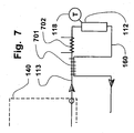
- Fig. 7 is a block diagram of details of a system feature for use in heating the output of the TCU above 120°C employing an auxiliary electric heater and a counter current HEX in a system such as Fig. 1 , and
- a block diagram of a temperature control unit (TCU) 110 is depicted in Fig. 1 for operation principally in the range of approximately -50°C to +140°C, by way of example only. Other temperature ranges may be utilized, depending upon the refrigerant and to some extent the load, but the example given assumes the use of refrigerant R507 as an example.
- TCU 110 can be a compact unit and is characterized by low cost as well as moderate size, enhanced economy and rapid response. Temperature levels are to be held stable at different target levels irrespective of the lengths of the lines coupling associated devices.
- the TCU 110 in this example is intended for the purpose of controlling the temperature of a tool 112, such as a cluster tool for semiconductor fabrication. Such tools have internal passageways for passage of a thermal control fluid.
- the TCU is intended to establish different target temperatures of the tool for operating cycles during different fabrication steps.
- the hot gas flow from the compressor 158 branches into two flow paths, one of which enters a compressor control system 120 including a conventional condenser 156 including a heat exchanger (HEX) 104 that is liquid cooled by a facility water source 154.
- HEX heat exchanger
- An air cooled condenser could equally well be employed, and liquid cooling is chosen as an example only.
- Water is supplied to HEX 104 in condenser 156 through either a controlled water valve 106 responsive to the output pressure of compressor 158 or a controllable bypass valve 105 that is responsive to the controller 114.
- Bypass valve 105 is activated whenever a maximum cooling effort is needed. Opening valve 105 assures that the condenser 156 is supplied with the coldest water possible.
- the fluid in the liquid line 132 from the subcooler 130 is paralleled by the separate hot gas flow in hot gas line 159, and both lead to a mixing circuit 140.
- the hot gas flow in line 159 traverses a proportional valve 144, which valve is controlled by controller 114 signals which assure selected reduction in pressure in the hot gas flow provided into the mixing circuit 140.
- the valve 144 varies the mass flow, which ultimately varies the pressure.
- a separate input provided to the mixing circuit 140 from the vapor/liquid line 132 is controlled via a thermal expansion valve (TXV) 157. This operates as a normal refrigeration valve of the thermostatic expansion type.
- TXV thermal expansion valve
- the TXV 157 is externally equalized by the pressure communicated via the conduit 149 with the return line from the tool 112.
- the TXV 157 output flows through a delta P valve 155, which comprises a spring-loaded check valve establishing a fluid pressure drop (delta p) between the output of the TXV 157 and the mixing Tee 165.
- the total pressure across the delta P valve 155 is greater than the pressure drop across a fully open proportional valve 144 in the hot gas line when all the output of the compressor 159 is diverted to flow only across proportional valve 144.
- the system also includes a "Close on Rise” (COR) valve 150 in the return line from the tool 112 to act as a safeguard against excessive pressure buildup in the pressure input at the compressor 158.
- COR Click on Rise
- This is a commercially available refrigeration component and is traditionally used for this purpose. In the subject invention it serves the same purpose but also allows the TCU to act as a heat pump as will be explained below.
- the two streams of refrigerant are combined at the mixing Tee 165. After such mixing has occurred the output flow travels through supply line 113 to cool or heat the tool 112. After leaving tool 112 the mix of vapor and liquid returns to the TCU through return line 160.
- the capacity for thermal energy interchange is substantially higher than in a pure liquid or pure gaseous phase, because the dynamics of evaporation and liquefaction enhance the ability to transfer heat to a surface, as opposed to the strictly heat conductive effects existing in both the pure liquid and pure gas phases.
- a temperature change with a fluid in the pure gas phase and a temperature change in the purely liquid phase are both dependent solely upon thermal energy conduction.
- Transport of vapor into and out of the liquid droplets can be viewed as strictly dependent on pressure or temperature, with the lower the pressure the lower the temperature of evaporation. From an equilibrium temperature, however, heat is supplied to a cooling source until all of the vapor is liquefied, or heat is taken up in evaporation, at a substantially constant temperature, until the entire mass is evaporated or condensed.
- a liquid/vapor mix can be used as a constant temperature sink or source and, contrary-wise, that by varying the pressure, the temperature of a unit in thermal exchange relation with the liquid/vapor mix can be varied. It is significant that this variation can be extremely rapid because of the fact that pressure changes are transported through a fluid at the speed of sound; hundreds of meters per second..
- the crucial mixing zone comprises the elements within mixing system 140 which includes the hot gas output from the proportional valve 144 and the output of liquid and vapor from TXV 157, both of which branch from the compressor 158 output line 102.
- the liquefied output from the cooled condenser 156 to the TXV 157 will be at a substantially like pressure.
- the TXV 157 After expansion at the TXV 157, as commanded by controller 114, the TXV 157 provides a misted liquid flow. This can be viewed classically as a dispersion of droplets within a surrounding atmosphere of liquid vapor.
- Mixing circuit 140 further includes the delta p valve 155, which introduces a pressure drop substantially no greater than the inherent drop in the proportional valve 144, when said proportional valve 144 is wide open. Furthermore, the mixing head 165 and delta p valve 155 prevent back-flow of the mix into the liquid/vapor line 132 when valve 144 is wide open.
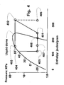
- the evaporation point of the refrigerant is about 45°C at 27*10 5 Pa (400 psi).
- the pressure is dropped to a selected level, without changing the enthalpy, as the refrigerant is expanded, as shown from points 404-405.
- the expanded refrigerant, released as liquid/vapor mixture moves through the liquid dome transition in the line from 405-401, and is directed through the heat exchange area.
- the gas is recompressed following point 401 and the cycle is repeated.
- the present invention modifies the basic refrigeration cycle to accomplish the objectives of a modem TCU with more flexibility.
- the Mollier diagram (a display of enthalpy versus temperature in the vicinity of the liquid dome) of refrigerant (type R 507) shown in Fig. 4 shows the operation of the refrigerant in providing a flow of liquid and vapor at -20°C, which temperature is chosen as an example.
- the invention provides for a variation in the heating or cooling capabilities of the fluid under rapid control of the unit.
- the refrigeration cycle is shown from point 401 which is taken at the compressor input 163 ( Fig. 1 ).
- the gas is compressed to point 402, which point is about 30 KPa (ca. 400psig) at a temperature of about 120°C.
- Gas that enters the condenser 156 is cooled and liquefied to point 403 at a temperature of around 60°C.
- This liquid is passed through subcooler 130.
- the liquid is cooled by exchanging heat with the refrigerant returning from the tool 112 in line 161.
- Liquid refrigerant thus cooled in subcooler 130 is then expanded through TXV 157 to point 404.
- the refrigerant is at a temperature of around -20°C and consists of about 50% gas and 50% liquid in the current example.
- This is mixed with hot gas expanded through proportional valve 144 and depicted on Fig. 4 by the dotted line path from point 402 to point 406 which, in the present example would be at a temperature of about 85°C.
- Fig. 5 shows the thermodynamic performance of the TCU fitted with a subsystem such as in Fig. 7 .
- Refrigerant gas enters the compressor at point 507. It is then compressed to about 30 KPa at point 501 where the gas enters HEX 701.
- the input gas is heated to point 502 in absorbing heat from the outgoing gas as it is cooled from point 508 to point 505.
- the electrical heater 702 then heats the input gas from point 502 to point 503 which is the temperature at which the gas enters tool 112, assuming there is negligible loss in gas temperature as it passes from heater 702 to tool 112 through line 113.
- the gas is cooled in the process of heating tool 112 from point 504 to point 508.
- the gas enters HEX 701 and cools to point 505 in heating the input gas on the other side of HEX 701.
- the gas then passes through COR valve 150 and drops to a pressure at point 506 suitable for the compressor 158 input.
- the gas would be ready to restart its cycle and be compressed again except it is too hot for successful operation of the compressor.
- the hot gas mixes with the output of desuperheater valve 134 which is opened in response to the sensor 126 at the compressor 158 input. This action adds a fraction of condensed refrigerant at the return side of the subcooler 130.
- the combination of the condensed liquid fraction from the condenser 156 which is at point 511 in Fig.
- COR valve 150 can come into play at lower temperatures under particular circumstances. If the TCU is called into operation at a temperature significantly over 10°C the pressure at which liquid and gas equilibrate in the refrigerant will be too high for successful compression in conventional compressors. Referring to Figs. 1 and 5 , COR valve 150 protects the compressor 158 when, as is shown in Fig. 6 , the TCU is being called on to cool a load at 40°C (in a manner similar to that shown in Fig. 4 wherein the tool was cooled with refrigerant at -20°C). Fig. 6 shows the gas being compressed from point 601 to point 602.
- this gas then is condensed at the same pressure to point 603 and expanded through TXV valve 157 to point 604. The remainder of the compressed gas is allowed to pass through the proportional valve 144 to point 605. The two streams are then combined in mixing circuit 140 to exit at an intermediate pressure and enthalpy point 607. The liquid in this mixture, which is supplied to the tool 112, is then evaporated in cooling tool 112 to point 608. The gas at this point is then processed automatically in COR valve 150 to expand to a lower pressure suitable to enter compressor 158 at point 601. The cycle then repeats.
- the TCU can perform as a heat pump in supplying heat at a desired point. This is shown in Figure 8 which should also be considered along with Fig. 1 .
- the operation shown herein is for supplying close to maximum heating at a temperature around 40°C.
- Controller 114 mixes an amount of condensed but high pressure liquid at point 803 that has been expanded through TXV 157 to point 809 with the gas at point 805 to provide a mixture at point 810.
- the combination is then passed through tool 112 giving up heat to tool 112 in condensing liquid to point 804.
- a pressure switch 168 shown in Fig. 1 senses this and activates heater 117 whenever the pressure sensed by switch 168 is below the threshold value. This action heats the liquid/vapor mix at point 811 and heats it to point 808 outside the liquid where it enters COR valve 150 and expands to point 801 where it then is all gas and ready to be recompressed.
- a separate control is effected at the condenser 156.
- the compressor 158 output is sensed by the pressure sensor 118, and a signal is returned to the controller 114, the consequent variation of the facility water source 154 assures that the condenser 156 is cooled sufficiently by the HEX 104 to maintain the refrigerant flow in the liquid line 132 substantially constant.
- This system therefore provides a highly efficient heat exchange system in which the refrigerant is used directly under variable load conditions but maintained in a controlled, misted liquid/vapor phase when in contact with the tool 112.
- This control in a principal mode is maintained by the controller 114 adjusting the proportions of the hot gas and the expanded liquid refrigerant at a selected pressure as determined by the heating or cooling needs of the tool 112 at a specific target temperature. Subsequent heat exchange in the tool itself may well occur, and the system and method stabilize or condition the refrigerant throughout the cycle.
- the proportional valve 144 is opened to create the flow rate and temperature at the tool needed for maintenance of the target temperature, which with R507 refrigerant is thereby approximately 150° or more.
- the TXV 157 is controlled to provide a cooling output to the tool 112 down to about -40°C.
Landscapes
- Engineering & Computer Science (AREA)
- Physics & Mathematics (AREA)
- Mechanical Engineering (AREA)
- Thermal Sciences (AREA)
- General Engineering & Computer Science (AREA)
- Control Of Temperature (AREA)
- Devices That Are Associated With Refrigeration Equipment (AREA)
- Compression-Type Refrigeration Machines With Reversible Cycles (AREA)
- Separation By Low-Temperature Treatments (AREA)
- Heating, Cooling, Or Curing Plastics Or The Like In General (AREA)
- Steam Or Hot-Water Central Heating Systems (AREA)
- Adhesives Or Adhesive Processes (AREA)
- Surgical Instruments (AREA)
- Treatment Of Sludge (AREA)
Claims (13)
- Verfahren zum Regeln der Temperatur einer thermischen Last (112) zur genauen Aufrechterhaltung einer Solltemperatur, mit den folgenden Schritten:Komprimieren eines umlaufenden Kältemittels zur Bereitstellung eines beaufschlagten Heißgasstroms;Abtrennen des beaufschlagten Heißgasstroms in einen ersten beaufschlagten Heißgasstrom, dessen Durchflussmenge und Druck mit einem Ventil (144) variabel regelbar sind;Kondensieren eines verbleibenden zweiten Stroms, der nach dem Abtrennen von dem vollen Strom abgezweigt wird; undExpandieren des zweiten Stroms zu einem zweiten Strom aus kondensierter Flüssigkeit/Dampfnebel des Kältemittels mittels eines Wärmedehnungsventils (157), wobeiin einem Hauptbetriebsmodus das Wärmedehnungsventil (157) einen gewählten Teil der Flüssigkeit / des Dampfnebels des Kältemittels für die Vereinigung mit dem Heißgasstrom von dem Ventil (144) liefert, wenn das Ventil (144) nicht vollständig geschlossen ist,im Fall einer extremen Erwärmung der zweite Strom von dem Wärmedehnungsventil (157) durch volles Öffnen des Ventils (144) vollständig abgesperrt werden kann undin einem Kühlmodus nur die Wärmedehnung des beaufschlagten Kältemittels genutzt wird;Vereinigen des ersten Stroms und des zweiten Stroms an einem Mischkopf (165) in einem Mischkreislauf (140);Durchleiten des gemischten Stroms durch die thermische Last (112), um deren Temperatur zu regeln;Messen der Temperatur des geregelten Prozesses oder der geregelten Einrichtung und Senden der Temperatur an einen Regler (114);Ändern der Temperatur des geregelten Systems mit dem Regler (114) durch Druckänderung, die eine Abkühlung oder Erwärmung bewirkt, als Folge des Änderns des Massenstroms des ersten Stroms mit dem Ventil (144) undWiederherstellen des Stroms von der thermischen Last (112) zu einem Gas, das für eine erneute Beaufschlagung geeignet ist.
- Verfahren nach Anspruch 1, dadurch gekennzeichnet, dass der gesättigte Dampfnebel in dem Hauptmodusbereich aufrechterhalten wird, in dem eine Änderung des Drucks eine Wärmeenergieübertragung aufgrund der latenten Verdampfungs- oder Kondensationswärme umfasst.
- Verfahren nach Anspruch 2, das den Schritt der Bereitstellung eines Bereichs hoher Temperatur umfasst, in dem der Strom ausschließlich Hochtemperaturgas ist.
- Verfahren nach Anspruch 3, das den Schritt umfasst, das Hochtemperaturgas weiter zu erwärmen, bevor es zu der thermischen Last (112) geleitet wird.
- Verfahren nach Anspruch 1, das den Schritt umfasst, die Temperatur so einzustellen, dass die Temperatur der thermischen Last (112) korrigiert wird, die von demTemperatursensor (118) in Reaktion auf die Temperatur der thermischen Last (112) gemessen wird, und diese an den Regler (114) zu senden.
- Verfahren nach Anspruch 1, das den Schritt umfasst, die Temperatur der thermischen Last (112) durch Ändern des Drucks des gesättigten Fluidgemisches sehr schnell einzustellen.
- Verfahren nach Anspruch 1, das die Verwendung nur der Wärmedehnung des beaufschlagten Umgebungskältemittels umfasst.
- Verfahren nach Anspruch 1, das das Aufrechterhalten des Kältemittels als gesättigtes Gemisch aus Flüssigkeit und Dampf in dem Hauptteil seines Temperaturregelbereiches und das Halten des Kältemittels in direktem Kontakt mit einer als variable thermische Last (112) fungierenden geregelten Einheit umfasst.
- Verfahren nach Anspruch 1, das das Festlegen der Temperatur des gesättigten Fluidgemisches durch Halten von Flüssigkeitströpfchen und Dampfnebel im Gleichgewicht auf einem gewählten Druck umfasst.
- Verfahren nach Anspruch 1, dadurch gekennzeichnet, dass ab der Gleichgewichtstemperatur Wärme einer Kühllast (112) zugeführt wird, bis der gesamte Dampf verflüssigt ist, oder Wärme bei der Verdampfung aufgenommen wird, bis die gesamte Masse verdampft oder kondensiert ist.
- Verfahren nach Anspruch 1, das das Vereinigen des zweiten Stroms aus kondensierter Flüssigkeit/Dampfnebel mit dem ersten Regler-geregelten beaufschlagten Heißgasstrom, der ebenfalls an dem Mischkopf (165) ankommt, umfasst, was zu einer Verringerung einer geregelten Größe der Tröpfchen führt, die durch die Notwendigkeit bedingt ist, die Temperatur in dem gesamten Mischstrom aus Flüssigkeit und Dampf von dem Wärmedehnungsventil (157) mit dem Heißgas von dem Proportionalventil (144) ins Gleichgewicht zu bringen.
- Verfahren nach Anspruch 1, das den Schritt umfasst, eine gegebene Temperatur (T), die an der thermischen Last (112) von dem Sensor (118) ermittelt wird, aufrechtzuerhalten, wobei der Druck in dem Mischstrom aus Dampf/Flüssigkeit in einer Speiseleitung (113) durch Verstellen der Öffnung des Ventils (144) so eingestellt wird, dass die Durchflussmenge geändert wird, wodurch die Temperatur in der Leitung (113) entsprechend geändert wird, wenn Dampf und Flüssigkeit bei der eingestellten Sättigungstemperatur ins Gleichgewicht kommen, um die Temperatur der Last (112) konstant zu halten.
- Verfahren nach Anspruch 1, das den weiteren Schritt umfasst, einen Druckabfall in dem zweiten, expandierten Strom einzuleiten, um Strom-Nichtlinearitäten zu kompensieren, die dem Wärmedehnungsventil (157) innewohnen.
Priority Applications (3)
| Application Number | Priority Date | Filing Date | Title |
|---|---|---|---|
| EP09161173A EP2096379B1 (de) | 2004-06-02 | 2005-05-12 | Verfahren zur Regelung der Temperatur einer Wärmebelastung |
| EP09161171A EP2098808B1 (de) | 2004-06-02 | 2005-05-12 | Wärmeregelungsgerät |
| EP09161174A EP2096380B1 (de) | 2004-06-02 | 2005-05-12 | System zur Regelung der Temperatur in einer Verarbeitungseinheit |
Applications Claiming Priority (3)
| Application Number | Priority Date | Filing Date | Title |
|---|---|---|---|
| US57670504P | 2004-06-02 | 2004-06-02 | |
| US11/057,383 US7178353B2 (en) | 2004-02-19 | 2005-02-15 | Thermal control system and method |
| PCT/US2005/016740 WO2005121657A2 (en) | 2004-06-02 | 2005-05-12 | Thermal control system and method |
Related Child Applications (3)
| Application Number | Title | Priority Date | Filing Date |
|---|---|---|---|
| EP09161174A Division EP2096380B1 (de) | 2004-06-02 | 2005-05-12 | System zur Regelung der Temperatur in einer Verarbeitungseinheit |
| EP09161171A Division EP2098808B1 (de) | 2004-06-02 | 2005-05-12 | Wärmeregelungsgerät |
| EP09161173A Division EP2096379B1 (de) | 2004-06-02 | 2005-05-12 | Verfahren zur Regelung der Temperatur einer Wärmebelastung |
Publications (3)
| Publication Number | Publication Date |
|---|---|
| EP1779046A2 EP1779046A2 (de) | 2007-05-02 |
| EP1779046A4 EP1779046A4 (de) | 2008-02-13 |
| EP1779046B1 true EP1779046B1 (de) | 2009-10-28 |
Family
ID=35503754
Family Applications (4)
| Application Number | Title | Priority Date | Filing Date |
|---|---|---|---|
| EP09161174A Active EP2096380B1 (de) | 2004-06-02 | 2005-05-12 | System zur Regelung der Temperatur in einer Verarbeitungseinheit |
| EP09161173A Active EP2096379B1 (de) | 2004-06-02 | 2005-05-12 | Verfahren zur Regelung der Temperatur einer Wärmebelastung |
| EP09161171A Active EP2098808B1 (de) | 2004-06-02 | 2005-05-12 | Wärmeregelungsgerät |
| EP05748205A Active EP1779046B1 (de) | 2004-06-02 | 2005-05-12 | Wärmesteuersystem und -verfahren |
Family Applications Before (3)
| Application Number | Title | Priority Date | Filing Date |
|---|---|---|---|
| EP09161174A Active EP2096380B1 (de) | 2004-06-02 | 2005-05-12 | System zur Regelung der Temperatur in einer Verarbeitungseinheit |
| EP09161173A Active EP2096379B1 (de) | 2004-06-02 | 2005-05-12 | Verfahren zur Regelung der Temperatur einer Wärmebelastung |
| EP09161171A Active EP2098808B1 (de) | 2004-06-02 | 2005-05-12 | Wärmeregelungsgerät |
Country Status (7)
| Country | Link |
|---|---|
| US (3) | US7178353B2 (de) |
| EP (4) | EP2096380B1 (de) |
| JP (2) | JP5197004B2 (de) |
| KR (1) | KR100970065B1 (de) |
| AT (3) | ATE447150T1 (de) |
| DE (3) | DE602005027759D1 (de) |
| WO (1) | WO2005121657A2 (de) |
Families Citing this family (85)
| Publication number | Priority date | Publication date | Assignee | Title |
|---|---|---|---|---|
| US8034180B2 (en) * | 2005-10-11 | 2011-10-11 | Applied Materials, Inc. | Method of cooling a wafer support at a uniform temperature in a capacitively coupled plasma reactor |
| US7988872B2 (en) * | 2005-10-11 | 2011-08-02 | Applied Materials, Inc. | Method of operating a capacitively coupled plasma reactor with dual temperature control loops |
| US8157951B2 (en) * | 2005-10-11 | 2012-04-17 | Applied Materials, Inc. | Capacitively coupled plasma reactor having very agile wafer temperature control |
| US8092638B2 (en) * | 2005-10-11 | 2012-01-10 | Applied Materials Inc. | Capacitively coupled plasma reactor having a cooled/heated wafer support with uniform temperature distribution |
| US8608900B2 (en) * | 2005-10-20 | 2013-12-17 | B/E Aerospace, Inc. | Plasma reactor with feed forward thermal control system using a thermal model for accommodating RF power changes or wafer temperature changes |
| US20070164426A1 (en) * | 2006-01-18 | 2007-07-19 | International Business Machines Corporation | Apparatus and method for integrated circuit cooling during testing and image based analysis |
| DE102006016950B4 (de) * | 2006-04-11 | 2010-09-23 | LacTec Gesellschaft für moderne Lackiertechnik mbH | Lackiereinrichtung und Verfahren zum Ausbringen von Lack |
| US20070240870A1 (en) * | 2006-04-18 | 2007-10-18 | Daytona Control Co., Ltd. | Temperature control apparatus |
| SG136816A1 (en) * | 2006-04-18 | 2007-11-29 | Daytona Control Co Ltd | Temperature control apparatus |
| JP4996184B2 (ja) * | 2006-09-19 | 2012-08-08 | 東京エレクトロン株式会社 | ウエハの温度制御装置及びウエハの温度制御方法 |
| WO2008095009A2 (en) * | 2007-01-30 | 2008-08-07 | Bradley University | A heat transfer apparatus and method |
| JP5020664B2 (ja) * | 2007-03-09 | 2012-09-05 | 関東精機株式会社 | 工作機械の温度制御装置 |
| US20090025405A1 (en) * | 2007-07-27 | 2009-01-29 | Johnson Controls Technology Company | Economized Vapor Compression Circuit |
| KR101460222B1 (ko) * | 2007-10-09 | 2014-11-10 | 비/이 에어로스페이스 인코포레이티드 | 열적 제어 시스템 및 방법 |
| US8240160B2 (en) * | 2008-03-25 | 2012-08-14 | Be Aerospace, Inc. | Thermal control system and method |
| US8240140B2 (en) | 2008-04-09 | 2012-08-14 | Sustainx, Inc. | High-efficiency energy-conversion based on fluid expansion and compression |
| US8474255B2 (en) | 2008-04-09 | 2013-07-02 | Sustainx, Inc. | Forming liquid sprays in compressed-gas energy storage systems for effective heat exchange |
| US20100307156A1 (en) | 2009-06-04 | 2010-12-09 | Bollinger Benjamin R | Systems and Methods for Improving Drivetrain Efficiency for Compressed Gas Energy Storage and Recovery Systems |
| US7958731B2 (en) | 2009-01-20 | 2011-06-14 | Sustainx, Inc. | Systems and methods for combined thermal and compressed gas energy conversion systems |
| US8479505B2 (en) | 2008-04-09 | 2013-07-09 | Sustainx, Inc. | Systems and methods for reducing dead volume in compressed-gas energy storage systems |
| US8448433B2 (en) | 2008-04-09 | 2013-05-28 | Sustainx, Inc. | Systems and methods for energy storage and recovery using gas expansion and compression |
| US8037678B2 (en) | 2009-09-11 | 2011-10-18 | Sustainx, Inc. | Energy storage and generation systems and methods using coupled cylinder assemblies |
| US8677744B2 (en) | 2008-04-09 | 2014-03-25 | SustaioX, Inc. | Fluid circulation in energy storage and recovery systems |
| US20110266810A1 (en) | 2009-11-03 | 2011-11-03 | Mcbride Troy O | Systems and methods for compressed-gas energy storage using coupled cylinder assemblies |
| US8250863B2 (en) | 2008-04-09 | 2012-08-28 | Sustainx, Inc. | Heat exchange with compressed gas in energy-storage systems |
| US7832207B2 (en) | 2008-04-09 | 2010-11-16 | Sustainx, Inc. | Systems and methods for energy storage and recovery using compressed gas |
| US8225606B2 (en) | 2008-04-09 | 2012-07-24 | Sustainx, Inc. | Systems and methods for energy storage and recovery using rapid isothermal gas expansion and compression |
| US8359856B2 (en) | 2008-04-09 | 2013-01-29 | Sustainx Inc. | Systems and methods for efficient pumping of high-pressure fluids for energy storage and recovery |
| WO2009152141A2 (en) | 2008-06-09 | 2009-12-17 | Sustainx, Inc. | System and method for rapid isothermal gas expansion and compression for energy storage |
| US8532832B2 (en) * | 2008-09-23 | 2013-09-10 | Be Aerospace, Inc. | Method and apparatus for thermal exchange with two-phase media |
| US9155134B2 (en) | 2008-10-17 | 2015-10-06 | Applied Materials, Inc. | Methods and apparatus for rapidly responsive heat control in plasma processing devices |
| US7963110B2 (en) | 2009-03-12 | 2011-06-21 | Sustainx, Inc. | Systems and methods for improving drivetrain efficiency for compressed gas energy storage |
| US8453468B1 (en) * | 2009-03-18 | 2013-06-04 | Be Aerospace, Inc. | System and method for thermal control of different heat loads from a single source of saturated fluids |
| WO2010111560A1 (en) * | 2009-03-25 | 2010-09-30 | Pax Streamline, Inc. | Supersonic cooling system |
| US8820114B2 (en) | 2009-03-25 | 2014-09-02 | Pax Scientific, Inc. | Cooling of heat intensive systems |
| US20110048062A1 (en) * | 2009-03-25 | 2011-03-03 | Thomas Gielda | Portable Cooling Unit |
| US8505322B2 (en) * | 2009-03-25 | 2013-08-13 | Pax Scientific, Inc. | Battery cooling |
| US20110030390A1 (en) * | 2009-04-02 | 2011-02-10 | Serguei Charamko | Vortex Tube |
| US8104274B2 (en) | 2009-06-04 | 2012-01-31 | Sustainx, Inc. | Increased power in compressed-gas energy storage and recovery |
| US20110051549A1 (en) * | 2009-07-25 | 2011-03-03 | Kristian Debus | Nucleation Ring for a Central Insert |
| US8365540B2 (en) * | 2009-09-04 | 2013-02-05 | Pax Scientific, Inc. | System and method for heat transfer |
| US20110058637A1 (en) * | 2009-09-09 | 2011-03-10 | International Business Machines Corporation | Pressure control unit and method facilitating single-phase heat transfer in a cooling system |
| US20110056675A1 (en) | 2009-09-09 | 2011-03-10 | International Business Machines Corporation | Apparatus and method for adjusting coolant flow resistance through liquid-cooled electronics rack(s) |
| US8583290B2 (en) * | 2009-09-09 | 2013-11-12 | International Business Machines Corporation | Cooling system and method minimizing power consumption in cooling liquid-cooled electronics racks |
| US8322154B2 (en) * | 2009-09-09 | 2012-12-04 | International Business Machines Corporation | Control of system coolant to facilitate two-phase heat transfer in a multi-evaporator cooling system |
| DK2491317T3 (en) | 2009-10-23 | 2018-08-06 | Carrier Corp | OPERATING COOLANT Vapor Compression System |
| US9453669B2 (en) * | 2009-12-08 | 2016-09-27 | Thermo King Corporation | Method of controlling inlet pressure of a refrigerant compressor |
| US8171728B2 (en) | 2010-04-08 | 2012-05-08 | Sustainx, Inc. | High-efficiency liquid heat exchange in compressed-gas energy storage systems |
| US8191362B2 (en) | 2010-04-08 | 2012-06-05 | Sustainx, Inc. | Systems and methods for reducing dead volume in compressed-gas energy storage systems |
| US8234863B2 (en) | 2010-05-14 | 2012-08-07 | Sustainx, Inc. | Forming liquid sprays in compressed-gas energy storage systems for effective heat exchange |
| US9360243B1 (en) * | 2010-07-14 | 2016-06-07 | B/E Aerospace, Inc. | Temperature control system and method TDSF plus |
| US8495872B2 (en) | 2010-08-20 | 2013-07-30 | Sustainx, Inc. | Energy storage and recovery utilizing low-pressure thermal conditioning for heat exchange with high-pressure gas |
| KR200461014Y1 (ko) * | 2010-09-20 | 2012-06-20 | 비거 머시너리 씨오., 엘티디. | 고온 프레스 기계의 에너지 절감 조립체 |
| US8578708B2 (en) | 2010-11-30 | 2013-11-12 | Sustainx, Inc. | Fluid-flow control in energy storage and recovery systems |
| GB201102473D0 (en) * | 2011-02-11 | 2011-03-30 | Esg Pool Ventilation Ltd | Heating and cooling system and related methods |
| EP2715075A2 (de) | 2011-05-17 | 2014-04-09 | Sustainx, Inc. | Systeme und verfahren für effizienten zweiphasigen wärmetransfer in druckluftenergiespeichersystemen |
| US9553006B2 (en) | 2011-08-30 | 2017-01-24 | Watlow Electric Manufacturing Company | High definition heater system having a fluid medium |
| US20130091835A1 (en) | 2011-10-14 | 2013-04-18 | Sustainx, Inc. | Dead-volume management in compressed-gas energy storage and recovery systems |
| DE102012108886B4 (de) * | 2012-09-20 | 2019-02-14 | Hanon Systems | Wärmeübertrageranordnung und Klimatisierungssystem eines Kraftfahrzeuges |
| US9389000B2 (en) | 2013-03-13 | 2016-07-12 | Rheem Manufacturing Company | Apparatus and methods for pre-heating water with air conditioning unit or heat pump |
| US9016074B2 (en) * | 2013-03-15 | 2015-04-28 | Energy Recovery Systems Inc. | Energy exchange system and method |
| SG11201507807VA (en) * | 2013-03-21 | 2015-10-29 | Carrier Corp | Capacity modulation of transport refrigeration system |
| US10168086B2 (en) * | 2013-07-12 | 2019-01-01 | B/E Aerospace, Inc. | Temperature control system with programmable ORIT valve |
| DE102014012688B4 (de) * | 2014-09-01 | 2022-04-21 | Acs Air Compressor Systeme Gmbh | Mehrwegeventil |
| US20160061462A1 (en) | 2014-09-02 | 2016-03-03 | Rheem Manufacturing Company | Apparatus and method for hybrid water heating and air cooling and control thereof |
| EP3213598B1 (de) | 2014-10-31 | 2023-07-05 | Watlow Electric Manufacturing Company | Thermische dynamische reaktionsmesssysteme für heizgeräte |
| US20160358761A1 (en) | 2015-06-05 | 2016-12-08 | Watlow Electric Manufacturing Company | High thermal conductivity wafer support pedestal device |
| JP6629081B2 (ja) * | 2016-01-26 | 2020-01-15 | 伸和コントロールズ株式会社 | 温度制御装置 |
| US10556487B2 (en) * | 2016-03-18 | 2020-02-11 | Denso Corporation | Accumulating/receiving device and heat pump system |
| US9453665B1 (en) * | 2016-05-13 | 2016-09-27 | Cormac, LLC | Heat powered refrigeration system |
| US10458678B2 (en) | 2016-07-06 | 2019-10-29 | Rheem Manufacturing Company | Apparatus and methods for heating water with refrigerant and phase change material |
| CN107352045A (zh) * | 2017-08-03 | 2017-11-17 | 北京强度环境研究所 | 一种气流热交换高低温试验系统 |
| KR101978751B1 (ko) * | 2017-10-27 | 2019-05-15 | 오텍캐리어 주식회사 | 한랭지용 이원냉동사이클을 이용한 히트펌프 시스템 |
| JP7101023B2 (ja) * | 2018-04-03 | 2022-07-14 | 東京エレクトロン株式会社 | 温調方法 |
| JP7101024B2 (ja) * | 2018-04-03 | 2022-07-14 | 東京エレクトロン株式会社 | 温調システム |
| JP7094131B2 (ja) * | 2018-04-03 | 2022-07-01 | 東京エレクトロン株式会社 | クリーニング方法 |
| JP6987988B2 (ja) * | 2018-05-28 | 2022-01-05 | キヤノンセミコンダクターエクィップメント株式会社 | 冷却装置、冷却装置を備えた露光装置、冷却装置を備えた産業用機器 |
| JP2020043171A (ja) | 2018-09-07 | 2020-03-19 | 東京エレクトロン株式会社 | 温調方法 |
| JP7112915B2 (ja) * | 2018-09-07 | 2022-08-04 | 東京エレクトロン株式会社 | 温調システム |
| KR20210081437A (ko) * | 2018-11-20 | 2021-07-01 | 램 리써치 코포레이션 | 반도체 제조 시 이중-상 (dual-phase) 냉각 |
| US11437261B2 (en) | 2018-12-11 | 2022-09-06 | Applied Materials, Inc. | Cryogenic electrostatic chuck |
| CN111037774B (zh) * | 2019-12-06 | 2021-10-29 | 联塑科技发展(武汉)有限公司 | 一种塑料粉料预塑化的混合控制方法 |
| US11629890B1 (en) * | 2019-12-18 | 2023-04-18 | Booz Allen Hamilton Inc. | Thermal management systems |
| EP3904785B1 (de) * | 2020-04-27 | 2022-08-24 | Weiss Technik GmbH | Verfahren und prüfkammer zur konditionierung von luft |
| CN115349941B (zh) * | 2022-08-10 | 2023-07-04 | 海杰亚(北京)医疗器械有限公司 | 消融系统及其温度控制方法 |
Family Cites Families (33)
| Publication number | Priority date | Publication date | Assignee | Title |
|---|---|---|---|---|
| US4742689A (en) * | 1986-03-18 | 1988-05-10 | Mydax, Inc. | Constant temperature maintaining refrigeration system using proportional flow throttling valve and controlled bypass loop |
| CH676634A5 (en) * | 1987-02-11 | 1991-02-15 | Andres Hegglin | Continuous output regulator for refrigerator and heat pump - positions regulating valve in liq. line to evaporator electronically by requirement-dependent setting signals |
| US4854130A (en) * | 1987-09-03 | 1989-08-08 | Hoshizaki Electric Co., Ltd. | Refrigerating apparatus |
| JPH0289959A (ja) * | 1988-09-27 | 1990-03-29 | Toshiba Corp | 空気調和装置 |
| JPH09138021A (ja) * | 1995-11-15 | 1997-05-27 | Yamaha Motor Co Ltd | 空調装置 |
| US5906104A (en) * | 1997-09-30 | 1999-05-25 | Schwartz; Jay H. | Combination air conditioning system and water heater |
| JPH11132579A (ja) * | 1997-10-31 | 1999-05-21 | Mitsubishi Electric Corp | 冷媒循環システム |
| US5946925A (en) * | 1998-04-15 | 1999-09-07 | Williams; Donald C. | Self-contained refrigeration system and a method of high temperature operation thereof |
| JP2000009034A (ja) * | 1998-06-25 | 2000-01-11 | Toyota Autom Loom Works Ltd | 空調システム |
| JP2000028208A (ja) * | 1998-07-09 | 2000-01-28 | Komatsu Ltd | 冷凍装置の制御装置 |
| JP2000111179A (ja) * | 1998-10-05 | 2000-04-18 | Toyota Autom Loom Works Ltd | 空調装置 |
| JP4003320B2 (ja) * | 1998-11-09 | 2007-11-07 | 株式会社デンソー | 冷凍サイクル装置 |
| JP2000179953A (ja) * | 1998-12-18 | 2000-06-30 | Mitsubishi Heavy Ind Ltd | 冷凍装置 |
| IL144128A0 (en) * | 1999-01-12 | 2002-05-23 | Xdx Llc | Vapor compression system and method |
| JP3576866B2 (ja) * | 1999-05-10 | 2004-10-13 | 株式会社テージーケー | 車輌用バイパス管路付冷凍サイクル |
| JP3693562B2 (ja) * | 2000-10-23 | 2005-09-07 | 松下エコシステムズ株式会社 | 冷凍サイクル装置及び冷凍サイクルの制御方法 |
| US6658875B2 (en) * | 2001-04-25 | 2003-12-09 | Gsle Development Corporation | Method and apparatus for temperature control in a refrigeration device |
| US20040168451A1 (en) * | 2001-05-16 | 2004-09-02 | Bagley Alan W. | Device and method for operating a refrigeration cycle without evaporator icing |
| US6519956B2 (en) * | 2001-05-16 | 2003-02-18 | Alan W. Bagley | Device and method for operating a refrigeration cycle without evaporator icing |
| US6446447B1 (en) * | 2001-06-29 | 2002-09-10 | International Business Machines Corporation | Logic module refrigeration system with condensation control |
| US6564563B2 (en) * | 2001-06-29 | 2003-05-20 | International Business Machines Corporation | Logic module refrigeration system with condensation control |
| JP4582473B2 (ja) * | 2001-07-16 | 2010-11-17 | Smc株式会社 | 恒温液循環装置 |
| US6446446B1 (en) | 2001-09-07 | 2002-09-10 | Advanced Thermal Sciences Corp. | Efficient cooling system and method |
| US6467284B1 (en) * | 2001-09-17 | 2002-10-22 | Ut-Battelle, Llc | Frostless heat pump having thermal expansion valves |
| JP3662238B2 (ja) * | 2002-01-10 | 2005-06-22 | エスペック株式会社 | 冷却装置及び恒温装置 |
| US6775996B2 (en) * | 2002-02-22 | 2004-08-17 | Advanced Thermal Sciences Corp. | Systems and methods for temperature control |
| US6783080B2 (en) | 2002-05-16 | 2004-08-31 | Advanced Thermal Sciences Corp. | Systems and methods for controlling temperatures of process tools |
| JP3931739B2 (ja) * | 2002-06-12 | 2007-06-20 | 株式会社デンソー | 冷凍サイクル装置 |
| JP2004020160A (ja) * | 2002-06-20 | 2004-01-22 | Denso Corp | 蒸気圧縮式冷凍機 |
| JP2004101144A (ja) * | 2002-09-12 | 2004-04-02 | Denso Corp | 蒸気圧縮式冷凍機用の内部熱交換器 |
| JP2004125243A (ja) * | 2002-10-01 | 2004-04-22 | Saginomiya Seisakusho Inc | 温度試験装置の制御方法およびその装置 |
| US6883334B1 (en) * | 2003-11-05 | 2005-04-26 | Preyas Sarabhai Shah | Cold plate temperature control method and apparatus |
| US20070095097A1 (en) * | 2005-11-03 | 2007-05-03 | Cowans Kenneth W | Thermal control system and method |
-
2005
- 2005-02-15 US US11/057,383 patent/US7178353B2/en active Active
- 2005-05-12 WO PCT/US2005/016740 patent/WO2005121657A2/en active Application Filing
- 2005-05-12 AT AT05748205T patent/ATE447150T1/de not_active IP Right Cessation
- 2005-05-12 AT AT09161174T patent/ATE507444T1/de not_active IP Right Cessation
- 2005-05-12 JP JP2007515156A patent/JP5197004B2/ja active Active
- 2005-05-12 KR KR1020077000070A patent/KR100970065B1/ko active IP Right Grant
- 2005-05-12 EP EP09161174A patent/EP2096380B1/de active Active
- 2005-05-12 EP EP09161173A patent/EP2096379B1/de active Active
- 2005-05-12 DE DE602005027759T patent/DE602005027759D1/de active Active
- 2005-05-12 EP EP09161171A patent/EP2098808B1/de active Active
- 2005-05-12 DE DE602005017400T patent/DE602005017400D1/de active Active
- 2005-05-12 AT AT09161171T patent/ATE507445T1/de not_active IP Right Cessation
- 2005-05-12 DE DE602005027760T patent/DE602005027760D1/de active Active
- 2005-05-12 EP EP05748205A patent/EP1779046B1/de active Active
-
2006
- 2006-10-12 US US11/546,307 patent/US7415835B2/en active Active
-
2008
- 2008-08-22 US US12/230,084 patent/US7765820B2/en active Active
-
2011
- 2011-11-28 JP JP2011258812A patent/JP5581300B2/ja active Active
Also Published As
| Publication number | Publication date |
|---|---|
| EP2096379B1 (de) | 2011-11-23 |
| ATE447150T1 (de) | 2009-11-15 |
| WO2005121657A2 (en) | 2005-12-22 |
| US7415835B2 (en) | 2008-08-26 |
| JP5581300B2 (ja) | 2014-08-27 |
| EP2098808A2 (de) | 2009-09-09 |
| EP2098808B1 (de) | 2011-04-27 |
| JP5197004B2 (ja) | 2013-05-15 |
| EP1779046A4 (de) | 2008-02-13 |
| ATE507444T1 (de) | 2011-05-15 |
| US7178353B2 (en) | 2007-02-20 |
| ATE507445T1 (de) | 2011-05-15 |
| US20070169491A1 (en) | 2007-07-26 |
| EP2096380A2 (de) | 2009-09-02 |
| EP2096380B1 (de) | 2011-04-27 |
| DE602005017400D1 (de) | 2009-12-10 |
| US7765820B2 (en) | 2010-08-03 |
| JP2008501927A (ja) | 2008-01-24 |
| EP2096379A3 (de) | 2009-10-14 |
| EP2096379A2 (de) | 2009-09-02 |
| KR20070046813A (ko) | 2007-05-03 |
| WO2005121657A3 (en) | 2006-11-16 |
| EP1779046A2 (de) | 2007-05-02 |
| EP2096380A3 (de) | 2009-10-14 |
| US20050183432A1 (en) | 2005-08-25 |
| JP2012088039A (ja) | 2012-05-10 |
| KR100970065B1 (ko) | 2010-07-16 |
| DE602005027759D1 (de) | 2011-06-09 |
| EP2098808A3 (de) | 2009-10-14 |
| US20080319587A1 (en) | 2008-12-25 |
| DE602005027760D1 (de) | 2011-06-09 |
Similar Documents
| Publication | Publication Date | Title |
|---|---|---|
| EP1779046B1 (de) | Wärmesteuersystem und -verfahren | |
| JP2008501927A5 (de) | ||
| US5245836A (en) | Method and device for high side pressure regulation in transcritical vapor compression cycle | |
| US20070095097A1 (en) | Thermal control system and method | |
| US7152426B1 (en) | Thermal control systems for process tools requiring operation over wide temperature ranges | |
| EP3019799B1 (de) | Verfahren zum betrieb eines temperaturregelungssystems mit orit-ventil | |
| JPH0718602B2 (ja) | 超臨界蒸気圧縮サイクルの運転方法およびその装置 | |
| US7337625B1 (en) | Thermal control systems for process tools requiring operation over wide temperature ranges | |
| US6993918B1 (en) | Thermal control systems for process tools requiring operation over wide temperature ranges | |
| US20100251760A1 (en) | System for refrigeration, heating or air-conditioning technology, particularly refrigeration systems | |
| US7665321B2 (en) | Evaporation process control used in refrigeration | |
| US20220011030A1 (en) | Dome-loaded back pressure regulator with setpoint pressure energized by process fluid | |
| JP7174502B2 (ja) | 多段冷凍サイクルを用いた温度調節装置及びそれを用いた温度調節方法 | |
| JPH05157372A (ja) | 空気調和機の電気品箱冷却装置 | |
| US4393661A (en) | Means and method for regulating flowrate in a vapor compression cycle device | |
| US20070137229A1 (en) | Method of obtaining stable conditions for the evaporation temperature of a media to be cooled through evaporation in a refrigerating installation | |
| JPH1163711A (ja) | マルチ空気調和装置 | |
| US20200348061A1 (en) | Very low temperature single stage refrigeration system | |
| JPH0727432A (ja) | 空調用冷凍機の制御方法 | |
| JPH05223373A (ja) | ヘリウム冷凍システム |
Legal Events
| Date | Code | Title | Description |
|---|---|---|---|
| PUAI | Public reference made under article 153(3) epc to a published international application that has entered the european phase |
Free format text: ORIGINAL CODE: 0009012 |
|
| 17P | Request for examination filed |
Effective date: 20070308 |
|
| AK | Designated contracting states |
Kind code of ref document: A2 Designated state(s): AT BE BG CH CY CZ DE DK EE ES FI FR GB GR HU IE IS IT LI LT LU MC NL PL PT RO SE SI SK TR |
|
| AX | Request for extension of the european patent |
Extension state: AL BA HR LV MK YU |
|
| DAX | Request for extension of the european patent (deleted) | ||
| A4 | Supplementary search report drawn up and despatched |
Effective date: 20080114 |
|
| 17Q | First examination report despatched |
Effective date: 20080520 |
|
| APBK | Appeal reference recorded |
Free format text: ORIGINAL CODE: EPIDOSNREFNE |
|
| APBN | Date of receipt of notice of appeal recorded |
Free format text: ORIGINAL CODE: EPIDOSNNOA2E |
|
| APBR | Date of receipt of statement of grounds of appeal recorded |
Free format text: ORIGINAL CODE: EPIDOSNNOA3E |
|
| APBV | Interlocutory revision of appeal recorded |
Free format text: ORIGINAL CODE: EPIDOSNIRAPE |
|
| GRAP | Despatch of communication of intention to grant a patent |
Free format text: ORIGINAL CODE: EPIDOSNIGR1 |
|
| GRAS | Grant fee paid |
Free format text: ORIGINAL CODE: EPIDOSNIGR3 |
|
| GRAA | (expected) grant |
Free format text: ORIGINAL CODE: 0009210 |
|
| RIN1 | Information on inventor provided before grant (corrected) |
Inventor name: MILLAN, ISAAC Inventor name: COWANS, KENNETH, W. Inventor name: ZUBILLAGA, GLENN, W. Inventor name: COWANS, WILLIAM, W. |
|
| AK | Designated contracting states |
Kind code of ref document: B1 Designated state(s): AT BE BG CH CY CZ DE DK EE ES FI FR GB GR HU IE IS IT LI LT LU MC NL PL PT RO SE SI SK TR |
|
| REG | Reference to a national code |
Ref country code: GB Ref legal event code: FG4D |
|
| REG | Reference to a national code |
Ref country code: CH Ref legal event code: EP |
|
| REG | Reference to a national code |
Ref country code: IE Ref legal event code: FG4D |
|
| REF | Corresponds to: |
Ref document number: 602005017400 Country of ref document: DE Date of ref document: 20091210 Kind code of ref document: P |
|
| LTIE | Lt: invalidation of european patent or patent extension |
Effective date: 20091028 |
|
| NLV1 | Nl: lapsed or annulled due to failure to fulfill the requirements of art. 29p and 29m of the patents act | ||
| PG25 | Lapsed in a contracting state [announced via postgrant information from national office to epo] |
Ref country code: SE Free format text: LAPSE BECAUSE OF FAILURE TO SUBMIT A TRANSLATION OF THE DESCRIPTION OR TO PAY THE FEE WITHIN THE PRESCRIBED TIME-LIMIT Effective date: 20091028 Ref country code: IS Free format text: LAPSE BECAUSE OF FAILURE TO SUBMIT A TRANSLATION OF THE DESCRIPTION OR TO PAY THE FEE WITHIN THE PRESCRIBED TIME-LIMIT Effective date: 20100228 Ref country code: ES Free format text: LAPSE BECAUSE OF FAILURE TO SUBMIT A TRANSLATION OF THE DESCRIPTION OR TO PAY THE FEE WITHIN THE PRESCRIBED TIME-LIMIT Effective date: 20100208 Ref country code: FI Free format text: LAPSE BECAUSE OF FAILURE TO SUBMIT A TRANSLATION OF THE DESCRIPTION OR TO PAY THE FEE WITHIN THE PRESCRIBED TIME-LIMIT Effective date: 20091028 Ref country code: LT Free format text: LAPSE BECAUSE OF FAILURE TO SUBMIT A TRANSLATION OF THE DESCRIPTION OR TO PAY THE FEE WITHIN THE PRESCRIBED TIME-LIMIT Effective date: 20091028 Ref country code: PT Free format text: LAPSE BECAUSE OF FAILURE TO SUBMIT A TRANSLATION OF THE DESCRIPTION OR TO PAY THE FEE WITHIN THE PRESCRIBED TIME-LIMIT Effective date: 20100301 |
|
| PG25 | Lapsed in a contracting state [announced via postgrant information from national office to epo] |
Ref country code: PL Free format text: LAPSE BECAUSE OF FAILURE TO SUBMIT A TRANSLATION OF THE DESCRIPTION OR TO PAY THE FEE WITHIN THE PRESCRIBED TIME-LIMIT Effective date: 20091028 Ref country code: SI Free format text: LAPSE BECAUSE OF FAILURE TO SUBMIT A TRANSLATION OF THE DESCRIPTION OR TO PAY THE FEE WITHIN THE PRESCRIBED TIME-LIMIT Effective date: 20091028 Ref country code: CY Free format text: LAPSE BECAUSE OF FAILURE TO SUBMIT A TRANSLATION OF THE DESCRIPTION OR TO PAY THE FEE WITHIN THE PRESCRIBED TIME-LIMIT Effective date: 20091028 |
|
| PG25 | Lapsed in a contracting state [announced via postgrant information from national office to epo] |
Ref country code: AT Free format text: LAPSE BECAUSE OF FAILURE TO SUBMIT A TRANSLATION OF THE DESCRIPTION OR TO PAY THE FEE WITHIN THE PRESCRIBED TIME-LIMIT Effective date: 20091028 Ref country code: BE Free format text: LAPSE BECAUSE OF FAILURE TO SUBMIT A TRANSLATION OF THE DESCRIPTION OR TO PAY THE FEE WITHIN THE PRESCRIBED TIME-LIMIT Effective date: 20091028 |
|
| PG25 | Lapsed in a contracting state [announced via postgrant information from national office to epo] |
Ref country code: DK Free format text: LAPSE BECAUSE OF FAILURE TO SUBMIT A TRANSLATION OF THE DESCRIPTION OR TO PAY THE FEE WITHIN THE PRESCRIBED TIME-LIMIT Effective date: 20091028 Ref country code: BG Free format text: LAPSE BECAUSE OF FAILURE TO SUBMIT A TRANSLATION OF THE DESCRIPTION OR TO PAY THE FEE WITHIN THE PRESCRIBED TIME-LIMIT Effective date: 20100128 Ref country code: EE Free format text: LAPSE BECAUSE OF FAILURE TO SUBMIT A TRANSLATION OF THE DESCRIPTION OR TO PAY THE FEE WITHIN THE PRESCRIBED TIME-LIMIT Effective date: 20091028 Ref country code: RO Free format text: LAPSE BECAUSE OF FAILURE TO SUBMIT A TRANSLATION OF THE DESCRIPTION OR TO PAY THE FEE WITHIN THE PRESCRIBED TIME-LIMIT Effective date: 20091028 |
|
| PG25 | Lapsed in a contracting state [announced via postgrant information from national office to epo] |
Ref country code: SK Free format text: LAPSE BECAUSE OF FAILURE TO SUBMIT A TRANSLATION OF THE DESCRIPTION OR TO PAY THE FEE WITHIN THE PRESCRIBED TIME-LIMIT Effective date: 20091028 Ref country code: CZ Free format text: LAPSE BECAUSE OF FAILURE TO SUBMIT A TRANSLATION OF THE DESCRIPTION OR TO PAY THE FEE WITHIN THE PRESCRIBED TIME-LIMIT Effective date: 20091028 |
|
| PLBE | No opposition filed within time limit |
Free format text: ORIGINAL CODE: 0009261 |
|
| STAA | Information on the status of an ep patent application or granted ep patent |
Free format text: STATUS: NO OPPOSITION FILED WITHIN TIME LIMIT |
|
| 26N | No opposition filed |
Effective date: 20100729 |
|
| PG25 | Lapsed in a contracting state [announced via postgrant information from national office to epo] |
Ref country code: GR Free format text: LAPSE BECAUSE OF FAILURE TO SUBMIT A TRANSLATION OF THE DESCRIPTION OR TO PAY THE FEE WITHIN THE PRESCRIBED TIME-LIMIT Effective date: 20100129 |
|
| PG25 | Lapsed in a contracting state [announced via postgrant information from national office to epo] |
Ref country code: MC Free format text: LAPSE BECAUSE OF NON-PAYMENT OF DUE FEES Effective date: 20100531 |
|
| PG25 | Lapsed in a contracting state [announced via postgrant information from national office to epo] |
Ref country code: IT Free format text: LAPSE BECAUSE OF FAILURE TO SUBMIT A TRANSLATION OF THE DESCRIPTION OR TO PAY THE FEE WITHIN THE PRESCRIBED TIME-LIMIT Effective date: 20091028 |
|
| PG25 | Lapsed in a contracting state [announced via postgrant information from national office to epo] |
Ref country code: IE Free format text: LAPSE BECAUSE OF NON-PAYMENT OF DUE FEES Effective date: 20100512 |
|
| REG | Reference to a national code |
Ref country code: CH Ref legal event code: PUE Owner name: BE AEROSPACE, INC. Free format text: ADVANCED THERMAL SCIENCES CORP.#3355 LA PALMA ROAD#ANAHEIM CA 92806 (US) -TRANSFER TO- BE AEROSPACE, INC.#1400 CORPORATE CENTER WAY#WELLINGTON, FL 33414 (US) |
|
| REG | Reference to a national code |
Ref country code: DE Ref legal event code: R082 Ref document number: 602005017400 Country of ref document: DE Representative=s name: JUERGEN STIEL, DE |
|
| REG | Reference to a national code |
Ref country code: GB Ref legal event code: 732E Free format text: REGISTERED BETWEEN 20120705 AND 20120711 |
|
| REG | Reference to a national code |
Ref country code: DE Ref legal event code: R081 Ref document number: 602005017400 Country of ref document: DE Owner name: BE AEROSPACE, INC., US Free format text: FORMER OWNER: ADVANCED THERMAL SCIENCES CORP., ANAHEIM, US Effective date: 20120619 Ref country code: DE Ref legal event code: R082 Ref document number: 602005017400 Country of ref document: DE Effective date: 20120619 Ref country code: DE Ref legal event code: R081 Ref document number: 602005017400 Country of ref document: DE Owner name: BE AEROSPACE, INC., WELLINGTON, US Free format text: FORMER OWNER: ADVANCED THERMAL SCIENCES CORP., ANAHEIM, CALIF., US Effective date: 20120619 |
|
| PG25 | Lapsed in a contracting state [announced via postgrant information from national office to epo] |
Ref country code: NL Free format text: LAPSE BECAUSE OF FAILURE TO SUBMIT A TRANSLATION OF THE DESCRIPTION OR TO PAY THE FEE WITHIN THE PRESCRIBED TIME-LIMIT Effective date: 20091028 Ref country code: HU Free format text: LAPSE BECAUSE OF FAILURE TO SUBMIT A TRANSLATION OF THE DESCRIPTION OR TO PAY THE FEE WITHIN THE PRESCRIBED TIME-LIMIT Effective date: 20100429 Ref country code: LU Free format text: LAPSE BECAUSE OF NON-PAYMENT OF DUE FEES Effective date: 20100512 |
|
| PG25 | Lapsed in a contracting state [announced via postgrant information from national office to epo] |
Ref country code: TR Free format text: LAPSE BECAUSE OF FAILURE TO SUBMIT A TRANSLATION OF THE DESCRIPTION OR TO PAY THE FEE WITHIN THE PRESCRIBED TIME-LIMIT Effective date: 20091028 |
|
| REG | Reference to a national code |
Ref country code: DE Ref legal event code: R082 Ref document number: 602005017400 Country of ref document: DE |
|
| REG | Reference to a national code |
Ref country code: FR Ref legal event code: PLFP Year of fee payment: 12 |
|
| REG | Reference to a national code |
Ref country code: FR Ref legal event code: PLFP Year of fee payment: 13 |
|
| REG | Reference to a national code |
Ref country code: FR Ref legal event code: PLFP Year of fee payment: 14 |
|
| PGFP | Annual fee paid to national office [announced via postgrant information from national office to epo] |
Ref country code: FR Payment date: 20230420 Year of fee payment: 19 Ref country code: DE Payment date: 20230419 Year of fee payment: 19 Ref country code: CH Payment date: 20230602 Year of fee payment: 19 |
|
| PGFP | Annual fee paid to national office [announced via postgrant information from national office to epo] |
Ref country code: GB Payment date: 20230420 Year of fee payment: 19 |