EP1776855A1 - Scheibenmähwerk - Google Patents
Scheibenmähwerk Download PDFInfo
- Publication number
- EP1776855A1 EP1776855A1 EP06021410A EP06021410A EP1776855A1 EP 1776855 A1 EP1776855 A1 EP 1776855A1 EP 06021410 A EP06021410 A EP 06021410A EP 06021410 A EP06021410 A EP 06021410A EP 1776855 A1 EP1776855 A1 EP 1776855A1
- Authority
- EP
- European Patent Office
- Prior art keywords
- transmission
- side wall
- mower according
- disc mower
- housing
- Prior art date
- Legal status (The legal status is an assumption and is not a legal conclusion. Google has not performed a legal analysis and makes no representation as to the accuracy of the status listed.)
- Granted
Links
- 230000005540 biological transmission Effects 0.000 claims description 57
- 239000000853 adhesive Substances 0.000 claims description 4
- 230000001070 adhesive effect Effects 0.000 claims description 4
- 238000010276 construction Methods 0.000 claims description 2
- 238000005520 cutting process Methods 0.000 description 6
- 238000005516 engineering process Methods 0.000 description 6
- 238000004519 manufacturing process Methods 0.000 description 6
- 239000000463 material Substances 0.000 description 5
- 239000002184 metal Substances 0.000 description 4
- 229910000831 Steel Inorganic materials 0.000 description 2
- 150000001875 compounds Chemical class 0.000 description 2
- 239000003921 oil Substances 0.000 description 2
- 239000000565 sealant Substances 0.000 description 2
- 238000007493 shaping process Methods 0.000 description 2
- 239000010959 steel Substances 0.000 description 2
- 241001124569 Lycaenidae Species 0.000 description 1
- 230000002411 adverse Effects 0.000 description 1
- 238000005452 bending Methods 0.000 description 1
- 239000002826 coolant Substances 0.000 description 1
- 230000001419 dependent effect Effects 0.000 description 1
- 239000004459 forage Substances 0.000 description 1
- 239000012208 gear oil Substances 0.000 description 1
- 238000003306 harvesting Methods 0.000 description 1
- 238000003698 laser cutting Methods 0.000 description 1
- 238000000034 method Methods 0.000 description 1
- 239000003973 paint Substances 0.000 description 1
- 230000002093 peripheral effect Effects 0.000 description 1
- 230000002028 premature Effects 0.000 description 1
- 238000007789 sealing Methods 0.000 description 1
- 238000000926 separation method Methods 0.000 description 1
- 239000007787 solid Substances 0.000 description 1
- 238000003856 thermoforming Methods 0.000 description 1
- 238000012800 visualization Methods 0.000 description 1
- 239000002918 waste heat Substances 0.000 description 1
- 230000003313 weakening effect Effects 0.000 description 1
Images





Classifications
-
- A—HUMAN NECESSITIES
- A01—AGRICULTURE; FORESTRY; ANIMAL HUSBANDRY; HUNTING; TRAPPING; FISHING
- A01D—HARVESTING; MOWING
- A01D34/00—Mowers; Mowing apparatus of harvesters
- A01D34/01—Mowers; Mowing apparatus of harvesters characterised by features relating to the type of cutting apparatus
- A01D34/412—Mowers; Mowing apparatus of harvesters characterised by features relating to the type of cutting apparatus having rotating cutters
- A01D34/63—Mowers; Mowing apparatus of harvesters characterised by features relating to the type of cutting apparatus having rotating cutters having cutters rotating about a vertical axis
- A01D34/64—Mowers; Mowing apparatus of harvesters characterised by features relating to the type of cutting apparatus having rotating cutters having cutters rotating about a vertical axis mounted on a vehicle, e.g. a tractor, or drawn by an animal or a vehicle
- A01D34/66—Mowers; Mowing apparatus of harvesters characterised by features relating to the type of cutting apparatus having rotating cutters having cutters rotating about a vertical axis mounted on a vehicle, e.g. a tractor, or drawn by an animal or a vehicle with two or more cutters
- A01D34/664—Disc cutter bars
Definitions
- the invention relates to a cutter bar for disc mowers for improving the quality of cut, in particular for the green fodder harvest, in agriculture according to the preamble of independent claim 1.
- Such mowers are available in a variety of variations, such as rear, side, front or towed mowers, or combinations of the aforementioned mowers and also for self-propelled mowers, or even for direct chucks for forage harvesters.
- Disk mowers are known with rotating mowing tools, the mowing blades are freely or pivotally suspended on the circumference of the mower discs on a pin. The mower blades are only stabilized by the centrifugal force and then mow the green fodder without counter cutting.
- the mower discs are the drive side connected to the engine of a host vehicle and at the same time in a drive chain consisting of gears, which are stored and housed below the mower discs in a closed gear housing integrated.
- transmission housing consisting of bent steel trays with a screwed or welded upper gear cover by the transmission chain and the mowing discs are stored.
- the Abkantens the steel sheet trays are formed in their longitudinal extent as a prism, which includes the disadvantage that the shape of the transmission housing is limited by just this production technology ..
- the cut surfaces covered by the flight circles of the knife blades are more limited than would be absolutely necessary, so that this adversely affects the mowing pattern, especially when lying on the ground green fodder, whereby the unwanted streaking is promoted by uneven stubble length in the mowing.
- the invention is concerned with the problem of designing the gear housing of the cutter bar of disc mowers so that it is subject in its design no restrictions by the manufacturing technology.
- the Scheibenmähwerk according to the invention has a gear housing, the gear tray bottom and also the gear tray cover is free of shaping folds. Since the cold deformation of sheet metal parts, for example, by bending, stamping or thermoforming always with Flowing material in the material is connected beyond the yield point, the material is at least partially weakened in the areas by already weakened for plastic deformation caused by just this production technology in terms of its strength. This production technique may well result in internal separations of the material in the form of microcracks, which can significantly affect the fatigue strength and the elastic deformability of the material and thus can lead to premature failure of the component.
- the inventive design of the gear housing of the cutter bar is free of such disadvantages and is also free in its design of all restrictions of the production technology cold forming of sheet metal parts just by both the gear tray bottom and the gearbox cover can be cut out, for example by laser cutting from a metal sheet and then none Form change is more exposed.
- the peripheral side wall of the gear housing is used as a separate component between the transmission pan bottom and the transmission cover.
- the seal against leaking gear oil can be done either by inserted plastically deformable sealing strip or by plastic sprayable sealant, which also serves as a sealant and adhesive.
- all parts can also be bolted or riveted together.
- Due to the free shaping can thereby also an enlarged cutting surface for mowing the green fodder on the ground and thus a large attack surface for the Mähklingen be generated.
- the front contour of the transmission housing is designed so that the gears of the transmission chain are as close as possible enclosed by the side wall wavy.
- the concomitant weakening of the area moment of inertia in the cross section of the transmission housing can be compensated by a reinforced side wall of the transmission housing.
- the side wall is designed as a hollow profile.
- the hollow profile can be formed at the same time as a coolant leading element, which can serve to extract the waste heat of the transmission oil to the transmission housing, thus increasing the life of the transmission oil.
- a cutter bar 1 is shown in a plan view with open gear housing 8, so that the drive chain 12 with the spur gears 6 is visible.
- the open gear housing 8 is only for better visualization and description of the drive chain 12, consisting of the series spur gears 6 including the pinion to drive the mower discs 2.
- the drive chain 12 thus consists of the spur gears 6 and the pinions 5, which drive side with the engine of a host vehicle.
- FIG. 4 is a detail of the bottom view according to view X of the cutter bar 1 of FIG. 2 in a perspective view
- Fig. 5 is analogous to FIG. 4, the transmission housing in the open state, but with the gearbox open, so that a Part of the drive chain is visible
- Fig. 6 is a detail of the bottom view according to view Y of the cutter bar of FIG. 2 is shown in a perspective view
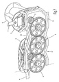
- Fig. 7 shows the detail analogous to FIG. 6, but with the gear housing 8 open, so that a part of the drive chain 12, consisting from the spur gears 6 and the pinions 5, is visible.
- the outer and inner mower discs are fitted at its periphery in a known manner with mowing blades 4, the outer contour during the rotation of the mower discs the flight circles 7 paint over.
- the drive chain 12 consists of the spur gears 6 and the pinions 5, wherein the pinions 5 have a drive shaft, which in the gear cover 9 of the transmission housing. 8 is stored and wherein the mower discs 2,3 with the respective pinion 5 form a rotationally fixed connection.
- the transmission side wall 11 of the gear housing 8 consists of a hollow profile 14, which, as shown in Fig. 7 and Fig. 8, the contour of the drive chain 12 following, this encloses.
- a detail of the cutter bar 1 according to FIG. 2, the view Y without the transmission pan bottom 15 is shown in Fig. 8.
- the hollow section 14 is shown as a rectangular hollow profile.
- the hollow section 14 may optionally be welded to either the gear cover 10 or the gear tray bottom, so that the gear tray bottom and gear cover, for example, can be bolted together. It is also possible that transmission tank bottom and gearbox cover are permanently welded together after mounting the transmission chain.
- the contour circles of Mähklingen cover a larger area than would be the case if the cutter bar at the front or rear a straight contour would have.
- FIG. 8 shows the view in FIG. 7 in a diametrical view
- FIGS. 9 and 10 show the mower according to FIG. 1 in a plan view without mowing disks
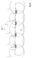
- 9 shows in an illustrative representation the undulating course of the front contour 16 and also a wave-shaped course of the rear contour 17 of the side wall 11 of the transmission housing 8.
- the hatched gain in sectional area 18.19 in the troughs 21 of the front contour 16 clearly, which of the circumferential mowing blades 4 lying within the contour circle 7, in addition to a straight line 20, which would form the end edge of a folded sheet metal housing, are covered and thus can be reached by the blades mähchnisch.
- FIG. 11 shows the section A-A through the cutter bar according to FIG. 4, wherein the transmission side wall 11 of the gear housing 8 is designed as a rectangular hollow profile 14.
- Figure 12 shows the section A-A through the cutter bar analogous to Figure 4, but with an alternative embodiment of the embodiment front side wall 11 as a hollow section 14 but with an oblique deflecting surface 22, which favors the sliding over of uneven floors by lower resistance forces.
- FIG. 13 shows the detail Z according to FIG. 12 in an enlarged view
- FIG. 14 shows the detail Z according to FIG. 12 in an enlarged representation, however, with an alternative embodiment of the front side wall configuration with a solid-walled cross-section 23.
- the gear cover 10 and the Transmission trough bottom 15 shown with the transmission side wall 11 by means of a rivet connection 24 as an embodiment of a possible connection technology.
- Gear tray bottom (15), and gear cover (10) are thus formed as a flat disc-shaped components which receive the transmission side wall (11) according to the sandwich construction between them.
- Transmission trough bottom (15), transmission side wall (11) and gear cover (10) can be formed as separate items that are detachably joined together, the transmission housing (8).
- the transmission pan (9) can also be releasably joined together with the transmission cover (10) the transmission housing (8) or alternatively the transmission trough bottom (15) and transmission side wall (11) also form a non-releasably interconnected unit as a transmission trough (9).
- gear cover (10) and the transmission side wall (11) form an inseparable unit which, however, together with the gear base (15) form a detachable unit.
- the transmission trough bottom (15), the transmission side wall (11) and the gear cover (10) may form separate individual parts which, when unsolvable, form the transmission housing (8).
- the insoluble compound may be, for example, a welded connection or a .Klebeharm or even a mixed compound of adhesive or riveting.
Landscapes
- Life Sciences & Earth Sciences (AREA)
- Environmental Sciences (AREA)
- Harvester Elements (AREA)
- Transition And Organic Metals Composition Catalysts For Addition Polymerization (AREA)
- Organic Low-Molecular-Weight Compounds And Preparation Thereof (AREA)
- Polyoxymethylene Polymers And Polymers With Carbon-To-Carbon Bonds (AREA)
Abstract
Description
- Die Erfindung betrifft einen Mähbalken für Scheibenmähwerke zur Verbesserung der Schnittqualität, insbesondere für die Grünfutterernte, in der Landwirtschaft gemäß dem Oberbegriff des unabhängigen Anspruchs 1.
- Derartige Mähwerke gibt es in vielfältigen Variationen, wie beispielsweise Heck-, Seiten-, Front- oder gezogene Mähwerke, oder Kombinationen aus vorgenannten Mähwerken und auch für selbstfahrende Mähwerke, oder auch für Direktfutterschneidwerke für Feldhäcksler.
- Bekannt sind Scheibenmähwerke mit umlaufenden Mähwerkzeugen, deren Mähklingen frei- bzw. schwenkbeweglich am Umfang der Mähscheiben an einem Zapfen aufgehängt sind. Die Mähklingen werden erst durch die Zentrifugalkraft stabilisiert und mähen das Grünfutter dann ohne Gegenschneide ab. Dabei sind die Mähscheiben antriebsseitig mit dem Motor eines Trägerfahrzeugs verbunden und zugleich in einer Antriebskette, bestehend aus Zahnrädern, welche unterhalb der Mähscheiben in einem geschlossenen Getriebegehäuse gelagert und untergebracht sind, eingebunden.
- Bekannt sind Getriebegehäuse, bestehend aus abgekanteten Stahlblechwannen mit einem verschraubten oder verschweißten oberen Getriebedeckel, indem die Getriebekette und die Mähscheiben gelagert sind. Durch die Fertigungstechnik des Abkantens sind die Stahlblechwannen in ihrer Längserstreckung als Prisma ausgebildet, welches den Nachteil beinhaltet, dass die Form des Getriebegehäuses durch eben diese Fertigungstechnik stark eingeschränkt ist..
- Dadurch bedingt sind beispielsweise die von den Flugkreisen der Messerklingen überdeckten Schnittflächen stärker eingeschränkt, als dieses zwingend notwendig wäre, so dass dieses das Mähbild insbesondere bei am Boden liegendem Grünfutter negativ beeinträchtigt, wodurch die unerwünschte Streifenbildung durch ungleichmäßige Stoppellänge im Mähbild gefördert wird.
- Die Erfindung befasst sich mit dem Problem, das Getriebegehäuse der Mähbalken von Scheibenmähwerke so auszugestalten, dass es in seiner Formgebung keinerlei Beschränkungen durch die Fertigungstechnik unterworfen ist.
- Gelöst wird die Aufgabe der Erfindung mit den kennzeichnenden Merkmalen des Anspruchs 1. Weitere vorteilhafte Ausgestaltungen der Erfindung sind den abhängigen Ansprüchen, der Beschreibung und den Figurendarstellungen zu entnehmen.
- Das Scheibenmähwerk nach der Erfindung besitzt ein Getriebegehäuse, dessen Getriebewannenboden und auch dessen Getriebewannendeckel frei von formgebenden Abkantungen ist. Da die Kaltverformung von Blechteilen beispielsweise durch Abkantung, Formstanzen oder Tiefziehen immer mit Fließvorgängen im Werkstoff über die Streckgrenze hinaus verbunden ist, ist der Werkstoff zumindest partiell in den Bereichen, indem es zur plastischen Verformung bedingt durch eben diese Fertigungstechnik bereits hinsichtlich seiner Festigkeit bereist geschwächt. Diese Fertigungstechnik kann durchaus auch innere Trennungen des Materials in Form von Mikrorissen zur Folge haben, welches die Dauerfestigkeit und die elastische Verformbarkeit des Materials erheblich beeinträchtigen kann und somit zu vorzeitigem Ausfall des Bauteils führen kann.
- Die erfindungsgemäße Ausgestaltung des Getriebegehäuses des Mähbalkens ist frei von derartigen Nachteilen und ist zudem in seiner Formgebung frei von allen Einschränkungen der Fertigungstechnik der Kaltverformung von Blechteilen, indem eben sowohl der Getriebewannenboden als auch der Getriebewannendeckel beispielsweise durch Laserschneiden aus einer Blechtafel herausgeschnitten werden kann und danach keiner Formveränderung mehr ausgesetzt wird. Dabei wird die umlaufende Seitenwand des Getriebegehäuses als separates Bauteil zwischen dem Getriebewannenboden und dem Getriebewannendeckel eingesetzt. Die Abdichtung gegen austretendes Getriebeöl kann entweder durch eingelegte plastisch verformbare Dichtstreifen erfolgen oder auch durch plastische aufspritzbare Dichtmasse, die zugleich als Dichtmasse und Kleber dient. Zusätzlich können alle Teile auch noch miteinander verschraubt oder vernietet sein.
- Bedingt durch die freie Formgebung kann dadurch auch eine vergrößerte Schnittfläche zum Mähen des Grünfutters am Boden und damit eine große Angriffsfläche für die Mähklingen erzeugt werden.
- Erreicht wird dieses, indem die vordere Kontur des Getriebegehäuses so ausgestaltet ist, dass die Zahnräder der Getriebekette möglichst eng von der Seitenwand wellenförmig umschlossen werden. Die damit einhergehende Schwächung des Flächenträgheitsmoments im Querschnitt des Getriebegehäuses kann durch eine verstärkte Seitenwand des Getriebegehäuses kompensiert werden. Bevorzugt ist daher die Seitenwand dabei als Hohlprofil ausgebildet. Das Hohlprofil kann dabei gleichzeitig als Kühlmittel führendes Element ausgebildet sein, welches dazu dienen kann, dem Getriebegehäuse die Abwärme des Getriebeöls zu entziehen, um somit die Lebensdauer des Getriebeöls zu erhöhen.
- Nähere Einzelheiten der Erfindung sind den nachfolgenden Figurendarstellungen und deren Beschreibungen zu entnehmen.
- Es zeigen:
- Fig. 1
- zeigt einen Mähbalken in einer Draufsicht mit offenem Getriebegehäuse, so dass die Antriebskette sichtbar ist
- Fig. 2
- zeigt den Mähbalken in einer Ansicht von hinten entgegen der Fahrtrichtung
- Fig. 3
- zeigt die Untenansicht des Mähbalkens
- Fig. 4
- zeigt einen Ausschnitt aus der Untenansicht gemäß Ansicht X des Mähbalkens der Fig. 2 in perspektivischer Ansicht
- Fig. 5
- zeigt den Ausschnitt analog Fig. 4, jedoch mit geöffnetem Getriebegehäuse, so dass ein Teil der Antriebskette sichtbar ist
- Fig. 6
- zeigt einen Ausschnitt aus der Untenansicht gemäß Ansicht Y des Mähbalkens der Fig. 2 in perspektivischer Ansicht
- Fig. 7
- zeigt den Ausschnitt analog Fig. 6, jedoch mit geöffnetem Getriebegehäuse, so dass ein Teil der Antriebskette sichtbar ist
- Fig. 8
- zeigt die Ansicht Fig. 7 in diametraler Ansicht
- Fig.9
- zeigt das Mähwerk gemäß Fig.1 in einer Draufsicht ohne Mähscheiben zur besseren Kenntlichmachung des wellenförmigen Verlaufs der Außenwand des Getriebegehäuses
- Fig.10
- zeigt das Mähwerk gemäß Fig.1 in einer Draufsicht ohne Mähscheiben in vereinfachter Darstellung mit Kenntlichmachung des Zugewinns an Schnittfläche
- Fig.11
- zeigt den Schnitt A-A durch den Mähbalken gemäß Fig.4
- Fig.12
- zeigt den Schnitt A-A durch den Mähbalken gemäß Fig.4, jedoch mit einer alternativen Ausführung der vorderen Seitenwandausgestaltung
- Fig.13
- zeigt die Einzelheit Z gemäß Fig.12 in vergrößerter Darstellung
- Fig.14
- zeigt die Einzelheit Z gemäß Fig.12 in vergrößerter Darstellung jedoch mit einer alternativen Ausführung der vorderen Seitenwandausgestaltung als vollwandiger Querschnitt
- In Fig. 1 ist ein Mähbalken 1 in einer Draufsicht mit offenem Getriebegehäuse 8 dargestellt, so dass die Antriebskette 12 mit den Stirnrädern 6 sichtbar ist. Das offene Getriebegehäuse 8 dient lediglich der besseren Sichtbarmachung und Beschreibung der Antriebskette 12, bestehend aus den in Reihe liegenden Stirnrädern 6 einschließlich der Zahnritzel zum Antrieb der Mähscheiben 2. Die Antriebskette 12 besteht somit aus den Stirnrädern 6 und den Ritzeln 5, welche antriebsseitig mit dem Motor eines Trägerfahrzeugs in Verbindung stehen.
- In Fig. 2 ist der Mähbalken 1 in einer Ansicht entgegen der Fahrtrichtung F von hinten, und in Fig. 3 die Untenansicht des Mähbalkens 1 dargestellt.
- In Fig. 4 ist ein Ausschnitt aus der Untenansicht gemäß Ansicht X des Mähbalkens 1 der Fig. 2 in perspektivischer Ansicht, und in Fig. 5 ist analog der Fig. 4 das Getriebegehäuse in geöffnetem Zustand, jedoch mit geöffnetem Getriebegehäuse dargestellt, so dass ein Teil der Antriebskette sichtbar ist. In Fig. 6 ist ein Ausschnitt aus der Untenansicht gemäß Ansicht Y des Mähbalkens der Fig. 2 in perspektivischer Ansicht dargestellt und Fig. 7 zeigt den Ausschnitt analog Fig. 6, jedoch mit geöffnetem Getriebegehäuse 8, so dass ein Teil der Antriebskette 12, bestehend aus den Stirnrädern 6 und den Ritzeln 5, sichtbar ist.
- Oberhalb des Mähbalkens 1 befinden sich in bekannter Anordnung die äußeren Mähscheiben 3 mit aufgesetzten Fördertrommeln 13 und den inneren Mähscheiben 2. Die äußeren und inneren Mähscheiben sind an ihrem Umfang in bekannter Weise mit Mähklingen 4 bestückt, deren äußere Kontur während des Umlaufs der Mähscheiben die Flugkreise 7 überstreichen. Die Antriebskette 12 besteht aus den Stirnrädern 6 und den Ritzeln 5, wobei die Ritzel 5 eine Antriebswelle aufweisen, welche im Getriebedeckel 9 des Getriebegehäuses 8 gelagert ist und wobei die Mähscheiben 2,3 mit dem jeweiligen Ritzel 5 eine drehfeste Verbindung eingehen.
- Die Getriebeseitenwand 11 des Getriebegehäuses 8 besteht aus einem Hohlprofil 14, welches wie in Fig. 7 bzw. Fig. 8 dargestellt, der Kontur der Antriebskette 12 folgend, diese umschließt. Dabei ist in Fig. 8 ein Ausschnitt aus dem Mähbalken 1 gemäß Fig. 2 die Ansicht Y ohne den Getriebewannenboden 15 dargestellt. In dem Ausführungsbeispiel ist das Hohlprofil 14 als Rechteckhohlprofil dargestellt. Das Hohlprofil 14 kann wahlweise entweder mit dem Getriebedeckel 10 oder mit dem Getriebewannenboden verschweißt sein, so dass Getriebewannenboden und Getriebedeckel beispielsweise miteinander verschraubt werden können. Möglich ist auch, dass Getriebewannenboden und Getriebewannendeckel nach der Montage der Getriebekette dauerhaft miteinander verschweißt werden. Dadurch bedingt, dass das Hohlprofil 14 als Getriebeseitenwand die Ritzel 5 und die Stirnräder 6 möglichst eng umschließt, können die Konturkreise der Mähklingen eine größere Fläche überdecken, als dieses der Fall wäre, wenn der Mähbalken an der Vorder- bzw. Hinterseite eine gerade verlaufende Kontur aufweisen würde.
- In Fig. 8 zeigt die Ansicht Fig. 7 in einer diametralen Ansicht und Fig.9 und Fig.10 zeigen das Mähwerk gemäß Fig.1 in einer Draufsicht ohne Mähscheiben. Fig.9 zeigt damit in anschaulicher Darstellung den wellenförmigen Verlauf der vorderen Kontur 16 und auch einen wellenförmigen Verlauf der hinteren Kontur 17 der Seitenwand 11 des Getriebegehäuses 8. Insbesondere in Fahrtrichtung F vor dem Getriebegehäuses 8 wird damit der schraffierte Zugewinn an Schnittfläche 18,19 in den Wellentälern 21 der vorderen Kontur 16 deutlich, welche von den umlaufenden Mähklingen 4 innerhalb der Konturkreises 7 liegend, zusätzlich gegenüber einer gerade verlaufenden Linie 20, welche die Abschlusskante eines abgekanteten Blechgehäuses bilden würde, überdeckt werden und somit von den Klingen mähtechnisch erreichbar sind.
- Fig.11 zeigt den Schnitt A-A durch den Mähbalken gemäß Fig.4, wobei die Getriebeseitenwand 11 des Getriebegehäuses 8 als Rechteck-Hohlprofil 14 ausgebildet ist. Fig.12 zeigt den Schnitt A-A durch den Mähbalken analog Fig.4, jedoch mit einer alternativen Ausführung der Ausgestaltung vorderen Seitenwand 11 als Hohlprofil 14 jedoch mit einer schrägen Abweisfläche 22, die das Übergleiten von Bodenunebenheiten durch geringere Wiederstandskräfte begünstigt. Fig.13 zeigt die Einzelheit Z gemäß Fig.12 in vergrößerter Darstellung und Fig.14 zeigt die Einzelheit Z gemäß Fig.12 in vergrößerter Darstellung jedoch mit einer alternativen Ausführung der vorderen Seitenwandausgestaltung mit einem vollwandiger Querschnitt 23. Dabei ist der Getriebedeckel 10 und der Getriebewannenboden 15 mit der Getriebeseitenwand 11 mittels einer Nietverbindung 24 als Ausführungsbeispiel einer möglichen Verbindungstechnik dargestellt.
- Getriebewannenboden (15), und Getriebedeckel (10) sind somit als planebene scheibenförmige Bauteile ausgebildet sind, welche die Getriebeseitenwand (11) nach der Sandwichbauweise zwischen sich aufnehmen.
- Getriebewannenboden (15), Getriebeseitenwand (11) und Getriebedeckel (10) können als separate Einzelteile ausgebildet, die lösbar zusammengefügt, das Getriebegehäuse (8) bilden.
- Wahlweise kann die Getriebewanne (9) auch lösbar zusammengefügt sein mit dem Getriebedeckel (10) das Getriebegehäuse (8) oder alternativ können Getriebewannenboden (15) und Getriebeseitenwand (11) ebenso eine unlösbar miteinander verbundene Einheit als Getriebewanne (9) bilden.
- Ebenso ist es auch möglich, dass Getriebedeckel (10) und Getriebeseitenwand (11) eine unlösbar miteinander verbundene Einheit bilden die aber mit dem Getriebeboden (15) wiederum eine lösbare Einheit bilden.
- In einer weiteren Ausgestaltungsmöglichkeit können Getriebewannenboden (15), Getriebeseitenwand (11) und Getriebedeckel (10) separate Einzelteile bilden, die unlösbar zusammengefügt, das Getriebegehäuse (8) bilden.
- Dabei kann die unlösbare Verbindung beispielsweise eine Schweissverbindung oder eine .Klebeverbindung sein oder auch eine Mischverbindung aus Klebeverbindung oder Vernietung sein.
-
- 1
- Mähbalken
- 2
- innere Mähscheibe
- 3
- äußere Mähscheibe
- 4
- Mähklinge
- 5
- Ritzel
- 6
- Stirnräder
- 7
- Flugkreis
- 8
- Getriebegehäuse
- 9
- Getriebewanne
- 10
- Getriebedeckel
- 11
- Getriebeseitenwand
- 12
- Antriebskette
- 13
- Fördertrommel
- 14
- Hohlprofil
- 15
- Getriebewannenboden
- 16
- vordere Kontur
- 17
- hintere Kontur
- 18
- Zugewinn an Schnittfläche
- 19
- Zugewinn an Schnittfläche
- 20
- gerade Linie
- 21
- Wellental
- 22
- schrägen Abweisfläche
- 23
- vollwandiger Querschnitt
- 24
- Nietverbindung
- F
- Fahrtrichtung
Claims (13)
- Scheibenmähwerk zum Anbau an ein Trägerfahrzeug, beispielsweise für einen Traktor oder für ein selbstfahrendes Trägerfahrzeug, mit mehreren um aufrechte Kreiselachsen umlaufend angetriebenen mit Mähklingen (4) besetzten Mähscheiben (2,3), die in einem Getriebegehäuse (8) eines Mähbalkens (1) unterhalb der Mähscheiben gelagert sind, und die von einer aus Zahnrädern gebildeten Antriebskette (12), welche sich innerhalb des Getriebegehäuses (8) befinden und in diesem gelagert sind, angetrieben werden, dadurch gekennzeichnet, dass Getriebewannenboden (15), und Getriebedeckel (10) als plattenförmige Bauteile ausgebildet sind, welche die Getriebeseitenwand (11) nach der Sandwichbauweise zwischen sich aufnehmen.
- Scheibenmähwerk nach Anspruch 1, dadurch gekennzeichnet, dass die Getriebeseitenwand (11) aus einem Hohlprofil besteht.
- Scheibenmähwerk nach Anspruch 2, dadurch gekennzeichnet, dass das Hohlprofil aus einem Rechteckholprofil besteht.
- Scheibenmähwerk nach Anspruch 1 bis 3, dadurch gekennzeichnet, dass Getriebewannenboden (15), Getriebeseitenwand (11) und Getriebedeckel (10) separate Einzelteile bilden, die lösbar zusammengefügt, das Getriebegehäuse (8) bilden.
- Scheibenmähwerk nach Anspruch 4, dadurch gekennzeichnet, dass die Getriebewanne (9) lösbar zusammengefügt mit dem Getriebedeckel (10) das Getriebegehäuse (8) bilden.
- Scheibenmähwerk nach Anspruch 1 bis 3, dadurch gekennzeichnet, dass Getriebewannenboden (15) und Getriebeseitenwand (11) eine unlösbar miteinander verbundene Einheit als Getriebewanne (9) bilden.
- Scheibenmähwerk nach Anspruch 1 bis 3, dadurch gekennzeichnet, dass Getriebedeckel (10) und Getriebeseitenwand (11) eine unlösbar miteinander verbundene Einheit bilden die mit dem Getriebeboden (15) eine lösbare Einheit bilden.
- Scheibenmähwerk nach Anspruch 1 bis 4, dadurch gekennzeichnet, dass Getriebewannenboden (15), Getriebeseitenwand (11) und Getriebedeckel (10) separate Einzelteile bilden, die unlösbar zusammengefügt, das Getriebegehäuse (8) bilden.
- Scheibenmähwerk nach Anspruch 8, dadurch gekennzeichnet, dass die unlösbare Verbindung eine Schweissverbindung darstellt.
- Scheibenmähwerk nach Anspruch 8, dadurch gekennzeichnet, dass die unlösbare Verbindung eine Klebeverbindung darstellt.
- Scheibenmähwerk nach Anspruch 8, dadurch gekennzeichnet, dass die unlösbare Verbindung eine Klebeverbindung in Verbindung mit einer Nietverbindung (24) darstellt.
- Scheibenmähwerk nach Anspruch 1 bis 11, dadurch gekennzeichnet, dass die Seitenwand 11 eine schräge Abweisfläche (22) aufweist.
- Scheibenmähwerk nach Anspruch 1 bis 12, dadurch gekennzeichnet, dass die Seitenwand 11 einen vollwandigen Querschnitt 23 aufweist.
Applications Claiming Priority (1)
| Application Number | Priority Date | Filing Date | Title |
|---|---|---|---|
| DE102005050188A DE102005050188A1 (de) | 2005-10-18 | 2005-10-18 | Scheibenmähwerk |
Publications (2)
| Publication Number | Publication Date |
|---|---|
| EP1776855A1 true EP1776855A1 (de) | 2007-04-25 |
| EP1776855B1 EP1776855B1 (de) | 2009-09-02 |
Family
ID=37596259
Family Applications (1)
| Application Number | Title | Priority Date | Filing Date |
|---|---|---|---|
| EP06021410A Not-in-force EP1776855B1 (de) | 2005-10-18 | 2006-10-12 | Scheibenmähwerk |
Country Status (3)
| Country | Link |
|---|---|
| EP (1) | EP1776855B1 (de) |
| AT (1) | ATE441317T1 (de) |
| DE (2) | DE102005050188A1 (de) |
Cited By (6)
| Publication number | Priority date | Publication date | Assignee | Title |
|---|---|---|---|---|
| FR2932949A1 (fr) * | 2008-06-26 | 2010-01-01 | Kuhn Audureau Sa | Tailleuse de haies perfectionnee |
| US8056307B2 (en) | 2009-10-05 | 2011-11-15 | Cnh America Llc | Mower cutterbar |
| EP2508061A1 (de) * | 2011-04-07 | 2012-10-10 | CLAAS Saulgau GmbH | Scheibenmähwerk |
| EP2250872B2 (de) † | 2009-05-11 | 2016-01-20 | Deere & Company | Erntemaschinenkopf mit einem mit Klebemittel befestigtem Rückblech |
| US10188030B2 (en) * | 2015-04-16 | 2019-01-29 | Deere & Company | Cutting mechanism for whole plant harvesting |
| EP4331338A1 (de) | 2022-08-30 | 2024-03-06 | Talex Spolka Z Ograniczona Opdowiedzialnoscia | Scheibenmähvorrichtung |
Families Citing this family (2)
| Publication number | Priority date | Publication date | Assignee | Title |
|---|---|---|---|---|
| DE102011016284B4 (de) | 2011-04-07 | 2022-11-10 | Claas Saulgau Gmbh | Scheibenmähwerk |
| DE102018128671A1 (de) * | 2018-11-15 | 2020-05-20 | Esm Ennepetaler Schneid- Und Mähtechnik Gmbh & Co. Kg | Portalschneidwerk |
Citations (2)
| Publication number | Priority date | Publication date | Assignee | Title |
|---|---|---|---|---|
| EP0965258A1 (de) * | 1998-06-18 | 1999-12-22 | Maschinenfabrik Bernard Krone GmbH | Mähmaschine |
| FR2840765A1 (fr) * | 2002-06-14 | 2003-12-19 | Kuhn Sa | Dispositif de coupe d'une faucheuse rotative comportant une fixation amelioree d'un organe de coupe |
-
2005
- 2005-10-18 DE DE102005050188A patent/DE102005050188A1/de not_active Withdrawn
-
2006
- 2006-10-12 AT AT06021410T patent/ATE441317T1/de active
- 2006-10-12 EP EP06021410A patent/EP1776855B1/de not_active Not-in-force
- 2006-10-12 DE DE502006004722T patent/DE502006004722D1/de active Active
Patent Citations (2)
| Publication number | Priority date | Publication date | Assignee | Title |
|---|---|---|---|---|
| EP0965258A1 (de) * | 1998-06-18 | 1999-12-22 | Maschinenfabrik Bernard Krone GmbH | Mähmaschine |
| FR2840765A1 (fr) * | 2002-06-14 | 2003-12-19 | Kuhn Sa | Dispositif de coupe d'une faucheuse rotative comportant une fixation amelioree d'un organe de coupe |
Cited By (7)
| Publication number | Priority date | Publication date | Assignee | Title |
|---|---|---|---|---|
| FR2932949A1 (fr) * | 2008-06-26 | 2010-01-01 | Kuhn Audureau Sa | Tailleuse de haies perfectionnee |
| EP2138031A3 (de) * | 2008-06-26 | 2010-08-11 | Kuhn-Audureau S.A. | Heckenschneider |
| EP2250872B2 (de) † | 2009-05-11 | 2016-01-20 | Deere & Company | Erntemaschinenkopf mit einem mit Klebemittel befestigtem Rückblech |
| US8056307B2 (en) | 2009-10-05 | 2011-11-15 | Cnh America Llc | Mower cutterbar |
| EP2508061A1 (de) * | 2011-04-07 | 2012-10-10 | CLAAS Saulgau GmbH | Scheibenmähwerk |
| US10188030B2 (en) * | 2015-04-16 | 2019-01-29 | Deere & Company | Cutting mechanism for whole plant harvesting |
| EP4331338A1 (de) | 2022-08-30 | 2024-03-06 | Talex Spolka Z Ograniczona Opdowiedzialnoscia | Scheibenmähvorrichtung |
Also Published As
| Publication number | Publication date |
|---|---|
| ATE441317T1 (de) | 2009-09-15 |
| DE502006004722D1 (de) | 2009-10-15 |
| EP1776855B1 (de) | 2009-09-02 |
| DE102005050188A1 (de) | 2007-06-14 |
Similar Documents
| Publication | Publication Date | Title |
|---|---|---|
| DE3149887C2 (de) | ||
| DE112011105538B4 (de) | Schnittmesser | |
| DE2722554A1 (de) | Maehmaschine | |
| DE3587411T2 (de) | Kreiselmäher. | |
| AT390162B (de) | Maehbalken mit um annaehernd senkrechte achsen umlaufenden scheiben | |
| DE2822686A1 (de) | Maehmaschine mit von unten angetriebenen scheiben | |
| CH617825A5 (de) | ||
| DE29900270U1 (de) | Messerblatt für ein Freischneidegerät | |
| EP1776855B1 (de) | Scheibenmähwerk | |
| DE20118336U1 (de) | Antriebsgetriebewellenaufbau eines Selbstfahr-Rasenmähers | |
| DE3317532C2 (de) | ||
| DE19521067A1 (de) | Mähscheibe mit Klingenbefestigung für Rotationsmähwerk | |
| DE2941293C2 (de) | ||
| DE102011016284B4 (de) | Scheibenmähwerk | |
| EP1353544B1 (de) | Schneid- und fördervorrichtung für ein reihenunabhängig arbeitendes schneidwerk | |
| DE10119915B4 (de) | Hydrodynamischer Momentwandler, insbesondere für Kraftfahrzeuge | |
| EP2508061B1 (de) | Scheibenmähwerk | |
| EP1776854B1 (de) | Scheibenmähwerk | |
| DE2935495A1 (de) | Maehmaschine mit von unten angetriebenen scheiben | |
| EP2508062B1 (de) | Scheibenmähwerk | |
| EP1369019B1 (de) | Scheibenmähwerk | |
| DE202021106204U1 (de) | Scheiben-Mähkopf | |
| AT409810B (de) | Scheibenmähwerk | |
| DE10145170C1 (de) | Messerwelle | |
| DE102010010368A1 (de) | Schneidvorrichtung für einen Granulator zum Schneiden von Granulat |
Legal Events
| Date | Code | Title | Description |
|---|---|---|---|
| PUAI | Public reference made under article 153(3) epc to a published international application that has entered the european phase |
Free format text: ORIGINAL CODE: 0009012 |
|
| AK | Designated contracting states |
Kind code of ref document: A1 Designated state(s): AT BE BG CH CY CZ DE DK EE ES FI FR GB GR HU IE IS IT LI LT LU LV MC NL PL PT RO SE SI SK TR |
|
| AX | Request for extension of the european patent |
Extension state: AL BA HR MK YU |
|
| 17P | Request for examination filed |
Effective date: 20071025 |
|
| AKX | Designation fees paid |
Designated state(s): AT BE BG CH CY CZ DE DK EE ES FI FR GB GR HU IE IS IT LI LT LU LV MC NL PL PT RO SE SI SK TR |
|
| 17Q | First examination report despatched |
Effective date: 20071217 |
|
| GRAP | Despatch of communication of intention to grant a patent |
Free format text: ORIGINAL CODE: EPIDOSNIGR1 |
|
| GRAS | Grant fee paid |
Free format text: ORIGINAL CODE: EPIDOSNIGR3 |
|
| GRAA | (expected) grant |
Free format text: ORIGINAL CODE: 0009210 |
|
| AK | Designated contracting states |
Kind code of ref document: B1 Designated state(s): AT BE BG CH CY CZ DE DK EE ES FI FR GB GR HU IE IS IT LI LT LU LV MC NL PL PT RO SE SI SK TR |
|
| REG | Reference to a national code |
Ref country code: CH Ref legal event code: EP |
|
| REG | Reference to a national code |
Ref country code: IE Ref legal event code: FG4D Free format text: LANGUAGE OF EP DOCUMENT: GERMAN |
|
| REF | Corresponds to: |
Ref document number: 502006004722 Country of ref document: DE Date of ref document: 20091015 Kind code of ref document: P |
|
| PG25 | Lapsed in a contracting state [announced via postgrant information from national office to epo] |
Ref country code: SE Free format text: LAPSE BECAUSE OF FAILURE TO SUBMIT A TRANSLATION OF THE DESCRIPTION OR TO PAY THE FEE WITHIN THE PRESCRIBED TIME-LIMIT Effective date: 20090902 Ref country code: LT Free format text: LAPSE BECAUSE OF FAILURE TO SUBMIT A TRANSLATION OF THE DESCRIPTION OR TO PAY THE FEE WITHIN THE PRESCRIBED TIME-LIMIT Effective date: 20090902 Ref country code: FI Free format text: LAPSE BECAUSE OF FAILURE TO SUBMIT A TRANSLATION OF THE DESCRIPTION OR TO PAY THE FEE WITHIN THE PRESCRIBED TIME-LIMIT Effective date: 20090902 |
|
| NLV1 | Nl: lapsed or annulled due to failure to fulfill the requirements of art. 29p and 29m of the patents act | ||
| LTIE | Lt: invalidation of european patent or patent extension |
Effective date: 20090902 |
|
| PG25 | Lapsed in a contracting state [announced via postgrant information from national office to epo] |
Ref country code: LV Free format text: LAPSE BECAUSE OF FAILURE TO SUBMIT A TRANSLATION OF THE DESCRIPTION OR TO PAY THE FEE WITHIN THE PRESCRIBED TIME-LIMIT Effective date: 20090902 Ref country code: NL Free format text: LAPSE BECAUSE OF FAILURE TO SUBMIT A TRANSLATION OF THE DESCRIPTION OR TO PAY THE FEE WITHIN THE PRESCRIBED TIME-LIMIT Effective date: 20090902 Ref country code: SI Free format text: LAPSE BECAUSE OF FAILURE TO SUBMIT A TRANSLATION OF THE DESCRIPTION OR TO PAY THE FEE WITHIN THE PRESCRIBED TIME-LIMIT Effective date: 20090902 Ref country code: PL Free format text: LAPSE BECAUSE OF FAILURE TO SUBMIT A TRANSLATION OF THE DESCRIPTION OR TO PAY THE FEE WITHIN THE PRESCRIBED TIME-LIMIT Effective date: 20090902 |
|
| PG25 | Lapsed in a contracting state [announced via postgrant information from national office to epo] |
Ref country code: CY Free format text: LAPSE BECAUSE OF FAILURE TO SUBMIT A TRANSLATION OF THE DESCRIPTION OR TO PAY THE FEE WITHIN THE PRESCRIBED TIME-LIMIT Effective date: 20090902 |
|
| REG | Reference to a national code |
Ref country code: IE Ref legal event code: FD4D |
|
| BERE | Be: lapsed |
Owner name: CLAAS SAULGAU G.M.B.H. Effective date: 20091031 |
|
| PG25 | Lapsed in a contracting state [announced via postgrant information from national office to epo] |
Ref country code: RO Free format text: LAPSE BECAUSE OF FAILURE TO SUBMIT A TRANSLATION OF THE DESCRIPTION OR TO PAY THE FEE WITHIN THE PRESCRIBED TIME-LIMIT Effective date: 20090902 Ref country code: CZ Free format text: LAPSE BECAUSE OF FAILURE TO SUBMIT A TRANSLATION OF THE DESCRIPTION OR TO PAY THE FEE WITHIN THE PRESCRIBED TIME-LIMIT Effective date: 20090902 Ref country code: IS Free format text: LAPSE BECAUSE OF FAILURE TO SUBMIT A TRANSLATION OF THE DESCRIPTION OR TO PAY THE FEE WITHIN THE PRESCRIBED TIME-LIMIT Effective date: 20100102 Ref country code: PT Free format text: LAPSE BECAUSE OF FAILURE TO SUBMIT A TRANSLATION OF THE DESCRIPTION OR TO PAY THE FEE WITHIN THE PRESCRIBED TIME-LIMIT Effective date: 20100104 Ref country code: IE Free format text: LAPSE BECAUSE OF FAILURE TO SUBMIT A TRANSLATION OF THE DESCRIPTION OR TO PAY THE FEE WITHIN THE PRESCRIBED TIME-LIMIT Effective date: 20090902 Ref country code: EE Free format text: LAPSE BECAUSE OF FAILURE TO SUBMIT A TRANSLATION OF THE DESCRIPTION OR TO PAY THE FEE WITHIN THE PRESCRIBED TIME-LIMIT Effective date: 20090902 Ref country code: ES Free format text: LAPSE BECAUSE OF FAILURE TO SUBMIT A TRANSLATION OF THE DESCRIPTION OR TO PAY THE FEE WITHIN THE PRESCRIBED TIME-LIMIT Effective date: 20091213 |
|
| PG25 | Lapsed in a contracting state [announced via postgrant information from national office to epo] |
Ref country code: SK Free format text: LAPSE BECAUSE OF FAILURE TO SUBMIT A TRANSLATION OF THE DESCRIPTION OR TO PAY THE FEE WITHIN THE PRESCRIBED TIME-LIMIT Effective date: 20090902 Ref country code: MC Free format text: LAPSE BECAUSE OF NON-PAYMENT OF DUE FEES Effective date: 20091031 |
|
| PLBE | No opposition filed within time limit |
Free format text: ORIGINAL CODE: 0009261 |
|
| STAA | Information on the status of an ep patent application or granted ep patent |
Free format text: STATUS: NO OPPOSITION FILED WITHIN TIME LIMIT |
|
| PG25 | Lapsed in a contracting state [announced via postgrant information from national office to epo] |
Ref country code: DK Free format text: LAPSE BECAUSE OF FAILURE TO SUBMIT A TRANSLATION OF THE DESCRIPTION OR TO PAY THE FEE WITHIN THE PRESCRIBED TIME-LIMIT Effective date: 20090902 |
|
| 26N | No opposition filed |
Effective date: 20100603 |
|
| PG25 | Lapsed in a contracting state [announced via postgrant information from national office to epo] |
Ref country code: GR Free format text: LAPSE BECAUSE OF FAILURE TO SUBMIT A TRANSLATION OF THE DESCRIPTION OR TO PAY THE FEE WITHIN THE PRESCRIBED TIME-LIMIT Effective date: 20091203 Ref country code: BE Free format text: LAPSE BECAUSE OF NON-PAYMENT OF DUE FEES Effective date: 20091031 |
|
| PG25 | Lapsed in a contracting state [announced via postgrant information from national office to epo] |
Ref country code: IT Free format text: LAPSE BECAUSE OF FAILURE TO SUBMIT A TRANSLATION OF THE DESCRIPTION OR TO PAY THE FEE WITHIN THE PRESCRIBED TIME-LIMIT Effective date: 20090902 Ref country code: BG Free format text: LAPSE BECAUSE OF FAILURE TO SUBMIT A TRANSLATION OF THE DESCRIPTION OR TO PAY THE FEE WITHIN THE PRESCRIBED TIME-LIMIT Effective date: 20091031 |
|
| PG25 | Lapsed in a contracting state [announced via postgrant information from national office to epo] |
Ref country code: LU Free format text: LAPSE BECAUSE OF NON-PAYMENT OF DUE FEES Effective date: 20091012 |
|
| REG | Reference to a national code |
Ref country code: CH Ref legal event code: PL |
|
| GBPC | Gb: european patent ceased through non-payment of renewal fee |
Effective date: 20101012 |
|
| PG25 | Lapsed in a contracting state [announced via postgrant information from national office to epo] |
Ref country code: HU Free format text: LAPSE BECAUSE OF FAILURE TO SUBMIT A TRANSLATION OF THE DESCRIPTION OR TO PAY THE FEE WITHIN THE PRESCRIBED TIME-LIMIT Effective date: 20100303 |
|
| PG25 | Lapsed in a contracting state [announced via postgrant information from national office to epo] |
Ref country code: CH Free format text: LAPSE BECAUSE OF NON-PAYMENT OF DUE FEES Effective date: 20101031 Ref country code: LI Free format text: LAPSE BECAUSE OF NON-PAYMENT OF DUE FEES Effective date: 20101031 |
|
| PG25 | Lapsed in a contracting state [announced via postgrant information from national office to epo] |
Ref country code: TR Free format text: LAPSE BECAUSE OF FAILURE TO SUBMIT A TRANSLATION OF THE DESCRIPTION OR TO PAY THE FEE WITHIN THE PRESCRIBED TIME-LIMIT Effective date: 20090902 Ref country code: GB Free format text: LAPSE BECAUSE OF NON-PAYMENT OF DUE FEES Effective date: 20101012 |
|
| REG | Reference to a national code |
Ref country code: FR Ref legal event code: PLFP Year of fee payment: 10 |
|
| REG | Reference to a national code |
Ref country code: FR Ref legal event code: PLFP Year of fee payment: 11 |
|
| PGFP | Annual fee paid to national office [announced via postgrant information from national office to epo] |
Ref country code: FR Payment date: 20161020 Year of fee payment: 11 Ref country code: DE Payment date: 20161020 Year of fee payment: 11 |
|
| PGFP | Annual fee paid to national office [announced via postgrant information from national office to epo] |
Ref country code: AT Payment date: 20161020 Year of fee payment: 11 |
|
| REG | Reference to a national code |
Ref country code: DE Ref legal event code: R119 Ref document number: 502006004722 Country of ref document: DE |
|
| REG | Reference to a national code |
Ref country code: AT Ref legal event code: MM01 Ref document number: 441317 Country of ref document: AT Kind code of ref document: T Effective date: 20171012 |
|
| REG | Reference to a national code |
Ref country code: FR Ref legal event code: ST Effective date: 20180629 |
|
| PG25 | Lapsed in a contracting state [announced via postgrant information from national office to epo] |
Ref country code: DE Free format text: LAPSE BECAUSE OF NON-PAYMENT OF DUE FEES Effective date: 20180501 |
|
| PG25 | Lapsed in a contracting state [announced via postgrant information from national office to epo] |
Ref country code: AT Free format text: LAPSE BECAUSE OF NON-PAYMENT OF DUE FEES Effective date: 20171012 Ref country code: FR Free format text: LAPSE BECAUSE OF NON-PAYMENT OF DUE FEES Effective date: 20171031 |
|
| P01 | Opt-out of the competence of the unified patent court (upc) registered |
Effective date: 20230511 |