EP1775453A2 - Steuerungssystem für eine Brennkraftmaschine - Google Patents
Steuerungssystem für eine Brennkraftmaschine Download PDFInfo
- Publication number
- EP1775453A2 EP1775453A2 EP06020473A EP06020473A EP1775453A2 EP 1775453 A2 EP1775453 A2 EP 1775453A2 EP 06020473 A EP06020473 A EP 06020473A EP 06020473 A EP06020473 A EP 06020473A EP 1775453 A2 EP1775453 A2 EP 1775453A2
- Authority
- EP
- European Patent Office
- Prior art keywords
- fuel
- condition
- engine
- wall surface
- fuel injection
- Prior art date
- Legal status (The legal status is an assumption and is not a legal conclusion. Google has not performed a legal analysis and makes no representation as to the accuracy of the status listed.)
- Withdrawn
Links
Images


Classifications
-
- F—MECHANICAL ENGINEERING; LIGHTING; HEATING; WEAPONS; BLASTING
- F02—COMBUSTION ENGINES; HOT-GAS OR COMBUSTION-PRODUCT ENGINE PLANTS
- F02D—CONTROLLING COMBUSTION ENGINES
- F02D35/00—Controlling engines, dependent on conditions exterior or interior to engines, not otherwise provided for
- F02D35/02—Controlling engines, dependent on conditions exterior or interior to engines, not otherwise provided for on interior conditions
- F02D35/028—Controlling engines, dependent on conditions exterior or interior to engines, not otherwise provided for on interior conditions by determining the combustion timing or phasing
-
- F—MECHANICAL ENGINEERING; LIGHTING; HEATING; WEAPONS; BLASTING
- F02—COMBUSTION ENGINES; HOT-GAS OR COMBUSTION-PRODUCT ENGINE PLANTS
- F02D—CONTROLLING COMBUSTION ENGINES
- F02D19/00—Controlling engines characterised by their use of non-liquid fuels, pluralities of fuels, or non-fuel substances added to the combustible mixtures
- F02D19/06—Controlling engines characterised by their use of non-liquid fuels, pluralities of fuels, or non-fuel substances added to the combustible mixtures peculiar to engines working with pluralities of fuels, e.g. alternatively with light and heavy fuel oil, other than engines indifferent to the fuel consumed
- F02D19/0602—Control of components of the fuel supply system
- F02D19/0607—Control of components of the fuel supply system to adjust the fuel mass or volume flow
- F02D19/061—Control of components of the fuel supply system to adjust the fuel mass or volume flow by controlling fuel injectors
-
- F—MECHANICAL ENGINEERING; LIGHTING; HEATING; WEAPONS; BLASTING
- F02—COMBUSTION ENGINES; HOT-GAS OR COMBUSTION-PRODUCT ENGINE PLANTS
- F02D—CONTROLLING COMBUSTION ENGINES
- F02D19/00—Controlling engines characterised by their use of non-liquid fuels, pluralities of fuels, or non-fuel substances added to the combustible mixtures
- F02D19/06—Controlling engines characterised by their use of non-liquid fuels, pluralities of fuels, or non-fuel substances added to the combustible mixtures peculiar to engines working with pluralities of fuels, e.g. alternatively with light and heavy fuel oil, other than engines indifferent to the fuel consumed
- F02D19/0626—Measuring or estimating parameters related to the fuel supply system
- F02D19/0634—Determining a density, viscosity, composition or concentration
- F02D19/0636—Determining a density, viscosity, composition or concentration by estimation, i.e. without using direct measurements of a corresponding sensor
-
- F—MECHANICAL ENGINEERING; LIGHTING; HEATING; WEAPONS; BLASTING
- F02—COMBUSTION ENGINES; HOT-GAS OR COMBUSTION-PRODUCT ENGINE PLANTS
- F02D—CONTROLLING COMBUSTION ENGINES
- F02D19/00—Controlling engines characterised by their use of non-liquid fuels, pluralities of fuels, or non-fuel substances added to the combustible mixtures
- F02D19/06—Controlling engines characterised by their use of non-liquid fuels, pluralities of fuels, or non-fuel substances added to the combustible mixtures peculiar to engines working with pluralities of fuels, e.g. alternatively with light and heavy fuel oil, other than engines indifferent to the fuel consumed
- F02D19/0639—Controlling engines characterised by their use of non-liquid fuels, pluralities of fuels, or non-fuel substances added to the combustible mixtures peculiar to engines working with pluralities of fuels, e.g. alternatively with light and heavy fuel oil, other than engines indifferent to the fuel consumed characterised by the type of fuels
- F02D19/0649—Liquid fuels having different boiling temperatures, volatilities, densities, viscosities, cetane or octane numbers
-
- F—MECHANICAL ENGINEERING; LIGHTING; HEATING; WEAPONS; BLASTING
- F02—COMBUSTION ENGINES; HOT-GAS OR COMBUSTION-PRODUCT ENGINE PLANTS
- F02D—CONTROLLING COMBUSTION ENGINES
- F02D35/00—Controlling engines, dependent on conditions exterior or interior to engines, not otherwise provided for
- F02D35/02—Controlling engines, dependent on conditions exterior or interior to engines, not otherwise provided for on interior conditions
- F02D35/023—Controlling engines, dependent on conditions exterior or interior to engines, not otherwise provided for on interior conditions by determining the cylinder pressure
-
- F—MECHANICAL ENGINEERING; LIGHTING; HEATING; WEAPONS; BLASTING
- F02—COMBUSTION ENGINES; HOT-GAS OR COMBUSTION-PRODUCT ENGINE PLANTS
- F02D—CONTROLLING COMBUSTION ENGINES
- F02D35/00—Controlling engines, dependent on conditions exterior or interior to engines, not otherwise provided for
- F02D35/02—Controlling engines, dependent on conditions exterior or interior to engines, not otherwise provided for on interior conditions
- F02D35/025—Controlling engines, dependent on conditions exterior or interior to engines, not otherwise provided for on interior conditions by determining temperatures inside the cylinder, e.g. combustion temperatures
-
- F—MECHANICAL ENGINEERING; LIGHTING; HEATING; WEAPONS; BLASTING
- F02—COMBUSTION ENGINES; HOT-GAS OR COMBUSTION-PRODUCT ENGINE PLANTS
- F02D—CONTROLLING COMBUSTION ENGINES
- F02D41/00—Electrical control of supply of combustible mixture or its constituents
- F02D41/0025—Controlling engines characterised by use of non-liquid fuels, pluralities of fuels, or non-fuel substances added to the combustible mixtures
-
- F—MECHANICAL ENGINEERING; LIGHTING; HEATING; WEAPONS; BLASTING
- F02—COMBUSTION ENGINES; HOT-GAS OR COMBUSTION-PRODUCT ENGINE PLANTS
- F02D—CONTROLLING COMBUSTION ENGINES
- F02D41/00—Electrical control of supply of combustible mixture or its constituents
- F02D41/02—Circuit arrangements for generating control signals
- F02D41/14—Introducing closed-loop corrections
- F02D41/1497—With detection of the mechanical response of the engine
-
- F—MECHANICAL ENGINEERING; LIGHTING; HEATING; WEAPONS; BLASTING
- F02—COMBUSTION ENGINES; HOT-GAS OR COMBUSTION-PRODUCT ENGINE PLANTS
- F02D—CONTROLLING COMBUSTION ENGINES
- F02D41/00—Electrical control of supply of combustible mixture or its constituents
- F02D41/30—Controlling fuel injection
- F02D41/38—Controlling fuel injection of the high pressure type
- F02D41/40—Controlling fuel injection of the high pressure type with means for controlling injection timing or duration
- F02D41/402—Multiple injections
-
- F—MECHANICAL ENGINEERING; LIGHTING; HEATING; WEAPONS; BLASTING
- F02—COMBUSTION ENGINES; HOT-GAS OR COMBUSTION-PRODUCT ENGINE PLANTS
- F02B—INTERNAL-COMBUSTION PISTON ENGINES; COMBUSTION ENGINES IN GENERAL
- F02B29/00—Engines characterised by provision for charging or scavenging not provided for in groups F02B25/00, F02B27/00 or F02B33/00 - F02B39/00; Details thereof
- F02B29/04—Cooling of air intake supply
- F02B29/0406—Layout of the intake air cooling or coolant circuit
-
- F—MECHANICAL ENGINEERING; LIGHTING; HEATING; WEAPONS; BLASTING
- F02—COMBUSTION ENGINES; HOT-GAS OR COMBUSTION-PRODUCT ENGINE PLANTS
- F02B—INTERNAL-COMBUSTION PISTON ENGINES; COMBUSTION ENGINES IN GENERAL
- F02B3/00—Engines characterised by air compression and subsequent fuel addition
- F02B3/06—Engines characterised by air compression and subsequent fuel addition with compression ignition
-
- F—MECHANICAL ENGINEERING; LIGHTING; HEATING; WEAPONS; BLASTING
- F02—COMBUSTION ENGINES; HOT-GAS OR COMBUSTION-PRODUCT ENGINE PLANTS
- F02D—CONTROLLING COMBUSTION ENGINES
- F02D2200/00—Input parameters for engine control
- F02D2200/02—Input parameters for engine control the parameters being related to the engine
- F02D2200/06—Fuel or fuel supply system parameters
- F02D2200/0611—Fuel type, fuel composition or fuel quality
- F02D2200/0612—Fuel type, fuel composition or fuel quality determined by estimation
-
- F—MECHANICAL ENGINEERING; LIGHTING; HEATING; WEAPONS; BLASTING
- F02—COMBUSTION ENGINES; HOT-GAS OR COMBUSTION-PRODUCT ENGINE PLANTS
- F02M—SUPPLYING COMBUSTION ENGINES IN GENERAL WITH COMBUSTIBLE MIXTURES OR CONSTITUENTS THEREOF
- F02M26/00—Engine-pertinent apparatus for adding exhaust gases to combustion-air, main fuel or fuel-air mixture, e.g. by exhaust gas recirculation [EGR] systems
- F02M26/02—EGR systems specially adapted for supercharged engines
- F02M26/04—EGR systems specially adapted for supercharged engines with a single turbocharger
- F02M26/05—High pressure loops, i.e. wherein recirculated exhaust gas is taken out from the exhaust system upstream of the turbine and reintroduced into the intake system downstream of the compressor
-
- F—MECHANICAL ENGINEERING; LIGHTING; HEATING; WEAPONS; BLASTING
- F02—COMBUSTION ENGINES; HOT-GAS OR COMBUSTION-PRODUCT ENGINE PLANTS
- F02M—SUPPLYING COMBUSTION ENGINES IN GENERAL WITH COMBUSTIBLE MIXTURES OR CONSTITUENTS THEREOF
- F02M26/00—Engine-pertinent apparatus for adding exhaust gases to combustion-air, main fuel or fuel-air mixture, e.g. by exhaust gas recirculation [EGR] systems
- F02M26/45—Sensors specially adapted for EGR systems
- F02M26/48—EGR valve position sensors
-
- Y—GENERAL TAGGING OF NEW TECHNOLOGICAL DEVELOPMENTS; GENERAL TAGGING OF CROSS-SECTIONAL TECHNOLOGIES SPANNING OVER SEVERAL SECTIONS OF THE IPC; TECHNICAL SUBJECTS COVERED BY FORMER USPC CROSS-REFERENCE ART COLLECTIONS [XRACs] AND DIGESTS
- Y02—TECHNOLOGIES OR APPLICATIONS FOR MITIGATION OR ADAPTATION AGAINST CLIMATE CHANGE
- Y02T—CLIMATE CHANGE MITIGATION TECHNOLOGIES RELATED TO TRANSPORTATION
- Y02T10/00—Road transport of goods or passengers
- Y02T10/10—Internal combustion engine [ICE] based vehicles
- Y02T10/30—Use of alternative fuels, e.g. biofuels
-
- Y—GENERAL TAGGING OF NEW TECHNOLOGICAL DEVELOPMENTS; GENERAL TAGGING OF CROSS-SECTIONAL TECHNOLOGIES SPANNING OVER SEVERAL SECTIONS OF THE IPC; TECHNICAL SUBJECTS COVERED BY FORMER USPC CROSS-REFERENCE ART COLLECTIONS [XRACs] AND DIGESTS
- Y02—TECHNOLOGIES OR APPLICATIONS FOR MITIGATION OR ADAPTATION AGAINST CLIMATE CHANGE
- Y02T—CLIMATE CHANGE MITIGATION TECHNOLOGIES RELATED TO TRANSPORTATION
- Y02T10/00—Road transport of goods or passengers
- Y02T10/10—Internal combustion engine [ICE] based vehicles
- Y02T10/40—Engine management systems
Definitions
- the present invention relates to a control system for an internal combustion engine, and particularly, to a control system for a compression ignition internal combustion engine which burns an air-fuel mixture in a combustion chamber by compressing the air-fuel mixture.
- JP '818 discloses a control system for a compression ignition internal combustion engine in which premix combustion is performed. According to the control system disclosed by JP '818, an actual ignition timing of fuel is detected during the premix combustion, and the properties of the fuel in use are determined according to an ignition timing error and differences in the ignition timing errors, the ignition timing error being a difference between the actual ignition timing and a previously set reference ignition timing.
- the engine operating region where the premix combustion is performed, is, for example, a hatched region shown in FIG. 10.
- the hatched region is comparatively narrow relative to the entire engine operating region. Therefore, an execution timing in determining the fuel property is delayed, wherein the fuel injection is performed at a timing not suitable in view of the fuel property, such that a misfire may occur.
- the present invention was attained in view of the above-described point, and an aspect of the present invention is to provide a control system for an internal combustion engine which quickly and accurately determines a property, i.e., the cetane number, of the fuel in use.
- the present invention provides a control system for an internal combustion engine having a fuel injection means for injecting fuel to a combustion chamber of the engine and burning the fuel by compressing an air-fuel mixture in the combustion chamber.
- the control system includes condition detecting means, fuel injection control means, operation control means, and cetane number estimating means.
- the condition detecting means detects an operating condition (TE, TOIL, TW) of the engine and/or a refueling condition of a fuel tank which supplies fuel to the engine.
- the fuel injection control means controls the fuel injection means.
- the operation control means changes at least one operating parameter (NINJ, CAIM) of the engine when at least one of the operating condition and the refueling condition, detected by the condition detecting means, satisfies a predetermined condition in a predetermined low load operating condition of the engine.
- the cetane number estimating means estimates a cetane number (CET) of the fuel in use according to an ignition timing (CAFM) of the fuel detected after changing the at least one engine operating parameter.
- the at least one engine operating parameter when at least one of the detected engine operating condition and the refueling condition satisfies the predetermined condition in the predetermined low load operating condition of the engine, the at least one engine operating parameter is changed and the cetane number of the fuel in use is estimated according to the ignition timing of the fuel detected after changing the at least one engine operating parameter.
- the cetane number estimation is performed in the predetermined low load operating condition. Consequently, the cetane number of the fuel in use can be determined quickly and accurately.
- the fuel injection control means performs a plurality of fuel injections for each, that is, one, combustion cycle in each, that is, one, cylinder, and the operation control means decreases the number of fuel injections that are performed when the predetermined condition is satisfied.
- the operation control means changes a timing (CAIM) of the fuel injection performed by the fuel injection means when the predetermined condition is satisfied.
- CAIM timing of the fuel injection performed by the fuel injection means
- the fuel injection timing when the predetermined conditions are satisfied, the fuel injection timing is changed.
- the change in the fuel injection timing increases an amount of change in the ignition timing due to the difference in the cetane number, thereby improving the accuracy of the estimated cetane number.
- control system further includes wall surface temperature condition determining means for determining a wall surface temperature condition, wherein a wall surface temperature (TWALL) of the combustion chamber is in a predetermined temperature range (TWALL ⁇ TWLTH) during a predetermined low load operating condition.
- the predetermined condition includes the wall surface temperature condition.
- the wall surface temperature condition wherein the wall surface temperature of the combustion chamber in the predetermined low load operating condition
- the cetane number estimation is performed when the wall surface temperature condition is satisfied.
- the wall surface temperature of the combustion chamber becomes high and the ignition timing shifts in the advancing direction compared with the normal condition. Therefore, estimation of the cetane number cannot accurately be performed.
- the wall surface temperature condition determining means includes initial wall surface temperature estimating means and gradually reducing means.
- the initial wall surface temperature estimating means estimates an initial wall surface temperature (TWALL) based on the engine operating condition immediately before the engine operating condition shifts to the predetermined low load operating condition.
- the gradually reducing means gradually reduces the initial wall surface temperature (TWALL) after the engine operating condition shifts to the predetermined low load operating condition.
- the wall surface temperature condition determining means determines that the wall surface temperature condition is satisfied when the temperature output from the gradually reducing means is in the predetermined temperature range.
- the initial wall surface temperature is estimated immediately before the engine operating condition shifts to the predetermined low load operating condition.
- the estimated wall surface temperature is obtained by gradually reducing the initial wall surface temperature after the engine operating condition shifts to the predetermined low load operating condition.
- the wall surface temperature condition is determined to be satisfied. Therefore, the wall surface temperature condition is accurately determined according to the engine operating condition immediately before shifting to the predetermined low load operating condition.
- the wall surface temperature condition determining means includes initial wall surface temperature estimating means and waiting time period setting means.
- the initial wall surface temperature estimating means estimates an initial wall surface temperature (TWALL) based on the engine operating condition immediately before the engine operating condition shifts to the predetermined low load operating condition.
- the waiting time period setting means sets a waiting time period (TWAIT) according to the wall surface temperature.
- the waiting time period is a time period extending from the time the engine operating condition shifts to the predetermined low load operating condition to the time the wall surface temperature condition is satisfied.
- the wall surface temperature condition determining means determines the wall surface temperature condition is satisfied when the waiting time period has elapsed from the time the engine operating condition shifts to the predetermined low load operating condition.
- the initial wall surface temperature is estimated according to the engine operating condition immediately before the engine operating condition shifts to the predetermined low load operating condition.
- the waiting time period from shifting to the predetermined low load operating condition to the satisfaction of the wall surface temperature condition is set according to the initial wall surface temperature.
- the wall surface temperature condition is determined to be satisfied. If the elapsed waiting time period reaches the set waiting time period, the wall surface temperature is considered to be in the predetermined temperature range. Consequently, the wall surface temperature condition is accurately determined according to the engine operating condition immediately before the shift to the predetermined low load operating condition.
- the operation control means reduces a target engine rotational speed in the predetermined low load operating condition and/or reduces an intake air flow rate of the engine.
- the present invention further provides another control system for an internal combustion engine having a fuel injection means for injecting fuel into a combustion chamber of the engine and burning the injected fuel by compressing an air-fuel mixture in the combustion chamber.
- the control system includes fuel injection control means, actual ignition timing detecting means, and cetane number estimating means.
- the fuel injection control means controls the fuel injection means.
- the actual ignition timing detecting means detects an actual ignition timing of the fuel injected by the fuel injection means.
- the cetane number estimating means estimates a cetane number of the fuel in use according to the detected ignition timing.
- the fuel injection control means sets a fuel injection timing (CAIM) of the fuel injection means so that a difference ( ⁇ CACET) in the actual ignition timings due to a difference in cetane numbers of the fuel is equal to or greater than a predetermined value ( ⁇ CATH) when the cetane number estimating means performs the cetane number estimation.
- CAIM fuel injection timing
- the fuel injection timing is set so that the difference in the actual ignition timings due to the difference in cetane numbers of the fuel is equal to or greater than the predetermined value. Accordingly, the cetane number of the fuel is accurately estimated.
- the fuel injection control means sets the fuel injection timing (CAIM) of the fuel injection means so that an amount (THC) of hydrocarbon emitted from the engine is equal to or less than a predetermined amount (THCLH) when the cetane number estimating means performs the cetane number estimation.
- CAIM fuel injection timing
- the fuel injection timing is set so that the amount of hydrocarbon emitted from the engine is equal to or less than the predetermined amount. Accordingly, the emission amount of hydrocarbon is suppressed.
- the fuel injection control means sets the fuel injection timing (CAIM) of the fuel injection means in a range of the crank angle from 20 to 25 degrees before a crank angle at which a piston corresponding to the combustion chamber reaches the top dead center.
- CAIM fuel injection timing
- the fuel injection is set in the range of the crank angle from 20 to 25 degrees before the crank angle at which the piston reaches the top dead center when performing the cetane number estimation. Accordingly, the cetane number estimation is accurately performed while suppressing the emission amount of hydrocarbon.
- FIG. 1 is a schematic diagram showing an internal combustion engine and a control system therefor according to a first embodiment of the present invention
- FIG. 2 shows a configuration of a part of the control system shown in FIG. 1;
- FIG. 3 is a flowchart showing a method of estimating the cetane number of the fuel in use
- FIG. 4 is a block diagram showing a configuration of an ignition timing calculation module
- FIG. 5 is a time chart illustrating the band pass filtering of the cylinder pressure sensor output
- FIGs. 6A-6B show time charts used for detecting the ignition timing
- FIG. 7 shows a table for calculating the cetane number (CET) from the ignition delay time period (TDFM);
- FIG. 8 is a flowchart showing a modification of the process shown in FIG. 3;
- FIGs. 9A-9B show relationships between the intake air flow rate (GA) and the ignition timing (CAFM);
- FIG. 10 shows a premix combustion region
- FiGs. 11A-11 B show changes in the heat release rate (HRR) in a specific cylinder
- FIG. 12 is a time chart illustrating a problem that arises when the high load operation is performed before shifting to the idling condition
- FIG. 13 is a flowchart showing a method of the cetane number estimation process according to a second embodiment of the present invention.
- FIG. 14 is a flowchart showing a modification of the process shown in FIG 3;
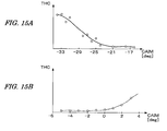
- FIGs. 15A-15B show relationships between the fuel injection timing (CAIM) and an amount (THC) of HC emission;
- FIGs. 16A-16B show relationships between the fuel injection timing (CAIM) and the actual ignition timing (CAFM'); and
- FIG. 17 illustrates a setting range (R0) of the fuel injection timing that is suitable for the cetane number estimation process.
- FiGs. 1 and 2 are schematic diagrams showing a configuration of an internal combustion engine and a control system therefor according to a first embodiment of the present invention.
- the internal combustion engine 1 (hereinafter referred to as "engine") is a diesel engine wherein fuel is injected directly into the cylinders.
- Each cylinder is provided with a fuel injection valve 6 electrically connected to an electronic control unit 4 (hereinafter referred to as "ECU 4").
- the ECU 4 controls a valve opening timing and a valve opening period of each fuel injection valve 6. That is, the fuel injection timing and fuel injection period are controlled by the ECU 4.
- the engine 1 has an intake pipe 7, an exhaust pipe 8, and a turbocharger 9.
- the turbocharger 9 includes a turbine and a compressor connected to the turbine through a shaft. The turbine is rotationally driven by the kinetic energy of exhaust gases. The turbocharger 9 pressurizes (compresses) the intake air of the engine 1.
- An intercooler 21 is provided downstream of the compressor in the intake pipe 7, and a throttle valve 22 is provided downstream of the intercooler 21.
- the throttle valve 22 is configured to be opened and closed by an actuator 23 connected to the ECU 4. Accordingly, the ECU 4 controls opening of the throttle valve 22 through the actuator 23.
- An exhaust gas recirculation passage 25 for recirculating exhaust gases to the intake pipe 7 is provided between the exhaust pipe 8 and the intake pipe 7.
- the exhaust gas recirculation passage 25 is provided with an exhaust gas recirculation valve 26 (hereinafter referred to as "EGR valve") that controls the amount of exhaust gases that are recirculated.
- the EGR valve 26 is an electromagnetic valve having a solenoid.
- a valve opening of the EGR valve 26 is controlled by the ECU 4.
- the EGR valve 26 is provided with a lift sensor 27 for detecting the valve opening (valve lift) LACT of the EGR valve 26, wherein a detection signal of the lift sensor 27 is supplied to the ECU 4.
- the exhaust gas recirculation passage 25 and the EGR valve 26 define an exhaust gas recirculation mechanism.
- the intake pipe 7 is provided with an intake air flow rate sensor 31 for detecting an intake air flow rate GA, a boost pressure sensor 32 for detecting an intake pressure (boost pressure) PB on the downstream side of the compressor, and an intake pressure sensor 33 for detecting an intake pressure PI.
- the exhaust pipe 8 is provided with an exhaust gas temperature sensor 34 for detecting an exhaust gas temperature TE.
- the sensors 31 to 34 are connected to the ECU 4. The detection signals of the sensors 31 to 34 are supplied to the ECU 4.
- a catalytic converter 28 and a particulate filter 29 are provided downstream of the turbine in the exhaust pipe 8.
- the catalytic converter 28 accelerates oxidization of hydrocarbon, and the like, in the exhaust gases, and the particulate filter 29 traps particulate matter which mainly consists of soot.
- Each cylinder of the engine 1 is provided with a cylinder pressure sensor 2 for detecting a cylinder pressure, i.e., a pressure in the combustion chamber of the engine 1.
- the cylinder pressure sensor 2 is configured in one body together with the spark plug disposed in each cylinder.
- the detection signal of the cylinder pressure sensor 2 is supplied to the ECU 4. It is to be noted that the detection signal of the cylinder pressure sensor 2 corresponds to a differential signal of the cylinder pressure PCYL with respect to the crank angle (time), and the cylinder pressure PCYL is obtained by integrating the output of the cylinder pressure sensor.
- the engine 1 is provided with a crank angle position sensor 3 for detecting a rotation angle of the crankshaft (not shown).
- the crank angle position sensor 3 generates one pulse at every 1 degree of the crank angle, wherein the pulse signal is then supplied to the ECU 4.
- the crank angle position sensor 3 further generates a cylinder discrimination pulse at a predetermined crank angle of a specific cylinder of the engine 1 and supplies the cylinder discrimination pulse to the ECU 4.
- An accelerator sensor 35 for detecting an operation amount AP of the accelerator pedal of the vehicle driven by the engine 1 a coolant temperature sensor 36 for detecting a coolant temperature TW of the engine 1, an oil temperature sensor 37 for detecting a lubricating oil temperature TOIL of the engine 1, an oxygen concentration sensor (not shown) for detecting an oxygen concentration in the exhaust gases, an intake air temperature sensor (not shown) for detecting an intake air temperature TA of the engine 1, and the like, are connected to the ECU 4.
- the detection signals of the sensors 35-37 are supplied to the ECU 4.
- the ECU 4 supplies a control signal of the fuel injection valve 6 provided in the combustion chamber of each cylinder of the engine 1 to a drive circuit 5.
- the drive circuit 5 is connected to the fuel injection valve 6 and supplies drive signals to the fuel injection valve 6 according to the control signal from the ECU 4. Fuel is thereby injected into the combustion chamber of each cylinder at the fuel injection timing in accordance with the control signal output from the ECU 4.
- the ECU 4 normally perfoms a pilot injection and a main injection in each cylinder.
- the ECU 4 includes an amplifier 10, an A/D conversion block 11, a pulse generation block 13, a CPU 14 (Central Processing Unit), a ROM 15 (Read Only Memory) for storing programs executed by the CPU 14, a RAM 16 (Random Access Memory) for storing calculation results, etc., an input circuit 17, and an output circuit 18.
- the detection signal of the cylinder pressure sensor 2 is input to the amplifier 10.
- the amplifier 10 amplifies the input signal.
- the signal amplified by the amplifier 10 is input to the A/D conversion block 11.
- the pulse signal output from the crank angle position sensor 3 is input to the pulse generation block 13.
- the A/D conversion block 11 which includes a buffer 12, converts the cylinder pressure sensor output from the amplifier 10 to a digital value dp/d ⁇ (hereinafter referred to as "pressure change rate"), and stores the converted digital value in the buffer 12.
- a pulse signal PLS1 (hereinafter referred to as "one-degree pulse”) having a crank angle period of one degree is supplied to the A/D conversion block 11 from the pulse generation block 13, the cylinder pressure sensor output is sampled at the intervals of the one-degree pulse PLS1 to be converted to a digital value, and the digital value is stored in the buffer 12.
- a pulse signal PLS6 having a crank angle period of six degrees is supplied to the CPU 14 from the pulse generation block 13.
- the CPU 14 performs a process for reading the digital value stored in the buffer 12 at intervals of the six-degree pulse PLS6. That is, in the present embodiment, the A/D conversion block 11 does not request an interrupt to the CPU 14, but the CPU 14 performs the reading process at intervals of the six-degree pulse PLS6.
- the input circuit 17 converts the detection signals from various sensors to digital values and supplies the digital values to the CPU 14.
- An engine rotational speed NE is calculated from the time period of the six-degree pulse PLS6.
- a demand torque TRQ of the engine 1 is calculated according to the operation amount AP of the accelerator pedal.
- the CPU 14 outputs control signals for controlling the throttle valve 22, the EGR valve 26, and the like, according to the engine operating condition through the output circuit 18. Further, the CPU 14 executes a process for estimating a cetane number of the fuel in use, as described below, and performs the fuel injection control according to the estimated cetane number.
- FIG. 3 is a flowchart showing a method of estimating a cetane number.
- step S11 it is determined whether the engine 1 is in the idling condition. If the answer to step S11 is affirmative (YES), it is determined whether a predetermined execution condition for stably performing the cetane number estimation is satisfied.
- the predetermined execution condition is satisfied, for example, when the exhaust temperature TE is equal to or greater than a predetermined temperature TE0 (e.g., about 90 degrees Centigrade) and the coolant temperature TW or the lubricating oil temperature TOIL, which indicates the warm-up condition of the engine 1, is equal to or greater than a predetermined temperature TWUP (e.g., 80 degrees Centigrade).
- a predetermined temperature TE0 e.g., about 90 degrees Centigrade
- TWUP e.g. 80 degrees Centigrade
- step S11 or S12 If the answer to step S11 or S12 is negative (NO), the process immediately ends without performing the cetane number estimation.
- step S12 If the predetermined execution condition is satisfied in step S12, the pilot injection is stopped and the single injection (only the main injection) is performed (step S13). That is, a number NINJ of fuel injections per 1 cylinder per 1 cycle is set to "1". Further, the main injection timing is changed in the advancing direction with respect to the normal injection timing (step S14). By changing the double injection to single injection and advancing the fuel injection timing with respect to the normal timing as described above, a difference in the ignition timing due to the difference in the cetane numbers is easily detected.
- step S15 a CAFMM map (not shown) is retrieved according to the engine rotational speed NE and the demand torque TRQ to calculate a reference ignition timing CAFMM.
- the CAFMM map is set based on a fuel of a high cetane number (e.g., 57).
- step S16 an ignition delay angle DCA is calculated by subtracting an actual ignition timing CAFM from the reference ignition timing CAFMM.
- FIG. 4 is a block diagram showing a configuration of an ignition timing calculation module which calculates (detects) an actual ignition timing CAFM.
- the function of the ignition timing calculation module is realized by the process executed by the CPU 14.
- the ignition timing calculation module includes a band pass filtering block 71, a phase delay correction block 72, and an ignition timing determination block 73.
- the pressure change rate dp/d ⁇ output from the cylinder pressure sensor 2 is input to the band pass filtering block 71.
- the waveform W1 shows an input waveform
- the waveform W2 shows an output waveform.
- the phase delay which occurs in the band pass filtering block 71 is corrected in the phase delay correction block 72.
- the ignition timing determination block 73 determines that a crank angle position, at which the pressure change rate dp/d ⁇ takes a peak value corresponding to the fuel injection, is the actual ignition timing CAFM. Specifically as shown in FIG. 6B, the crank angle position, at which the pressure change rate dp/d ⁇ output from the phase delay correction block 72 exceeds a detection threshold value DPP, is determined to be the actual ignition timing CAFM.
- FIGs. 6A and 6B an injection pulse INJM started from a crank angle position CAIM is shown.
- FIG. 6B shows an angle position range RDET (e.g., 10 degrees) where the actual ignition timing CAFM is detected.
- the detection angle position range RDET e.g. 10 degrees
- the ignition timing is accurately determined without increasing calculation load of the CPU 14.
- step S17 the ignition delay angle position DCA is converted to an ignition delay time period TDFM using the engine rotational speed NE.
- a CET table which is shown in FIG. 7, is retrieved according to the ignition delay time period TDFM to calculate the cetane number CET.
- the fuel injection timing is changed in the advancing direction and the fuel injection is changed from the double injection to the single injection. Accordingly, the cetane number can be estimated in the idling condition, thereby quickly and accurately determining the cetane number of the fuel in use.
- FIGs. 11A-11 B show changes in the heat release rate HRR in the specific cylinder of the engine 1.
- the solid line corresponds to the fuel of a high cetane number (e.g., 57), and the dashed line corresponds to the fuel of a low cetane number (e.g., 41).
- the horizontal axis represents the crank angle CA wherein the crank angle CA is set to "0" when the piston is at the top dead center.
- FIG. 11A corresponds to a case where pilot and main injections are performed. In this case, the fuel injection is performed in the vicinity of zero degree of the crank angle (the top dead center), and the heat release rate HRR reaches a peak value at 5 to 10 degrees after the top dead center.
- the difference in the peak positions due to the difference in the cetane numbers is about 1 degree.
- FIG. 11 B corresponds to a case where only the main injection is performed at an advanced fuel injection timing. In this case, the fuel injection is performed in the vicinity of -20 degrees of the crank angle (20 degrees before the top dead center), and the heat release rate HRR reaches a peak value at 5 to 10 degrees before the top dead center.
- the difference in the peak positions due to the difference in the cetane numbers is about 8 degrees. That is, by performing only the main injection (single injection) and advancing the injection timing, the difference in the ignition timings due to the difference in cetane numbers becomes significant which improves the calculation accuracy of the cetane number CET.
- the amount of hydrocarbon (HC) in exhaust gases tends to increase compared with the case where two or more injections are performed.
- a stuck fault of the EGR valve 26, blockage of the catalytic converter 28, and the like become more likely to occur.
- the predetermined execution condition include a condition wherein the exhaust temperature TE is equal to or greater than a predetermined temperature TE0.
- the fuel injection valve 6 corresponds to the fuel injection means.
- the exhaust temperature sensor 34, the coolant temperature sensor 36, and the oil sensor 37 correspond to the condition detecting means.
- the ECU 4 forms the fuel injection control means, the operation control means, and the cetane number estimation means.
- the normal fuel injection control (not shown) performed by the ECU 4 corresponds to the fuel injection control means.
- Steps S13 and S14 of FIG. 3 correspond to the operation control means
- steps S14 to S17 correspond to the cetane number estimation means.
- FIG. 8 is a flowchart showing a modification of the above-described process of FIG. 3.
- step S21 is added between steps S14 and S15.
- step S21 one or more other operating parameters are changed. Specifically, any one, two, or all of the three steps described below are executed:
- Step 1 includes reducing the target engine rotational speed in the idling condition by about 100 rpm, for example;
- Step 2 includes controlling the throttle valve 22 in the closing direction to decrease the intake air flow
- Step 3 includes closing the EGR valve 26.
- the difference in the actual ignition timings CAFM due to the difference in the cetane numbers becomes significant, and the estimation accuracy of the cetane number is improved.
- the throttle valve 22 When executing the above-described step 2, the throttle valve 22 is closed so that the detected intake air flow rate GA coincides with a desired value. Alternatively, a throttle valve opening TH is detected, and the throttle valve 22 is closed so that the detected throttle valve opening TH coincides with a predetermined opening.
- FIG. 9A is a graph showing a relationship between the intake air flow rate GA and the actual ignition timing CAFM.
- the square marks correspond to the fuel of cetane number "41”
- the round marks correspond to the fuel of cetane number "57”.
- the intake air flow rate GA is equal to a first value GA1
- the difference in the ignition timings is about 6 degrees.
- the difference in the ignition timings can be increased to about 10 degrees by decreasing the intake air flow rate GA to a second value GA2.
- Step S21 in the above-described modification corresponds to a portion of the operation control means.
- a condition of immediately after refueling may be included in the predetermined execution condition in step S12. That is, the cetane number estimation may not be performed unless the condition of immediately after refueling is satisfied, and the cetane number estimation may be performed only immediately after refueling.
- the condition of immediately after refueling is determined based on an increase in the indicated value of the fuel gauge, or opening and closing of the filler cap, and a change from an OFF state to an ON state of the engine switch.
- sensors (not shown) for determining whether the condition of immediately after refueling is satisfied are contained in the state detecting means.
- condition of the exhaust temperature TE, the coolant temperature TW, or the oil temperature TOIL may be removed from the above-described predetermined execution condition, and only the condition of immediately after refueling may be used as the predetermined execution condition.
- step S21 any one, or both, of steps 1 and 2 described below are performed:
- Step 1 includes reducing the target engine rotational speed in the idling condition by about 100 rpm, for example.
- Step 2 includes controlling the EGR valve 26 in the opening direction to decrease the intake air flow rate GA.
- FIG. 9B is a graph showing a relationship between the intake air flow rate GA and the actual ignition timing CAFM.
- the square marks correspond to the fuel of cetane number "41" and the round marks correspond to the fuel of cetane number "57”.
- the intake air flow rate GA is equal to the first value GA1
- the difference in the ignition timings is about 6 degrees.
- the difference in the ignition timings is increased 8 degrees by opening the EGR valve 26 to decrease intake air flow rate GA to the second value GA2.
- the process for executing any one or both of the above-described steps 1 and 2 corresponds to a portion of the operation control means.
- the cetane number estimation process described above is performed immediately after high load operation of the engine, the accuracy of estimating the cetane number CET is reduced due to a high wall surface temperature of the combustion chamber. Therefore, in the present embodiment, the cetane number estimation process is performed taking the wall surface temperature of the combustion chamber into consideration.
- FIG. 12 is a graph showing a transition of the estimated cetane number CET when performing the above-described cetane number estimation process from time t0 in a case where the cetane number of the fuel has changed after refueling from a before-refueling cetane number CETBF to an after-refueling cetane number CETAF.
- the solid line corresponds to a case where the wall surface temperature is low, i.e., the cetane number estimation is not performed immediately after the high load operation.
- the dashed line corresponds to a case where the wall surface temperature is high, i.e., the cetane number estimation is performed immediately after the high load operation. As shown in FIG.
- the estimated cetane number CET increases gradually from the before-refueling cetane number CETBF to a value which is substantially equal to the after-refueling cetane number CETAF.
- the cetane number estimation is performed immediately after the high load operation, ignition of the fuel is easy. Accordingly, at first, the estimated cetane number CET becomes higher than the actual after-refueling cetane number CETAF and gradually converges on the after-refueling cetane number CETAF.
- the cetane number estimation process is performed if the execution condition, including the condition that the wall surface temperature is sufficiently low, is satisfied.
- FIG. 13 is a flowchart showing a method of the cetane number estimation process in the present embodiment.
- the cetane number estimation process is obtained by adding steps S31 to S34 to the process of FIG. 3.
- an estimated wall surface temperature of the combustion chamber TWALL (hereinafter referred to as "wall surface temperature”) is calculated in step S31. Specifically, a basic value is calculated according to a fuel injection amount TOUT and the engine rotational speed NE, and the basic value is corrected according to the engine coolant temperature TW, the engine oil temperature TOIL, the exhaust temperature TE, and the intake air temperature TA to calculate the wall surface temperature TWALL.
- step S11 determines whether the wall surface temperature TWALL is lower than a predetermined temperature TWLTH (e.g., 100 degrees Centigrade). If the answer to step S32 is affirmative (YES), the process proceeds to step S12.
- a predetermined temperature TWLTH e.g. 100 degrees Centigrade
- step S32 if TWALL is equal to or greater than TWLTH, the process waits a predetermined time period ⁇ TWAIT (e.g., 30 seconds) (step S33), to reduce the wall surface temperature TWALL by a set reduction amount ⁇ T (step S34). Thereafter, the process returns to step S11.
- ⁇ TWAIT e.g. 30 seconds
- the set reduction amount ⁇ T is set to a greater value as the wall surface temperature TWALL is higher.
- Steps S32 to S34 are repeatedly executed.
- the answer to step S32 becomes affirmative (YES)
- the process proceeds to step S12. If the predetermined execution condition is satisfied in step S12, steps S13 to S17 are executed to calculate the estimated cetane number CET.
- the wall surface temperature TWALL is calculated. After the engine operating condition shifts to the idling condition, the wall surface temperature TWALL is reduced by the predetermined reduction amount ⁇ T every time the predetermined time ⁇ TWAIT elapses.
- the cetane number estimation process is performed. Therefore, cetane number estimation is not performed until the wall surface temperature TWALL becomes lower than the predetermined temperature TWLTH when the operating condition directly shifts from the high load operation condition to the idling condition. Consequently, the cetane number of the fuel in use is prevented from erroneously being estimated to be higher than the actual cetane number, and the estimated cetane number CET is accurately calculated.
- step S13 of FIG. 13 corresponds to the initial wall surface temperature estimating means
- step S34 corresponds to the gradually reducing means
- steps S31 - S34 correspond to the wall surface temperature condition determining means.
- FIG. 14 is a flowchart showing a modification of the process shown in FIG. 13. This process is obtained by deleting steps S32 to S34 from FIG. 13 and adding steps S35 and S36.
- step S35 a TWAIT table (not shown) is retrieved according to the wall surface temperature TWALL to calculate a waiting time period TWAIT.
- the TWAIT table is set so that the waiting time period TWAIT becomes longer as the wall surface temperature TWALL becomes higher.
- step S36 it is determined whether the value of an upcount timer TIDL, measuring an elapsed time period from the time the engine operating condition, shifts to the idling condition is equal to or greater than the waiting time period TWAIT. If the answer to step S36 is negative (NO), the process returns to step S11. If the value of the timer TIDL reaches the waiting time period TWAIT, the process proceeds to step S12.
- the elapsed time period after shifting to the idling condition reaches the waiting time period TWAIT, which is set according to the wall surface temperature TWALL, it is determined that the wall surface temperature TWALL is lower than the predetermined temperature TWLTH. Then, if the predetermined execution condition is satisfied in step S12, the calculation of the estimated cetane number CET is performed. Therefore, estimation of the cetane number is not performed until the wall surface temperature TWALL becomes lower than the predetermined temperature TWLTH. Consequently, the cetane number of the fuel in use is prevented from erroneously being estimated to be higher than the actual cetane number, and the estimated cetane number CET is accurately calculated.
- step S13 of FIG. 13 corresponds to the initial wall surface temperature estimating means
- step S35 corresponds to the waiting time period setting means
- steps S31, S35, and S36 correspond to the wall surface temperature condition determining means.
- FIGs. 15A and 15B show relationships between the fuel injection timing CAIM (main injection timing) and an emission amount THC of HC (hydrocarbon) when performing the single injection.
- the HC emission amount THC increases as the fuel injection timing CAIM is advanced. Accordingly, it is preferable to set the fuel injection timing CAIM to a value which is greater than -25 degrees, i.e., a value on the retarded side with respect to -25 degrees.
- the HC emission amount THC increases as the fuel injection timing CAIM is further retarded from the top dead center (0 degree). Accordingly, it is preferable to set the fuel injection timing CAIM to a value which is less than 2 degrees, i.e., a value on the advanced side of 2 degrees.
- FIGS. 16A and 16B show relationships between the fuel injection timing CAIM and the actual ignition timing CAFM'.
- the actual ignition timing CAFM' is defined so that the crank angle is equal to "0" degree when the piston is at the top dead center and takes a positive value on the advanced side of the top dead center.
- the round marks in FIGs. 16A and 16B correspond to the fuel of cetane number "54.5", and the square marks correspond to the fuel of cetane number "40.5".
- the difference in actual ignition timings CAFM' due to the difference in cetane numbers is significant as shown in FIG. 16A, and the cetane number is accurately estimated.
- the difference in the actual ignition timings CAFM' due to the difference in cetane numbers is comparatively small in the range from -20 to 2 degrees. Accordingly, accurate estimation of the cetane number is difficult in this range.
- the fuel injection timing CAIM upon performing the cetane number estimation so that the HC emission amount THC is equal to or less than a predetermined amount THCLH (e.g., 5 mg/sec), and the difference ⁇ CACET in the actual ignition timings CAFM' due to the difference in cetane numbers is equal to or greater than a predetermined value ⁇ CATH (e.g., 0.14 deg/cetane number).
- a predetermined amount THCLH e.g., 5 mg/sec
- ⁇ CACET in the actual ignition timings CAFM' due to the difference in cetane numbers is equal to or greater than a predetermined value ⁇ CATH (e.g., 0.14 deg/cetane number).
- a predetermined value ⁇ CATH e.g. 0.14 deg/cetane number
- the cetane number estimation is accurately performed by suppressing the HC emission amount THC below the predetermined amount THCLH. Setting the fuel injection timing CAIM accordingly is effective in both of the first and second embodiments described above.
- the actual ignition timing CAFM is detected as a timing at which the pressure change rate dp/d ⁇ detected by the cylinder pressure sensor 2 exceeds the detection threshold value DPP.
- the timing at which the heat release rate reaches 50% of the maximum value may be determined as the ignition timing.
- the cetane number estimation process may be performed with respect to only at least one cylinder of the engine 1, and normal combustion may be continued in the other cylinders.
- the processes shown in FIGS. 3, 8, 13, or 14 are executed with respect only to the cylinder which is set as the object of the cetane number estimation.
- steps S31 to S34; FIG. 14, steps S31, S35, S36 may be added to the modifications 1 to 3 of the first embodiment.
- the present invention can be applied to a watercraft propulsion engine such as an outboard engine having a vertically extending crankshaft.
- a control system for an internal combustion engine that has at least one fuel injection valve for injecting fuel into a combustion chamber of the engine, and burns the injected fuel by compressing an air-fuel mixture in the combustion chamber.
- An operating condition of the engine and/or a refueling condition of a fuel tank for supplying fuel to the engine are/is detected.
- At least one operating parameter of the engine is changed when at least one of the engine operating condition and the refueling condition detected by the condition detecting means satisfies a predetermined condition in a predetermined low load operating condition of the engine.
- a cetane number of the fuel in use is estimated according to an ignition timing of the fuel detected after changing the at least one operating parameter of the engine.
Landscapes
- Engineering & Computer Science (AREA)
- Chemical & Material Sciences (AREA)
- Combustion & Propulsion (AREA)
- Mechanical Engineering (AREA)
- General Engineering & Computer Science (AREA)
- Oil, Petroleum & Natural Gas (AREA)
- Combined Controls Of Internal Combustion Engines (AREA)
- Electrical Control Of Air Or Fuel Supplied To Internal-Combustion Engine (AREA)
Applications Claiming Priority (2)
| Application Number | Priority Date | Filing Date | Title |
|---|---|---|---|
| JP2005298276 | 2005-10-13 | ||
| JP2005361302 | 2005-12-15 |
Publications (3)
| Publication Number | Publication Date |
|---|---|
| EP1775453A2 true EP1775453A2 (de) | 2007-04-18 |
| EP1775453A8 EP1775453A8 (de) | 2007-07-04 |
| EP1775453A3 EP1775453A3 (de) | 2007-08-01 |
Family
ID=37682530
Family Applications (1)
| Application Number | Title | Priority Date | Filing Date |
|---|---|---|---|
| EP06020473A Withdrawn EP1775453A3 (de) | 2005-10-13 | 2006-09-28 | Steuerungssystem für eine Brennkraftmaschine |
Country Status (2)
| Country | Link |
|---|---|
| US (1) | US7246596B2 (de) |
| EP (1) | EP1775453A3 (de) |
Families Citing this family (12)
| Publication number | Priority date | Publication date | Assignee | Title |
|---|---|---|---|---|
| JP2007231898A (ja) * | 2006-03-03 | 2007-09-13 | Nissan Motor Co Ltd | エンジン使用燃料のセタン価検出装置 |
| JP4169046B2 (ja) * | 2006-05-23 | 2008-10-22 | トヨタ自動車株式会社 | 内燃機関の制御装置 |
| JP4667347B2 (ja) * | 2006-09-11 | 2011-04-13 | 本田技研工業株式会社 | 内燃機関の制御装置 |
| JP4404101B2 (ja) * | 2007-03-12 | 2010-01-27 | 日産自動車株式会社 | 内燃機関の燃料性状判定装置 |
| JP4853381B2 (ja) * | 2007-05-28 | 2012-01-11 | トヨタ自動車株式会社 | セタン価推定装置及び方法 |
| DE102007048650B4 (de) * | 2007-10-10 | 2011-06-09 | Audi Ag | Verfahren und Vorrichtung zur Optimierung der Verbrennung von Dieselkraftstoffen mit unterschiedlichen Cetanzahlen in einer Diesel-Brennkraftmaschine |
| JP4600469B2 (ja) * | 2007-12-11 | 2010-12-15 | 株式会社デンソー | 燃料性状検出装置、燃料性状検出方法 |
| DE102009000329A1 (de) * | 2008-10-13 | 2010-04-15 | Robert Bosch Gmbh | Verfahren und Vorrichtung zum Betreiben eines Verbrennungsmotors |
| JP6052724B2 (ja) * | 2011-07-08 | 2016-12-27 | 国立研究開発法人 海上・港湾・航空技術研究所 | 多種燃料に対応可能な燃料噴射装置及び陸舶産業用内燃機関 |
| KR20150002058A (ko) * | 2013-06-28 | 2015-01-07 | 현대자동차주식회사 | 디젤 차량의 연료 품질별 분사 제어장치 및 방법 |
| JP6374804B2 (ja) * | 2014-03-31 | 2018-08-15 | 株式会社クボタ | エンジン |
| GB2592961B (en) | 2020-03-12 | 2022-11-02 | Perkins Engines Co Ltd | Cylinder cut-out modes for engines |
Citations (1)
| Publication number | Priority date | Publication date | Assignee | Title |
|---|---|---|---|---|
| JP2005171818A (ja) | 2003-12-09 | 2005-06-30 | Toyota Motor Corp | 予混合圧縮着火内燃機関 |
Family Cites Families (9)
| Publication number | Priority date | Publication date | Assignee | Title |
|---|---|---|---|---|
| FR2701118B1 (fr) * | 1993-02-01 | 1995-04-21 | Elf Antar France | Procédé de mesure de l'indice de cétane de carburants d'alimentation des moteurs diesels et dispositif pour la mise en Óoeuvre de ce procédé. |
| FR2747322B1 (fr) * | 1996-04-15 | 1998-09-25 | Total Raffinage Distribution | Procede et dispositif de preparation d'un carburant, notamment pour moteur diesel, par melange en ligne de ses constituants |
| JP4366706B2 (ja) * | 1999-07-30 | 2009-11-18 | 株式会社デンソー | 内燃機関の燃料性状判定装置 |
| EP1074840A1 (de) * | 1999-08-05 | 2001-02-07 | Fina Research S.A. | Methode und Gerät zum Messen der Cetanzahl von Dieselöl |
| JP3699365B2 (ja) * | 2001-05-25 | 2005-09-28 | 三菱電機株式会社 | 内燃機関の燃料性状判別装置 |
| JP2004239229A (ja) * | 2003-02-10 | 2004-08-26 | Nissan Motor Co Ltd | 内燃機関の燃料性状判定装置 |
| JP4075858B2 (ja) * | 2004-06-01 | 2008-04-16 | トヨタ自動車株式会社 | 内燃機関の燃料セタン価測定方法 |
| JP4243601B2 (ja) * | 2005-07-14 | 2009-03-25 | 本田技研工業株式会社 | 内燃機関の制御装置 |
| JP4243598B2 (ja) * | 2005-08-25 | 2009-03-25 | 本田技研工業株式会社 | 内燃機関の制御装置 |
-
2006
- 2006-09-28 EP EP06020473A patent/EP1775453A3/de not_active Withdrawn
- 2006-10-11 US US11/545,672 patent/US7246596B2/en not_active Expired - Fee Related
Patent Citations (1)
| Publication number | Priority date | Publication date | Assignee | Title |
|---|---|---|---|---|
| JP2005171818A (ja) | 2003-12-09 | 2005-06-30 | Toyota Motor Corp | 予混合圧縮着火内燃機関 |
Also Published As
| Publication number | Publication date |
|---|---|
| US20070084435A1 (en) | 2007-04-19 |
| EP1775453A3 (de) | 2007-08-01 |
| US7246596B2 (en) | 2007-07-24 |
| EP1775453A8 (de) | 2007-07-04 |
Similar Documents
| Publication | Publication Date | Title |
|---|---|---|
| US7246596B2 (en) | Control system for internal combustion engine | |
| EP1900926B1 (de) | Motorsteuerung für einen Verbrennungsmotor | |
| US7401591B2 (en) | Control system for internal combustion engine | |
| US7322341B2 (en) | Control system for internal combustion engine | |
| US7703440B2 (en) | Control system for internal combustion engine | |
| EP1923557B1 (de) | Steuersystem für einen Verbrennungsmotor | |
| EP1760299B1 (de) | Steuersystem für eine Brennkraftmaschine | |
| JP4861915B2 (ja) | 内燃機関の制御装置 | |
| JP4833924B2 (ja) | 内燃機関の制御装置 | |
| JP4290715B2 (ja) | 内燃機関の制御装置 | |
| EP1744040B1 (de) | Vorrichtung zur Steuerung einer Brennkraftmaschine | |
| US7617038B2 (en) | Control system for internal combustion engine | |
| JP4633695B2 (ja) | 内燃機関の制御装置 | |
| JP2008064022A (ja) | 内燃機関の制御装置 | |
| JP4615503B2 (ja) | 内燃機関の制御装置 | |
| JP4789785B2 (ja) | 内燃機関の制御装置 | |
| JP2007239738A (ja) | 内燃機関の制御装置 | |
| JP4675876B2 (ja) | 内燃機関の制御装置 | |
| JP4776507B2 (ja) | 内燃機関の制御装置 | |
| JP4191197B2 (ja) | 内燃機関の制御装置 | |
| JP4694465B2 (ja) | 内燃機関の制御装置 | |
| JP2008133753A (ja) | 内燃機関の制御装置 |
Legal Events
| Date | Code | Title | Description |
|---|---|---|---|
| PUAI | Public reference made under article 153(3) epc to a published international application that has entered the european phase |
Free format text: ORIGINAL CODE: 0009012 |
|
| AK | Designated contracting states |
Kind code of ref document: A2 Designated state(s): AT BE BG CH CY CZ DE DK EE ES FI FR GB GR HU IE IS IT LI LT LU LV MC NL PL PT RO SE SI SK TR |
|
| AX | Request for extension of the european patent |
Extension state: AL BA HR MK YU |
|
| RIN1 | Information on inventor provided before grant (corrected) |
Inventor name: ITOH, YOSHIHIRO Inventor name: SAKAMOTO, HIDEKI Inventor name: KITAYAMA, NAOTO Inventor name: HASEGAWA, MAMORU Inventor name: YAMAGUCHI, SATOSHI |
|
| PUAL | Search report despatched |
Free format text: ORIGINAL CODE: 0009013 |
|
| RIN1 | Information on inventor provided before grant (corrected) |
Inventor name: ITOH, YOSHIHIRO,C/O HONDA R & D CO., LTD. Inventor name: SAKAMOTO, HIDEKI,C/O HONDA R & D CO., LTD. Inventor name: KITAYAMA, NAOTO,C/O HONDA R & D CO., LTD. Inventor name: HASEGAWA, MAMORU,C/O HONDA R & D CO., LTD. Inventor name: YAMAGUCHI, SATOSHI,C/O HONDA R & D CO., LTD. |
|
| AK | Designated contracting states |
Kind code of ref document: A3 Designated state(s): AT BE BG CH CY CZ DE DK EE ES FI FR GB GR HU IE IS IT LI LT LU LV MC NL PL PT RO SE SI SK TR |
|
| AX | Request for extension of the european patent |
Extension state: AL BA HR MK YU |
|
| 17P | Request for examination filed |
Effective date: 20070809 |
|
| 17Q | First examination report despatched |
Effective date: 20071015 |
|
| AKX | Designation fees paid |
Designated state(s): DE GB |
|
| GRAP | Despatch of communication of intention to grant a patent |
Free format text: ORIGINAL CODE: EPIDOSNIGR1 |
|
| INTG | Intention to grant announced |
Effective date: 20140410 |
|
| STAA | Information on the status of an ep patent application or granted ep patent |
Free format text: STATUS: THE APPLICATION IS DEEMED TO BE WITHDRAWN |
|
| 18D | Application deemed to be withdrawn |
Effective date: 20140821 |