EP1775451A2 - Verfahrer zur Bestimmung eines Reibungsdrehmoment - Google Patents
Verfahrer zur Bestimmung eines Reibungsdrehmoment Download PDFInfo
- Publication number
- EP1775451A2 EP1775451A2 EP06122087A EP06122087A EP1775451A2 EP 1775451 A2 EP1775451 A2 EP 1775451A2 EP 06122087 A EP06122087 A EP 06122087A EP 06122087 A EP06122087 A EP 06122087A EP 1775451 A2 EP1775451 A2 EP 1775451A2
- Authority
- EP
- European Patent Office
- Prior art keywords
- engine
- friction torque
- torque
- look
- indicated
- Prior art date
- Legal status (The legal status is an assumption and is not a legal conclusion. Google has not performed a legal analysis and makes no representation as to the accuracy of the status listed.)
- Granted
Links
Images


Classifications
-
- F—MECHANICAL ENGINEERING; LIGHTING; HEATING; WEAPONS; BLASTING
- F02—COMBUSTION ENGINES; HOT-GAS OR COMBUSTION-PRODUCT ENGINE PLANTS
- F02D—CONTROLLING COMBUSTION ENGINES
- F02D41/00—Electrical control of supply of combustible mixture or its constituents
- F02D41/02—Circuit arrangements for generating control signals
- F02D41/04—Introducing corrections for particular operating conditions
- F02D41/06—Introducing corrections for particular operating conditions for engine starting or warming up
- F02D41/062—Introducing corrections for particular operating conditions for engine starting or warming up for starting
-
- F—MECHANICAL ENGINEERING; LIGHTING; HEATING; WEAPONS; BLASTING
- F02—COMBUSTION ENGINES; HOT-GAS OR COMBUSTION-PRODUCT ENGINE PLANTS
- F02D—CONTROLLING COMBUSTION ENGINES
- F02D41/00—Electrical control of supply of combustible mixture or its constituents
- F02D41/02—Circuit arrangements for generating control signals
- F02D41/14—Introducing closed-loop corrections
- F02D41/1401—Introducing closed-loop corrections characterised by the control or regulation method
- F02D41/1402—Adaptive control
-
- F—MECHANICAL ENGINEERING; LIGHTING; HEATING; WEAPONS; BLASTING
- F02—COMBUSTION ENGINES; HOT-GAS OR COMBUSTION-PRODUCT ENGINE PLANTS
- F02D—CONTROLLING COMBUSTION ENGINES
- F02D41/00—Electrical control of supply of combustible mixture or its constituents
- F02D41/02—Circuit arrangements for generating control signals
- F02D41/14—Introducing closed-loop corrections
- F02D41/1497—With detection of the mechanical response of the engine
-
- F—MECHANICAL ENGINEERING; LIGHTING; HEATING; WEAPONS; BLASTING
- F02—COMBUSTION ENGINES; HOT-GAS OR COMBUSTION-PRODUCT ENGINE PLANTS
- F02D—CONTROLLING COMBUSTION ENGINES
- F02D41/00—Electrical control of supply of combustible mixture or its constituents
- F02D41/24—Electrical control of supply of combustible mixture or its constituents characterised by the use of digital means
- F02D41/2406—Electrical control of supply of combustible mixture or its constituents characterised by the use of digital means using essentially read only memories
- F02D41/2409—Addressing techniques specially adapted therefor
- F02D41/2422—Selective use of one or more tables
-
- F—MECHANICAL ENGINEERING; LIGHTING; HEATING; WEAPONS; BLASTING
- F02—COMBUSTION ENGINES; HOT-GAS OR COMBUSTION-PRODUCT ENGINE PLANTS
- F02D—CONTROLLING COMBUSTION ENGINES
- F02D41/00—Electrical control of supply of combustible mixture or its constituents
- F02D41/02—Circuit arrangements for generating control signals
- F02D41/14—Introducing closed-loop corrections
- F02D41/1401—Introducing closed-loop corrections characterised by the control or regulation method
- F02D2041/1433—Introducing closed-loop corrections characterised by the control or regulation method using a model or simulation of the system
-
- F—MECHANICAL ENGINEERING; LIGHTING; HEATING; WEAPONS; BLASTING
- F02—COMBUSTION ENGINES; HOT-GAS OR COMBUSTION-PRODUCT ENGINE PLANTS
- F02D—CONTROLLING COMBUSTION ENGINES
- F02D2200/00—Input parameters for engine control
- F02D2200/02—Input parameters for engine control the parameters being related to the engine
- F02D2200/10—Parameters related to the engine output, e.g. engine torque or engine speed
- F02D2200/1006—Engine torque losses, e.g. friction or pumping losses or losses caused by external loads of accessories
-
- F—MECHANICAL ENGINEERING; LIGHTING; HEATING; WEAPONS; BLASTING
- F02—COMBUSTION ENGINES; HOT-GAS OR COMBUSTION-PRODUCT ENGINE PLANTS
- F02D—CONTROLLING COMBUSTION ENGINES
- F02D41/00—Electrical control of supply of combustible mixture or its constituents
- F02D41/02—Circuit arrangements for generating control signals
- F02D41/04—Introducing corrections for particular operating conditions
- F02D41/08—Introducing corrections for particular operating conditions for idling
-
- F—MECHANICAL ENGINEERING; LIGHTING; HEATING; WEAPONS; BLASTING
- F02—COMBUSTION ENGINES; HOT-GAS OR COMBUSTION-PRODUCT ENGINE PLANTS
- F02D—CONTROLLING COMBUSTION ENGINES
- F02D41/00—Electrical control of supply of combustible mixture or its constituents
- F02D41/02—Circuit arrangements for generating control signals
- F02D41/14—Introducing closed-loop corrections
- F02D41/16—Introducing closed-loop corrections for idling
Definitions
- the invention relates to a method for controlling an internal combustion engine and in particular to a method for estimating engine friction torque.
- An error in an estimate of friction torque used in the control of an internal combustion engine in a vehicle powertrain may have a direct effect on drivability performance of a vehicle powered by the engine.
- the performance depends on the accuracy of an engine torque model.
- One of the components of the engine torque model is engine friction torque.
- the values of engine friction torque, which are pre-calibrated, are memorized in a look-up table or static map residing in the memory of an engine controller.
- Friction torque is mainly a function of engine speed, engine indicated torque, and engine oil temperature. Variability in engine components may result in variations in the engine friction torque for a given vehicle installation. Further, friction torque variations might not be the same for different vehicles. Friction torque losses, moreover, change with time due to aging of engine components. These variations cause errors in the estimate of friction torque, and thus lead to deterioration of drivability performance.
- Friction torque can be estimated if load torque is known. Load torque can be estimated by using wheel speed measurements. Unfortunately, load torque depends on vehicle mass and road gradient, which are unknown parameters.
- a method for estimating friction torque in an internal combustion engine having an electronic controller with repetitive control loops, the controller having memory storage registers that provide residence for a look-up table having at least two input variables, characterised in that the method comprises the steps of determining a reference model of engine friction torque using calibrated engine friction torque data following an engine start event before engine idle is achieved, determining a deviation of engine friction torque from the reference model to estimate actual friction torque and adapting sites in the look-up table if the estimated engine friction torque determined in a current engine start event differs from estimated engine friction torque determined in a preceding engine start event.
- the look-up table may have at least an engine speed input variable and an indicated engine torque variable and the method may further comprise the steps of determining an estimated engine friction torque using a current engine speed and an indicated engine torque as variables and the deviation of engine friction torque from the reference model may be determined based on the current engine speed and indicated engine torque variables.
- the method may further comprise the steps of measuring engine speed during an engine start event, measuring engine speed during an engine idle state following an engine start event and determining an estimated engine friction torque during a time interval between an engine start event and the time engine idle is achieved using current engine speed and indicated engine torque variables and determining the reference model of engine friction torque using calibrated engine friction torque data is based on indicated torque and measured engine speed at the time of an engine start event and an indicated torque and measured engine idle speed at the time engine idle is achieved.
- An adaptive algorithm for the look-up table may comprise a recursive adaptation algorithm for sites in the look-up table, and adapting the sites in the look-up table by using two or more values of estimated engine friction torque at engine start and an additional value of estimated engine friction torque when engine idle is achieved.
- the value of estimated engine friction torque at the time engine idle is achieved may be modified and weighted in favour of idle friction torque by assigning different weights in the adaptation algorithm to estimated friction torque at engine idle and to estimated friction torque at engine start.
- the look-up table may defines a manifold for engine friction torque in three dimensional space with engine speed and indicated torque as independent variables, whereby the shape of the manifold reflects physical dependencies of the friction torque as a function of speed and indicated torque, the adaptation of the look-up table being associated with a motion of the manifold in three dimensional space, the position and the orientation of the manifold in three dimensional space thereby changing after adaptation, which in turn allows for a prediction of friction torque for a wide range of speeds and indicated torques even with few new measured points by taking into account physical dependencies present in the shape of the manifold, the adaptation algorithm being constructed so that only the sites of the look-up table are adapted, the values of engine friction torque between the sites being computed using interpolation.
- Errors in the estimate of engine friction torque have a direct impact on the behaviour of the engine speed during negative transients, where the driver releases the accelerator pedal and switches to a neutral gear.
- the engine speed during negative transients is governed by a torque model.
- Requested indicated engine torque is calculated from the requested engine brake torque by adding the torque losses (friction and pump losses).
- the requested engine brake torque is calculated as a function of accelerator pedal position and engine speed.
- the requested indicated engine torque in the negative transient of the engine speed with overestimated friction losses (real losses are less than estimated), is higher than it would be if friction losses were to be correctly estimated.
- the desired engine load is calculated from the desired indicated torque.
- the feedback load control system regulates the engine load to the desired load, which implies that the actual indicated torque converges to the desired indicated torque.
- the actual indicated engine torque (which is negative during a negative transient) is higher than it would be if the losses were estimated correctly. Therefore, the engine speed decays slowly.
- overestimation of the friction torque leads not only to slow negative transients of the engine speed, but also to a constant offset in steady-state engine speed with respect to a target idle speed. This offset is present if the engine idle speed controller is not engaged.
- the idle speed controller is not engaged if the difference between instantaneous speed and the target idle speed is too large or if a certain gear is engaged.
- a gear state identification mechanism for vehicles with a manual transmission is based on a comparison of the vehicle speed and the engine speed. If a gear state identification mechanism fails and shows that a certain gear is engaged, but a driver has switched to the neutral gear, then the idle speed control system is not activated.
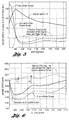
- Figure 3 shows the behaviour of the engine speed in a negative transient for the case where the friction losses were underestimated (the real losses are higher than estimated) by a constant offset of 10 Nm . If the friction losses are underestimated, then the engine speed converges to very low value, causing a risk for engine stall. Errors in the estimation of the friction losses thus can lead directly to deterioration of drivability performance.
- the friction torque is presented as a look-up table with two inputs ⁇ and T ind .
- the sites or nodes of the look-up table should be updated so that the absolute values of the error e ( t ) is reduced after each start event.
- the control aim can be presented as follows:
- the system as described, can be seen as a model reference adaptive system driven by the engine start events.
- Estimation of friction torque can be solved in two steps.
- the deviation from the engine friction torque which is pre-calibrated, is calculated for each start event by a comparison of j ⁇ and T brake - T acs at a certain interval.
- the number of the actual values of the engine friction torque is computed.
- the number of the actual values of the engine friction torque as a function of speed and indicated torque is the input to the second step.
- the sites or nodes of the friction torque look-up table are adapted so that the deviation between J ⁇ and T brake - T acs is reduced for the next start event.
- the engine friction torque can be presented as a sum of two components, T fc + ⁇ T f , where T fc is the engine torque calibrated in the rig and ⁇ T f is the deviation from the calibrated torque.
- the points on the time scale t p when ⁇ T f is evaluated should be well separated from each other, providing information about ⁇ T f for different values of the engine speed and indicated torque. From two to four measured points can be obtained during a negative transient. One point is obtained at idle.
- a spline interpolation method is based on on-line least-squares polynomial fitting over a moving-in-time window of a certain size.
- the advantage of this method over the backward difference method is its good transient behaviour.
- the idea for the spline interpolation method is to fit a polynomial of a certain order as a function of time in the least-squares sense and to take the derivatives analytically. Since the sites of the friction look-up table are adapted after the engine start events, a post-processing of the signals is allowed; i.e., the signals are memorized and processed offline.
- the spline interpolation method gives an accurate estimate of the derivative of the engine speed during post-processing since the derivative of the engine speed is computed in the middle of a moving window. This technique improves essentially the quality of the engine speed derivative signal. Other signals in (4) should also be delayed.
- Figure 4 shows the behaviour of engine speed, together with its derivative and engine brake torque during a start.
- the derivative of the engine speed is computed by using the spline interpolation method with a window size of 250 steps (each step is 4ms). The derivative was computed in the middle of the moving window.
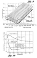
- Figure 5 shows the difference between J ⁇ (dashed line) and engine brake torque (dashdot line). The difference is plotted with a dotted line. The points where ⁇ T f is calculated are shown with plus signs. The deviations from the calibrated friction losses ⁇ T f as a function of engine speed and indicated torque are the inputs for adaptation algorithms, to be described subsequently. As can be seen from Figure 6, the deviations ⁇ T f are estimated with some errors. For each deviation ⁇ T f , a weight, which indicates the consistency of the point, is assigned. As can be seen from the Figures 5 and 6, two points are available for adaptation of the friction losses. The third point for calculation ⁇ T f is available when the engine is idling.
- the deviation ⁇ T f at idle is averaged over a certain number of steps, providing a consistent estimate. Therefore, the weight for the deviation ⁇ T f at idle is chosen higher, since engine idle conditions provide a more consistent estimate of ⁇ T f than engine start conditions.
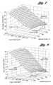
- Figure 7 shows a three dimensional plot of the friction torque with an overestimated offset of 10 Nm . Two points obtained at engine start and a third point obtained at engine idle are shown with plus signs. The point obtained at idle is shown with a round sign added.
- the adaptive problem statement is the following: It is necessary to design an adaptation algorithm for the sites or nodes of the look-up table by using three measured points of the actual friction torque.
- Figure 8 shows the relation between the actual engine friction torque (three dimensional manifold) and the estimated friction at engine start (two points plotted with plus signs) and the friction torque estimated at engine idle plotted with plus sign in a round sign.
- the values of the friction torque evaluated at engine start are located above the surface and below the surface, while a value of the engine torque estimated at engine idle is located precisely on the surface.
- the estimation of the engine friction torque at engine start provides less consistent estimates than estimates of the friction torque at engine idle. Therefore, the measurements of the friction torque at idle and at start should be treated differently by assigning different weights in the adaptation algorithms.
- engine friction torque is plotted as a function of the engine speed and indicated engine torque.
- the friction torque is overestimated by 10[ Nm ].
- Two points representing the estimated friction torque from the start are plotted with plus signs.
- the point that represents the estimated friction torque at idle is plotted with round and plus signs.
- the algorithm of the adaptation of the sites or nodes of two dimensional tables can be divided into three steps.
- the look-up table is approximated by a polynomial of two independent variables in the least-squares sense.
- a recursive procedure is designed for adaptation of the coefficients of the polynomial when new data are added.
- the approximation error is cancelled. Namely, the differences between the polynomial approximation of the original table and polynomial after adaptation are evaluated at every site or node and added to original look-up table. This allows a cancellation of the approximation error and usage of low order polynomials, which are more robust with respect to measurement errors.
- Only the sites or nodes of the look-up table are adapted as a result of the application of the algorithm described above. The values of the friction torque between the sites or nodes are obtained by linear interpolation.
- Adaptation algorithms described above were applied to adaptation of two dimensional look-up tables for purposes of illustration only.
- the algorithms can be generalized, however, for a multi-dimensional case where the dimension of the look-up table is higher than two. This can be done without departing from the scope of the invention.
- Figure 10 shows that friction losses have been correctly adapted.
- Engine speed at start is plotted with a solid line.
- the values of the engine speed are divided by ten.
- Engine brake torque is plotted with a dashdot line.
- the derivative of the engine speed multiplied by the inertia moment J ⁇ is plotted with a dashed line.
- An opportunity for obtaining an accurate engine friction torque estimation is the period following engine start.
- the engine speed increases to a relatively high level compared with the idle speed, and then slowly decreases, converging to the desired idle speed.
- Newton's law for rotational dynamics can be used as a reference model.
- the difference between the derivative of the engine speed multiplied by the inertia moment and the engine brake torque then can be seen as a deviation from the reference model. If the friction losses are correctly estimated, the deviation from the reference model is close to zero at the interval of interest.
- This reference model should be valid during long term engine operation. Any deviation from the reference model at the interval of interest is assumed to be related to the friction losses, since the aging of the engine components first of all affects the friction losses. If a deviation from the reference model is detected, then the friction look-up table is updated so that the deviation is minimized.
- the present invention is a model reference adaptive method driven by engine start events.
- the algorithm used in the present invention can be divided into two parts. The first part is the estimation of the friction losses at engine start and at idle, and the second part is the adaptation of a friction torque look-up table.
- the total engine operating region is divided into several parts and new values are stored for every operating region, thereby forming a new look-up table.
- Linear interpolation is used for interpolating the values of the table between the regions.
- the engine friction torque look-up table is adapted by using new data at low speeds and indicated torques only. If the values of the friction torque are not renewed in other regions, then there could be a big difference between the values of the friction torque in the segment of low speeds and indicated torques and the values of the friction torque in the neighbouring segments. The friction torque during a transient from low speeds and indicated torques to higher speeds and indicated torques then would change significantly. This would deteriorate performance of the engine control system, which is based on a torque model.
- the present invention includes the use of algorithms for the adaptation of the look-up tables that allow a prediction of the values of the friction torque, even for the operating regions with sparse new data representation.
- the present invention uses a look-up table of the friction losses as a function of engine speed and indicated torque, which is presented in the form of a manifold in three dimensional space.
- the shape of the manifold results from a physical dependence of friction torque as a function of speed and indicated torque (the friction increases with speed and indicated torque). If new data is available in a certain operating region only, then a part of each of the manifold coefficients is adapted (for example, the offset and the gradient in the engine speed direction). This determines the shape of the manifold and a prediction of the values in the regions without new data to be maintained.
- the invention uses a polynomial approximation of the manifold in the least-squares sense. New data are added with a certain weighting factor to the old data, and a part of the coefficients of the polynomial is updated or adapted in the least-squares sense. Adaptation of the part of the coefficients of the polynomial allows using 'a priori' information present in the non-adaptive part.
- the friction torque can be estimated for a wide range of speeds and loads, even with few measured points, by taking into account physical dependencies. These are present in the shape of the manifold.
Landscapes
- Engineering & Computer Science (AREA)
- Chemical & Material Sciences (AREA)
- Combustion & Propulsion (AREA)
- Mechanical Engineering (AREA)
- General Engineering & Computer Science (AREA)
- Combined Controls Of Internal Combustion Engines (AREA)
Applications Claiming Priority (1)
| Application Number | Priority Date | Filing Date | Title |
|---|---|---|---|
| US11/252,286 US7054738B1 (en) | 2005-10-17 | 2005-10-17 | Method for estimating engine friction torque |
Publications (3)
| Publication Number | Publication Date |
|---|---|
| EP1775451A2 true EP1775451A2 (de) | 2007-04-18 |
| EP1775451A3 EP1775451A3 (de) | 2008-09-10 |
| EP1775451B1 EP1775451B1 (de) | 2010-10-06 |
Family
ID=36462753
Family Applications (1)
| Application Number | Title | Priority Date | Filing Date |
|---|---|---|---|
| EP06122087A Ceased EP1775451B1 (de) | 2005-10-17 | 2006-10-11 | Verfahrer zur Bestimmung eines Reibungsdrehmoment |
Country Status (3)
| Country | Link |
|---|---|
| US (1) | US7054738B1 (de) |
| EP (1) | EP1775451B1 (de) |
| DE (1) | DE602006017316D1 (de) |
Cited By (1)
| Publication number | Priority date | Publication date | Assignee | Title |
|---|---|---|---|---|
| KR20130132315A (ko) * | 2012-05-25 | 2013-12-04 | 로베르트 보쉬 게엠베하 | 내연기관의 손실 토크의 적응을 위한 방법 및 장치 |
Families Citing this family (18)
| Publication number | Priority date | Publication date | Assignee | Title |
|---|---|---|---|---|
| JP2005090353A (ja) * | 2003-09-17 | 2005-04-07 | Hino Motors Ltd | 過渡エンジン性能適合化方法およびシステム |
| JP4345747B2 (ja) * | 2006-01-30 | 2009-10-14 | トヨタ自動車株式会社 | 内燃機関の制御装置 |
| SE529742C2 (sv) * | 2006-04-07 | 2007-11-13 | Scania Cv Abp | Förfarande för justering av en uppslagstabell och ett system för styrning av en injektor hos en cylinder i en förbränningsmotor |
| US7324888B1 (en) | 2006-10-02 | 2008-01-29 | Ford Global Technologies, Llc | Computationally efficient data-driven algorithms for engine friction torque estimation |
| US7650220B2 (en) * | 2007-11-26 | 2010-01-19 | Detroit Diesel Corporation | Method for anti-alias dual processing loop data acquisition in an internal combustion engine |
| JP5124398B2 (ja) * | 2008-09-01 | 2013-01-23 | ヤマハ発動機株式会社 | トルク推定システムおよび車両 |
| FR2943024B1 (fr) * | 2009-03-10 | 2012-07-13 | Peugeot Citroen Automobiles Sa | Procede de determination du couple inertiel et du couple de perte moteur |
| JP5461049B2 (ja) * | 2009-04-07 | 2014-04-02 | 株式会社デンソー | エンジン制御装置 |
| US8437927B2 (en) * | 2009-09-01 | 2013-05-07 | GM Global Technology Operations LLC | System and method for determining engine friction |
| US8602001B2 (en) * | 2010-09-17 | 2013-12-10 | GM Global Technology Operations LLC | Torque limiting engine lubrication protection system |
| CN105026909B (zh) * | 2012-12-27 | 2017-03-22 | 冷王公司 | 评估原动机的运行性能的系统和方法 |
| US9914450B2 (en) * | 2015-04-09 | 2018-03-13 | Hyundai Motor Company | Apparatus and method for learning engine friction torque of hybrid vehicle |
| US10108197B2 (en) * | 2015-12-08 | 2018-10-23 | Ford Global Technologies, Llc | Deceleration determination of a vehicle |
| US10202144B2 (en) | 2015-12-08 | 2019-02-12 | Ford Global Technologies, Llc | Vehicle curvature determination |
| US11313302B1 (en) | 2021-07-06 | 2022-04-26 | Hyundai Motor Company | Engine idle speed optimization |
| US12416272B2 (en) * | 2021-09-16 | 2025-09-16 | Polaris Industries Inc. | Systems and methods for engine start |
| CN114623009B (zh) * | 2022-03-16 | 2023-05-23 | 东风汽车集团股份有限公司 | 一种发动机扭矩调控方法、装置、电子设备和存储介质 |
| CN116118708B (zh) * | 2023-01-18 | 2026-01-13 | 赛力斯汽车有限公司 | 一种增程器的启动方法 |
Family Cites Families (12)
| Publication number | Priority date | Publication date | Assignee | Title |
|---|---|---|---|---|
| US5651341A (en) * | 1995-02-08 | 1997-07-29 | Mazda Motor Corporation | Control system for dynamically operative apparatuses |
| GB2329713A (en) * | 1997-09-30 | 1999-03-31 | Ford Global Tech Inc | IC engine net torque calculator |
| US6188951B1 (en) | 1999-09-23 | 2001-02-13 | Daimlerchrysler Corporation | Engine friction characterization |
| US6176218B1 (en) | 1999-09-23 | 2001-01-23 | Daimlerchrysler Corporation | Stabilizing function for torque based idle control |
| DE10019400A1 (de) | 2000-04-19 | 2001-10-25 | Bosch Gmbh Robert | Verfahren zur Anpassung eines Adaptionskennfelds einer adaptiven Brennkraftmaschinen-Klopfregelung und Verfahren zur adaptiven Klopfregelung einer Brennkraftmaschine |
| DE10043689A1 (de) * | 2000-09-04 | 2002-03-14 | Bosch Gmbh Robert | Verfahren zur Verlustmomentenadaption bei einer Brennkraftmaschine |
| US6553958B1 (en) | 2001-04-11 | 2003-04-29 | Ford Global Technologies, Inc. | Adaptive torque model for internal combustion engine |
| KR100448363B1 (ko) | 2001-11-28 | 2004-09-10 | 현대자동차주식회사 | 자동 변속기의 엔진 토크 제어방법 |
| US6655353B1 (en) * | 2002-05-17 | 2003-12-02 | General Motors Corporation | Cylinder deactivation engine control system with torque matching |
| US6990401B2 (en) | 2002-10-04 | 2006-01-24 | Daimlerchrysler Ag | Predictive speed control for a motor vehicle |
| GB0227672D0 (en) * | 2002-11-27 | 2003-01-08 | Ricardo Consulting Eng | Improved engine management |
| DE10306418A1 (de) * | 2003-02-15 | 2004-08-26 | Deere & Company, Moline | Antriebsanordnung für ein Förderaggregat |
-
2005
- 2005-10-17 US US11/252,286 patent/US7054738B1/en not_active Expired - Lifetime
-
2006
- 2006-10-11 EP EP06122087A patent/EP1775451B1/de not_active Ceased
- 2006-10-11 DE DE602006017316T patent/DE602006017316D1/de active Active
Cited By (1)
| Publication number | Priority date | Publication date | Assignee | Title |
|---|---|---|---|---|
| KR20130132315A (ko) * | 2012-05-25 | 2013-12-04 | 로베르트 보쉬 게엠베하 | 내연기관의 손실 토크의 적응을 위한 방법 및 장치 |
Also Published As
| Publication number | Publication date |
|---|---|
| EP1775451B1 (de) | 2010-10-06 |
| DE602006017316D1 (de) | 2010-11-18 |
| EP1775451A3 (de) | 2008-09-10 |
| US7054738B1 (en) | 2006-05-30 |
Similar Documents
| Publication | Publication Date | Title |
|---|---|---|
| EP1775451B1 (de) | Verfahrer zur Bestimmung eines Reibungsdrehmoment | |
| US8010272B2 (en) | Control device for internal combustion engine | |
| KR100348337B1 (ko) | 자동차프로세스의개방루프/폐쇄루프제어방법 | |
| CN100422529C (zh) | 用于控制驱动单元的方法和装置 | |
| US6065449A (en) | Fuel injection control device for an internal combustion engine | |
| JPH07122412B2 (ja) | 内燃機関駆動車両の加速制御装置 | |
| DE102007047763A1 (de) | Verfahren zum Anpassen eines Drehmomentmodells für eine verbesserte Erkennung des Nulldrehmoments | |
| EP4438385A1 (de) | Fahrzeug und aktives dämpfungssteuerungsverfahren dafür sowie fahrzeugsteuereinheit | |
| US5382206A (en) | Method of and system for controlling the speed of a motor vehicle based on an adjustable control characteristic so that the speed of the vehicle follows a target speed | |
| US7324888B1 (en) | Computationally efficient data-driven algorithms for engine friction torque estimation | |
| Stotsky | Adaptive estimation of the engine friction torque | |
| US20070179016A1 (en) | Engine control apparatus | |
| JPH0816215A (ja) | 機器の制御装置および制御方法 | |
| WO2007085968A2 (en) | Engine torque apparatus and method | |
| JP4048719B2 (ja) | エンジンの制御装置 | |
| Stotsky | Engine Friction Estimation at Start | |
| JP4104425B2 (ja) | 内燃機関の吸気管圧力予測方法および装置 | |
| KR20180100764A (ko) | 엔진클러치 마찰계수 학습 방법 | |
| JP4076204B2 (ja) | エンジンのスロットル弁の制御方法および制御装置 | |
| KR20190051830A (ko) | 부동 시간이 보상되는 연소 엔진의 회전수를 제어하기 위한 방법 | |
| JP2605693B2 (ja) | 車両用スロツトルバルブの制御装置 | |
| US12447946B1 (en) | Torque control modeling for torque control of hybrid electric powertrains | |
| JP3358624B2 (ja) | 内燃機関の燃料噴射制御装置 | |
| JP3035427B2 (ja) | アイドル回転数制御方法 | |
| US20250214446A1 (en) | Control system for electric vehicle |
Legal Events
| Date | Code | Title | Description |
|---|---|---|---|
| PUAI | Public reference made under article 153(3) epc to a published international application that has entered the european phase |
Free format text: ORIGINAL CODE: 0009012 |
|
| AK | Designated contracting states |
Kind code of ref document: A2 Designated state(s): AT BE BG CH CY CZ DE DK EE ES FI FR GB GR HU IE IS IT LI LT LU LV MC NL PL PT RO SE SI SK TR |
|
| AX | Request for extension of the european patent |
Extension state: AL BA HR MK YU |
|
| PUAL | Search report despatched |
Free format text: ORIGINAL CODE: 0009013 |
|
| AK | Designated contracting states |
Kind code of ref document: A3 Designated state(s): AT BE BG CH CY CZ DE DK EE ES FI FR GB GR HU IE IS IT LI LT LU LV MC NL PL PT RO SE SI SK TR |
|
| AX | Request for extension of the european patent |
Extension state: AL BA HR MK RS |
|
| 17P | Request for examination filed |
Effective date: 20090212 |
|
| AKX | Designation fees paid |
Designated state(s): DE GB SE |
|
| GRAP | Despatch of communication of intention to grant a patent |
Free format text: ORIGINAL CODE: EPIDOSNIGR1 |
|
| GRAS | Grant fee paid |
Free format text: ORIGINAL CODE: EPIDOSNIGR3 |
|
| GRAA | (expected) grant |
Free format text: ORIGINAL CODE: 0009210 |
|
| AK | Designated contracting states |
Kind code of ref document: B1 Designated state(s): DE GB SE |
|
| REG | Reference to a national code |
Ref country code: GB Ref legal event code: FG4D |
|
| REF | Corresponds to: |
Ref document number: 602006017316 Country of ref document: DE Date of ref document: 20101118 Kind code of ref document: P |
|
| REG | Reference to a national code |
Ref country code: SE Ref legal event code: TRGR |
|
| PLBE | No opposition filed within time limit |
Free format text: ORIGINAL CODE: 0009261 |
|
| STAA | Information on the status of an ep patent application or granted ep patent |
Free format text: STATUS: NO OPPOSITION FILED WITHIN TIME LIMIT |
|
| 26N | No opposition filed |
Effective date: 20110707 |
|
| REG | Reference to a national code |
Ref country code: DE Ref legal event code: R097 Ref document number: 602006017316 Country of ref document: DE Effective date: 20110707 |
|
| REG | Reference to a national code |
Ref country code: DE Ref legal event code: R082 Ref document number: 602006017316 Country of ref document: DE Representative=s name: PATENTANWALTSKANZLEI MEYER, DE |
|
| REG | Reference to a national code |
Ref country code: GB Ref legal event code: 732E Free format text: REGISTERED BETWEEN 20140109 AND 20140115 |
|
| REG | Reference to a national code |
Ref country code: DE Ref legal event code: R082 Ref document number: 602006017316 Country of ref document: DE Representative=s name: PATENTANWALTSKANZLEI MEYER, DE Effective date: 20140113 Ref country code: DE Ref legal event code: R081 Ref document number: 602006017316 Country of ref document: DE Owner name: VOLVO CAR CORPORATION, SE Free format text: FORMER OWNER: FORD GLOBAL TECHNOLOGIES, LLC, DEARBORN, US Effective date: 20140113 Ref country code: DE Ref legal event code: R081 Ref document number: 602006017316 Country of ref document: DE Owner name: VOLVO CAR CORPORATION, SE Free format text: FORMER OWNER: FORD GLOBAL TECHNOLOGIES, LLC, DEARBORN, MICH., US Effective date: 20140113 |
|
| PGFP | Annual fee paid to national office [announced via postgrant information from national office to epo] |
Ref country code: GB Payment date: 20151023 Year of fee payment: 10 |
|
| PGFP | Annual fee paid to national office [announced via postgrant information from national office to epo] |
Ref country code: SE Payment date: 20151027 Year of fee payment: 10 |
|
| GBPC | Gb: european patent ceased through non-payment of renewal fee |
Effective date: 20161011 |
|
| PG25 | Lapsed in a contracting state [announced via postgrant information from national office to epo] |
Ref country code: GB Free format text: LAPSE BECAUSE OF NON-PAYMENT OF DUE FEES Effective date: 20161011 |
|
| PG25 | Lapsed in a contracting state [announced via postgrant information from national office to epo] |
Ref country code: SE Free format text: LAPSE BECAUSE OF NON-PAYMENT OF DUE FEES Effective date: 20161012 |
|
| PGFP | Annual fee paid to national office [announced via postgrant information from national office to epo] |
Ref country code: DE Payment date: 20220920 Year of fee payment: 17 |
|
| REG | Reference to a national code |
Ref country code: DE Ref legal event code: R119 Ref document number: 602006017316 Country of ref document: DE |
|
| PG25 | Lapsed in a contracting state [announced via postgrant information from national office to epo] |
Ref country code: DE Free format text: LAPSE BECAUSE OF NON-PAYMENT OF DUE FEES Effective date: 20240501 |