EP1771662B1 - Cassette de pompe peristaltique comprenant un organe de reglage du pincement du tube - Google Patents
Cassette de pompe peristaltique comprenant un organe de reglage du pincement du tube Download PDFInfo
- Publication number
- EP1771662B1 EP1771662B1 EP05778710A EP05778710A EP1771662B1 EP 1771662 B1 EP1771662 B1 EP 1771662B1 EP 05778710 A EP05778710 A EP 05778710A EP 05778710 A EP05778710 A EP 05778710A EP 1771662 B1 EP1771662 B1 EP 1771662B1
- Authority
- EP
- European Patent Office
- Prior art keywords
- cassette
- cam
- unit
- tube
- peristaltic pump
- Prior art date
- Legal status (The legal status is an assumption and is not a legal conclusion. Google has not performed a legal analysis and makes no representation as to the accuracy of the status listed.)
- Expired - Lifetime
Links
Images
Classifications
-
- F—MECHANICAL ENGINEERING; LIGHTING; HEATING; WEAPONS; BLASTING
- F04—POSITIVE - DISPLACEMENT MACHINES FOR LIQUIDS; PUMPS FOR LIQUIDS OR ELASTIC FLUIDS
- F04C—ROTARY-PISTON, OR OSCILLATING-PISTON, POSITIVE-DISPLACEMENT MACHINES FOR LIQUIDS; ROTARY-PISTON, OR OSCILLATING-PISTON, POSITIVE-DISPLACEMENT PUMPS
- F04C5/00—Rotary-piston machines or pumps with the working-chamber walls at least partly resiliently deformable
-
- F—MECHANICAL ENGINEERING; LIGHTING; HEATING; WEAPONS; BLASTING
- F04—POSITIVE - DISPLACEMENT MACHINES FOR LIQUIDS; PUMPS FOR LIQUIDS OR ELASTIC FLUIDS
- F04B—POSITIVE-DISPLACEMENT MACHINES FOR LIQUIDS; PUMPS
- F04B43/00—Machines, pumps, or pumping installations having flexible working members
- F04B43/12—Machines, pumps, or pumping installations having flexible working members having peristaltic action
- F04B43/1253—Machines, pumps, or pumping installations having flexible working members having peristaltic action by using two or more rollers as squeezing elements, the rollers moving on an arc of a circle during squeezing
- F04B43/1284—Means for pushing the backing-plate against the tubular flexible member
-
- F—MECHANICAL ENGINEERING; LIGHTING; HEATING; WEAPONS; BLASTING
- F04—POSITIVE - DISPLACEMENT MACHINES FOR LIQUIDS; PUMPS FOR LIQUIDS OR ELASTIC FLUIDS
- F04B—POSITIVE-DISPLACEMENT MACHINES FOR LIQUIDS; PUMPS
- F04B43/00—Machines, pumps, or pumping installations having flexible working members
- F04B43/12—Machines, pumps, or pumping installations having flexible working members having peristaltic action
- F04B43/1253—Machines, pumps, or pumping installations having flexible working members having peristaltic action by using two or more rollers as squeezing elements, the rollers moving on an arc of a circle during squeezing
Definitions
- the invention relates to peristaltic pumps.
- Peristaltic pumps have been known for many years and are widely used especially in medicine and research laboratories. They have the characteristic of causing the displacement of a liquid through a tube without a piece of the pump comes into contact with the liquid. It therefore becomes possible to pump liquids sensitive to external contamination such as blood.
- the pump comprises rotating rollers that move by locally crushing the flexible tube, causing the liquid to move within the flexible tube.
- the pump of the aforementioned document comprises removable cassettes each comprising a tube and a movable cam sliding which urges the tube against the rollers to ensure good contact thereof with the tube.
- the pump comprises means for adjusting the intensity of the clamping exerted by the cam on the tube.
- These means comprise two sliders movable inside the cassette so as to solicit the cam by corner effect.
- Each of the sliders is engaged with a threaded portion of a rod whose rotation can be controlled from the outside by a button.
- a disadvantage of this arrangement is that the adjustment of the clamping means is relatively long when it is necessary to change the clamping intensity over a large amplitude.
- An object of the invention is to facilitate and in particular to accelerate the use of the clamping means.
- a peristaltic pump cassette comprising the technical features defined in claim 1.
- the organ can be moved easily and quickly, including a large amplitude.
- a peristaltic pump comprising a technical features defined in claim 9.
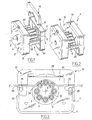
- FIGS. 1 to 5 illustrate a peristaltic pump head with a cassette according to a preferred embodiment of the invention.
- the head 2 comprises a housing 4 having a main axis of symmetry 6.
- the head comprises a set of rollers 8 which are in this case eight in number.
- the rollers are arranged symmetrically about the axis 6.
- the rollers are rotatably mounted on a central support 10.
- Each of the rollers has in this case a cylindrical shape, the axis of each roll being parallel to the main axis 6.
- the pump comprises means not illustrated and known in themselves for rotating the support 10 about the axis 6.
- the casing 4 comprises two main front walls 12 and rear 14 defining between them a housing 16 for receiving several cassettes 18 such as that shown in Figure 1.
- the cassettes can be received in the housing 16 as shown in Figure 2.
- the walls 12 and 14 are connected to one another by two rods 20 extending parallel to the axis 6 and serving as support and locking means to each of the cassettes 18, in cooperation therewith.
- Each cassette has a substantially flat shape and thus extends in a plane perpendicular to the axis 6.
- each cassette comprises a body 22 and a flexible tube 24 removably mounted in the body 22 by passing in particular through notches 25 of the latter.
- the body is substantially U-shaped in shape and comprises an elongated apex forming a cross-member 26 having two ends from which two arms 28 descend. notches 25 are formed in the vicinity of the lower ends of the arms 28. These same ends constitute the fastening and locking means of the cassette 18 to the head 2.
- a cavity 30 is formed facing the crosspiece 26, between the arms 28.
- the cassette 18 comprises a cam 32 received in the cavity 30.
- the cam 32 has a substantially flat rectangular shape with a recess in the shape of a hump in its lower face 34 intended to face the rollers 8.
- the tube 24 abuts against this edge 34 of the cam.
- the portion of the tube bearing against this edge is that which extends between the portions of the tube housed in the notches 25.
- the cassette has two walls 36 front and rear each extending from one to the other of the arms 28. to partially cover each face of the cam 32.
- the cassette 18 includes a leaf spring 38.
- a medial portion of the spring extends in the vicinity of the central portion of the cross member 26
- the end portions of the spring are fixed to the cam 32 by means of hooks 40 extending for this purpose projecting from an upper edge 41 of the cam.
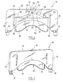
- the flexible tube was removed for clarity in Figures 4 and 5.
- Days 42 formed in the walls 36 show on each side of the cassette the ends of the spring 38.
- the cassette 18 comprises a slider 50 in the general shape of a rectangular parallelepiped.
- the slide 50 is in contact by its lower face with the upper face of the central zone of the spring 38. Preferably, it is fixed to this face.
- the slide is slidably mounted in two grooves 52 formed respectively in the front and rear faces of the crosspiece 26 and extending facing one another. The middle portion of the slider is not housed in the grooves. The grooves extend in the vertical direction to allow the slide to move vertically.
- the median zone of the crosspiece 26 comprises facing grooves 52 a recess 54 receiving a control member which is here constituted by a slider 56.
- the recess 54 is extended upwards by a chimney extending to the upper face of the cross member 26 forming therein an orifice through which extends a finger 60 of the protruding slider from the upper side.
- the cavity 54 On either side of the base of the chimney, the cavity 54 has an upper face 55 oriented downwards and having a notch constituted by a succession of teeth.
- the slider 56 has an upper face 57 on either side of the finger 60, provided with a complementary shaped detent. In this way, this face 57 can engage with the upper face 55 of the crosspiece 26 to immobilize the slider 60 by complementarity of shape, that is to say by engaging the notches of the slider with the notches from the crossing 26.
- the slider has a lower face 62 inclined to give the cursor a configuration and a corner function. This face comes into contact with the upper face of the slider 50 in order to urge it downwards, that is to say towards the tube 24.
- the spring 38 therefore has the function of tending to move the slider 56 and the cam 32 away from each other by urging the slider upwards and the cam downwards, respectively.
- the cam it is blocked down by the flexible tube.
- the slider 56 is resting on the slider 50, which presses the spring 38, which urges the cam 32 downwards, which in turn allows the tube to be urged towards the rollers 8.
- the slider 56 makes it possible to adjust the clamping force of the cam on the tube. At rest, the slider 56 is immobilized thanks to the notched connection by complementarity of shape with the crossbar 26. To modify the intensity of the clamping of the tube exerted by the cam, a downward pressure is exerted on the finger 60, which has the effect of disengaging the connection between the upper face of the slider and the upper face of the crossbar 26. In other words, the form of complementarity connection is interrupted. The slider can thus be operated to the left or to the right by holding it by the finger 60.
- the tightening will be less intense if you move the cursor to the right and will be more intense if you move the cursor to the left.
- just release the slider which, biased by the spring, recovers in the desired position with the upper face of the crossbar 26.
- This system makes it possible to adjust the clamping force of the tube 24, for example as a function of the diameter thereof, in order to optimize the flow-pressure torque as well as the screw life of the tubes. It is also possible by this means to take into account certain characteristics of the liquid carried in the tube.
- the displacement of the slider makes it possible to vary the crushing of the spring, and thus by interaction the gripping force of the tube via the cam. Maintaining the cursor in the rest position is ensured by the notches operating by complementarity of form. Thanks to the direct movement of the cursor, the intensity of the wedge clamping can be varied quickly and easily.
- Marks may be indicated on the upper face of the cassette to mark different positions of the cursor corresponding to predetermined clamping intensities. It will thus be possible to provide a graduation for adjusting the clamping intensity. This graduation may be a function, for example, of the diameter of the tube used.
- the invention optimizes the nip for better performance and longer life of the tube.
- the invention facilitates the repeatability of the adjustment, that is to say the ability to reproduce at different times the same clamping intensity.
- the presence of the slider 60 or intermediate piece avoids the transmission of lateral forces between the slider and the cam.
- the form-complementary connection can be constituted by means other than a notch. It may be for example a wave shape.
- disengagement of the connection is by means other than a support on the cursor.
- the cassette may be without springs. Thus, it can be provided that the cursor comes directly in contact with the cam.
- the invention can be implemented in a peristaltic pump without a removable cassette.
- the adjustment member may be a rotary member, for example cooperating with a screw-nut connection.
- adjustment member may be provided to arrange the adjustment member so that it is accessible in the upper part of the cassette regardless of the disengageable nature of the link associated with this body.
Landscapes
- Engineering & Computer Science (AREA)
- Mechanical Engineering (AREA)
- General Engineering & Computer Science (AREA)
- Reciprocating Pumps (AREA)
- External Artificial Organs (AREA)
Priority Applications (1)
| Application Number | Priority Date | Filing Date | Title |
|---|---|---|---|
| PL05778710T PL1771662T3 (pl) | 2004-06-22 | 2005-06-17 | Kaseta pompy perystaltycznej zawierająca człon regulujący docisk rurki |
Applications Claiming Priority (2)
| Application Number | Priority Date | Filing Date | Title |
|---|---|---|---|
| FR0406764A FR2871857B1 (fr) | 2004-06-22 | 2004-06-22 | Cassette de pompe peristaltique comprenant un organe de reglage du pincement du tube |
| PCT/FR2005/001524 WO2006008376A1 (fr) | 2004-06-22 | 2005-06-17 | Cassette de pompe peristaltique comprenant un organe de reglage du pincement du tube |
Publications (2)
| Publication Number | Publication Date |
|---|---|
| EP1771662A1 EP1771662A1 (fr) | 2007-04-11 |
| EP1771662B1 true EP1771662B1 (fr) | 2008-02-06 |
Family
ID=34947371
Family Applications (1)
| Application Number | Title | Priority Date | Filing Date |
|---|---|---|---|
| EP05778710A Expired - Lifetime EP1771662B1 (fr) | 2004-06-22 | 2005-06-17 | Cassette de pompe peristaltique comprenant un organe de reglage du pincement du tube |
Country Status (15)
| Country | Link |
|---|---|
| US (1) | US20070217932A1 (enExample) |
| EP (1) | EP1771662B1 (enExample) |
| JP (1) | JP2008503688A (enExample) |
| KR (1) | KR20070033003A (enExample) |
| CN (1) | CN1973132A (enExample) |
| AT (1) | ATE385543T1 (enExample) |
| CA (1) | CA2571734A1 (enExample) |
| DE (1) | DE602005004665T2 (enExample) |
| DK (1) | DK1771662T3 (enExample) |
| ES (1) | ES2301046T3 (enExample) |
| FR (1) | FR2871857B1 (enExample) |
| PL (1) | PL1771662T3 (enExample) |
| RU (1) | RU2006144289A (enExample) |
| TW (1) | TW200606339A (enExample) |
| WO (1) | WO2006008376A1 (enExample) |
Families Citing this family (41)
| Publication number | Priority date | Publication date | Assignee | Title |
|---|---|---|---|---|
| AU2007230945B2 (en) | 2006-03-23 | 2013-05-02 | The Penn State Research Foundation | Heart assist device with expandable impeller pump |
| US8062008B2 (en) | 2007-09-27 | 2011-11-22 | Curlin Medical Inc. | Peristaltic pump and removable cassette therefor |
| US8083503B2 (en) | 2007-09-27 | 2011-12-27 | Curlin Medical Inc. | Peristaltic pump assembly and regulator therefor |
| US7934912B2 (en) | 2007-09-27 | 2011-05-03 | Curlin Medical Inc | Peristaltic pump assembly with cassette and mounting pin arrangement |
| US8272857B2 (en) * | 2008-02-22 | 2012-09-25 | Medtronic Xomed, Inc. | Method and system for loading of tubing into a pumping device |
| JP2010043600A (ja) * | 2008-08-12 | 2010-02-25 | Osada Res Inst Ltd | ローラポンプ |
| JP5298699B2 (ja) | 2008-08-20 | 2013-09-25 | セイコーエプソン株式会社 | 制御ユニット、チューブユニット、マイクロポンプ |
| JP5282508B2 (ja) | 2008-09-29 | 2013-09-04 | セイコーエプソン株式会社 | 制御ユニット、チューブユニット、マイクロポンプ |
| JP5195368B2 (ja) | 2008-12-05 | 2013-05-08 | セイコーエプソン株式会社 | チューブユニット、制御ユニット、マイクロポンプ |
| JP5569014B2 (ja) * | 2010-02-03 | 2014-08-13 | セイコーエプソン株式会社 | 流体輸送装置 |
| DE102010053903B4 (de) * | 2010-12-09 | 2016-03-31 | Fresenius Medical Care Deutschland Gmbh | Pumpenrotor |
| WO2012094641A2 (en) | 2011-01-06 | 2012-07-12 | Thoratec Corporation | Percutaneous heart pump |
| US9504784B2 (en) | 2011-09-15 | 2016-11-29 | Cole-Parmer Instrument Company Llc | Peristaltic pump with multiple independent channels |
| US8721517B2 (en) | 2012-05-14 | 2014-05-13 | Thoratec Corporation | Impeller for catheter pump |
| GB2504176A (en) | 2012-05-14 | 2014-01-22 | Thoratec Corp | Collapsible impeller for catheter pump |
| DE102013008159A1 (de) | 2012-05-14 | 2013-11-14 | Thoratec Corporation | Mantelsystem für Katheterpumpe |
| US9358329B2 (en) | 2012-07-03 | 2016-06-07 | Thoratec Corporation | Catheter pump |
| CA2791344C (en) * | 2012-09-26 | 2019-07-16 | Capmatic Ltee | Peristaltic pump |
| ES2891995T3 (es) * | 2012-11-14 | 2022-02-01 | Kpr Us Llc | Casete de bomba peristáltica |
| WO2014099178A1 (en) | 2012-12-21 | 2014-06-26 | Alcon Research, Ltd. | Cassette clamp mechanism |
| US11033728B2 (en) | 2013-03-13 | 2021-06-15 | Tc1 Llc | Fluid handling system |
| JP6530367B2 (ja) | 2013-03-13 | 2019-06-12 | ティーシーワン エルエルシー | 流体導出入システム |
| EP4190376A1 (en) | 2013-03-15 | 2023-06-07 | Tc1 Llc | Catheter pump assembly including a stator |
| US9308302B2 (en) | 2013-03-15 | 2016-04-12 | Thoratec Corporation | Catheter pump assembly including a stator |
| USD762850S1 (en) | 2013-04-23 | 2016-08-02 | Covidien Lp | Cassette |
| WO2015160943A1 (en) | 2014-04-15 | 2015-10-22 | Thoratec Corporation | Sensors for catheter pumps |
| US10583232B2 (en) | 2014-04-15 | 2020-03-10 | Tc1 Llc | Catheter pump with off-set motor position |
| WO2016028644A1 (en) | 2014-08-18 | 2016-02-25 | Thoratec Corporation | Guide features for percutaneous catheter pump |
| EP3247420B1 (en) | 2015-01-22 | 2019-10-02 | Tc1 Llc | Reduced rotational mass motor assembly for catheter pump |
| EP3804804A1 (en) | 2016-07-21 | 2021-04-14 | Tc1 Llc | Fluid seals for catheter pump motor assembly |
| EP3808402A1 (en) | 2016-07-21 | 2021-04-21 | Tc1 Llc | Gas-filled chamber for catheter pump motor assembly |
| AU201710910S (en) * | 2016-08-18 | 2017-03-01 | Brightwell Dispensers Ltd | Peristaltic pump |
| AU201710912S (en) * | 2016-08-18 | 2017-03-01 | Brightwell Dispensers Ltd | Peristaltic pump |
| AU201713507S (en) * | 2016-12-23 | 2017-06-23 | Brightwell Dispensers Ltd | Peristaltic pump |
| EP3467309B1 (en) * | 2017-10-06 | 2020-02-26 | The Automation Partnership (Cambridge) Limited | Device and methods for improving and evaluating stability of pumped protein solutions in bioprocessing systems |
| EP3483440B1 (en) | 2017-11-08 | 2020-05-27 | Oina VV AB | Peristaltic pump |
| KR102136683B1 (ko) | 2019-02-27 | 2020-07-22 | 박종환 | 식품가공용 고점도 액상체의 이송효율이 개선된 튜브연동펌프 |
| JP7528112B2 (ja) * | 2019-03-15 | 2024-08-05 | ネクステージ メディカル インコーポレイテッド | 蠕動ポンプ |
| EP3999751B1 (en) | 2019-07-15 | 2024-04-17 | The Timken Company | Two-piece composite tapered roller bearing outer ring with interference fit |
| GB2616273A (en) * | 2022-03-01 | 2023-09-06 | Aliva AS | Liquid distribution system |
| WO2025137212A1 (en) * | 2023-12-22 | 2025-06-26 | Beckman Coulter, Inc. | Peristaltic pump with spring loaded housing |
Family Cites Families (17)
| Publication number | Priority date | Publication date | Assignee | Title |
|---|---|---|---|---|
| GB421629A (en) * | 1934-01-15 | 1934-12-27 | Manoel Cordeiro Santiago | Improvements in pumps of the flexible tube type |
| US3140666A (en) * | 1962-06-11 | 1964-07-14 | American Instr Co Inc | Peristaltic pump |
| DE2148468A1 (de) * | 1970-10-08 | 1972-04-13 | Snam Progetti | Peristaltische Pumpe mit mehreren kontinuierlich einstellbaren Kanaelen |
| US3918854A (en) * | 1974-06-19 | 1975-11-11 | Alphamedics Mfg Corp | Peristaltic pump |
| US4189286A (en) * | 1977-03-15 | 1980-02-19 | Fibra-Sonics, Inc. | Peristaltic pump |
| US4673334A (en) * | 1984-05-25 | 1987-06-16 | Isco, Inc. | Peristaltic pump |
| DE8516825U1 (de) * | 1985-06-08 | 1985-12-12 | Ernst Schütt jun. Laboratoriums-Einrichtungen Ärzte- und Krankenhausbedarf Fabrikation und Vertrieb, 3400 Göttingen | Stell- und Andrückvorrichtung für eine Schlauchpumpe |
| US4813855A (en) * | 1987-06-26 | 1989-03-21 | Tek-Aids Inc. | Peristaltic pump |
| JPH0821418B2 (ja) * | 1987-06-29 | 1996-03-04 | 松下電器産業株式会社 | 鉛蓄電池 |
| US4886431A (en) * | 1988-04-29 | 1989-12-12 | Cole-Parmer Instrument Company | Peristaltic pump having independently adjustable cartridges |
| GB2241541B (en) * | 1989-08-28 | 1993-06-16 | Csir | Peristaltic pump |
| JPH0452578U (enExample) * | 1990-09-07 | 1992-05-06 | ||
| FR2677711B1 (fr) * | 1991-06-12 | 1993-10-08 | Smh Management Services Ag | Pompe peristaltique. |
| US5213483A (en) * | 1991-06-19 | 1993-05-25 | Strato Medical Corporation | Peristaltic infusion pump with removable cassette and mechanically keyed tube set |
| US5257917A (en) * | 1992-10-02 | 1993-11-02 | Cole-Parmer Instrument Company | Peristaltic pump having means for reducing flow pulsation |
| US5904668A (en) * | 1995-03-06 | 1999-05-18 | Sabratek Corporation | Cassette for an infusion pump |
| US6494693B1 (en) * | 2000-10-23 | 2002-12-17 | Cole-Parmer Instrument Company | Peristatic pump |
-
2004
- 2004-06-22 FR FR0406764A patent/FR2871857B1/fr not_active Expired - Fee Related
-
2005
- 2005-06-17 DE DE602005004665T patent/DE602005004665T2/de not_active Expired - Fee Related
- 2005-06-17 ES ES05778710T patent/ES2301046T3/es not_active Expired - Lifetime
- 2005-06-17 CN CNA2005800208193A patent/CN1973132A/zh active Pending
- 2005-06-17 EP EP05778710A patent/EP1771662B1/fr not_active Expired - Lifetime
- 2005-06-17 CA CA002571734A patent/CA2571734A1/en not_active Abandoned
- 2005-06-17 RU RU2006144289/06A patent/RU2006144289A/ru not_active Application Discontinuation
- 2005-06-17 DK DK05778710T patent/DK1771662T3/da active
- 2005-06-17 JP JP2007517351A patent/JP2008503688A/ja active Pending
- 2005-06-17 KR KR1020077001389A patent/KR20070033003A/ko not_active Withdrawn
- 2005-06-17 WO PCT/FR2005/001524 patent/WO2006008376A1/fr not_active Ceased
- 2005-06-17 PL PL05778710T patent/PL1771662T3/pl unknown
- 2005-06-17 AT AT05778710T patent/ATE385543T1/de not_active IP Right Cessation
- 2005-06-21 TW TW094120642A patent/TW200606339A/zh unknown
-
2006
- 2006-12-18 US US11/612,011 patent/US20070217932A1/en not_active Abandoned
Also Published As
| Publication number | Publication date |
|---|---|
| CA2571734A1 (en) | 2006-01-26 |
| CN1973132A (zh) | 2007-05-30 |
| EP1771662A1 (fr) | 2007-04-11 |
| FR2871857A1 (fr) | 2005-12-23 |
| TW200606339A (en) | 2006-02-16 |
| ES2301046T3 (es) | 2008-06-16 |
| JP2008503688A (ja) | 2008-02-07 |
| WO2006008376A1 (fr) | 2006-01-26 |
| KR20070033003A (ko) | 2007-03-23 |
| FR2871857B1 (fr) | 2008-09-12 |
| US20070217932A1 (en) | 2007-09-20 |
| PL1771662T3 (pl) | 2008-07-31 |
| RU2006144289A (ru) | 2008-07-27 |
| ATE385543T1 (de) | 2008-02-15 |
| DE602005004665D1 (de) | 2008-03-20 |
| DK1771662T3 (da) | 2008-05-26 |
| DE602005004665T2 (de) | 2009-02-05 |
Similar Documents
| Publication | Publication Date | Title |
|---|---|---|
| EP1771662B1 (fr) | Cassette de pompe peristaltique comprenant un organe de reglage du pincement du tube | |
| CA2493148C (fr) | Dispositif de prehension amovible et adaptable a differentes epaisseurs de recipient | |
| EP0146454A2 (fr) | Dispositif de fixation d'une chaussure sur une pédale de bicyclette | |
| EP0023278B1 (fr) | Dispositif d'entraînement d'un support en forme de bande perforée | |
| FR2824542A1 (fr) | Pince de prehension de recipients et procede de transport correspondant | |
| EP0669274B1 (fr) | Dispositif de taquage latéral d'éléments plats sur une table | |
| EP0134595A1 (fr) | Chaussure de ski | |
| FR2945763A3 (fr) | Dispositif de coupe de blocs avec effet de levier de came ameliore | |
| FR2718217A1 (fr) | Socle mobile de parasol, à roues escamotables et non visibles. | |
| EP1226978A1 (fr) | Mécanisme de fermeture pour classeur | |
| CH629106A5 (fr) | Fixation de securite pour ski. | |
| EP1364867A1 (fr) | Freins mécaniques à patins pour bicyclettes | |
| EP1025882B1 (fr) | Ensemble chaussure-fixation de ski de sécurité | |
| WO2003072373A1 (fr) | Cadre de dispositif a usage médical ou paramédical de support roulant d'une personne, a roulettes facilement démontables, et dispositif ainsi équipe | |
| EP2573298A1 (fr) | Support de plaque pour appareil destiné à la pose de plaques sur des murs ou plafonds | |
| EP3059826B1 (fr) | Dispositif de suspension pour suspendre un câble de diamètre prédéterminé à un support | |
| EP0314555B1 (fr) | Vanne d'échantillonnage à déplacement linéaire et son dispositif de fixation | |
| EP1005809A1 (fr) | Ensemble à déploiement latéral stable du genre bureau ou table | |
| EP4493446B1 (fr) | Ensemble de tige de selle | |
| EP0156663A1 (fr) | Dispositif empêchant un ski de glisser en arrière | |
| FR2809613A1 (fr) | Dispositif supportant le corps pour un lit | |
| CH684151A5 (fr) | Fermoir de bracelet. | |
| FR3139145A1 (fr) | Suppport de douche avec réglage coulissant sans effort | |
| FR2780431A1 (fr) | Dispositif de blocage et de maintien d'un mat de parasol | |
| EP0604246B1 (fr) | Plateau pour supporter une feuille de papier en vue de son introduction dans un appareil tel qu'un télécopieur |
Legal Events
| Date | Code | Title | Description |
|---|---|---|---|
| PUAI | Public reference made under article 153(3) epc to a published international application that has entered the european phase |
Free format text: ORIGINAL CODE: 0009012 |
|
| 17P | Request for examination filed |
Effective date: 20070115 |
|
| AK | Designated contracting states |
Kind code of ref document: A1 Designated state(s): AT BE BG CH CY CZ DE DK EE ES FI FR GB GR HU IE IS IT LI LT LU MC NL PL PT RO SE SI SK TR |
|
| 17Q | First examination report despatched |
Effective date: 20070426 |
|
| GRAP | Despatch of communication of intention to grant a patent |
Free format text: ORIGINAL CODE: EPIDOSNIGR1 |
|
| DAX | Request for extension of the european patent (deleted) | ||
| GRAS | Grant fee paid |
Free format text: ORIGINAL CODE: EPIDOSNIGR3 |
|
| GRAA | (expected) grant |
Free format text: ORIGINAL CODE: 0009210 |
|
| AK | Designated contracting states |
Kind code of ref document: B1 Designated state(s): AT BE BG CH CY CZ DE DK EE ES FI FR GB GR HU IE IS IT LI LT LU MC NL PL PT RO SE SI SK TR |
|
| REG | Reference to a national code |
Ref country code: GB Ref legal event code: FG4D Free format text: NOT ENGLISH |
|
| REG | Reference to a national code |
Ref country code: CH Ref legal event code: EP |
|
| REG | Reference to a national code |
Ref country code: IE Ref legal event code: FG4D Free format text: LANGUAGE OF EP DOCUMENT: FRENCH |
|
| REF | Corresponds to: |
Ref document number: 602005004665 Country of ref document: DE Date of ref document: 20080320 Kind code of ref document: P |
|
| GBT | Gb: translation of ep patent filed (gb section 77(6)(a)/1977) |
Effective date: 20080420 |
|
| REG | Reference to a national code |
Ref country code: SE Ref legal event code: TRGR |
|
| REG | Reference to a national code |
Ref country code: DK Ref legal event code: T3 |
|
| REG | Reference to a national code |
Ref country code: ES Ref legal event code: FG2A Ref document number: 2301046 Country of ref document: ES Kind code of ref document: T3 |
|
| PG25 | Lapsed in a contracting state [announced via postgrant information from national office to epo] |
Ref country code: IS Free format text: LAPSE BECAUSE OF FAILURE TO SUBMIT A TRANSLATION OF THE DESCRIPTION OR TO PAY THE FEE WITHIN THE PRESCRIBED TIME-LIMIT Effective date: 20080606 Ref country code: FI Free format text: LAPSE BECAUSE OF FAILURE TO SUBMIT A TRANSLATION OF THE DESCRIPTION OR TO PAY THE FEE WITHIN THE PRESCRIBED TIME-LIMIT Effective date: 20080206 |
|
| PGFP | Annual fee paid to national office [announced via postgrant information from national office to epo] |
Ref country code: DK Payment date: 20080610 Year of fee payment: 4 Ref country code: ES Payment date: 20080627 Year of fee payment: 4 |
|
| REG | Reference to a national code |
Ref country code: PL Ref legal event code: T3 |
|
| PG25 | Lapsed in a contracting state [announced via postgrant information from national office to epo] |
Ref country code: AT Free format text: LAPSE BECAUSE OF FAILURE TO SUBMIT A TRANSLATION OF THE DESCRIPTION OR TO PAY THE FEE WITHIN THE PRESCRIBED TIME-LIMIT Effective date: 20080206 |
|
| PG25 | Lapsed in a contracting state [announced via postgrant information from national office to epo] |
Ref country code: SI Free format text: LAPSE BECAUSE OF FAILURE TO SUBMIT A TRANSLATION OF THE DESCRIPTION OR TO PAY THE FEE WITHIN THE PRESCRIBED TIME-LIMIT Effective date: 20080206 |
|
| PG25 | Lapsed in a contracting state [announced via postgrant information from national office to epo] |
Ref country code: PT Free format text: LAPSE BECAUSE OF FAILURE TO SUBMIT A TRANSLATION OF THE DESCRIPTION OR TO PAY THE FEE WITHIN THE PRESCRIBED TIME-LIMIT Effective date: 20080707 Ref country code: SK Free format text: LAPSE BECAUSE OF FAILURE TO SUBMIT A TRANSLATION OF THE DESCRIPTION OR TO PAY THE FEE WITHIN THE PRESCRIBED TIME-LIMIT Effective date: 20080206 Ref country code: CZ Free format text: LAPSE BECAUSE OF FAILURE TO SUBMIT A TRANSLATION OF THE DESCRIPTION OR TO PAY THE FEE WITHIN THE PRESCRIBED TIME-LIMIT Effective date: 20080206 |
|
| PGFP | Annual fee paid to national office [announced via postgrant information from national office to epo] |
Ref country code: DE Payment date: 20080620 Year of fee payment: 4 Ref country code: IE Payment date: 20080619 Year of fee payment: 4 Ref country code: NL Payment date: 20080618 Year of fee payment: 4 Ref country code: SE Payment date: 20080612 Year of fee payment: 4 |
|
| PG25 | Lapsed in a contracting state [announced via postgrant information from national office to epo] |
Ref country code: RO Free format text: LAPSE BECAUSE OF FAILURE TO SUBMIT A TRANSLATION OF THE DESCRIPTION OR TO PAY THE FEE WITHIN THE PRESCRIBED TIME-LIMIT Effective date: 20080206 |
|
| PGFP | Annual fee paid to national office [announced via postgrant information from national office to epo] |
Ref country code: FR Payment date: 20080613 Year of fee payment: 4 |
|
| PLBE | No opposition filed within time limit |
Free format text: ORIGINAL CODE: 0009261 |
|
| STAA | Information on the status of an ep patent application or granted ep patent |
Free format text: STATUS: NO OPPOSITION FILED WITHIN TIME LIMIT |
|
| 26N | No opposition filed |
Effective date: 20081107 |
|
| PG25 | Lapsed in a contracting state [announced via postgrant information from national office to epo] |
Ref country code: LT Free format text: LAPSE BECAUSE OF FAILURE TO SUBMIT A TRANSLATION OF THE DESCRIPTION OR TO PAY THE FEE WITHIN THE PRESCRIBED TIME-LIMIT Effective date: 20080206 Ref country code: MC Free format text: LAPSE BECAUSE OF NON-PAYMENT OF DUE FEES Effective date: 20080630 |
|
| PGFP | Annual fee paid to national office [announced via postgrant information from national office to epo] |
Ref country code: BE Payment date: 20080728 Year of fee payment: 4 Ref country code: PL Payment date: 20081002 Year of fee payment: 4 |
|
| PG25 | Lapsed in a contracting state [announced via postgrant information from national office to epo] |
Ref country code: EE Free format text: LAPSE BECAUSE OF FAILURE TO SUBMIT A TRANSLATION OF THE DESCRIPTION OR TO PAY THE FEE WITHIN THE PRESCRIBED TIME-LIMIT Effective date: 20080206 Ref country code: BG Free format text: LAPSE BECAUSE OF FAILURE TO SUBMIT A TRANSLATION OF THE DESCRIPTION OR TO PAY THE FEE WITHIN THE PRESCRIBED TIME-LIMIT Effective date: 20080506 |
|
| PG25 | Lapsed in a contracting state [announced via postgrant information from national office to epo] |
Ref country code: CY Free format text: LAPSE BECAUSE OF FAILURE TO SUBMIT A TRANSLATION OF THE DESCRIPTION OR TO PAY THE FEE WITHIN THE PRESCRIBED TIME-LIMIT Effective date: 20080206 |
|
| BERE | Be: lapsed |
Owner name: GILSON SAS Effective date: 20090630 |
|
| REG | Reference to a national code |
Ref country code: CH Ref legal event code: PL |
|
| REG | Reference to a national code |
Ref country code: DK Ref legal event code: EBP |
|
| GBPC | Gb: european patent ceased through non-payment of renewal fee |
Effective date: 20090617 |
|
| NLV4 | Nl: lapsed or anulled due to non-payment of the annual fee |
Effective date: 20100101 |
|
| REG | Reference to a national code |
Ref country code: FR Ref legal event code: ST Effective date: 20100226 |
|
| PG25 | Lapsed in a contracting state [announced via postgrant information from national office to epo] |
Ref country code: LI Free format text: LAPSE BECAUSE OF NON-PAYMENT OF DUE FEES Effective date: 20090630 Ref country code: CH Free format text: LAPSE BECAUSE OF NON-PAYMENT OF DUE FEES Effective date: 20090630 Ref country code: FR Free format text: LAPSE BECAUSE OF NON-PAYMENT OF DUE FEES Effective date: 20090630 Ref country code: IE Free format text: LAPSE BECAUSE OF NON-PAYMENT OF DUE FEES Effective date: 20090617 |
|
| PG25 | Lapsed in a contracting state [announced via postgrant information from national office to epo] |
Ref country code: GB Free format text: LAPSE BECAUSE OF NON-PAYMENT OF DUE FEES Effective date: 20090617 |
|
| PG25 | Lapsed in a contracting state [announced via postgrant information from national office to epo] |
Ref country code: DE Free format text: LAPSE BECAUSE OF NON-PAYMENT OF DUE FEES Effective date: 20100101 Ref country code: BE Free format text: LAPSE BECAUSE OF NON-PAYMENT OF DUE FEES Effective date: 20090630 |
|
| PG25 | Lapsed in a contracting state [announced via postgrant information from national office to epo] |
Ref country code: NL Free format text: LAPSE BECAUSE OF NON-PAYMENT OF DUE FEES Effective date: 20100101 Ref country code: LU Free format text: LAPSE BECAUSE OF NON-PAYMENT OF DUE FEES Effective date: 20080617 Ref country code: HU Free format text: LAPSE BECAUSE OF FAILURE TO SUBMIT A TRANSLATION OF THE DESCRIPTION OR TO PAY THE FEE WITHIN THE PRESCRIBED TIME-LIMIT Effective date: 20080807 Ref country code: DK Free format text: LAPSE BECAUSE OF NON-PAYMENT OF DUE FEES Effective date: 20090630 |
|
| REG | Reference to a national code |
Ref country code: ES Ref legal event code: FD2A Effective date: 20090618 |
|
| PG25 | Lapsed in a contracting state [announced via postgrant information from national office to epo] |
Ref country code: TR Free format text: LAPSE BECAUSE OF FAILURE TO SUBMIT A TRANSLATION OF THE DESCRIPTION OR TO PAY THE FEE WITHIN THE PRESCRIBED TIME-LIMIT Effective date: 20080206 |
|
| PG25 | Lapsed in a contracting state [announced via postgrant information from national office to epo] |
Ref country code: GR Free format text: LAPSE BECAUSE OF FAILURE TO SUBMIT A TRANSLATION OF THE DESCRIPTION OR TO PAY THE FEE WITHIN THE PRESCRIBED TIME-LIMIT Effective date: 20080507 Ref country code: ES Free format text: LAPSE BECAUSE OF NON-PAYMENT OF DUE FEES Effective date: 20090618 |
|
| REG | Reference to a national code |
Ref country code: PL Ref legal event code: LAPE |
|
| PG25 | Lapsed in a contracting state [announced via postgrant information from national office to epo] |
Ref country code: SE Free format text: LAPSE BECAUSE OF NON-PAYMENT OF DUE FEES Effective date: 20090618 Ref country code: PL Free format text: LAPSE BECAUSE OF NON-PAYMENT OF DUE FEES Effective date: 20090617 |
|
| PGFP | Annual fee paid to national office [announced via postgrant information from national office to epo] |
Ref country code: IT Payment date: 20080630 Year of fee payment: 4 |