EP1770426B1 - Veränderbare Anordnung von mikroskopischen Löchern - Google Patents
Veränderbare Anordnung von mikroskopischen Löchern Download PDFInfo
- Publication number
- EP1770426B1 EP1770426B1 EP06026140A EP06026140A EP1770426B1 EP 1770426 B1 EP1770426 B1 EP 1770426B1 EP 06026140 A EP06026140 A EP 06026140A EP 06026140 A EP06026140 A EP 06026140A EP 1770426 B1 EP1770426 B1 EP 1770426B1
- Authority
- EP
- European Patent Office
- Prior art keywords
- plates
- holes
- microscopic
- configuration
- modifiable
- Prior art date
- Legal status (The legal status is an assumption and is not a legal conclusion. Google has not performed a legal analysis and makes no representation as to the accuracy of the status listed.)
- Expired - Lifetime
Links
Images


Classifications
-
- G—PHYSICS
- G02—OPTICS
- G02B—OPTICAL ELEMENTS, SYSTEMS OR APPARATUS
- G02B21/00—Microscopes
- G02B21/0004—Microscopes specially adapted for specific applications
- G02B21/002—Scanning microscopes
- G02B21/0024—Confocal scanning microscopes (CSOMs) or confocal "macroscopes"; Accessories which are not restricted to use with CSOMs, e.g. sample holders
- G02B21/0032—Optical details of illumination, e.g. light-sources, pinholes, beam splitters, slits, fibers
-
- G—PHYSICS
- G02—OPTICS
- G02B—OPTICAL ELEMENTS, SYSTEMS OR APPARATUS
- G02B21/00—Microscopes
- G02B21/0004—Microscopes specially adapted for specific applications
- G02B21/002—Scanning microscopes
- G02B21/0024—Confocal scanning microscopes (CSOMs) or confocal "macroscopes"; Accessories which are not restricted to use with CSOMs, e.g. sample holders
- G02B21/0036—Scanning details, e.g. scanning stages
- G02B21/004—Scanning details, e.g. scanning stages fixed arrays, e.g. switchable aperture arrays
-
- G—PHYSICS
- G02—OPTICS
- G02B—OPTICAL ELEMENTS, SYSTEMS OR APPARATUS
- G02B21/00—Microscopes
- G02B21/0004—Microscopes specially adapted for specific applications
- G02B21/002—Scanning microscopes
- G02B21/0024—Confocal scanning microscopes (CSOMs) or confocal "macroscopes"; Accessories which are not restricted to use with CSOMs, e.g. sample holders
- G02B21/0036—Scanning details, e.g. scanning stages
- G02B21/0048—Scanning details, e.g. scanning stages scanning mirrors, e.g. rotating or galvanomirrors, MEMS mirrors
-
- G—PHYSICS
- G02—OPTICS
- G02B—OPTICAL ELEMENTS, SYSTEMS OR APPARATUS
- G02B21/00—Microscopes
- G02B21/0004—Microscopes specially adapted for specific applications
- G02B21/002—Scanning microscopes
- G02B21/0024—Confocal scanning microscopes (CSOMs) or confocal "macroscopes"; Accessories which are not restricted to use with CSOMs, e.g. sample holders
- G02B21/0052—Optical details of the image generation
- G02B21/0068—Optical details of the image generation arrangements using polarisation
-
- G—PHYSICS
- G02—OPTICS
- G02B—OPTICAL ELEMENTS, SYSTEMS OR APPARATUS
- G02B21/00—Microscopes
- G02B21/0004—Microscopes specially adapted for specific applications
- G02B21/002—Scanning microscopes
- G02B21/0024—Confocal scanning microscopes (CSOMs) or confocal "macroscopes"; Accessories which are not restricted to use with CSOMs, e.g. sample holders
- G02B21/0052—Optical details of the image generation
- G02B21/0076—Optical details of the image generation arrangements using fluorescence or luminescence
-
- G—PHYSICS
- G02—OPTICS
- G02B—OPTICAL ELEMENTS, SYSTEMS OR APPARATUS
- G02B21/00—Microscopes
- G02B21/0004—Microscopes specially adapted for specific applications
- G02B21/002—Scanning microscopes
- G02B21/0024—Confocal scanning microscopes (CSOMs) or confocal "macroscopes"; Accessories which are not restricted to use with CSOMs, e.g. sample holders
- G02B21/008—Details of detection or image processing, including general computer control
- G02B21/0084—Details of detection or image processing, including general computer control time-scale detection, e.g. strobed, ultra-fast, heterodyne detection
-
- G—PHYSICS
- G02—OPTICS
- G02B—OPTICAL ELEMENTS, SYSTEMS OR APPARATUS
- G02B5/00—Optical elements other than lenses
- G02B5/005—Diaphragms
Definitions
- the invention relates to a microscopic hole or a set of microscopic holes (in English "pinhole"), the number of these holes and / or their size can be easily modified.
- a set of microscopic holes is intended to be used for various applications in optics, and in particular in confocal microscopy.
- a network of microscopic holes must be positioned with great precision, which is difficult using a simple technique of exchanging the entire network.
- "single" microscopic holes are simply exchanged as on some monopoint confocal microscopes, their precise positioning is also difficult.
- the microscopic hole network exchange systems are necessarily bulky, since their size is the sum of the congestion of each network that can be exchanged.
- corners are not holes since they are inbound corners open on one side.
- the microscopic hole is here unique and therefore not suitable for a multipoint confocal microscope.
- the subject of the invention is a set of several microscopic holes of variable size, the modifications of which are obtained by a simplified, precise and inexpensive method.
- an object of the invention is to provide a modifiable microscopic hole without problems of positioning and reduced bulk.
- holes is meant holes in the optical sense of the term, that is to say, small areas passable by the light, not necessarily empty.
- a "hole” can be for example an interruption of opaque layer deposited on glass.
- An iris diaphragm also has slidable plates relative to each other.
- the invention is distinguished by the fact that these plates carry microscopic holes, and in that one of the plates carries at least two microscopic holes. This particular arrangement makes it possible to simplify the construction of the system and makes it possible to produce modifiable microscopic hole arrays, whereas the iris diaphragms are designed only for a single modifiable microscopic hole.
- An editable set of microscopic holes can also be obtained by a system physically exchanging two sets of microscopic holes made on different plates.
- This solution is used in some single point confocal microscopes.
- the present invention differs from this simple technical solution by the use of several superposed plates, which makes it possible to modify the network of microscopic holes by means of displacements which are also microscopic, and not macroscopic as is the case in the state of art. This simplifies positioning problems.
- two of said plates may be transparent panes on which said microscopic holes are made by depositing an opaque layer by a lithographic method.
- the opaque layers of these two plates can then be turned towards each other, so that the space between them is as small as possible.
- the advantage of this technique is that the windows have a good rigidity (deform little).
- At least one of the plates is a thin opaque sheet in which said microscopic holes are obtained by drilling. This solution is needed when more than two plates are used. Indeed, if we only use glass plates, their thickness does not allow the realization in good conditions of a network of holes.
- the plates consisting of thin opaque sheets are placed against each other and clamped between two thick plates, to avoid deformation of said plates consisting of thin opaque sheets.
- a difficulty of realization is the tendency to deformation of thin sheets, which do not have the necessary rigidity and must therefore be placed between thicker supports.
- the plates are separated from each other by layers of a transparent lubricating liquid. Indeed, in the opposite case, the friction between the plates make it difficult to function properly.
- Another solution is to use plates that do not touch each other, but this solution is difficult because it requires excellent flatness of the plates.
- the sliding of a plate relative to one another can generally be done along two axes.
- the system is simplified, according to a feature of the invention, if this sliding is along only one axis. In this case, it is possible to use a guide rail to facilitate the maintenance of correct relative positioning of the plates.
- a rail is expensive and poses positioning problems.
- two adjacent plates sliding one with respect to the other along an axis are positioned relative to one another by microscopic guide rails.
- a microscopic rail is fragile, it is preferable, according to one characteristic of the invention, to use several microscopic guide rails. These rails can for example be made by lithography.
- an appropriate solution to this problem is to continuously move the plates relative to one another so that this continuous displacement results in a continuous modification of the surface of each microscopic hole of the modifiable assembly.
- the microscopic holes are preferably polygons with 2N sides, although they can also have other shapes, for example circular.
- the directions of displacement in translation of the plates relative to each other are then preferably directed along the mediators of the polygons.
- the sliding of the plates relative to each other is obtained using an iris diaphragm mechanism.
- This solution is well adapted to the previous case, or it allows to coordinate the continuous displacement of several plates.
- This iris diaphragm mechanism may, in the event that a rotation of the set of microscopic holes is to be avoided, be supplemented by an additional rotation device to compensate for the rotation generated by a single element iris diaphragm mechanism. mobile.
- one of the plates is moved by means of a linear positioner axis.
- This solution is preferred when a technique based on discrete movements is used. It may also be necessary to move one of the plates by means of a two-axis positioner. This solution is the one that allows maximum flexibility.
- the modifiable set of microscopic holes can easily be achieved by means of only two plates. In this case it can be thick transparent plates on which the hole networks are made by a litographic method. This solution is the simplest, in particular because the plates do not deform. However, when the density of microscopic holes is high, it becomes necessary to use more than two plates as we saw above.
- This first embodiment makes it possible to obtain square holes of continuously variable size. It uses two identical plates and represented for example by the figure 1 . When the hole 401 of the first plate is exactly superimposed on the hole 401 of the second plate, a set of square holes equivalent to the first single plate is obtained. When the two plates are moved relative to each other along the axis 402, the size of the square holes resulting from the superposition of the plates is reduced.
- the two plates moving relative to each other can be separated by a layer of optical liquid.
- the system can be sealed as shown on the figure 2 by means of a flexible closure 500, for example plastic, which closes the entire system.
- the liquid can then be injected under vacuum between the two plates and in the zone comprised within the flexible closure 500.
- This device reconciles the movement of the plates 110 and 100 with the absence of liquid leaks.
- An alternative to the vacuum filling is the overflow system shown in FIG. 15.
- a tube 501 leads into a tank 502 with an elevated air intake and maintains a level of optical liquid in the tank. area between the plates.
- This second embodiment is particularly suitable in the case where a high density of microscopic holes is sought. Although more complex than the first embodiment, it allows the realization of hexagonal microscopic holes, which is preferable to square microscopic holes. In a basic version, it requires the use of 3 plates that move continuously relative to each other to others. They are driven by means of a modified iris diaphragm device to compensate for the rotation of the assembly.
- the microscopic holes are hexagonal.
- the three plates carry networks of identical holes which, in a reference position, are superimposed on each other.
- the figure 4 shows a plate 1000 having microscopic holes, for example 1001.
- the shape of the modifiable set of microscopic holes is the same as the pace of each of the plates and is therefore represented by the figure 4 .
- the size of the holes of the modifiable set of microscopic holes is modified by moving the plates relative to each other in the manner indicated by the figure 5 .
- This figure represents a part of the network of microscopic holes.
- the dotted lines represent the limits of the microscopic holes of each of the three plates and the intersection of these holes, which constitutes the effective hole of the modifiable network, is shown in white (for example, 1200).
- the arrows show the direction of movement of the plates from the reference position. Moving the plates in the direction of the arrows continuously decreases the width of the holes.
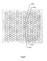
- a fourth plate is needed.
- This plate is represented on the figure 6 .
- the set of modifiable microscopic holes obtained using three plates and represented on the figure 4 in reference position constitutes a first intermediate assembly.
- the plate of the figure 6 constitutes a second intermediate set.
- the density of microscopic holes is maximum.
- the hole 1013 of the plate of the figure 6 is superimposed on the hole 1001 of the first intermediate set of the figure 4 , the number of microscopic holes per unit area is divided by 4.
- the training of the three identical plates represented figure 4 can be done by means of an iris diaphragm tracking system shown on the figures 7 and 8 .
- the plates of the figure 4 are the plates 1040, 1041, 1042 represented on the figure 8 .
- These plates are metal sheets stretched on circular retaining rings 1022, 1021, 1020 and carrying holes made for example by laser drilling.
- These three fixing rings are connected to two control rings 1023, 1024.
- the inner ring 1020 is connected to the control ring 1023 by a bar 1028 freely rotating about an axis 1029 fixed in the control ring 1023
- the inner ring 1020 is connected to the control ring 1024 by a bar 1026 freely rotating about an axis 1027 fixed in the control ring 1024.
- the housing 1031 of the axis 1027 is oversized so as to be able to conjugate a rotation and a translation with respect to the axis 1027.
- a tie rod 1030 is used to hold the housing 1031 in abutment on the axis 1027.
- the two other retaining rings are linked in a similar way to the bushings 1027. ordered. When the two control rings rotate simultaneously in opposite directions and by an equal angle, the three plates move in translation at an angle of 120 degrees between the directions of each axis of displacement, as indicated on FIG. figure 5 .
- the figure 8 also shows the fourth plate 1051 which is a sheet stretched on a retaining ring 1050.
- the retaining ring 1050 is mounted on a two-axis positioner.
- the plates 1051 and 1042 are themselves plated on thick glass plates 1052 and 1043. When the entire system is in position, the two glass plates 1052 and 1043 prevent deformations of the sheets (plates) 1042, 1041, 1040 , 1051 carrying microscopic holes.
- Plates bearing microscopic holes generally move in translation relative to each other along a single axis.
- This solution simplifies the system in that each plate moves relative to another along a single axis.
- a guide rail can be used to guide the plates.
- a macroscopic guide rail is difficult to achieve with the required accuracy.
- such a guide rail can be replaced by a set of microscopic guide rails. Examples of embodiments of the guide rails are described in the patent application PCT / FR02 / 01222 .
- This guide method can be adapted to the case where the plates are metal sheets, as in the second embodiment.
- male or female rails can be made on each side of each sheet.
- the glass plates are then replaced by the metal sheets.
- the scheme of the figure 9 is equivalent to that in Figure 14 of the application PCT / FR02 / 01222 but illustrates the case of plates consisting of thin metal sheets.
- the plate 1134 carries the male rail 1132 separated from the plate by a layer of protective resin 1133 used for the lithographic embodiment of the rail 1132.
- the plate 1137 carries the female rail 1138 made by lithography in a metal layer 1135 separated from the plate by a resin 1139. The space between the two plates is filled with a lubricating liquid.
- each plate Only one side of each plate has a guide rail, but it is possible to make one on each side of each plate.
- the guide rails separating each guided metal sheet from the two adjacent sheets participate in maintaining the shape of the metal sheets and in avoiding deformation.
- the sheet number 1051 of FIG. 17 can only be guided by this method if its movement is restricted to a single direction.
- the present set of microscopic holes can be used in a confocal microscope with multipoint illumination.
- a set of microscopic holes of the type described in the fourth embodiment replaces the set of microscopic holes used in the system described by the figure 1 patent number US5,239,178 it becomes possible to change the size of these microscopic holes.
- the microscopic hole array of the first embodiment of the present invention can replace, with the same effect, the network of microscopic holes used on the figure 3 patent US 5,978,095 .
- the diameter of the microscopic holes can be easily changed, which affects the speed / resolution compromise or speed / penetration depth in the sample.
Landscapes
- Physics & Mathematics (AREA)
- General Physics & Mathematics (AREA)
- Optics & Photonics (AREA)
- Analytical Chemistry (AREA)
- Chemical & Material Sciences (AREA)
- Engineering & Computer Science (AREA)
- Computer Vision & Pattern Recognition (AREA)
- General Engineering & Computer Science (AREA)
- Microscoopes, Condenser (AREA)
- Coils Or Transformers For Communication (AREA)
- Undergarments, Swaddling Clothes, Handkerchiefs Or Underwear Materials (AREA)
- Absorbent Articles And Supports Therefor (AREA)
- Control And Other Processes For Unpacking Of Materials (AREA)
- External Artificial Organs (AREA)
- Sampling And Sample Adjustment (AREA)
- Devices For Use In Laboratory Experiments (AREA)
- Manufacture Or Reproduction Of Printing Formes (AREA)
Claims (9)
- veränderliche Anordnung, welche eine Vielzahl von mikroskopischen Löchern (1200) umfasst und sich zum Filtern eines Lichtstrahlenbündels in einem Konfokalmikroskop eignet, dadurch gekennzeichnet, dass:- sie eine Vielzahl von Platten (1000) umfasst, die jeweils eine Vielzahl konstituierender Löcher (1001) enthalten,- jedes mikroskopische Loch resultiert aus der Überlagerung von konstituierenden Löchern jeder der genannten Platten,- jedes konstituierende Loch trägt zur Bildung höchstens eines mikroskopischen Lochs bei,- mindestens eine der genannten Platten sich verschieben lässt, sodass aus einer ersten Konfiguration eine zweite Konfiguration entsteht,- jedes mikroskopische Loch durch Überlagerung der jeweils gleichen konstituierenden Löcher in der ersten und der zweiten Konfiguration entsteht, und- sich die Größe der mikroskopischen Löcher in der zweiten Konfiguration von ihrer Größe in der ersten Konfiguration unterscheidet.
- veränderliche Anordnung gemäß Patentanspruch 1, in der jede der genannten Platten sich verschieben lässt, und in der sich die Position jeder der genannten Platten in der zweiten Konfiguration von ihrer Position in der ersten Konfiguration unterscheidet.
- veränderliche Anordnung gemäß einem der Patentansprüche 1 bis 2, wobei die Bewegung jeder Platte gegenüber einer anderen entlang einer einzigen Achse erfolgt.
- veränderliche Anordnung gemäß einem der Patentansprüche 1 bis 3, wobei die Platten durch mikroskopische Führungsschienen (1132, 1138) zueinander positioniert werden.
- veränderliche Anordnung gemäß einem der Patentansprüche 1 bis 4, in der die Platten durch eine Schicht eines transparenten flüssigen Gleitmittels voneinander getrennt sind.
- veränderliche Anordnung gemäß Patentanspruch 5, in der mindestens eine der Platten eine dünne Folie (1041) ist, welche konstituierende Löcher trägt, und in der sich diese dünne Folie zwischen zwei dicken Platten (1043, 1052) befindet, um eine Verformung der Folie zu verhindern.
- veränderliche Anordnung gemäß einem der Patentansprüche 1 bis 5, welche genau zwei bewegliche Platten umfasst, wobei jedes konstituierende Loch (401) quadratisch ist.
- veränderliche Anordnung gemäß einem der Patentansprüche 1 bis 6, welche genau drei Platten umfasst, wobei jedes konstituierende Loch (1001) sechseckig ist.
- veränderliche Anordnung gemäß einem der Patentansprüche 1 bis 6, welche mindestens drei Platten umfasst, und einen Irisblendenmechanismus (1020 - 1031) enthält, der sich zum Verschieben der Platten eignet.
Applications Claiming Priority (4)
| Application Number | Priority Date | Filing Date | Title |
|---|---|---|---|
| FR0104841A FR2823315A1 (fr) | 2001-04-10 | 2001-04-10 | Ensemble modifiable de trous microscopiques |
| PCT/FR2001/002890 WO2002023247A1 (fr) | 2000-09-18 | 2001-09-18 | Dispositif de balayage optique confocal |
| FR0200780A FR2830340B1 (fr) | 2001-01-23 | 2002-01-22 | Dispositif de balayage optique confocal |
| EP02724407A EP1417526B9 (de) | 2001-04-10 | 2002-04-09 | Veränderbare anordnung von mikroskopischen löchern |
Related Parent Applications (2)
| Application Number | Title | Priority Date | Filing Date |
|---|---|---|---|
| EP02724407A Division EP1417526B9 (de) | 2001-04-10 | 2002-04-09 | Veränderbare anordnung von mikroskopischen löchern |
| EP02724407.8 Division | 2002-04-09 |
Publications (2)
| Publication Number | Publication Date |
|---|---|
| EP1770426A1 EP1770426A1 (de) | 2007-04-04 |
| EP1770426B1 true EP1770426B1 (de) | 2010-02-17 |
Family
ID=41567237
Family Applications (1)
| Application Number | Title | Priority Date | Filing Date |
|---|---|---|---|
| EP06026140A Expired - Lifetime EP1770426B1 (de) | 2001-04-10 | 2002-04-09 | Veränderbare Anordnung von mikroskopischen Löchern |
Country Status (5)
| Country | Link |
|---|---|
| EP (1) | EP1770426B1 (de) |
| AT (1) | ATE458210T1 (de) |
| DE (1) | DE60235421D1 (de) |
| FR (1) | FR2828942B1 (de) |
| PT (1) | PT1417526E (de) |
Families Citing this family (1)
| Publication number | Priority date | Publication date | Assignee | Title |
|---|---|---|---|---|
| CN109826978B (zh) * | 2019-02-28 | 2024-08-02 | 常州那央生物科技有限公司 | 微反应用微孔流道构建方法、微反应组件及其工作方法 |
Family Cites Families (6)
| Publication number | Priority date | Publication date | Assignee | Title |
|---|---|---|---|---|
| JPH05217536A (ja) * | 1992-02-03 | 1993-08-27 | Hitachi Ltd | 電子顕微鏡の絞り装置 |
| DE19513350A1 (de) * | 1994-04-15 | 1995-10-19 | Zeiss Carl Fa | Filter zur Lichtsteuerung und optisches Gerät mit einem solchen Filter |
| JPH09265049A (ja) * | 1996-03-28 | 1997-10-07 | Dainippon Screen Mfg Co Ltd | 光学的読取り領域制限板およびモジュールならびにこれらを適用した画像読取り装置 |
| DE19807716C2 (de) * | 1998-02-24 | 2003-09-04 | Efim Kipernik | Lochbrille, die zwei Lochblenden mit verstellbaren Löchern aufweist |
| JP3721815B2 (ja) * | 1998-12-15 | 2005-11-30 | 富士ゼロックス株式会社 | 光学素子の製造方法 |
| DE19929958C1 (de) * | 1999-06-29 | 2000-11-16 | Kipernik Efim | Lochbrille mit oder ohne Linsen |
-
2002
- 2002-04-09 FR FR0204382A patent/FR2828942B1/fr not_active Expired - Lifetime
- 2002-04-09 AT AT06026140T patent/ATE458210T1/de not_active IP Right Cessation
- 2002-04-09 DE DE60235421T patent/DE60235421D1/de not_active Expired - Lifetime
- 2002-04-09 EP EP06026140A patent/EP1770426B1/de not_active Expired - Lifetime
- 2002-04-09 PT PT02724407T patent/PT1417526E/pt unknown
Also Published As
| Publication number | Publication date |
|---|---|
| PT1417526E (pt) | 2007-03-30 |
| DE60235421D1 (de) | 2010-04-01 |
| FR2828942A1 (fr) | 2003-02-28 |
| EP1770426A1 (de) | 2007-04-04 |
| FR2828942B1 (fr) | 2006-10-20 |
| ATE458210T1 (de) | 2010-03-15 |
Similar Documents
| Publication | Publication Date | Title |
|---|---|---|
| EP2591324B1 (de) | Wellenfrontanalysator mit flüssigkristall-mikrolinsen | |
| EP3160719B1 (de) | Vorrichtung zum dreidimensionalen drucken | |
| EP1417526B1 (de) | Veränderbare anordnung von mikroskopischen löchern | |
| EP1770426B1 (de) | Veränderbare Anordnung von mikroskopischen Löchern | |
| EP0121962B1 (de) | Vorrichtung zur optischen Kopplung zwischen Lichtwellenleitern | |
| EP0843836A1 (de) | Optische vorrichtungbzur homogenisierung eines laserstrahles | |
| EP1649314B1 (de) | Rasterabbildungseinrichtung für die konfokale mikroskopie mit bildsubstraktion | |
| FR3046112B1 (fr) | Procede de realisation d'images selectivement visibles en variant l'angle d'observation par gravure au travers d'un reseau lenticulaire | |
| WO2015040288A1 (fr) | Dispositif catadioptrique améliorant la visualisation d'une image placée devant un capteur solaire | |
| EP0653038B1 (de) | Verteilt beleuchtungsvorrichtung | |
| EP0754959A1 (de) | Mikroabtastelemente für optisches System | |
| EP4012476A1 (de) | Konfokales mikroskop mit photonen-umverteilung | |
| FR2823315A1 (fr) | Ensemble modifiable de trous microscopiques | |
| EP0551032B1 (de) | Elektronisches Fadenkreuz, Verfahren zur Erlangung einer grösseren Präzision bei dem Gebrauch eines elektronischen Fadenkreuzes, und seine Verwendung | |
| WO2024002600A1 (fr) | Dispositif optique de balayage d'un faisceau lumineux sur une pièce à usiner | |
| EP2473824B1 (de) | Feldkompensiertes interferometer | |
| EP0221606B1 (de) | Optisches Aufnahme- oder Projektionsgerät | |
| WO2011009802A1 (fr) | Composant optique transparent a microcuves | |
| EP4394485A1 (de) | Vorrichtung zum projizieren eines bildes, das von einem bildschirm gebildet wird | |
| FR2821169A1 (fr) | Microscope confocal rapide | |
| FR2820829A1 (fr) | Mircroscope confocal rapide | |
| FR2645657A1 (fr) | Phototraceur a faisceaux laser pour imprimer des films photographiques | |
| FR2819896A1 (fr) | Microscope confocal rapide | |
| BE345817A (de) | ||
| FR2826736A1 (fr) | Dispositif a balayage optique confocal |
Legal Events
| Date | Code | Title | Description |
|---|---|---|---|
| PUAI | Public reference made under article 153(3) epc to a published international application that has entered the european phase |
Free format text: ORIGINAL CODE: 0009012 |
|
| AC | Divisional application: reference to earlier application |
Ref document number: 1417526 Country of ref document: EP Kind code of ref document: P |
|
| AK | Designated contracting states |
Kind code of ref document: A1 Designated state(s): AT BE CH CY DE DK ES FI FR GB GR IE IT LI LU MC NL PT SE TR |
|
| 17P | Request for examination filed |
Effective date: 20071004 |
|
| 17Q | First examination report despatched |
Effective date: 20071006 |
|
| AKX | Designation fees paid |
Designated state(s): AT BE CH CY DE DK ES FI FR GB GR IE IT LI LU MC NL PT SE TR |
|
| R17C | First examination report despatched (corrected) |
Effective date: 20071106 |
|
| GRAP | Despatch of communication of intention to grant a patent |
Free format text: ORIGINAL CODE: EPIDOSNIGR1 |
|
| GRAS | Grant fee paid |
Free format text: ORIGINAL CODE: EPIDOSNIGR3 |
|
| GRAA | (expected) grant |
Free format text: ORIGINAL CODE: 0009210 |
|
| AC | Divisional application: reference to earlier application |
Ref document number: 1417526 Country of ref document: EP Kind code of ref document: P |
|
| AK | Designated contracting states |
Kind code of ref document: B1 Designated state(s): AT BE CH CY DE DK ES FI FR GB GR IE IT LI LU MC NL PT SE TR |
|
| REG | Reference to a national code |
Ref country code: GB Ref legal event code: FG4D Free format text: NOT ENGLISH |
|
| REG | Reference to a national code |
Ref country code: CH Ref legal event code: EP |
|
| REG | Reference to a national code |
Ref country code: IE Ref legal event code: FG4D Free format text: LANGUAGE OF EP DOCUMENT: FRENCH |
|
| REF | Corresponds to: |
Ref document number: 60235421 Country of ref document: DE Date of ref document: 20100401 Kind code of ref document: P |
|
| REG | Reference to a national code |
Ref country code: NL Ref legal event code: VDEP Effective date: 20100217 |
|
| PG25 | Lapsed in a contracting state [announced via postgrant information from national office to epo] |
Ref country code: PT Free format text: LAPSE BECAUSE OF FAILURE TO SUBMIT A TRANSLATION OF THE DESCRIPTION OR TO PAY THE FEE WITHIN THE PRESCRIBED TIME-LIMIT Effective date: 20100617 Ref country code: ES Free format text: LAPSE BECAUSE OF FAILURE TO SUBMIT A TRANSLATION OF THE DESCRIPTION OR TO PAY THE FEE WITHIN THE PRESCRIBED TIME-LIMIT Effective date: 20100528 |
|
| PG25 | Lapsed in a contracting state [announced via postgrant information from national office to epo] |
Ref country code: AT Free format text: LAPSE BECAUSE OF FAILURE TO SUBMIT A TRANSLATION OF THE DESCRIPTION OR TO PAY THE FEE WITHIN THE PRESCRIBED TIME-LIMIT Effective date: 20100217 Ref country code: FI Free format text: LAPSE BECAUSE OF FAILURE TO SUBMIT A TRANSLATION OF THE DESCRIPTION OR TO PAY THE FEE WITHIN THE PRESCRIBED TIME-LIMIT Effective date: 20100217 |
|
| REG | Reference to a national code |
Ref country code: IE Ref legal event code: FD4D |
|
| PG25 | Lapsed in a contracting state [announced via postgrant information from national office to epo] |
Ref country code: SE Free format text: LAPSE BECAUSE OF FAILURE TO SUBMIT A TRANSLATION OF THE DESCRIPTION OR TO PAY THE FEE WITHIN THE PRESCRIBED TIME-LIMIT Effective date: 20100217 Ref country code: IE Free format text: LAPSE BECAUSE OF FAILURE TO SUBMIT A TRANSLATION OF THE DESCRIPTION OR TO PAY THE FEE WITHIN THE PRESCRIBED TIME-LIMIT Effective date: 20100217 Ref country code: GR Free format text: LAPSE BECAUSE OF FAILURE TO SUBMIT A TRANSLATION OF THE DESCRIPTION OR TO PAY THE FEE WITHIN THE PRESCRIBED TIME-LIMIT Effective date: 20100518 Ref country code: NL Free format text: LAPSE BECAUSE OF FAILURE TO SUBMIT A TRANSLATION OF THE DESCRIPTION OR TO PAY THE FEE WITHIN THE PRESCRIBED TIME-LIMIT Effective date: 20100217 Ref country code: CY Free format text: LAPSE BECAUSE OF FAILURE TO SUBMIT A TRANSLATION OF THE DESCRIPTION OR TO PAY THE FEE WITHIN THE PRESCRIBED TIME-LIMIT Effective date: 20100217 |
|
| BERE | Be: lapsed |
Owner name: LAUER, VINCENT Effective date: 20100430 |
|
| PG25 | Lapsed in a contracting state [announced via postgrant information from national office to epo] |
Ref country code: MC Free format text: LAPSE BECAUSE OF NON-PAYMENT OF DUE FEES Effective date: 20100430 |
|
| REG | Reference to a national code |
Ref country code: CH Ref legal event code: PL |
|
| REG | Reference to a national code |
Ref country code: FR Ref legal event code: CA |
|
| PLBE | No opposition filed within time limit |
Free format text: ORIGINAL CODE: 0009261 |
|
| STAA | Information on the status of an ep patent application or granted ep patent |
Free format text: STATUS: NO OPPOSITION FILED WITHIN TIME LIMIT |
|
| 26N | No opposition filed |
Effective date: 20101118 |
|
| PG25 | Lapsed in a contracting state [announced via postgrant information from national office to epo] |
Ref country code: DK Free format text: LAPSE BECAUSE OF FAILURE TO SUBMIT A TRANSLATION OF THE DESCRIPTION OR TO PAY THE FEE WITHIN THE PRESCRIBED TIME-LIMIT Effective date: 20100217 |
|
| PG25 | Lapsed in a contracting state [announced via postgrant information from national office to epo] |
Ref country code: LI Free format text: LAPSE BECAUSE OF NON-PAYMENT OF DUE FEES Effective date: 20100430 Ref country code: CH Free format text: LAPSE BECAUSE OF NON-PAYMENT OF DUE FEES Effective date: 20100430 |
|
| PG25 | Lapsed in a contracting state [announced via postgrant information from national office to epo] |
Ref country code: IT Free format text: LAPSE BECAUSE OF FAILURE TO SUBMIT A TRANSLATION OF THE DESCRIPTION OR TO PAY THE FEE WITHIN THE PRESCRIBED TIME-LIMIT Effective date: 20100217 Ref country code: BE Free format text: LAPSE BECAUSE OF NON-PAYMENT OF DUE FEES Effective date: 20100430 |
|
| PG25 | Lapsed in a contracting state [announced via postgrant information from national office to epo] |
Ref country code: LU Free format text: LAPSE BECAUSE OF NON-PAYMENT OF DUE FEES Effective date: 20100409 |
|
| PG25 | Lapsed in a contracting state [announced via postgrant information from national office to epo] |
Ref country code: TR Free format text: LAPSE BECAUSE OF FAILURE TO SUBMIT A TRANSLATION OF THE DESCRIPTION OR TO PAY THE FEE WITHIN THE PRESCRIBED TIME-LIMIT Effective date: 20100217 |
|
| REG | Reference to a national code |
Ref country code: DE Ref legal event code: R081 Ref document number: 60235421 Country of ref document: DE Owner name: LAUER, VINCENT, FR Free format text: FORMER OWNER: LAUER, VINCENT, 44115 BASSE GOULAINE, FR Effective date: 20140410 Ref country code: DE Ref legal event code: R081 Ref document number: 60235421 Country of ref document: DE Owner name: LAUER, VINCENT, FR Free format text: FORMER OWNER: LAUER, VINCENT, MULHOUSE, FR Effective date: 20120723 |
|
| REG | Reference to a national code |
Ref country code: FR Ref legal event code: CA Effective date: 20140918 |
|
| REG | Reference to a national code |
Ref country code: FR Ref legal event code: PLFP Year of fee payment: 14 |
|
| PGFP | Annual fee paid to national office [announced via postgrant information from national office to epo] |
Ref country code: GB Payment date: 20151027 Year of fee payment: 14 Ref country code: DE Payment date: 20151028 Year of fee payment: 14 |
|
| PGFP | Annual fee paid to national office [announced via postgrant information from national office to epo] |
Ref country code: FR Payment date: 20151028 Year of fee payment: 14 |
|
| REG | Reference to a national code |
Ref country code: DE Ref legal event code: R119 Ref document number: 60235421 Country of ref document: DE |
|
| GBPC | Gb: european patent ceased through non-payment of renewal fee |
Effective date: 20160409 |
|
| REG | Reference to a national code |
Ref country code: FR Ref legal event code: ST Effective date: 20161230 |
|
| PG25 | Lapsed in a contracting state [announced via postgrant information from national office to epo] |
Ref country code: FR Free format text: LAPSE BECAUSE OF NON-PAYMENT OF DUE FEES Effective date: 20160502 Ref country code: DE Free format text: LAPSE BECAUSE OF NON-PAYMENT OF DUE FEES Effective date: 20161101 Ref country code: GB Free format text: LAPSE BECAUSE OF NON-PAYMENT OF DUE FEES Effective date: 20160409 |