EP1770426B1 - Modifiable assembly of microscopic apertures - Google Patents
Modifiable assembly of microscopic apertures Download PDFInfo
- Publication number
- EP1770426B1 EP1770426B1 EP06026140A EP06026140A EP1770426B1 EP 1770426 B1 EP1770426 B1 EP 1770426B1 EP 06026140 A EP06026140 A EP 06026140A EP 06026140 A EP06026140 A EP 06026140A EP 1770426 B1 EP1770426 B1 EP 1770426B1
- Authority
- EP
- European Patent Office
- Prior art keywords
- plates
- holes
- microscopic
- configuration
- modifiable
- Prior art date
- Legal status (The legal status is an assumption and is not a legal conclusion. Google has not performed a legal analysis and makes no representation as to the accuracy of the status listed.)
- Expired - Lifetime
Links
Images


Classifications
-
- G—PHYSICS
- G02—OPTICS
- G02B—OPTICAL ELEMENTS, SYSTEMS OR APPARATUS
- G02B21/00—Microscopes
- G02B21/0004—Microscopes specially adapted for specific applications
- G02B21/002—Scanning microscopes
- G02B21/0024—Confocal scanning microscopes (CSOMs) or confocal "macroscopes"; Accessories which are not restricted to use with CSOMs, e.g. sample holders
- G02B21/0032—Optical details of illumination, e.g. light-sources, pinholes, beam splitters, slits, fibers
-
- G—PHYSICS
- G02—OPTICS
- G02B—OPTICAL ELEMENTS, SYSTEMS OR APPARATUS
- G02B21/00—Microscopes
- G02B21/0004—Microscopes specially adapted for specific applications
- G02B21/002—Scanning microscopes
- G02B21/0024—Confocal scanning microscopes (CSOMs) or confocal "macroscopes"; Accessories which are not restricted to use with CSOMs, e.g. sample holders
- G02B21/0036—Scanning details, e.g. scanning stages
- G02B21/004—Scanning details, e.g. scanning stages fixed arrays, e.g. switchable aperture arrays
-
- G—PHYSICS
- G02—OPTICS
- G02B—OPTICAL ELEMENTS, SYSTEMS OR APPARATUS
- G02B21/00—Microscopes
- G02B21/0004—Microscopes specially adapted for specific applications
- G02B21/002—Scanning microscopes
- G02B21/0024—Confocal scanning microscopes (CSOMs) or confocal "macroscopes"; Accessories which are not restricted to use with CSOMs, e.g. sample holders
- G02B21/0036—Scanning details, e.g. scanning stages
- G02B21/0048—Scanning details, e.g. scanning stages scanning mirrors, e.g. rotating or galvanomirrors, MEMS mirrors
-
- G—PHYSICS
- G02—OPTICS
- G02B—OPTICAL ELEMENTS, SYSTEMS OR APPARATUS
- G02B21/00—Microscopes
- G02B21/0004—Microscopes specially adapted for specific applications
- G02B21/002—Scanning microscopes
- G02B21/0024—Confocal scanning microscopes (CSOMs) or confocal "macroscopes"; Accessories which are not restricted to use with CSOMs, e.g. sample holders
- G02B21/0052—Optical details of the image generation
- G02B21/0068—Optical details of the image generation arrangements using polarisation
-
- G—PHYSICS
- G02—OPTICS
- G02B—OPTICAL ELEMENTS, SYSTEMS OR APPARATUS
- G02B21/00—Microscopes
- G02B21/0004—Microscopes specially adapted for specific applications
- G02B21/002—Scanning microscopes
- G02B21/0024—Confocal scanning microscopes (CSOMs) or confocal "macroscopes"; Accessories which are not restricted to use with CSOMs, e.g. sample holders
- G02B21/0052—Optical details of the image generation
- G02B21/0076—Optical details of the image generation arrangements using fluorescence or luminescence
-
- G—PHYSICS
- G02—OPTICS
- G02B—OPTICAL ELEMENTS, SYSTEMS OR APPARATUS
- G02B21/00—Microscopes
- G02B21/0004—Microscopes specially adapted for specific applications
- G02B21/002—Scanning microscopes
- G02B21/0024—Confocal scanning microscopes (CSOMs) or confocal "macroscopes"; Accessories which are not restricted to use with CSOMs, e.g. sample holders
- G02B21/008—Details of detection or image processing, including general computer control
- G02B21/0084—Details of detection or image processing, including general computer control time-scale detection, e.g. strobed, ultra-fast, heterodyne detection
-
- G—PHYSICS
- G02—OPTICS
- G02B—OPTICAL ELEMENTS, SYSTEMS OR APPARATUS
- G02B5/00—Optical elements other than lenses
- G02B5/005—Diaphragms
Definitions
- the invention relates to a microscopic hole or a set of microscopic holes (in English "pinhole"), the number of these holes and / or their size can be easily modified.
- a set of microscopic holes is intended to be used for various applications in optics, and in particular in confocal microscopy.
- a network of microscopic holes must be positioned with great precision, which is difficult using a simple technique of exchanging the entire network.
- "single" microscopic holes are simply exchanged as on some monopoint confocal microscopes, their precise positioning is also difficult.
- the microscopic hole network exchange systems are necessarily bulky, since their size is the sum of the congestion of each network that can be exchanged.
- corners are not holes since they are inbound corners open on one side.
- the microscopic hole is here unique and therefore not suitable for a multipoint confocal microscope.
- the subject of the invention is a set of several microscopic holes of variable size, the modifications of which are obtained by a simplified, precise and inexpensive method.
- an object of the invention is to provide a modifiable microscopic hole without problems of positioning and reduced bulk.
- holes is meant holes in the optical sense of the term, that is to say, small areas passable by the light, not necessarily empty.
- a "hole” can be for example an interruption of opaque layer deposited on glass.
- An iris diaphragm also has slidable plates relative to each other.
- the invention is distinguished by the fact that these plates carry microscopic holes, and in that one of the plates carries at least two microscopic holes. This particular arrangement makes it possible to simplify the construction of the system and makes it possible to produce modifiable microscopic hole arrays, whereas the iris diaphragms are designed only for a single modifiable microscopic hole.
- An editable set of microscopic holes can also be obtained by a system physically exchanging two sets of microscopic holes made on different plates.
- This solution is used in some single point confocal microscopes.
- the present invention differs from this simple technical solution by the use of several superposed plates, which makes it possible to modify the network of microscopic holes by means of displacements which are also microscopic, and not macroscopic as is the case in the state of art. This simplifies positioning problems.
- two of said plates may be transparent panes on which said microscopic holes are made by depositing an opaque layer by a lithographic method.
- the opaque layers of these two plates can then be turned towards each other, so that the space between them is as small as possible.
- the advantage of this technique is that the windows have a good rigidity (deform little).
- At least one of the plates is a thin opaque sheet in which said microscopic holes are obtained by drilling. This solution is needed when more than two plates are used. Indeed, if we only use glass plates, their thickness does not allow the realization in good conditions of a network of holes.
- the plates consisting of thin opaque sheets are placed against each other and clamped between two thick plates, to avoid deformation of said plates consisting of thin opaque sheets.
- a difficulty of realization is the tendency to deformation of thin sheets, which do not have the necessary rigidity and must therefore be placed between thicker supports.
- the plates are separated from each other by layers of a transparent lubricating liquid. Indeed, in the opposite case, the friction between the plates make it difficult to function properly.
- Another solution is to use plates that do not touch each other, but this solution is difficult because it requires excellent flatness of the plates.
- the sliding of a plate relative to one another can generally be done along two axes.
- the system is simplified, according to a feature of the invention, if this sliding is along only one axis. In this case, it is possible to use a guide rail to facilitate the maintenance of correct relative positioning of the plates.
- a rail is expensive and poses positioning problems.
- two adjacent plates sliding one with respect to the other along an axis are positioned relative to one another by microscopic guide rails.
- a microscopic rail is fragile, it is preferable, according to one characteristic of the invention, to use several microscopic guide rails. These rails can for example be made by lithography.
- an appropriate solution to this problem is to continuously move the plates relative to one another so that this continuous displacement results in a continuous modification of the surface of each microscopic hole of the modifiable assembly.
- the microscopic holes are preferably polygons with 2N sides, although they can also have other shapes, for example circular.
- the directions of displacement in translation of the plates relative to each other are then preferably directed along the mediators of the polygons.
- the sliding of the plates relative to each other is obtained using an iris diaphragm mechanism.
- This solution is well adapted to the previous case, or it allows to coordinate the continuous displacement of several plates.
- This iris diaphragm mechanism may, in the event that a rotation of the set of microscopic holes is to be avoided, be supplemented by an additional rotation device to compensate for the rotation generated by a single element iris diaphragm mechanism. mobile.
- one of the plates is moved by means of a linear positioner axis.
- This solution is preferred when a technique based on discrete movements is used. It may also be necessary to move one of the plates by means of a two-axis positioner. This solution is the one that allows maximum flexibility.
- the modifiable set of microscopic holes can easily be achieved by means of only two plates. In this case it can be thick transparent plates on which the hole networks are made by a litographic method. This solution is the simplest, in particular because the plates do not deform. However, when the density of microscopic holes is high, it becomes necessary to use more than two plates as we saw above.
- This first embodiment makes it possible to obtain square holes of continuously variable size. It uses two identical plates and represented for example by the figure 1 . When the hole 401 of the first plate is exactly superimposed on the hole 401 of the second plate, a set of square holes equivalent to the first single plate is obtained. When the two plates are moved relative to each other along the axis 402, the size of the square holes resulting from the superposition of the plates is reduced.
- the two plates moving relative to each other can be separated by a layer of optical liquid.
- the system can be sealed as shown on the figure 2 by means of a flexible closure 500, for example plastic, which closes the entire system.
- the liquid can then be injected under vacuum between the two plates and in the zone comprised within the flexible closure 500.
- This device reconciles the movement of the plates 110 and 100 with the absence of liquid leaks.
- An alternative to the vacuum filling is the overflow system shown in FIG. 15.
- a tube 501 leads into a tank 502 with an elevated air intake and maintains a level of optical liquid in the tank. area between the plates.
- This second embodiment is particularly suitable in the case where a high density of microscopic holes is sought. Although more complex than the first embodiment, it allows the realization of hexagonal microscopic holes, which is preferable to square microscopic holes. In a basic version, it requires the use of 3 plates that move continuously relative to each other to others. They are driven by means of a modified iris diaphragm device to compensate for the rotation of the assembly.
- the microscopic holes are hexagonal.
- the three plates carry networks of identical holes which, in a reference position, are superimposed on each other.
- the figure 4 shows a plate 1000 having microscopic holes, for example 1001.
- the shape of the modifiable set of microscopic holes is the same as the pace of each of the plates and is therefore represented by the figure 4 .
- the size of the holes of the modifiable set of microscopic holes is modified by moving the plates relative to each other in the manner indicated by the figure 5 .
- This figure represents a part of the network of microscopic holes.
- the dotted lines represent the limits of the microscopic holes of each of the three plates and the intersection of these holes, which constitutes the effective hole of the modifiable network, is shown in white (for example, 1200).
- the arrows show the direction of movement of the plates from the reference position. Moving the plates in the direction of the arrows continuously decreases the width of the holes.
- a fourth plate is needed.
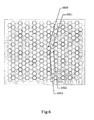
- This plate is represented on the figure 6 .
- the set of modifiable microscopic holes obtained using three plates and represented on the figure 4 in reference position constitutes a first intermediate assembly.
- the plate of the figure 6 constitutes a second intermediate set.
- the density of microscopic holes is maximum.
- the hole 1013 of the plate of the figure 6 is superimposed on the hole 1001 of the first intermediate set of the figure 4 , the number of microscopic holes per unit area is divided by 4.
- the training of the three identical plates represented figure 4 can be done by means of an iris diaphragm tracking system shown on the figures 7 and 8 .
- the plates of the figure 4 are the plates 1040, 1041, 1042 represented on the figure 8 .
- These plates are metal sheets stretched on circular retaining rings 1022, 1021, 1020 and carrying holes made for example by laser drilling.
- These three fixing rings are connected to two control rings 1023, 1024.
- the inner ring 1020 is connected to the control ring 1023 by a bar 1028 freely rotating about an axis 1029 fixed in the control ring 1023
- the inner ring 1020 is connected to the control ring 1024 by a bar 1026 freely rotating about an axis 1027 fixed in the control ring 1024.
- the housing 1031 of the axis 1027 is oversized so as to be able to conjugate a rotation and a translation with respect to the axis 1027.
- a tie rod 1030 is used to hold the housing 1031 in abutment on the axis 1027.
- the two other retaining rings are linked in a similar way to the bushings 1027. ordered. When the two control rings rotate simultaneously in opposite directions and by an equal angle, the three plates move in translation at an angle of 120 degrees between the directions of each axis of displacement, as indicated on FIG. figure 5 .
- the figure 8 also shows the fourth plate 1051 which is a sheet stretched on a retaining ring 1050.
- the retaining ring 1050 is mounted on a two-axis positioner.
- the plates 1051 and 1042 are themselves plated on thick glass plates 1052 and 1043. When the entire system is in position, the two glass plates 1052 and 1043 prevent deformations of the sheets (plates) 1042, 1041, 1040 , 1051 carrying microscopic holes.
- Plates bearing microscopic holes generally move in translation relative to each other along a single axis.
- This solution simplifies the system in that each plate moves relative to another along a single axis.
- a guide rail can be used to guide the plates.
- a macroscopic guide rail is difficult to achieve with the required accuracy.
- such a guide rail can be replaced by a set of microscopic guide rails. Examples of embodiments of the guide rails are described in the patent application PCT / FR02 / 01222 .
- This guide method can be adapted to the case where the plates are metal sheets, as in the second embodiment.
- male or female rails can be made on each side of each sheet.
- the glass plates are then replaced by the metal sheets.
- the scheme of the figure 9 is equivalent to that in Figure 14 of the application PCT / FR02 / 01222 but illustrates the case of plates consisting of thin metal sheets.
- the plate 1134 carries the male rail 1132 separated from the plate by a layer of protective resin 1133 used for the lithographic embodiment of the rail 1132.
- the plate 1137 carries the female rail 1138 made by lithography in a metal layer 1135 separated from the plate by a resin 1139. The space between the two plates is filled with a lubricating liquid.
- each plate Only one side of each plate has a guide rail, but it is possible to make one on each side of each plate.
- the guide rails separating each guided metal sheet from the two adjacent sheets participate in maintaining the shape of the metal sheets and in avoiding deformation.
- the sheet number 1051 of FIG. 17 can only be guided by this method if its movement is restricted to a single direction.
- the present set of microscopic holes can be used in a confocal microscope with multipoint illumination.
- a set of microscopic holes of the type described in the fourth embodiment replaces the set of microscopic holes used in the system described by the figure 1 patent number US5,239,178 it becomes possible to change the size of these microscopic holes.
- the microscopic hole array of the first embodiment of the present invention can replace, with the same effect, the network of microscopic holes used on the figure 3 patent US 5,978,095 .
- the diameter of the microscopic holes can be easily changed, which affects the speed / resolution compromise or speed / penetration depth in the sample.
Abstract
Description
L'invention concerne un trou microscopique ou un ensemble de trous microscopiques ( en anglais "pinhole" ), le nombre de ces trous et/ou leur taille pouvant être aisément modifié. Un tel ensemble de trous microscopiques est destiné à être utilisé pour diverses applications en optique, et en particulier en microscopie confocale.The invention relates to a microscopic hole or a set of microscopic holes (in English "pinhole"), the number of these holes and / or their size can be easily modified. Such a set of microscopic holes is intended to be used for various applications in optics, and in particular in confocal microscopy.
En microscopie confocale on utilise usuellement deux types de trous microscopiques:
- des trous de taille fixe: pour modifier la taille d'un trou, il est nécessaire de le remplaçer par un autre. Typiquement plusieurs trous microscopiques peuvent être montés sur une roue ayant une position correspondant à l'utilisation de chacun de ces trous. Le mouvement de la roue doit être très précis.
- des trous de taille variable: fonctionnant sur le principe du diaphragme à iris, ils nécessitent au moins trois lames qui forment un trou en se croisant et sont coûteux du fait de la relative complexité du mécanisme.
- fixed size holes: to change the size of a hole, it is necessary to replace it with another one. Typically several microscopic holes may be mounted on a wheel having a position corresponding to the use of each of these holes. The movement of the wheel must be very precise.
- holes of variable size: operating on the principle of the iris diaphragm, they require at least three blades that form a hole crossing and are expensive because of the relative complexity of the mechanism.
Classiquement, les systèmes de microscopie confocale nécessitent l'utilisation d'un seul trou microscopique. Par exemple le premier mode de réalisation de la demande de brevet français numéro
D'autres systèmes de microscopie confocale nécessitent l'utilisation d'un réseau de trous microscopiques. Par exemple les microscopes décrits par la
Dans certains modes de réalisation d'un microscope tel que celui décrit dans la demande de brevet français numéro
Dans le cas des microscopes utilisant un réseau de trous microscopiques la taille et la densité des trous ne peuvent usuellement pas être modifiés. Pourtant cette modification est souhaitable pour adapter la taille des trous à la longueur d'onde étudiée. Le brevet numéro
Le brevet allemand
- il comprend une pluralité de plaques comprenant chacune une pluralité de trous intermédiaires,
- chaque trou modifiable résulte de la superposition de trous intermédiaires de chacune dedites plaques,
- chaque trou intermédiaire contribue à la formation d'au plus un trou modifiable,
- au moins une dedites plaques est adaptée pour se déplacer, pour passer d'une première configuration à une seconde configuration,
- chaque trous modifiable résulte de la superposition des mêmes trous inrtermédiaires dans la seconde configuration que dans la première configuration, et
- la taille des trous microscopiques dans la seconde configuration diffère de leur taille dans la première configuration.
- it comprises a plurality of plates each comprising a plurality of intermediate holes,
- each modifiable hole results from the superposition of intermediate holes of each of said plates,
- each intermediate hole contributes to the formation of at most one modifiable hole,
- at least one of said plates is adapted to move, to go from a first configuration to a second configuration,
- each modifiable hole results from the superposition of the same intermediate holes in the second configuration as in the first configuration, and
- the size of the microscopic holes in the second configuration differs from their size in the first configuration.
Toutefois ces trous ne sont pas de taille microscopique (leur taille est typiquement comprise entre 0,5 mm at 4 mm alors qu'une taille typique est de 50 microns pour le filtrage d'un faisceau lumineux dans un microscope confocal) et l'ensemble n'est donc pas adapté pour filtrer un faisceau lumineux dans un microscope confocal. Cet ensemble vise à la réalisation de lunettes et non d'un microscope confocal.However these holes are not microscopic size (their size is typically between 0.5 mm and 4 mm whereas a typical size is 50 microns for filtering a light beam in a confocal microscope) and all is not suitable for filtering a light beam in a confocal microscope. This set is aimed at producing glasses and not a confocal microscope.
Le brevet
- il comprend une pluralité de plaques,
- le trou microscopique résulte de la superposition de coins rentrants découpés dans chacune desdites plaques,
- chaque coin contribue à la formation du un trou microscopique,
- au moins une dedites plaques est adaptée pour se déplacer, pour passer d'une première configuration à une seconde configuration,
- le trou microscopique résulte de la superposition des mêmes coins rentrants dans la seconde configuration que dans la première configuration, et
- la taille du trou microscopique dans la seconde configuration diffère de sa taille dans la première configuration.
- it comprises a plurality of plates,
- the microscopic hole results from the superposition of inside corners cut in each of said plates,
- each corner contributes to the formation of a microscopic hole,
- at least one of said plates is adapted to move, to go from a first configuration to a second configuration,
- the microscopic hole results from the superposition of the same reentrant corners in the second configuration as in the first configuration, and
- the size of the microscopic hole in the second configuration differs from its size in the first configuration.
Toutefois les coins ne sont pas des trous puisque il s'agit de coins entrants ouverts d'un coté. De plus le trou microscopique est ici unique et donc non adapté à un microscope confocal multipoints.However, corners are not holes since they are inbound corners open on one side. In addition, the microscopic hole is here unique and therefore not suitable for a multipoint confocal microscope.
L'invention a pour objet un ensemble de plusieurs trous microscopiques de taille variable, dont les modifications sont obtenues par une méthode simplifiée, précise et peu coûteuse. En particulier, un objet de l'invention est de réaliser un trous microscopiques modifiable sans problèmes de positionnement et d'un encombrement réduit. Par "trous" on entend trous au sens optique du terme, c'est-à-dire petites zones traversables par la lumière, non nécessairement vides. Un "trou" peut être par exemple une interruption de couche opaque déposée sur du verre.The subject of the invention is a set of several microscopic holes of variable size, the modifications of which are obtained by a simplified, precise and inexpensive method. In particular, an object of the invention is to provide a modifiable microscopic hole without problems of positioning and reduced bulk. By "holes" is meant holes in the optical sense of the term, that is to say, small areas passable by the light, not necessarily empty. A "hole" can be for example an interruption of opaque layer deposited on glass.
A cet effet, l'invention a pour objet un ensemble modifiable comprenant une pluralité de trous microscopiques et adapté pour filtrer un faisceau lumineux dans un microscope confocal, caractérisé par les faits suivants :
- il comprend une pluralité de plaques comprenant chacune une pluralité de trous intermédiaires,
- chaque trou microscopique résulte de la superposition de trous intermédiaires de chacune dedites plaques,
- chaque trou intermédiaire contribue à la formation d'au plus un trou microscopique,
- au moins une dedites plaques est adaptée pour se déplacer, pour passer d'une première configuration à une seconde configuration,
- chaque trous microscopique résulte de la superposition des mêmes trous intermédiaires dans la seconde configuration que dans la première configuration, et
- la taille des trous microscopiques dans la seconde configuration diffère de leur taille dans la première configuration.
- it comprises a plurality of plates each comprising a plurality of intermediate holes,
- each microscopic hole results from the superposition of intermediate holes of each of said plates,
- each intermediate hole contributes to the formation of at most one microscopic hole,
- at least one of said plates is adapted to move, to go from a first configuration to a second configuration,
- each microscopic hole results from the superposition of the same intermediate holes in the second configuration as in the first configuration, and
- the size of the microscopic holes in the second configuration differs from their size in the first configuration.
Un diaphragme iris comporte également des plaques glissant les unes par rapport aux autres. L'invention s'en distingue par le fait que ces plaques portent des trous microscopiques, et par le fait qu'une des plaques porte au moins deux trous microscopiques. Cette disposition particulière permet de simplifier la réalisation du système et rend possible la réalisation de réseaux de trous microscopiques modifiables, alors que les diaphragmes à iris ne sont conçus que pour un trou microscopique modifiable unique.An iris diaphragm also has slidable plates relative to each other. The invention is distinguished by the fact that these plates carry microscopic holes, and in that one of the plates carries at least two microscopic holes. This particular arrangement makes it possible to simplify the construction of the system and makes it possible to produce modifiable microscopic hole arrays, whereas the iris diaphragms are designed only for a single modifiable microscopic hole.
Un ensemble modifiable de trous microscopiques peut également être obtenu par un système échangeant physiquement deux ensembles de trous microscopiques réalisés sur des plaques différentes. Cette solution est utilisée dans certains microscopes confocaux monopoint. La présente invention se distingue de cette solution technique simple par l'utilisation de plusieurs plaques superposées, ce qui permet de modifier le réseau de trous microscopiques au moyen de déplacements également microscopiques, et non macroscopiques comme c'est le cas dans l'état de l'art. Ceci simplifie les problèmes de positionnement.An editable set of microscopic holes can also be obtained by a system physically exchanging two sets of microscopic holes made on different plates. This solution is used in some single point confocal microscopes. The present invention differs from this simple technical solution by the use of several superposed plates, which makes it possible to modify the network of microscopic holes by means of displacements which are also microscopic, and not macroscopic as is the case in the state of art. This simplifies positioning problems.
Différentes techniques de réalisation des plaques peuvent être employées. Par exemple, et suivant une caractéristique de l'invention, deux desdites plaques peuvent être des vitres transparentes sur lesquelles lesdits trous microscopiques sont réalisées par dépôt d'une couche opaque par une méthode litographique. Les couches opaques de ces deux plaques peuvent alors être tournées l'une vers l'autre, pour que l'espace les séparant soit aussi réduit que possible. L'avantage de cette technique est que les vitres ont une bonne rigidité (se déforment peu).Different techniques for producing the plates can be used. For example, and according to a feature of the invention, two of said plates may be transparent panes on which said microscopic holes are made by depositing an opaque layer by a lithographic method. The opaque layers of these two plates can then be turned towards each other, so that the space between them is as small as possible. The advantage of this technique is that the windows have a good rigidity (deform little).
Suivant une caractéristique de l'invention, au moins une des plaques est une feuille opaque fine dans laquelle lesdits trous microscopiques sont obtenus par perçage. Cette solution s'impose lorsque plus de deux plaques sont utilisées. En effet, si on utilise uniquement des plaques en verre, leur épaisseur ne permet pas la réalisation dans de bonnes conditions d'un réseau de trous.According to a feature of the invention, at least one of the plates is a thin opaque sheet in which said microscopic holes are obtained by drilling. This solution is needed when more than two plates are used. Indeed, if we only use glass plates, their thickness does not allow the realization in good conditions of a network of holes.
Suivant une caractéristique de l'invention, les plaques constituées de feuilles opaques fines sont placées les unes contre les autres et serrées entre deux plaques épaisses, pour éviter une déformation desdites plaques constituées de feuilles opaques fines. En effet une difficulté de réalisation est la tendance à la déformation des feuilles fines, qui n'ont pas la rigidité nécessaire et doivent donc être plaçées entre des supports plus épais.According to one characteristic of the invention, the plates consisting of thin opaque sheets are placed against each other and clamped between two thick plates, to avoid deformation of said plates consisting of thin opaque sheets. Indeed a difficulty of realization is the tendency to deformation of thin sheets, which do not have the necessary rigidity and must therefore be placed between thicker supports.
Suivant une caractéristique de l'invention, les plaques sont séparées les unes des autres par des couches d'un liquide lubrifiant transparent. En effet, dans le cas contraire, les frottements entre les plaques rendent difficile un fonctionnement correct. Une autre solution est d'utiliser des plaques qui ne se touchent pas les unes les autres, mais cette solution est difficile car elle nécessite une excellente planéité des plaques. Le glissement d'une plaque l'une par rapport à une autre peut en général se faire suivant deux axes. Toutefois, le système est simplifié, selon une caractéristique de l'invention, si ce glissement se fait suivant seulement un axe. Dans ce cas, il est possible d'utiliser un rail de guidage pour faciliter le maintien d'un positionnement relatif correct des plaques. Toutefois un tel rail est coûteux et pose des problèmes de positionnement. Pour faciliter le positionnement relatif des plaques, et selon une caractéristique de l'invention, deux plaques adjacentes glissant l'une par rapport à l'autre suivant un axe sont positionnées l'une par rapport à l'autre par des rails de guidage microscopiques. Un rail microscopique étant fragile, il est préférable, suivant une caractéristique de l'invention, d'utiliser plusieurs rails de guidage microscopiques. Ces rails peuvent par exemple être réalisés par litographie.According to one characteristic of the invention, the plates are separated from each other by layers of a transparent lubricating liquid. Indeed, in the opposite case, the friction between the plates make it difficult to function properly. Another solution is to use plates that do not touch each other, but this solution is difficult because it requires excellent flatness of the plates. The sliding of a plate relative to one another can generally be done along two axes. However, the system is simplified, according to a feature of the invention, if this sliding is along only one axis. In this case, it is possible to use a guide rail to facilitate the maintenance of correct relative positioning of the plates. However, such a rail is expensive and poses positioning problems. To facilitate the relative positioning of the plates, and according to one characteristic of the invention, two adjacent plates sliding one with respect to the other along an axis are positioned relative to one another by microscopic guide rails. . Since a microscopic rail is fragile, it is preferable, according to one characteristic of the invention, to use several microscopic guide rails. These rails can for example be made by lithography.
Différentes solutions peuvent être utilisées pour l'agencement des plaques et la répartition des trous sur les plaques.Different solutions can be used for the arrangement of the plates and the distribution of the holes on the plates.
Selon une caractéristique de l'invention, une solution appropriée à ce problème consiste à déplaçer continument les plaques les unes par rapport aux autres, pour que ce déplacement continu se traduise par une modification continue de la surface de chaque trou microscopique de l'ensemble modifiable. On peut par exemple utiliser plusieurs plaques identiques et une position de référence pour laquelle les trous microscopiques desdites plusieurs plaques sont exactement superposés les uns aux autres. Pour que la diminution de taille des trous microscopiques se fasse régulièrement, il est préférable de générer un déplacement en translation de la i-ième plaque suivant une direction orientée à ![]()
![]()
Suivant une caractéristique de l'invention, le glissement des plaques les unes par rapport aux autres est obtenu à l'aide d'un mécanisme de diaphragme à iris. Cette solution est bien adaptée au cas précédent, ou elle permet de coordonner le déplacement continu de plusieurs plaques. Ce mécanisme de diaphragme à iris peut, dans le cas ou une rotation de l'ensemble de trous microscopiques doit être évitée, être complété par un dispositif de rotation supplémentaire permettant de compenser la rotation engendrée par un mécanisme de diaphragme à iris à un seul élément mobile.According to a characteristic of the invention, the sliding of the plates relative to each other is obtained using an iris diaphragm mechanism. This solution is well adapted to the previous case, or it allows to coordinate the continuous displacement of several plates. This iris diaphragm mechanism may, in the event that a rotation of the set of microscopic holes is to be avoided, be supplemented by an additional rotation device to compensate for the rotation generated by a single element iris diaphragm mechanism. mobile.
Suivant une caractéristique de l'invention, une des plaques est déplaçée au moyen d'un positionneur linéaire en axe. Cette solution est préférée lorsque une technique à base de déplacements discrets est utilisée. Il peut également être nécessaire de déplacer une des plaques au moyen d'un positionneur deux axes. Cette solution est celle qui permet le maximum de flexibilité.According to a feature of the invention, one of the plates is moved by means of a linear positioner axis. This solution is preferred when a technique based on discrete movements is used. It may also be necessary to move one of the plates by means of a two-axis positioner. This solution is the one that allows maximum flexibility.
Lorsque la densité de trous microscopiques recherchée est faible, et selon une caractéristique de l'invention, l'ensemble modifiable de trous microscopiques peut aisément être réalisé au moyen de deux plaques seulement. Dans ce cas il peut s'agir de plaques transparentes épaisses sur lesquels les réseaux de trous sont réalisés par une méthode litographique. Cette solution est la plus simple, en particulier du fait que les plaques ne se déforment pas. Toutefois, lorsque la densité de trous microscopiques est élevée, il devient nécessaire d'utiliser plus de deux plaques ainsi qu'on l'a vu plus haut.When the desired density of microscopic holes is low, and according to a feature of the invention, the modifiable set of microscopic holes can easily be achieved by means of only two plates. In this case it can be thick transparent plates on which the hole networks are made by a litographic method. This solution is the simplest, in particular because the plates do not deform. However, when the density of microscopic holes is high, it becomes necessary to use more than two plates as we saw above.
-
La
figure 1 représente une plaque utilisée dans un premier mode de réalisation.Thefigure 1 represents a plate used in a first embodiment. -
La
figure 2 représente un dispositif utilisé pour éviter des fuites du liquide séparant les plaques, le dispositif étant rempli sous vide. Lafigure 3 représente un dispositif similaire mais comportant un trop-plein ayant une prise d'air.Thefigure 2 represents a device used to prevent leakage of the liquid separating the plates, the device being filled under vacuum. Thefigure 3 represents a similar device but having an overflow having an air intake. -
La
figure 4 représente une plaque utilisée dans un second mode de réalisation. Lafigure 5 illustre le déplacement de 3 plaques dans ce mode de réalisation. Lafigure 6 montre une plaque supplémentaire utilisée dans ce mode de réalisation. Lafigure 7 montre en vue de face le dispositif d'entraînement de 3 plaques identiques sur le principe de lafigure 5 . Lafigure 8 montre ce dispositif en coupe, complété par une quatrième plaque.Thefigure 4 represents a plate used in a second embodiment. Thefigure 5 illustrates the displacement of 3 plates in this embodiment. Thefigure 6 shows an additional plate used in this embodiment. Thefigure 7 shows in front view the drive device of 3 identical plates on the principle of thefigure 5 . Thefigure 8 shows this device in section, completed by a fourth plate. -
La
figure 9 représente en coupe l'assemblage de deux plaques réalisées sur des feuilles métalliques.Thefigure 9 represents in section the assembly of two plates made on metal sheets.
Ce premier mode de réalisation permet l'obtention de trous carrés de taille continûment variable. Il utilise deux plaques identiques et représentées par exemple par la
Les deux plaques se déplaçant l'une par rapport à l'autre peuvent être séparées par une couche de liquide optique. Le système peut être rendu étanche comme indiqué sur la
Ce second mode de réalisation est particulièrement adapté au cas ou une densité élevée de trous microscopiques est recherchée. Bien qu'étant plus complexe que le premier mode de réalisation il permet la réalisation de trous microscopiques hexagonaux, ce qui est préférable à des trous microscopiques carrés. Dans une version de base, il nécessite l'utilisation de 3 plaques qui se déplacent continument les unes par rapport aux autres. Elles sont entraînées au moyen d'un dispositif de diaphragme à iris modifié pour compenser la rotation de l'ensemble. Les trous microscopiques sont hexagonaux.This second embodiment is particularly suitable in the case where a high density of microscopic holes is sought. Although more complex than the first embodiment, it allows the realization of hexagonal microscopic holes, which is preferable to square microscopic holes. In a basic version, it requires the use of 3 plates that move continuously relative to each other to others. They are driven by means of a modified iris diaphragm device to compensate for the rotation of the assembly. The microscopic holes are hexagonal.
Les trois plaques portent des réseaux de trous identiques qui, dans une position de référence, sont superposés les uns aux autres. La
La taille des trous de l'ensemble modifiable de trous microscopiques est modifiée en déplaçant les plaques les unes par rapport aux autres de la manière indiquée par la
Dans une version permettant de modifier également la densité de trous microscopiques, une quatrième plaque est nécessaire. Cette plaque est représentée sur la
L'entraînement des trois plaques identiques représentées
La
Les plaques 1051 et 1042 sont elles-mêmes plaquées sur des plaques de verre épaisses 1052 et 1043. Lorsque l'ensemble du système est en position les deux plaques de verre 1052 et 1043 évitent des déformations des feuilles (plaques) 1042,1041,1040,1051 portant des trous microscopiques.The
Les plaques portant des trous microscopiques se déplacent généralement en translation les unes par rapport aux autres suivant un axe unique. Par exemple dans ie premier mode de réalisation, le deuxième, le quatrième mode de réalisation, mais également dans le cinquième mode de réalisation en ce qui concerne les trois plaques se déplaçant au moyen d'un mécanisme de diaphragme à iris. Cette solution simplifie le système en ce chaque plaque se déplace par rapport à une autre suivant un axe unique. Ainsi qu'indiqué plus haut un rail de guidage peut être utilisé pour guider les plaques. Toutefois, un rail de guidage macroscopique est difficile à réaliser avec la précision requise. Afin d'obtenir un bon positionnement des plaques on peut remplaçer un tel rail de guidage par un ensemble de rails de guidage microscopiques. Des exemples de réalisation des rails de guidage sont décrits dans la demande de brevet
Cette méthode de guidage peut être adaptée au cas ou les plaques sont des feuilles métalliques, comme dans le second mode de réalisation. Dans ce cas des rails mâle ou femelle peuvent être réalisés de chaque coté de chaque feuille. Les plaques en verre sont alors remplaçées par les feuilles métalliques. Le schéma de la
Le présent ensemble de trous microscopiques peut être utilisé dans un microscope confocal à éclairage multipoint. Par exemple si un ensemble de trous microscopiques du type décrit dans le quatrième mode de réalisation remplace l'ensemble de trous microscopiques utilisé dans le système décrit par la
Claims (9)
- modifiable assembly comprising a plurality of microscopic holes (1200) and adapted to filter a light beam in a confocal microscope, characterized by the following facts:- it comprises a plurality of plates (1000), wherein each plate comprises a plurality of intermediate holes (1001),- each microscopic hole is made up of superimposed intermediate holes from each of said plates,- each intermediate hole is part of at most one microscopic hole,- at least one of said plates is adapted to move, for switching from a first configuration to a second configuration,- in the second configuration each microscopic hole is made up of the superimposition of the same intermediate holes as in the first configuration, and- the size of the microscopic holes in the second configuration differs from their size in the first configuration.
- modifiable assembly according to claim 1, wherein each of said plates is adapted to move, and wherein the position of each of said plates in the second configuration differs from its position in the first configuration.
- modifiable assembly according to any of claims 1 or 2, wherein the movement of each plate relative to another is along a single axis.
- modifiable assembly according to any of claims 1 to 3, the plates being positioned relative to each other by microscopic guide rails (1132; 1138).
- modifiable assembly according to any of claims 1 to 4, wherein the plates are separated from each other by a layer of transparent lubricating oil.
- modifiable assembly according to claim 5, at least one of the plates being a thin sheet (1041) carrying intermediate apertures, and said thin sheet being placed between two thick plates (1043; 1052) to avoid sheet distortion.
- modifiable assembly according to any of claims 1 to 5, comprising exactly two movable plates, and wherein each intermediate aperture (401) is square.
- modifiable assembly according to any of claims 1 to 6, comprising exactly three plates, and wherein each intermediate aperture (1001) is hexagonal.
- modifiable assembly according to any of claims 1 to 6, comprising exactly three plates, and comprising an iris diaphragm mechanism (1020-1031) adapted to move the plates.
Applications Claiming Priority (4)
| Application Number | Priority Date | Filing Date | Title |
|---|---|---|---|
| FR0104841A FR2823315A1 (en) | 2001-04-10 | 2001-04-10 | Confocal optical scanner for biological microscope, has optical system to focus light from object to form beam reflected by rotary mirror for scanning |
| PCT/FR2001/002890 WO2002023247A1 (en) | 2000-09-18 | 2001-09-18 | Confocal optical scanning device |
| FR0200780A FR2830340B1 (en) | 2001-01-23 | 2002-01-22 | CONFOCAL OPTICAL SCANNING DEVICE |
| EP02724407A EP1417526B9 (en) | 2001-04-10 | 2002-04-09 | Modifiable assembly of microscopic apertures |
Related Parent Applications (2)
| Application Number | Title | Priority Date | Filing Date |
|---|---|---|---|
| EP02724407.8 Division | 2002-04-09 | ||
| EP02724407A Division EP1417526B9 (en) | 2001-04-10 | 2002-04-09 | Modifiable assembly of microscopic apertures |
Publications (2)
| Publication Number | Publication Date |
|---|---|
| EP1770426A1 EP1770426A1 (en) | 2007-04-04 |
| EP1770426B1 true EP1770426B1 (en) | 2010-02-17 |
Family
ID=41567237
Family Applications (1)
| Application Number | Title | Priority Date | Filing Date |
|---|---|---|---|
| EP06026140A Expired - Lifetime EP1770426B1 (en) | 2001-04-10 | 2002-04-09 | Modifiable assembly of microscopic apertures |
Country Status (5)
| Country | Link |
|---|---|
| EP (1) | EP1770426B1 (en) |
| AT (1) | ATE458210T1 (en) |
| DE (1) | DE60235421D1 (en) |
| FR (1) | FR2828942B1 (en) |
| PT (1) | PT1417526E (en) |
Families Citing this family (1)
| Publication number | Priority date | Publication date | Assignee | Title |
|---|---|---|---|---|
| CN109826978A (en) * | 2019-02-28 | 2019-05-31 | 常州那央生物科技有限公司 | Micro- reaction micropore runner construction method, micro- reaction component and its working method |
Family Cites Families (6)
| Publication number | Priority date | Publication date | Assignee | Title |
|---|---|---|---|---|
| JPH05217536A (en) * | 1992-02-03 | 1993-08-27 | Hitachi Ltd | Throttle device for electron microscope |
| DE19513350A1 (en) * | 1994-04-15 | 1995-10-19 | Zeiss Carl Fa | Optical transmission filter for surgical microscope or endoscope |
| JPH09265049A (en) * | 1996-03-28 | 1997-10-07 | Dainippon Screen Mfg Co Ltd | Optically reading area limiting board, module and image reader applying the same |
| DE19807716C2 (en) * | 1998-02-24 | 2003-09-04 | Efim Kipernik | Pinhole glasses that have two pinhole covers with adjustable holes |
| JP3721815B2 (en) * | 1998-12-15 | 2005-11-30 | 富士ゼロックス株式会社 | Optical element manufacturing method |
| DE19929958C1 (en) * | 1999-06-29 | 2000-11-16 | Kipernik Efim | Spectacles for short sight uses patterns of holes in diaphragms with or without lenses to be moved by sliding for reading or long distance viewing and according to the light in the same spectacles structure |
-
2002
- 2002-04-09 AT AT06026140T patent/ATE458210T1/en not_active IP Right Cessation
- 2002-04-09 DE DE60235421T patent/DE60235421D1/en not_active Expired - Lifetime
- 2002-04-09 EP EP06026140A patent/EP1770426B1/en not_active Expired - Lifetime
- 2002-04-09 FR FR0204382A patent/FR2828942B1/en not_active Expired - Lifetime
- 2002-04-09 PT PT02724407T patent/PT1417526E/en unknown
Also Published As
| Publication number | Publication date |
|---|---|
| FR2828942A1 (en) | 2003-02-28 |
| FR2828942B1 (en) | 2006-10-20 |
| DE60235421D1 (en) | 2010-04-01 |
| PT1417526E (en) | 2007-03-30 |
| EP1770426A1 (en) | 2007-04-04 |
| ATE458210T1 (en) | 2010-03-15 |
Similar Documents
| Publication | Publication Date | Title |
|---|---|---|
| EP2591324B1 (en) | Wave front analyzer having liquid-crystal microlenses | |
| EP1417526B1 (en) | Modifiable assembly of microscopic apertures | |
| EP3160719A1 (en) | Three-dimensional printing device | |
| FR2888954A1 (en) | Transparent optical component for fabricating e.g. ocular glass, has cells separated by walls, where each cell contains substance providing optical property to component and some of walls are not rectilinear to surface of component | |
| EP1770426B1 (en) | Modifiable assembly of microscopic apertures | |
| EP0843836A1 (en) | Optical device for homogenising a laser beam | |
| WO2019150044A1 (en) | Production of glass having a wedge-shaped longitudinal-section in a float glass production facility | |
| EP0121962A2 (en) | Apparatus for optically coupling light guides | |
| EP1649314B1 (en) | Scanning imaging device for confocal microscopy with image substraction | |
| FR3046112B1 (en) | METHOD FOR MAKING SELECTIVELY VISIBLE IMAGES BY VARYING THE ENGRAVING OBSERVATION ANGLE THROUGH A LENTICULAR NETWORK | |
| WO2015040288A1 (en) | Retro-reflective device improving the viewing of an image placed in front of a solar collector | |
| EP0653038B1 (en) | Distributed lighting device | |
| EP0754959A1 (en) | Micro scanning elements for optical system | |
| FR2823315A1 (en) | Confocal optical scanner for biological microscope, has optical system to focus light from object to form beam reflected by rotary mirror for scanning | |
| EP0551032B1 (en) | Electronic reticle, method for achieving higher precision during the use of an electronic reticle, and its application | |
| WO2024002600A1 (en) | Optical device for scanning a light beam over a part to be machined | |
| EP2473824B1 (en) | Field-compensated interferometer | |
| EP3918511B1 (en) | Method for acquiring images of codes marked on a plurality of transparent sheets, and corresponding installation | |
| EP0221606B1 (en) | Optical filming or projection apparatus | |
| EP1016890A1 (en) | Fabrication method of beam focalising surfaces, particularly at grazing incidence and device implementing it | |
| WO2011009802A1 (en) | Transparent optical component with micropits | |
| EP4012476A1 (en) | Confocal microscope with reallocation of photons | |
| FR2821169A1 (en) | Confocal optical scanner for biological microscope, has optical system to focus light from object to form beam reflected by rotary mirror for scanning | |
| FR2820829A1 (en) | Confocal optical scanner for biological microscope, has optical system to focus light from object to form beam reflected by rotary mirror for scanning | |
| FR2645657A1 (en) | LASER BEAM PHOTOTRACER FOR PRINTING PHOTOGRAPHIC FILMS |
Legal Events
| Date | Code | Title | Description |
|---|---|---|---|
| PUAI | Public reference made under article 153(3) epc to a published international application that has entered the european phase |
Free format text: ORIGINAL CODE: 0009012 |
|
| AC | Divisional application: reference to earlier application |
Ref document number: 1417526 Country of ref document: EP Kind code of ref document: P |
|
| AK | Designated contracting states |
Kind code of ref document: A1 Designated state(s): AT BE CH CY DE DK ES FI FR GB GR IE IT LI LU MC NL PT SE TR |
|
| 17P | Request for examination filed |
Effective date: 20071004 |
|
| 17Q | First examination report despatched |
Effective date: 20071006 |
|
| AKX | Designation fees paid |
Designated state(s): AT BE CH CY DE DK ES FI FR GB GR IE IT LI LU MC NL PT SE TR |
|
| R17C | First examination report despatched (corrected) |
Effective date: 20071106 |
|
| GRAP | Despatch of communication of intention to grant a patent |
Free format text: ORIGINAL CODE: EPIDOSNIGR1 |
|
| GRAS | Grant fee paid |
Free format text: ORIGINAL CODE: EPIDOSNIGR3 |
|
| GRAA | (expected) grant |
Free format text: ORIGINAL CODE: 0009210 |
|
| AC | Divisional application: reference to earlier application |
Ref document number: 1417526 Country of ref document: EP Kind code of ref document: P |
|
| AK | Designated contracting states |
Kind code of ref document: B1 Designated state(s): AT BE CH CY DE DK ES FI FR GB GR IE IT LI LU MC NL PT SE TR |
|
| REG | Reference to a national code |
Ref country code: GB Ref legal event code: FG4D Free format text: NOT ENGLISH |
|
| REG | Reference to a national code |
Ref country code: CH Ref legal event code: EP |
|
| REG | Reference to a national code |
Ref country code: IE Ref legal event code: FG4D Free format text: LANGUAGE OF EP DOCUMENT: FRENCH |
|
| REF | Corresponds to: |
Ref document number: 60235421 Country of ref document: DE Date of ref document: 20100401 Kind code of ref document: P |
|
| REG | Reference to a national code |
Ref country code: NL Ref legal event code: VDEP Effective date: 20100217 |
|
| PG25 | Lapsed in a contracting state [announced via postgrant information from national office to epo] |
Ref country code: PT Free format text: LAPSE BECAUSE OF FAILURE TO SUBMIT A TRANSLATION OF THE DESCRIPTION OR TO PAY THE FEE WITHIN THE PRESCRIBED TIME-LIMIT Effective date: 20100617 Ref country code: ES Free format text: LAPSE BECAUSE OF FAILURE TO SUBMIT A TRANSLATION OF THE DESCRIPTION OR TO PAY THE FEE WITHIN THE PRESCRIBED TIME-LIMIT Effective date: 20100528 |
|
| PG25 | Lapsed in a contracting state [announced via postgrant information from national office to epo] |
Ref country code: AT Free format text: LAPSE BECAUSE OF FAILURE TO SUBMIT A TRANSLATION OF THE DESCRIPTION OR TO PAY THE FEE WITHIN THE PRESCRIBED TIME-LIMIT Effective date: 20100217 Ref country code: FI Free format text: LAPSE BECAUSE OF FAILURE TO SUBMIT A TRANSLATION OF THE DESCRIPTION OR TO PAY THE FEE WITHIN THE PRESCRIBED TIME-LIMIT Effective date: 20100217 |
|
| REG | Reference to a national code |
Ref country code: IE Ref legal event code: FD4D |
|
| PG25 | Lapsed in a contracting state [announced via postgrant information from national office to epo] |
Ref country code: SE Free format text: LAPSE BECAUSE OF FAILURE TO SUBMIT A TRANSLATION OF THE DESCRIPTION OR TO PAY THE FEE WITHIN THE PRESCRIBED TIME-LIMIT Effective date: 20100217 Ref country code: IE Free format text: LAPSE BECAUSE OF FAILURE TO SUBMIT A TRANSLATION OF THE DESCRIPTION OR TO PAY THE FEE WITHIN THE PRESCRIBED TIME-LIMIT Effective date: 20100217 Ref country code: GR Free format text: LAPSE BECAUSE OF FAILURE TO SUBMIT A TRANSLATION OF THE DESCRIPTION OR TO PAY THE FEE WITHIN THE PRESCRIBED TIME-LIMIT Effective date: 20100518 Ref country code: NL Free format text: LAPSE BECAUSE OF FAILURE TO SUBMIT A TRANSLATION OF THE DESCRIPTION OR TO PAY THE FEE WITHIN THE PRESCRIBED TIME-LIMIT Effective date: 20100217 Ref country code: CY Free format text: LAPSE BECAUSE OF FAILURE TO SUBMIT A TRANSLATION OF THE DESCRIPTION OR TO PAY THE FEE WITHIN THE PRESCRIBED TIME-LIMIT Effective date: 20100217 |
|
| BERE | Be: lapsed |
Owner name: LAUER, VINCENT Effective date: 20100430 |
|
| PG25 | Lapsed in a contracting state [announced via postgrant information from national office to epo] |
Ref country code: MC Free format text: LAPSE BECAUSE OF NON-PAYMENT OF DUE FEES Effective date: 20100430 |
|
| REG | Reference to a national code |
Ref country code: CH Ref legal event code: PL |
|
| REG | Reference to a national code |
Ref country code: FR Ref legal event code: CA |
|
| PLBE | No opposition filed within time limit |
Free format text: ORIGINAL CODE: 0009261 |
|
| STAA | Information on the status of an ep patent application or granted ep patent |
Free format text: STATUS: NO OPPOSITION FILED WITHIN TIME LIMIT |
|
| 26N | No opposition filed |
Effective date: 20101118 |
|
| PG25 | Lapsed in a contracting state [announced via postgrant information from national office to epo] |
Ref country code: DK Free format text: LAPSE BECAUSE OF FAILURE TO SUBMIT A TRANSLATION OF THE DESCRIPTION OR TO PAY THE FEE WITHIN THE PRESCRIBED TIME-LIMIT Effective date: 20100217 |
|
| PG25 | Lapsed in a contracting state [announced via postgrant information from national office to epo] |
Ref country code: LI Free format text: LAPSE BECAUSE OF NON-PAYMENT OF DUE FEES Effective date: 20100430 Ref country code: CH Free format text: LAPSE BECAUSE OF NON-PAYMENT OF DUE FEES Effective date: 20100430 |
|
| PG25 | Lapsed in a contracting state [announced via postgrant information from national office to epo] |
Ref country code: IT Free format text: LAPSE BECAUSE OF FAILURE TO SUBMIT A TRANSLATION OF THE DESCRIPTION OR TO PAY THE FEE WITHIN THE PRESCRIBED TIME-LIMIT Effective date: 20100217 Ref country code: BE Free format text: LAPSE BECAUSE OF NON-PAYMENT OF DUE FEES Effective date: 20100430 |
|
| PG25 | Lapsed in a contracting state [announced via postgrant information from national office to epo] |
Ref country code: LU Free format text: LAPSE BECAUSE OF NON-PAYMENT OF DUE FEES Effective date: 20100409 |
|
| PG25 | Lapsed in a contracting state [announced via postgrant information from national office to epo] |
Ref country code: TR Free format text: LAPSE BECAUSE OF FAILURE TO SUBMIT A TRANSLATION OF THE DESCRIPTION OR TO PAY THE FEE WITHIN THE PRESCRIBED TIME-LIMIT Effective date: 20100217 |
|
| REG | Reference to a national code |
Ref country code: DE Ref legal event code: R081 Ref document number: 60235421 Country of ref document: DE Owner name: LAUER, VINCENT, FR Free format text: FORMER OWNER: LAUER, VINCENT, 44115 BASSE GOULAINE, FR Effective date: 20140410 Ref country code: DE Ref legal event code: R081 Ref document number: 60235421 Country of ref document: DE Owner name: LAUER, VINCENT, FR Free format text: FORMER OWNER: LAUER, VINCENT, MULHOUSE, FR Effective date: 20120723 |
|
| REG | Reference to a national code |
Ref country code: FR Ref legal event code: CA Effective date: 20140918 |
|
| REG | Reference to a national code |
Ref country code: FR Ref legal event code: PLFP Year of fee payment: 14 |
|
| PGFP | Annual fee paid to national office [announced via postgrant information from national office to epo] |
Ref country code: GB Payment date: 20151027 Year of fee payment: 14 Ref country code: DE Payment date: 20151028 Year of fee payment: 14 |
|
| PGFP | Annual fee paid to national office [announced via postgrant information from national office to epo] |
Ref country code: FR Payment date: 20151028 Year of fee payment: 14 |
|
| REG | Reference to a national code |
Ref country code: DE Ref legal event code: R119 Ref document number: 60235421 Country of ref document: DE |
|
| GBPC | Gb: european patent ceased through non-payment of renewal fee |
Effective date: 20160409 |
|
| REG | Reference to a national code |
Ref country code: FR Ref legal event code: ST Effective date: 20161230 |
|
| PG25 | Lapsed in a contracting state [announced via postgrant information from national office to epo] |
Ref country code: FR Free format text: LAPSE BECAUSE OF NON-PAYMENT OF DUE FEES Effective date: 20160502 Ref country code: DE Free format text: LAPSE BECAUSE OF NON-PAYMENT OF DUE FEES Effective date: 20161101 Ref country code: GB Free format text: LAPSE BECAUSE OF NON-PAYMENT OF DUE FEES Effective date: 20160409 |