EP1770210A1 - Verfahren und Vorrichtung zur Herstellung einer Tissuebahn - Google Patents
Verfahren und Vorrichtung zur Herstellung einer Tissuebahn Download PDFInfo
- Publication number
- EP1770210A1 EP1770210A1 EP06114195A EP06114195A EP1770210A1 EP 1770210 A1 EP1770210 A1 EP 1770210A1 EP 06114195 A EP06114195 A EP 06114195A EP 06114195 A EP06114195 A EP 06114195A EP 1770210 A1 EP1770210 A1 EP 1770210A1
- Authority
- EP
- European Patent Office
- Prior art keywords
- band
- web
- fibrous web
- calender
- belt
- Prior art date
- Legal status (The legal status is an assumption and is not a legal conclusion. Google has not performed a legal analysis and makes no representation as to the accuracy of the status listed.)
- Granted
Links
- 238000000034 method Methods 0.000 title claims description 8
- 238000004519 manufacturing process Methods 0.000 title claims description 5
- 238000001035 drying Methods 0.000 claims abstract description 25
- 238000003825 pressing Methods 0.000 claims abstract description 17
- 238000003490 calendering Methods 0.000 claims abstract description 5
- 239000002537 cosmetic Substances 0.000 claims abstract description 3
- 238000004804 winding Methods 0.000 claims description 25
- 239000002657 fibrous material Substances 0.000 abstract 1
- 239000004744 fabric Substances 0.000 description 4
- 239000000835 fiber Substances 0.000 description 3
- 239000011248 coating agent Substances 0.000 description 2
- 238000000576 coating method Methods 0.000 description 2
- 230000001815 facial effect Effects 0.000 description 2
- 206010013786 Dry skin Diseases 0.000 description 1
- 238000007605 air drying Methods 0.000 description 1
- 230000000717 retained effect Effects 0.000 description 1
- 239000000725 suspension Substances 0.000 description 1
Images
Classifications
-
- D—TEXTILES; PAPER
- D21—PAPER-MAKING; PRODUCTION OF CELLULOSE
- D21F—PAPER-MAKING MACHINES; METHODS OF PRODUCING PAPER THEREON
- D21F11/00—Processes for making continuous lengths of paper, or of cardboard, or of wet web for fibre board production, on paper-making machines
- D21F11/14—Making cellulose wadding, filter or blotting paper
- D21F11/145—Making cellulose wadding, filter or blotting paper including a through-drying process
-
- D—TEXTILES; PAPER
- D21—PAPER-MAKING; PRODUCTION OF CELLULOSE
- D21F—PAPER-MAKING MACHINES; METHODS OF PRODUCING PAPER THEREON
- D21F11/00—Processes for making continuous lengths of paper, or of cardboard, or of wet web for fibre board production, on paper-making machines
- D21F11/14—Making cellulose wadding, filter or blotting paper
-
- D—TEXTILES; PAPER
- D21—PAPER-MAKING; PRODUCTION OF CELLULOSE
- D21G—CALENDERS; ACCESSORIES FOR PAPER-MAKING MACHINES
- D21G1/00—Calenders; Smoothing apparatus
Definitions
- the invention relates to a device for producing a fibrous web, in particular tissue web. Furthermore, the invention relates to a method for producing a tissue web.
- the tissue paper in question may in particular be tissue paper such as toilet paper or facial tissue.
- Toilets and facial tissue ideally have a high softness, so-called “structural softness”, a high softness of the surface, so-called “surface softness” in conjunction with a high tear resistance.
- Softness is essentially determined by the volume and porosity of the tissue paper.
- tissue web In the production of tissue paper, the tissue web is passed in a final drying step over the surface of a heated Yankee drying cylinder before the finished product is creped from this. If this tissue web is passed over the Yankee drying cylinder, it is held by a covering.
- the invention has for its object to provide an improved device of the type mentioned egg n-gangs. It should be created with the device in particular the possibility of tissue paper very high volume to produce with a high softness. In addition, the tissue paper should be produced with as soft a surface as possible, without having to sacrifice any of the other properties of the tissue paper.
- a device for producing a fibrous web in particular a tissue web, having a press zone through which the fibrous web, together with a circulating permeable structured tape and an unstructured, i. smooth, permeable support belt between the structural belt and the support belt is guided horizontally, and provided on a drying cylinder press nip, through which the fibrous web is passed together with the structural band between the structural band and drying cylinder, wherein the fibrous web is passed to the drying cylinder through a calender.
- the task of transferring the fibrous web from the structural strip to the drying cylinder is essentially the task of the press nip provided on the drying cylinder.
- the dewatering of the fibrous web guided between the permeable structured belt and the non-structured permeable support belt it is preferably dewatered in the direction of the support belt.
- the calender preferably comprises a calender nip formed between two hard rolls, through which the fibrous web is passed.
- the two calender rolls are not heated.
- tissue paper very high volume with correspondingly great softness.
- a soft surface of the Tissue paper By using a corresponding calender following the drying cylinder, a soft surface of the Tissue paper while maintaining the other properties of the tissue paper. In addition, the tissue paper gets the desired grip.
- the two calender rolls are each formed by a chill roll.
- the two rolls are each uncoated.
- the calender comprises only two rollers.
- the line load generated in the calendering nip is preferably ⁇ 10 kN / m.
- the fibrous web is expediently fed to a winding device, which expediently comprises a winding core and a pressure roller which can be applied or pressed against the winding forming on the winding core.
- a winding device which expediently comprises a winding core and a pressure roller which can be applied or pressed against the winding forming on the winding core.
- the line force in the winding nip between the pressure roller and the roll is preferably ⁇ 0.2 kN / m.
- this line force is generally> 0.8 kN / m.
- the winding core of the winding device is driven.
- the pressure roller can also be driven.
- the forming roll does not have to be taken along by the pressure roll, the desired line forces as small as possible in the winding gap can be realized without difficulty.
- low line forces are also possible in the case of a driven pressure roller, since the fibrous web can be supplied from the scraper to the winding nip in such a case, for example by means of a screen belt, so that no train is required here.
- the tissue web can be brought into contact with the drying cylinder, which is preferably designed as a Yankee cylinder, with a relatively smooth side while, on the other hand, only part of the fibrous or tissue web is pressed due to the structure band lying on the other side of the web becomes.
- the tissue web can thus come into contact with the Yankee cylinder with approximately 100% surface area of the relevant side, while only a part of it is pressed.
- the fibrous web is formed in a forming zone on the structural band.
- the wells of the structured band are filled with fibers, instead of sucking the fibers of an already formed web as in a conventional TAD method in the wells of the structural band.
- the fibrous web As the fibrous web is further dewatered towards the side facing away from the structural band by the supporting and / or dewatering band, the fibers are urged in the direction of the relatively flat or smooth surface of the support band formed in particular by a dewatering band.
- the drainage can be done for example by a correspondingly high vacuum and / or mechanically, for example by means of a tension band, through which the structural band, the fibrous web and the support band are pressed against a preferably smooth surface.
- the gas stream in question preferably flows first through the permeable structural band, then the fibrous web and then the preferably permeable support band.
- flows through in a conventional TAD method the gas stream concerned first the fibrous web and then the structural band.
- the fibrous web thus does not receive a smooth surface in such a conventional TAD method.
- the differential pressure generated in the conventional TAD method is relatively small.
- the pressing zone is delimited on the side adjacent to the support belt by an at least substantially smooth surface.
- the preferably smooth surface defining the press zone on the side adjacent to the support belt is formed by a curved surface.
- this curved surface is preferably formed by a rotating roller.
- means are provided for generating a gas flow in the region of the pressing zone, which flows through the structural band, the fibrous web and the support band.
- the gas stream preferably flows through first the structural band, then the fibrous web and finally the support band.
- means for generating an air stream and / or means for generating a vapor stream may be provided.
- the means for generating a gas flow comprise a suction roller provided with a rotating suction roll, which limits the pressing zone on the side adjacent to the support belt.
- the curved, preferably smooth surface is thus formed in this case by the rotating suction roll.
- the gas flow can also be generated at least in part by means of a flat or curved suction box or the like, which delimits the pressing zone on the side adjacent to the support belt.
- the structural band, the fibrous web and the support band can advantageously be pressed against the preferably smooth surface by means of a press belt under tension.
- the preferably smooth surface can in particular be formed again by a rotating roller.
- a structured sieve is expediently provided.
- a TAD (through-air-drying) screen is provided as a structural band.
- the support band may in particular be a dewatering band, preferably a felt.
- the relatively recessed and the relatively elevated regions of the structural band are formed and arranged relative to each other that a maximum of 35% and preferably at most 25% of the structural band are pressed in the press nip.
- the fibrous web in the area of the press nip is preferably transferred from the structural band to the surface of the dry or Yankee cylinder.
- the fibrous web thus lies between the structural band and the drying cylinder, i. on the side of the drying cylinder.
- the fibrous web removed again from the drying or Yankee cylinder is then fed to the take-up device, as already mentioned.
- the method according to the invention produces tissue paper, such as, for example, toilet paper, cosmetic paper or tissue paper.
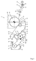
- the single figure of the drawing shows a schematic representation of an exemplary embodiment of an apparatus 10 for producing a fibrous web, which in the present case is, for example, a tissue web 22.
- a headbox 12 delivers a stock suspension jet into an inlet gap 14, which in the region of a forming roller 16 between an inner circumferential permeable structured band 18 and an outer circumferential Formierieb 20 is formed, which converge in the region of the forming roller 16 and are then performed together around this forming roller 16.
- the structural band 18 may in particular be a three-dimensionally structured sieve.
- the Formiersieb 20 has the tissue web 22 facing a relatively smooth compared to the respective side of the structural band 18 side.
- tissue web 22 facing side of the structural band 18 has recessed areas and relatively elevated areas, wherein the tissue web 22 is formed in these recessed and raised areas of the structural band 18.
- the structural band 18 may be formed, for example, by a TAD screen.
- the tissue web 22 is substantially dewatered by the outer forming wire 20. Subsequently, the forming fabric 20 in the region of a deflection roller 24 is again separated from the tissue web 22, which is guided together with the structure band 18 on to a pressing zone 26, in which the tissue web 22 between the structural band 18 and a circumferential, non-structured permeable support band 28 lying is pressed.
- the permeable support belt 28 may in particular be a felt.
- pressure is exerted on the structure band 18, the tissue web 22 and the support band 28 in such a way that the tissue web 22 is dewatered in the direction of the support band 28 formed, for example, by a felt.
- the tissue web 22 in the press zone 26 is dewatered in the direction of the permeable support belt 28, and the structural band passed through this press zone 26 in the present embodiment is identical to the structural belt on which the tissue web 22 has been formed, the bulky portions of the tissue web 22 become less strongly compressed than the less voluminous sections, so that as a result the voluminous structure of the voluminous sections concerned is retained.
- the dewatering pressure for the tissue web 22 in the press zone 26 is generated at least in sections simultaneously by a gas flow and by a mechanical pressing force.
- the gas stream first flows through the structure band 18, then the tissue web 22 and finally the permeable support band 28.
- the gas flow in the present case is generated by a suction zone 30 of a suction roll 32.
- the alternative and additionally applied mechanical force is produced by guiding the structure band 18, the tissue web 22 and the support band 28 in the press zone 26 between a tensioned press belt 34 and a smooth surface, which is formed here by the roller 32, for example ,
- the pressing zone 26 is at least substantially defined by the wrap area of the press belt 34 around the lateral surface of the suction roll 32, wherein this wrap is determined by the distance between the two guide rollers 36, 38.
- the tissue web 22, together with the structural band 18, is first guided via a suction box 40 and then through a press nip 44 formed on a drying cylinder, namely a Yankee cylinder 42.
- a press nip 44 formed on a drying cylinder, namely a Yankee cylinder 42.
- the press nip 44 is formed in the present case by a shoe press nip.
- the Yankee cylinder 42 is thus assigned a shoe press unit, here a shoe press roll 46, for forming the press nip 44.
- a hood 62 can be assigned to the Yankee cylinder 42.
- the tissue web 22 formed between the structural band 18 and the relatively smooth forming fabric 20 Because the tissue web has been formed between the structural band 18 and the relatively smooth forming fabric 20, only the side of the tissue web 22 formed on the structure band 18 has a wavy surface. In contrast, the surface of the tissue web 22 formed on the smooth forming fabric 20 is relatively smooth. With this smooth side, the tissue web 22 in the press nip 44 now comes into contact with the surface of the Yankee cylinder 42. The tissue web 22 thus touches the Yankee cylinder with a relatively large area.
- the structured strip 18 guided by the press nip 44 in the present exemplary embodiment is identical to the structure strip on which the tissue web 22 has been formed, it is also ensured that the voluminous regions of the tissue web 22 are practically not pressed in this press nip 44 either. In contrast, the less bulky areas of the tissue web 22 are pressed, whereby the strength of the tissue web 22 is further increased.
- the structure band 18 is separated from the tissue web 22, while the tissue web 22 on the Yankee cylinder 42 is guided to a scraper 48, whereby the tissue web 22 is creped and lifted off the Yankee cylinder 42.
- tissue web 22 is then fed to a calender 64 and subsequently to a reeling or unwinding device 50 in which it is wound up into a reel 54 with the aid of a pressure roller 52.
- the tissue web 22 is therefore transferred in the region of the press nip 44 from the structure band 18 onto the surface of the Yankee cylinder 42.
- the surface of the Yankee cylinder 42 is scraped off continuously, for example by means of the scraper 48, and subsequently coated again by means of a coating device 56, so that a new coating is always present in the press nip 44.
- a coating device 56 Via another scraper 70, the surface of the Yankee cylinder 42 is cleaned.
- the calender 64 comprises a calender nip 66 formed between two hard rolls 64 ', 64 "through which the fibrous web 22 passes, and the two calender rolls 66', 66" are not heated. They are each formed by a chill roll and uncoated.
- the calender 64 comprises only these two hard rollers 64 ', 64 ".
- the line load generated in the calendering nip 66 is preferably ⁇ 10 kN / m.
- the tissue web 22 is fed to the take-up device 50, which comprises a winding core 68 and a pressure roller 52 which can be applied or pressed against the winding 54 forming on the winding core 68.
- the line force in the winding nip between the pressure roller 52 and the winding 54 is preferably selected to be ⁇ 0.2 kN / m.
- the winding core 68 is driven in the present embodiment.
- the gas flow can also be generated at least partially by means of an overpressure hood or steam blower box 58 arranged on the side of the permeable structure strip 18.
- a three-dimensionally structured sieve for example a TAD sieve, can be used in particular as a structural band 18.
- a drainage band can be provided.
- the relatively recessed regions and the relatively elevated regions of the structure band 18 are preferably designed and arranged relative to one another such that a maximum of 35% and preferably not more than 25% of the structural band 18 is pressed in the press nip 44 formed with the Yankee cylinder 42.
Landscapes
- Paper (AREA)
- Sanitary Thin Papers (AREA)
- Treatment Of Fiber Materials (AREA)
Abstract
Description
- Die Erfindung betrifft eine Vorrichtung zur Herstellung einer Faserstoffbahn, insbesondere Tissuebahn. Des weiteren betrifft die Erfindung ein Verfahren zur Herstellung einer Tissuebahn. Bei dem betreffenden Tissuepapier kann es sich insbesondere um Hygienepapier wie bspw. Toilettenpapier oder Gesichtstuch handeln.
- Toiletten und Gesichsttuchpapier besitzt idealerweise eine hohe Weichheit, sog. "structural softness", eine hohe Weichheit der Oberfläche, sog. "surface softness" in Verbindung mit einer hohen Reißfestigkeit. Dabei wird die Weichheit wesentlich durch das Volumen und die Porosität des Tissuepapiers bestimmt.
- Zur Erhöhung des Volumens wurde bereits vorgeschlagen, die Tissuepapierbahn bei deren Herstellung nur zonal zu pressen, um neben den gepressten reißfesteren Bereichen auch lediglich leicht gepresste oder ungepresste voluminösere Bereiche zu erhalten.
- Bei der Herstellung von Tissuepapier wird die Tissuebahn in einem letzten Trocknungsschritt über die Mantelfläche eines beheizten Yankee-Trockenzylinders geführt, bevor das fertige Produkt von diesem gekreppt wird. Wird diese Tissuebahn über den Yankee-Trockenzylinder geführt wird, wird sie von einer Bespannung gehalten.
- Der Erfindung liegt die Aufgabe zugrunde, eine verbesserte Vorrichtung der ei n-gangs genannten Art zu schaffen. Dabei soll mit der betreffenden Vorrichtung insbesondere die Möglichkeit geschaffen werden, Tissuepapier sehr hohen Volumens mit einer hohen Weichheit zu erzeugen. Zudem soll das Tissuepapier mit einer möglichst weichen Oberfläche erzeugt werden, ohne dabei Einbußen hinsichtlich der anderen Eigenschaften des Tissuepapiers in Kauf nehmen zu müssen.
- Diese Aufgabe wird erfindungsgemäß gelöst durch eine Vorrichtung zur Herstellung einer Faserstoffbahn, insbesondere Tissuebahn, mit einer Presszone, durch die die Faserstoffbahn zusammen mit einem umlaufenden permeablen strukturierten Band und einem nicht strukturierten, d.h. glatten, permeablen Stützband zwischen Strukturband und Stützband liegend hindurchgeführt wird, und einem an einem Trockenzylinder vorgesehenen Pressnip, durch den die Faserstoffbahn zusammen mit dem Strukturband zwischen Strukturband und Trockenzylinder liegend hindurchgeführt wird, wobei die Faserstoffbahn im Anschluss an den Trockenzylinder durch einen Kalander geführt ist.
- Dem am Trockenzylinder vorgesehenen Pressnip kommt hierbei insbesondere im wesentlichen die Aufgabe des Transfers der Faserstoffbahn vom Strukturband auf den Trockenzylinder zu.
- Bei der Entwässerung der zwischen dem permeablen strukturierten Band und dem nicht strukturierten permeablen Stützband geführten Faserstoffbahn wird diese vorzugsweise in Richtung des Stützbandes entwässert.
- Der Kalander umfasst vorzugsweise einen zwischen zwei Hartwalzen gebildeten Kalandernip, durch den die Faserstoffbahn hindurchgeführt ist. Bevorzugt sind die beiden Kalanderwalzen nicht beheizt.
- Aufgrund dieser Ausbildung ergibt sich Tissuepapier sehr hohen Volumens mit entsprechend großem Weichheit. Durch den Einsatz eines entsprechenden Kalanders im Anschluss an den Trockenzylinder wird eine weiche Oberfläche des Tissuepapiers erreicht, während die anderen Eigenschaften des Tissuepapiers aufrechterhalten werden. Zudem erhält das Tissuepapier die gewünschte Griffigkeit.
- Bevorzugt sind die beiden Kalanderwalzen jeweils durch eine Hartgusswalze gebildet. Vorteilhafterweise sind die beiden Walzen jeweils unbeschichtet.
- Bei einer zweckmäßigen praktischen Ausführungsform der erfindungsgemäßen Vorrichtung umfasst der Kalander nur zwei Walzen.
- Zwischen den beiden Kalanderwalzen wird ein kleiner offener Kalandernip bzw. ein Kalandernip mit geringer Niplast gebildet. Dabei ist die in dem Kalandernip erzeugte Linienlast bevorzugt < 10 kN/m.
- In Anschluss an den Kalander ist die Faserstoffbahn zweckmäßigerweise einer Aufwickeleinrichtung zugeführt, die zweckmäßigerweise einen Wickelkern und eine Anpresswalze umfasst, die an den sich auf den Wickelkern bildenden Wickel anlegbar bzw. anpressbar ist.
- Um sicherzustellen, dass das zuvor erreichte hohe Volumen der Tissuebahn erhalten bleibt, ist die Linienkraft in dem Wickelspalt zwischen Anpresswalze und Wickel vorzugsweise ≤ 0,2 kN/m. Demgegenüber ist bei den bisher üblichen Aufwickeleinrichtungen diese Linienkraft in der Regel > 0,8 kN/m.
- Zweckmäßigerweise ist der Wickelkern der Aufwickeleinrichtung angetrieben. Alternativ oder zusätzlich kann jedoch auch die Anpresswalze angetrieben sein.
- Da im Fall eines angetriebenen Wickelkerns der sich bildende Wickel nicht von der Anpresswalze mitgenommen werden muss, sind die gewünschten möglichst kleinen Linienkräfte im Wickelspalt problemlos realisierbar. Die gewünschten möglichst geringen Linienkräfte sind jedoch auch im Fall einer angetriebenen Anpresswalze möglich, da die Faserstoffbahn in einem solchen Fall beispielsweise mittels eines Siebbandes ausgehend vom Schaber dem Wickelspalt zugeführt werden kann, so dass auch hier kein Zug erforderlich ist.
- Nachdem die Faserstoffbahn in der Presszone zwischen dem Strukturband und einem umlaufenden, nicht strukturierten, d.h. relativ glatten permeablen Stützband liegend gepresst wird, kann die Tissuebahn mit einer relativ glatten Seite mit dem bevorzugt als Yankee-Zylinder ausgeführten Trockenzylinder in Kontakt gebracht werden, während andererseits aufgrund des auf der anderen Bahnseite liegenden Strukturbandes lediglich ein Teil der Faserstoff- bzw. Tissuebahn gepresst wird. Anders als bei den herkömmlichen TAD-Maschinen kann die Tissuebahn also mit annähernd 100 % Oberfläche der betreffenden Seite mit dem Yankee-Zylinder in Kontakt kommen, während nur ein Teil davon gepresst wird.
- Bevorzugt wird die Faserstoffbahn in einer Blattbildungszone auf dem Strukturband gebildet. Damit werden die Vertiefungen des strukturierten Bandes mit Fasern aufgefüllt, anstatt die Fasern einer bereits gebildeten Bahn wie bei einem herkömmlichen TAD-Verfahren in die Vertiefungen des Strukturbandes zu saugen.
- Indem die Faserstoffbahn zur vom Strukturband abgewandten Seite hin durch das Stütz- und/oder Entwässerungsband hin weiter entwässert wird, werden die Fasern in Richtung der relativ ebenen oder glatten Oberfläche des insbesondere durch ein Entwässerungsband gebildeten Stützbandes gedrängt. Die Entwässerung kann beispielsweise durch ein entsprechend hohes Vakuum und/oder mechanisch, beispielsweise mittels eines Spannbandes erfolgen, durch das das Strukturband, die Faserstoffbahn und das Stützband gegen eine vorzugsweise glatte Fläche gepresst werden. Der betreffende Gasstrom durchströmt bevorzugt also zunächst das permeable Strukturband, dann die Faserstoffbahn und anschließend das vorzugsweise permeable Stützband. Demgegenüber durchströmt bei einem herkömmlichen TAD-Verfahren der betreffende Gasstrom zunächst die Faserstoffbahn und dann das Strukturband. Anders als bei der erfindungsgemäßen Lösung erhält die Faserstoffbahn bei einem solchen herkömmlichen TAD-Verfahren also keine glatte Fläche. Abgesehen davon ist der beim herkömmlichen TAD-Verfahren erzeugte Differenzdruck relativ gering.
- Vorteilhafterweise ist die Presszone auf der dem Stützband benachbarten Seite durch eine zumindest im Wesentlichen glatte Oberfläche begrenzt.
- Bei einer zweckmäßigen praktischen Ausführungsform der erfindungsgemäßen Vorrichtung ist die die Presszone auf der dem Stützband benachbarten Seite begrenzende vorzugsweise glatte Oberfläche durch eine gekrümmte Oberfläche gebildet. Dabei ist diese gekrümmte Oberfläche bevorzugt durch eine rotierende Walze gebildet.
- Von Vorteil ist insbesondere auch, wenn Mittel zur Erzeugung eines Gasstromes im Bereich der Presszone vorgesehen sind, der das Strukturband, die Faserstoffbahn und das Stützband durchströmt. Dabei durchströmt der Gasstrom bevorzugt zunächst das Strukturband, dann die Faserstoffbahn und schließlich das Stützband.
- Es können insbesondere Mittel zur Erzeugung eines Luftstromes und/oder Mittel zur Erzeugung eines Dampfstromes vorgesehen sein.
- Gemäß einer vorteilhaften praktischen Ausführungsform der Vorrichtung umfassen die Mittel zur Erzeugung eines Gasstromes eine mit einer Saugzone versehene rotierende Saugwalze, die die Presszone auf der dem Stützband benachbarten Seite begrenzt. Die gekrümmte, vorzugsweise glatte Fläche ist in diesem Fall also durch die rotierende Saugwalze gebildet.
- Grundsätzlich kann der Gasstrom zumindest teilweise aber auch mittels eines ebenen oder gekrümmten Saugkastens oder dergleichen erzeugt werden, der die Presszone auf der dem Stützband benachbarten Seite begrenzt.
- Darüber hinaus ist beispielsweise auch denkbar, den Gasstrom zumindest teilweise mittels einer auf der Seite des permeablen Strukturbandes angeordneten Überdruckhaube zu erzeugen.
- Alternativ oder zusätzlich können das Strukturband, die Faserstoffbahn und das Stützband vorteilhafterweise mittels eines unter Spannung stehenden Pressbandes gegen die vorzugsweise glatte Oberfläche gepresst werden. Dabei kann die vorzugsweise glatte Oberfläche insbesondere wieder durch eine rotierende Walze gebildet sein.
- Als Strukturband ist zweckmäßigerweise ein strukturiertes Sieb vorgesehen.
- Gemäß einer bevorzugten praktischen Ausführungsform der erfindungsgemäßen Vorrichtung ist als Strukturband ein TAD-(Through-Air-Drying)-Sieb vorgesehen.
- Bei dem Stützband kann es sich, wie bereits erwähnt, insbesondere um ein Entwässerungsband, vorzugsweise einen Filz handeln.
- Bevorzugt sind die relativ vertieften und die relativ erhöhten Bereiche des Strukturbandes derart ausgebildet und relativ zueinander angeordnet, dass maximal 35 % und vorzugsweise maximal 25 % des Strukturbandes im Pressnip gepresst werden.
- Eine möglichst schonende Pressung wird dadurch erreicht, dass der an dem Trocken- bzw. Yankee-Zylinder vorgesehene Pressnip ein Schuhpressnip ist.
- Wie bereits erwähnt, wird die Faserstoffbahn im Bereich des Pressnips vorzugsweise von dem Strukturband auf die Oberfläche des Trocken- bzw. Yankee-Zylinders übertragen. In diesem Pressnip liegt die Faserstoffbahn also zwischen dem Strukturband und dem Trockenzylinder, d.h. auf der Seite des Trockenzylinders.
- Die vom Trocken- bzw. Yankee-Zylinder wieder abgenommene Faserstoffbahn wird dann, wie bereits erwähnt, der Aufwickeleinrichtung zugeführt.
- Bei dem erfindungsgemäßen Verfahren zur Herstellung einer Tissuepapierbahn insbesondere Hygienepapierbahn werden folgende Schritte ausgeführt:
- Pressen der zwischen einem permeablen strukturierten Band und einem nicht strukturierten permeablen Stützband geführten Tissuepapierbahn,
- nachfolgendes Trocknen der Tissuepapierbahn an einer beheizten Fläche und
- nachfolgend Kalandrieren der Tissuepapierbahn.
- Vorzugsweise wird mit dem erfindungsgemäßen Verfahren Hygienepapier, wie bspw. Toilettenpapier, Kosmetikpapier oder Papiertaschentuchpapier hergestellt.
- Die Erfindung wird im Folgenden anhand eines Ausführungsbeispiels unter Bezugnahme auf die Zeichnung näher erläutert.
- Die einzige Figur der Zeichnung zeigt in schematischer Darstellung eine beispielhafte Ausführungsform einer Vorrichtung 10 zur Herstellung einer Faserstoffbahn, bei der es sich im vorliegenden Fall beispielsweise um eine Tissuebahn 22 handelt.
- Ein Stoffauflauf 12 liefert einen Stoffsuspensionsstrahl in einen Einlaufspalt 14, der im Bereich einer Formierwalze 16 zwischen einem innenliegenden umlaufenden permeablen strukturierten Band 18 und einem außenliegenden umlaufenden Formiersieb 20 gebildet ist, die im Bereich der Formierwalze 16 zusammenlaufen und anschließend gemeinsam um diese Formierwalze 16 geführt sind.
- Bei dem Strukturband 18 kann es sich insbesondere um ein dreidimensional strukturiertes Sieb handeln.
- Das Formiersieb 20 weist der Tissuebahn 22 zugewandt eine im Vergleich zur betreffenden Seite des Strukturbandes 18 relativ glatte Seite auf.
- Demgegenüber besitzt die der Tissuebahn 22 zugewandte Seite des Strukturbandes 18 vertiefte Bereiche und relativ dazu erhöhte Bereiche, wobei die Tissuebahn 22 in diesen vertieften und erhöhten Bereichen des Strukturbandes 18 gebildet wird.
- Das Strukturband 18 kann beispielsweise durch ein TAD-Sieb gebildet sein.
- Im Bereich der Formierwalze 16 wird die Tissuebahn 22 im Wesentlichen durch das außenliegende Formiersieb 20 entwässert. Anschließend wird das Formiersieb 20 im Bereich einer Umlenkwalze 24 wieder von der Tissuebahn 22 getrennt, die zusammen mit dem Strukturband 18 weiter zu einer Presszone 26 geführt wird, in der die Tissuebahn 22 zwischen dem Strukturband 18 und einem umlaufenden, nicht strukturierten permeablen Stützband 28 liegend gepresst wird.
- Bei dem permeablen Stützband 28 kann es sich insbesondere um einen Filz handeln. Im Bereich der Presszone 26 wird derart Druck auf das Strukturband 18, die Tissuebahn 22 und das Stützband 28 ausgeübt, dass die Tissuebahn 22 in Richtung des beispielsweise durch einen Filz gebildeten Stützbandes 28 entwässert wird.
- Da die Tissuebahn 22 in der Presszone 26 in Richtung des permeablen Stützbandes 28 entwässert wird und das mit durch diese Presszone 26 geführte Strukturband beim vorliegenden Ausführungsbeispiel identisch mit dem Strukturband ist, auf dem die Tissuebahn 22 gebildet wurde, werden die voluminöseren Abschnitte der Tissuebahn 22 weniger stark komprimiert als die weniger voluminösen Abschnitte, so dass im Ergebnis die voluminöse Struktur der betreffenden voluminöseren Abschnitte erhalten bleibt.
- Im vorliegenden Fall wird der Entwässerungsdruck für die Tissuebahn 22 in der Presszone 26 zumindest abschnittsweise gleichzeitig durch einen Gasstrom und durch eine mechanische Presskraft erzeugt.
- Der Gasstrom durchströmt zunächst das Strukturband 18, dann die Tissuebahn 22 und schließlich das permeable Stützband 28.
- Wie anhand der Figur 1 zu erkennen ist, wird die Gasströmung im vorliegenden Fall durch eine Saugzone 30 einer Saugwalze 32 erzeugt.
- Die alternative und zusätzlich aufgebrachte mechanische Kraft wird dadurch erzeugt, dass das Strukturband 18, die Tissuebahn 22 und das Stützband 28 in der Presszone 26 zwischen einem unter Spannung stehenden Pressband 34 und einer glatten Oberfläche geführt wird, die hier beispielsweise durch die Walze 32 gebildet wird.
- Die Presszone 26 ist zumindest im Wesentlichen durch den Umschlingungsbereich des Pressbandes 34 um die Mantelfläche der Saugwalze 32 festgelegt, wobei dieser Umschlingungsbereich durch den Abstand der beiden Umlenkwalzen 36, 38 festgelegt ist.
- Im Anschluss an die Saugwalze 32 wird die Tissuebahn 22 zusammen mit dem Strukturband 18 zunächst über einen Saugkasten 40 und daraufhin durch einen an einem Trockenzylinder, nämlich einem Yankee-Zylinder 42 gebildeten Pressnip 44 geführt. Dabei liegt die Tissuebahn 22 in diesem Pressnip 44 zwischen dem Strukturband 18 und der glatten Oberfläche des Yankee-Zylinders 42. Der Pressnip 44 ist im vorliegenden Fall durch einen Schuhpressnip gebildet. Dem Yankee-Zylinder 42 ist zur Bildung des Pressnips 44 also eine Schuhpresseinheit, hier eine Schuhpresswalze 46 zugeordnet. Wie anhand der Figur 1 zu erkennen ist, kann dem Yankee-Zylinder 42 eine Haube 62 zugeordnet sein.
- Dadurch, dass die Tissuebahn zwischen dem Strukturband 18 und dem dazu relativ glatten Formiersieb 20 gebildet wurde, weist nur die auf dem Strukturband 18 gebildete Seite der Tissuebahn 22 eine wellige Oberfläche auf. Demgegenüber ist die auf dem glatten Formiersieb 20 gebildete Oberfläche der Tissuebahn 22 relativ glatt. Mit dieser glatten Seite kommt die Tissuebahn 22 im Pressnip 44 nun in Kontakt mit der Oberfläche des Yankee-Zylinders 42. Die Tissuebahn 22 berührt den Yankee-Zylinder also mit einer relativ großen Fläche. Nachdem das durch den Pressnip 44 geführte Strukturband 18 beim vorliegenden Ausführungsbeispiel identisch ist mit dem Strukturband, auf dem die Tissuebahn 22 gebildet wurde, ist überdies sichergestellt, dass die voluminöseren Bereiche der Tissuebahn 22 auch in diesem Pressnip 44 praktisch nicht gepresst werden. Dagegen werden die weniger voluminösen Bereiche der Tissuebahn 22 gepresst, wodurch die Festigkeit der Tissuebahn 22 weiter erhöht wird.
- Im Anschluss an den Pressnip 44 wird das Strukturband 18 von der Tissuebahn 22 getrennt, während die Tissuebahn 22 auf dem Yankee-Zylinder 42 bis zu einem Schaber 48 geführt wird, wodurch die Tissuebahn 22 gekreppt und vom Yankee-Zylinder 42 abgehoben wird.
- Daraufhin wird die Tissuebahn 22 einem Kalander 64 und im Anschluss daran einer Aufroll- oder Abwickeleinrichtung 50 zugeführt, in der sie mit Hilfe einer Anpresswalze 52 zu einem Wickel 54 aufgewickelt wird.
- Die Tissuebahn 22 wird also im Bereich des Pressnips 44 von dem Strukturband 18 auf die Oberfläche des Yankee-Zylinders 42 übertragen. Dabei wird die Oberfläche des Yankee-Zylinders 42 beispielsweise mittels des Schabers 48 laufend abgeschabt und mittels einer Beschichtungseinrichtung 56 anschließend wieder neu beschichtet, so dass in Pressnip 44 stets eine erneute Beschichtung vorliegt. Über einen weiteren Schaber 70 wird die Oberfläche des Yankee-Zylinders 42 gereinigt.
- Der Kalander 64 umfasst einen zwischen zwei Hartwalzen 64', 64" gebildeten Kalandernip 66, durch den die Faserstoffbahn 22 hindurchgeführt wird. Die beiden Kalanderwalzen 66', 66" sind nicht beheizt. Sie sind jeweils durch eine Hartgusswalze gebildet und unbeschichtet.
- Wie anhand der Figur 1 zu erkennen ist, umfasst der Kalander 64 nur diese beiden Hartwalzen 64', 64".
- Die in dem Kalandernip 66 erzeugte Linienlast ist bevorzugt < 10 kN/m.
- Im Anschluss an den Kalander 64 wird die Tissuebahn 22 der Aufwickeleinrichtung 50 zugeführt, die einen Wickelkern 68 und eine Anpresswalze 52 umfasst, die an den sich auf dem Wickelkern 68 bildenden Wickel 54 anlegbar bzw. anpressbar ist. Um das zuvor erreichte relativ hohe Volumen der Tissuebahn 22 aufrechtzuerhalten, wird die Linienkraft in dem Wickelspalt zwischen Anpresswalze 52 und Wickel 54 bevorzugt ≤ 0,2 kN/m gewählt.
- Wie anhand der Figur 1 zu erkennen ist, ist beim vorliegenden Ausführungsbeispiel der Wickelkern 68 angetrieben.
- Als Gasstrom, der in der Presszone 26 zunächst das Strukturband 18, dann die Tissuebahn 22 und schließlich das Stützband 28 durchströmt kann, insbesondere ein Luftstrom und/oder Dampfstrom erzeugt werden.
- Alternativ oder zusätzlich zur Saugwalze 32 kann der Gasstrom zumindest teilweise auch mittels einer auf der Seite des permeablen Strukturbandes 18 angeordneten Überdruckhaube oder Dampfblaskastens 58 erzeugt werden.
- Wie bereits erwähnt, kann als Strukturband 18 insbesondere ein dreidimensional strukturiertes Sieb, beispielsweise ein TAD-Sieb eingesetzt werden.
- Als Stützband 28 kann, wie bereits erwähnt, insbesondere ein Entwässerungsband vorgesehen sein.
- Die relativ vertieften und die relativ erhöhten Bereiche des Strukturbandes 18 sind bevorzugt so ausgebildet und relativ zueinander angeordnet, dass maximal 35 % und vorzugsweise maximal 25 % des Strukturbandes 18 im mit dem Yankee-Zylinder 42 gebildeten Pressnip 44 gepresst werden.
-
- 10
- Vorrichtung
- 12
- Stoffauflauf
- 14
- Einlaufspalt
- 16
- Formierwalze
- 18
- Strukturband
- 20
- Formiersieb
- 22
- Tissuebahn
- 24
- Umlenkwalze
- 26
- Presszone
- 28
- Stützband
- 30
- Saugzone
- 34
- Pressband
- 36
- Umlenkwalze
- 38
- Umlenkwalze
- 40
- Saugkasten
- 42
- Yankee-Zylinder
- 44
- Pressnip
- 46
- Schuhpresswalze
- 48
- Schaber
- 50
- Aufwickeleinrichtung
- 52
- Anpresswalze
- 54
- Wickel
- 56
- Beschichtungseinrichtung
- 58
- Überdruckhaube, Dampfblaskasten
- 62
- Haube
- 64
- Kalander
- 64'
- Kalanderwalze, Hartwalze
- 64"
- Kalanderwalze, Hartwalze
- 66
- Kalandernip
- 68
- Wickelkern
- 70
- Schaber
Claims (34)
- Vorrichtung (10) zur Herstellung einer Faserstoffbahn (22), insbesondere Tissuebahn, mit einer Presszone (26), durch die die Faserstoffbahn (22) zusammen mit einem umlaufenden permeablen strukturierten Band (18) und einem nicht strukturierten permeablen Stützband (28) zwischen Strukturband (18) und Stützband (28) liegend hindurchgeführt wird, und einem an einem Trockenzylinder (42) vorgesehenen Pressnip (44), durch den die Faserstoffbahn (22) zusammen mit dem Strukturband (18) zwischen Strukturband (18) und Trockenzylinder (42) liegend hindurchgeführt wird, wobei die Faserstoffbahn im Anschluss an den Trockenzylinder (42) durch einen Kalander (64) geführt ist.
- Vorrichtung nach Anspruch 1,
dadurch gekennzeichnet,
dass der Kalander (64) einen zwischen zwei Hartwalzen (64', 64") gebildeten Kalandernip (66) umfasst, durch den die Faserstoffbahn (22) hindurchgeführt ist. - Vorrichtung nach Anspruch 2,
dadurch gekennzeichnet,
dass die beiden Kalanderwalzen (64', 64") nicht beheizt sind. - Vorrichtung nach Anspruch 2 oder 3,
dadurch gekennzeichnet,
dass die beiden Kalanderwalzen (64', 64") jeweils durch eine Hartgusswalze gebildet sind. - Vorrichtung nach einem der vorhergehenden Ansprüche,
dadurch gekennzeichnet,
dass die beiden Kalanderwalzen (64', 64") jeweils unbeschichtet sind. - Vorrichtung nach einem der vorhergehenden Ansprüche,
dadurch gekennzeichnet,
dass der Kalander (64) nur zwei Walzen (64', 64") umfasst. - Vorrichtung nach einem der vorhergehenden Ansprüche,
dadurch gekennzeichnet,
dass die in dem Kalandernip (66) erzeugte Linienlast < 10 kN/m ist. - Vorrichtung nach einem der vorhergehenden Ansprüche,
dadurch gekennzeichnet,
dass die Faserstoffbahn (22) im Anschluss an den Kalander (64) einer Aufwickeleinrichtung (50) zugeführt ist. - Vorrichtung nach Anspruch 8,
dadurch gekennzeichnet,
dass die Aufwickeleinrichtung (50) einen Wickelkern (68) und eine Anpresswalze (52) umfasst, die an den sich auf dem Wickelkern (68) bildenden Wickel (54) anlegbar ist. - Vorrichtung nach Anspruch 9,
dadurch gekennzeichnet,
dass die Linienkraft in dem Wickelspalt zwischen Anpresswalze (52) und Wickel (54) ≤ 0,2 kN/m ist. - Vorrichtung nach einem der vorhergehenden Ansprüche,
dadurch gekennzeichnet,
dass der Wickelkern (68) angetrieben ist. - Vorrichtung nach einem der vorhergehenden Ansprüche,
dadurch gekennzeichnet,
dass die Anpresswalze (52) angetrieben ist. - Vorrichtung nach einem der vorhergehenden Ansprüche,
dadurch gekennzeichnet,
dass die Faserstoffbahn (22) der Aufwickeleinrichtung (50) mittels eines Siebbandes zugeführt ist. - Vorrichtung nach einem der vorhergehenden Ansprüche,
dadurch gekennzeichnet,
dass die Faserstoffbahn (22) in einer Blattbildungszone auf dem Strukturband (22) gebildet wird. - Vorrichtung nach einem der vorhergehenden Ansprüche,
dadurch gekennzeichnet,
dass der Trockenzylinder durch einen Yankee-Zylinder (42) gebildet ist. - Vorrichtung nach einem der vorhergehenden Ansprüche,
dadurch gekennzeichnet,
dass die Presszone (26) auf der dem Stützband (28) benachbarten Seite durch eine zumindest im Wesentlichen glatte Oberfläche begrenzt ist. - Vorrichtung nach einem der vorhergehenden Ansprüche,
dadurch gekennzeichnet,
dass die die Presszone (26) auf der dem Stützband (28) benachbarten Seite begrenzende vorzugsweise glatte Oberfläche durch eine gekrümmte Oberfläche gebildet ist. - Vorrichtung nach Anspruch 17,
dadurch gekennzeichnet,
dass die die Presszone (26) auf der dem Stützband (28) benachbarten Seite begrenzende gekrümmte Oberfläche durch eine rotierende Walze (32) gebildet ist. - Vorrichtung nach einem der vorhergehenden Ansprüche,
dadurch gekennzeichnet,
dass Mittel (30, 32) zur Erzeugung eines Gasstromes im Bereich der Presszone (26) vorgesehen sind, der das Strukturband (18), die Faserstoffbahn (22) und das Stützband (28) durchströmt. - Vorrichtung nach Anspruch 19,
dadurch gekennzeichnet,
dass der Gasstrom zunächst das Strukturband (18), dann die Faserstoffbahn (22) und schließlich das Stützband (28) durchströmt. - Vorrichtung nach Anspruch 19 oder 20,
dadurch gekennzeichnet,
dass Mittel (30, 32) zur Erzeugung eines Luftstromes und/oder Mittel zur Erzeugung eines Dampfstromes vorgesehen sind. - Vorrichtung nach einem der Ansprüche 19 bis 21,
dadurch gekennzeichnet,
dass die Mittel zur Erzeugung eines Gasstromes eine mit einer Saugzone (30) versehene rotierende Saugwalze (32) umfassen, die die Presszone (26) auf der dem Stützband (28) benachbarten Seite begrenzt. - Vorrichtung nach einem der Ansprüche 19 bis 21,
dadurch gekennzeichnet,
dass die Mittel zur Erzeugung eines Gasstromes einen ebenen oder gekrümmten Saugkasten umfassen, der die Presszone (26) auf der dem Stützband (28) benachbarten Seite begrenzt. - Vorrichtung nach einem der Ansprüche 19 bis 23,
dadurch gekennzeichnet,
dass die Mittel zur Erzeugung eines Gasstromes eine auf der Seite des permeablen Strukturbandes (18) angeordnete Überdruckhaube (58) umfassen. - Vorrichtung nach einem der vorhergehenden Ansprüche,
dadurch gekennzeichnet,
dass das Strukturband (18), die Faserstoffbahn (22) und das Stützband (28) mittels eines unter Spannung stehenden Pressbandes (34) gegen die vorzugsweise glatte Oberfläche pressbar sind. - Vorrichtung nach Anspruch 25,
dadurch gekennzeichnet,
dass die vorzugsweise glatte, gekrümmte Oberfläche durch eine rotierende Walze (32) gebildet ist. - Vorrichtung nach einem der vorhergehenden Ansprüche,
dadurch gekennzeichnet,
dass als Strukturband (18) ein strukturiertes Sieb vorgesehen ist. - Vorrichtung nach einem der vorhergehenden Ansprüche,
dadurch gekennzeichnet,
dass als Strukturband (18) ein TAD-Sieb vorgesehen ist. - Vorrichtung nach einem der vorhergehenden Ansprüche,
dadurch gekennzeichnet,
dass als Stützband (28) ein Entwässerungsband, insbesondere Filz, vorgesehen ist. - Vorrichtung nach einem der vorhergehenden Ansprüche,
dadurch gekennzeichnet,
dass die relativ vertieften und die relativ erhöhten Bereich des Strukturbandes (18) derart ausgebildet und relativ zueinander angeordnet sind, dass maximal 35 % und vorzugsweise maximal 25 % des Strukturbandes (18) im Pressnip (44) gepresst werden. - Vorrichtung nach einem der vorhergehenden Ansprüche,
dadurch gekennzeichnet,
dass der am Trockenzylinder (42) vorgesehene Pressnip (44) durch einen Schuhpressnip gebildet ist. - Vorrichtung nach einem der vorhergehenden Ansprüche,
dadurch gekennzeichnet,
dass die Faserstoffbahn (22) im Bereich des Pressnips (44) von dem Strukturband (18) auf die Oberfläche des Trockenzylinders (42) übertragen wird. - Verfahren zur Herstellung einer Tissuebahn (22), insbesondere Hygienepapierbahn, mit folgenden Schritten:- Pressen der zwischen einem permeablen strukturierten Band (18) und einem nicht strukturierten permeablen Stützband (28) geführten Tissuebahn (22),- nachfolgendes Trocknen der Tissuebahn (22) an einer beheizten Fläche und- nachfolgend Kalandrieren der Tissuebahn (22).
- Hygienepapier, wie bspw. Toilettenpapier, Kosmetikpapier oder Papiertaschentuchpapier hergestellt mit dem Verfahren nach Anspruch 33.
Applications Claiming Priority (1)
| Application Number | Priority Date | Filing Date | Title |
|---|---|---|---|
| DE102005046907A DE102005046907A1 (de) | 2005-09-30 | 2005-09-30 | Verfahren und Vorrichtung zur Herstellung einer Tissuebahn |
Publications (2)
| Publication Number | Publication Date |
|---|---|
| EP1770210A1 true EP1770210A1 (de) | 2007-04-04 |
| EP1770210B1 EP1770210B1 (de) | 2011-12-21 |
Family
ID=37420832
Family Applications (1)
| Application Number | Title | Priority Date | Filing Date |
|---|---|---|---|
| EP06114195A Expired - Lifetime EP1770210B1 (de) | 2005-09-30 | 2006-05-19 | Verfahren und Vorrichtung zur Herstellung einer Tissuebahn |
Country Status (4)
| Country | Link |
|---|---|
| US (1) | US7691230B2 (de) |
| EP (1) | EP1770210B1 (de) |
| AT (1) | ATE538244T1 (de) |
| DE (1) | DE102005046907A1 (de) |
Cited By (1)
| Publication number | Priority date | Publication date | Assignee | Title |
|---|---|---|---|---|
| US20150129146A1 (en) * | 2013-11-14 | 2015-05-14 | Georgia-Pacific Consumer Products Lp | Soft, absorbent sheets having high absorbency and high caliper, and methods of making soft, absorbent sheets |
Families Citing this family (35)
| Publication number | Priority date | Publication date | Assignee | Title |
|---|---|---|---|---|
| DE10326304A1 (de) * | 2003-06-11 | 2005-02-03 | Voith Fabrics Patent Gmbh | Verfahren und Vorrichtung zur Herstellung einer Tissuebahn |
| DE102004052157A1 (de) * | 2004-10-26 | 2006-04-27 | Voith Fabrics Patent Gmbh | Maschine zur Herstellung einer Materialbahn |
| DE102005046903A1 (de) * | 2005-09-30 | 2007-04-05 | Voith Patent Gmbh | Verfahren und Vorrichtung zur Herstellung einer Tissuebahn |
| DE102005054510A1 (de) * | 2005-11-16 | 2007-05-24 | Voith Patent Gmbh | Tissuemaschine |
| AT505760B1 (de) * | 2008-01-09 | 2009-04-15 | Andritz Ag Maschf | Vorrichtung und verfahren zur entwasserung einer materialbahn |
| DE102008041951A1 (de) * | 2008-09-10 | 2010-03-11 | Voith Patent Gmbh | Verfahren zur Vorhersage der Oberflächentopographie von Tissuepapier |
| US8557085B1 (en) * | 2012-07-10 | 2013-10-15 | Pmt Italia S.P.A. | Dryer apparatus for drying a web |
| US8968517B2 (en) | 2012-08-03 | 2015-03-03 | First Quality Tissue, Llc | Soft through air dried tissue |
| JP6277654B2 (ja) * | 2013-10-03 | 2018-02-14 | セイコーエプソン株式会社 | シート製造装置 |
| WO2015176063A1 (en) | 2014-05-16 | 2015-11-19 | First Quality Tissue, Llc | Flushable wipe and method of forming the same |
| MX378630B (es) | 2014-11-12 | 2025-03-10 | First Quality Tissue Llc | Fibra de cannabis, estructuras celulosicas absorbentes que contienen fibra de cannabis y metodos para producir las mismas. |
| CA2968311C (en) | 2014-11-24 | 2023-11-21 | First Quality Tissue, Llc | Soft tissue produced using a structured fabric and energy efficient pressing |
| US9719213B2 (en) * | 2014-12-05 | 2017-08-01 | First Quality Tissue, Llc | Towel with quality wet scrubbing properties at relatively low basis weight and an apparatus and method for producing same |
| EP3221134B1 (de) | 2014-12-05 | 2026-05-20 | Structured I Llc | Herstellungsverfahren für papierherstellungsbänder unter verwendung einer 3d-druck-technologie |
| CN105735026B (zh) * | 2014-12-11 | 2019-08-09 | 福伊特专利有限公司 | 用于制造纤维材料腹板的机器 |
| FI127336B (fi) | 2014-12-17 | 2018-04-13 | Valmet Technologies Inc | Kiillotussylinterillä varustettu kuiturainakone |
| US10538882B2 (en) | 2015-10-13 | 2020-01-21 | Structured I, Llc | Disposable towel produced with large volume surface depressions |
| WO2017066465A1 (en) | 2015-10-13 | 2017-04-20 | First Quality Tissue, Llc | Disposable towel produced with large volume surface depressions |
| MX2018004622A (es) | 2015-10-14 | 2019-05-06 | First Quality Tissue Llc | Producto empaquetado y sistema y metodo para formar el mismo. |
| CN109154143A (zh) | 2016-02-11 | 2019-01-04 | 结构 I 有限责任公司 | 用于造纸机的包括聚合物层的带或织物 |
| US20170314206A1 (en) | 2016-04-27 | 2017-11-02 | First Quality Tissue, Llc | Soft, low lint, through air dried tissue and method of forming the same |
| CA3168412C (en) | 2016-08-26 | 2024-10-22 | Structured I, Llc | METHOD FOR PRODUCING ABSORBENT STRUCTURES EXHIBITING HIGH RESISTANCE IN THE WET STATE, HIGH ABSORPTION CAPACITY AND FLEXIBILITY |
| US10422078B2 (en) | 2016-09-12 | 2019-09-24 | Structured I, Llc | Former of water laid asset that utilizes a structured fabric as the outer wire |
| US11583489B2 (en) | 2016-11-18 | 2023-02-21 | First Quality Tissue, Llc | Flushable wipe and method of forming the same |
| US10619309B2 (en) | 2017-08-23 | 2020-04-14 | Structured I, Llc | Tissue product made using laser engraved structuring belt |
| DE102018114748A1 (de) | 2018-06-20 | 2019-12-24 | Voith Patent Gmbh | Laminierte Papiermaschinenbespannung |
| US11738927B2 (en) | 2018-06-21 | 2023-08-29 | First Quality Tissue, Llc | Bundled product and system and method for forming the same |
| US11697538B2 (en) | 2018-06-21 | 2023-07-11 | First Quality Tissue, Llc | Bundled product and system and method for forming the same |
| CA3131707A1 (en) | 2020-09-24 | 2022-03-24 | First Quality Tissue, Llc | Systems and methods for application of surface chemistry to bath tissue, facial tissue, and paper towel |
| EP4262498A4 (de) | 2020-12-17 | 2024-04-24 | First Quality Tissue, LLC | Nassgelegte wegwerf-absorptionsstrukturen mit hoher nassfestigkeit und verfahren zu ihrer herstellung |
| AU2023295030A1 (en) | 2022-06-16 | 2025-01-09 | First Quality Tissue, Llc | Wet laid paper and paperboard products with high wet strength and method of making the same |
| US11952721B2 (en) | 2022-06-16 | 2024-04-09 | First Quality Tissue, Llc | Wet laid disposable absorbent structures with high wet strength and method of making the same |
| US11976421B2 (en) | 2022-06-16 | 2024-05-07 | First Quality Tissue, Llc | Wet laid disposable absorbent structures with high wet strength and method of making the same |
| AU2023292707A1 (en) | 2022-06-16 | 2025-01-16 | First Quality Tissue, Llc | Wet laid paper and paperboard products with high wet strength and method of making the same |
| AT526668B1 (de) * | 2023-08-10 | 2024-06-15 | Andritz Ag Maschf | Maschine und verfahren zur herstellung einer faserstoffbahn |
Citations (5)
| Publication number | Priority date | Publication date | Assignee | Title |
|---|---|---|---|---|
| US4300981A (en) | 1979-11-13 | 1981-11-17 | The Procter & Gamble Company | Layered paper having a soft and smooth velutinous surface, and method of making such paper |
| US5779860A (en) * | 1996-12-17 | 1998-07-14 | Kimberly-Clark Worldwide, Inc. | High-density absorbent structure |
| US20020060036A1 (en) * | 2000-06-28 | 2002-05-23 | Metso Paper Karlstad Ab | Shortened layout from dryer to reel in tissue machine |
| US20050167066A1 (en) | 2004-01-30 | 2005-08-04 | Jeffrey Herman | Apparatus for and process of material web formation on a structured fabric in a paper machine |
| US20060167066A1 (en) | 2004-12-20 | 2006-07-27 | Genentech, Inc. | Pyrrolidine inhibitors of IAP |
Family Cites Families (9)
| Publication number | Priority date | Publication date | Assignee | Title |
|---|---|---|---|---|
| US4309246A (en) * | 1977-06-20 | 1982-01-05 | Crown Zellerbach Corporation | Papermaking apparatus and method |
| US5690788A (en) * | 1994-10-11 | 1997-11-25 | James River Corporation Of Virginia | Biaxially undulatory tissue and creping process using undulatory blade |
| US6187137B1 (en) * | 1997-10-31 | 2001-02-13 | Kimberly-Clark Worldwide, Inc. | Method of producing low density resilient webs |
| US6368458B1 (en) * | 1998-03-19 | 2002-04-09 | Voith Sulzer Paper Technology North America, Inc. | Calender press for a paper-making machine with thermally compensated top and bottom rolls and low nip load |
| US6183601B1 (en) * | 1999-02-03 | 2001-02-06 | Kimberly-Clark Worldwide, Inc. | Method of calendering a sheet material web carried by a fabric |
| US6610173B1 (en) * | 2000-11-03 | 2003-08-26 | Kimberly-Clark Worldwide, Inc. | Three-dimensional tissue and methods for making the same |
| US7297233B2 (en) * | 2004-01-30 | 2007-11-20 | Voith Paper Patent Gmbh | Dewatering apparatus in a paper machine |
| US20050167067A1 (en) * | 2004-01-30 | 2005-08-04 | Bob Crook | Dewatering fabric in a paper machine |
| US7351307B2 (en) * | 2004-01-30 | 2008-04-01 | Voith Paper Patent Gmbh | Method of dewatering a fibrous web with a press belt |
-
2005
- 2005-09-30 DE DE102005046907A patent/DE102005046907A1/de not_active Withdrawn
-
2006
- 2006-05-19 EP EP06114195A patent/EP1770210B1/de not_active Expired - Lifetime
- 2006-05-19 AT AT06114195T patent/ATE538244T1/de active
- 2006-09-26 US US11/527,236 patent/US7691230B2/en not_active Expired - Fee Related
Patent Citations (5)
| Publication number | Priority date | Publication date | Assignee | Title |
|---|---|---|---|---|
| US4300981A (en) | 1979-11-13 | 1981-11-17 | The Procter & Gamble Company | Layered paper having a soft and smooth velutinous surface, and method of making such paper |
| US5779860A (en) * | 1996-12-17 | 1998-07-14 | Kimberly-Clark Worldwide, Inc. | High-density absorbent structure |
| US20020060036A1 (en) * | 2000-06-28 | 2002-05-23 | Metso Paper Karlstad Ab | Shortened layout from dryer to reel in tissue machine |
| US20050167066A1 (en) | 2004-01-30 | 2005-08-04 | Jeffrey Herman | Apparatus for and process of material web formation on a structured fabric in a paper machine |
| US20060167066A1 (en) | 2004-12-20 | 2006-07-27 | Genentech, Inc. | Pyrrolidine inhibitors of IAP |
Cited By (9)
| Publication number | Priority date | Publication date | Assignee | Title |
|---|---|---|---|---|
| US20150129146A1 (en) * | 2013-11-14 | 2015-05-14 | Georgia-Pacific Consumer Products Lp | Soft, absorbent sheets having high absorbency and high caliper, and methods of making soft, absorbent sheets |
| US9303363B2 (en) | 2013-11-14 | 2016-04-05 | Georgia-Pacific Consumer Products Lp | Soft, absorbent sheets having high absorbency and high caliper, and methods of making soft, absorbent sheets |
| US9404224B2 (en) * | 2013-11-14 | 2016-08-02 | Georgia-Pacific Consumer Products Lp | Soft, absorbent sheets having high absorbency and high caliper, and methods of making soft, absorbent sheets |
| US9574306B2 (en) | 2013-11-14 | 2017-02-21 | Georgia-Pacific Consumer Products Lp | Soft, absorbent sheets having high absorbency and high caliper, and methods of making soft, absorbent sheets |
| US9611591B2 (en) | 2013-11-14 | 2017-04-04 | Georgia-Pacific Consumer Products Lp | Soft, absorbent sheets having high absorbency and high caliper, and methods of making soft, absorbent sheets |
| US9915032B2 (en) | 2013-11-14 | 2018-03-13 | Gpcp Ip Holdings Llc | Soft, absorbent sheets having high absorbency and high caliper, and methods of making soft, absorbent sheets |
| US9957667B2 (en) | 2013-11-14 | 2018-05-01 | Gpcp Ip Holdings Llc | Absorbent sheets having high absorbency and high caliper, and methods of making soft, absorbent sheets |
| US9988766B2 (en) | 2013-11-14 | 2018-06-05 | Gpcp Ip Holdings Llc | Process of determining features of a papermaking fabric based on sizes and locations of knuckles and pockets in the fabric |
| US10704203B2 (en) | 2013-11-14 | 2020-07-07 | Gpcp Ip Holdings Llc | Absorbent sheets having high absorbency and high caliper, and methods of making soft, absorbent sheets |
Also Published As
| Publication number | Publication date |
|---|---|
| DE102005046907A1 (de) | 2007-04-12 |
| EP1770210B1 (de) | 2011-12-21 |
| US20070074837A1 (en) | 2007-04-05 |
| US7691230B2 (en) | 2010-04-06 |
| ATE538244T1 (de) | 2012-01-15 |
Similar Documents
| Publication | Publication Date | Title |
|---|---|---|
| EP1770210B1 (de) | Verfahren und Vorrichtung zur Herstellung einer Tissuebahn | |
| EP1770209B1 (de) | Verfahren und Vorrichtung zur Herstellung einer Tissuebahn | |
| EP1626122B1 (de) | Verfahren und Vorrichtung zur Herstellung einer mit einer dreidimensionalen Oberflächenstruktur versehenen Faserstoffbahn | |
| EP1314817B1 (de) | Verfahren und Vorrichtung zur Herstellung einer Faserstoffbahn | |
| EP1925727A2 (de) | Maschine zur Herstellung von Tissuepapier | |
| EP1397553B1 (de) | Verfahren und maschine zur herstellung einer faserstoffbahn | |
| EP1954877B1 (de) | Tissuemaschine | |
| EP0857818B1 (de) | Maschine zur Herstellung einer Faserstoffbahn | |
| EP1639197A2 (de) | Verfahren und vorrichtung zur herstellung einer tissuebahn | |
| DE202004013598U1 (de) | Papierprodukt und Vorrichtung zum Prägen einer Papierbahn | |
| EP1036880A1 (de) | Verfahren und Vorrichtung zum Herstellen von Tissue-Papier sowie das damit erhältliche Tissue-Papier | |
| EP0931876B1 (de) | Pressenpartie | |
| DE69007484T2 (de) | Verfahren und vorrichtung zur herstellung von glattem und glänzendem papier. | |
| EP1739228B1 (de) | Maschine zur Herstellung einer Faserstoffbahn | |
| AT521367B1 (de) | Vorrichtung und verfahren zum überführen eines streifens einer bahn | |
| EP1407074A1 (de) | Verfahren und vorrichtung zur herstellung einer mit einer dreidimensionalen struktur versehenen faserstoffbahn | |
| EP0764738A1 (de) | Verfahren und Maschine zum Herstellen von Faserstoff-Bahnen | |
| DE102019121066A1 (de) | Vorrichtung zur Herstellung einer mehrlagigen Faserstoffbahn | |
| DE102019124680A1 (de) | Vorrichtung und Verfahren zur Herstellung einer Faserstoffbahn | |
| WO2020211991A1 (de) | Vorrichtung und verfahren zum ueberfuehren eines streifens einer bahn | |
| EP1777340A1 (de) | Pressanordnung | |
| DE102005033529A1 (de) | Pressanordnung | |
| DE19640158A1 (de) | Pressenpartie einer Papiermaschine sowie Preßfilz dafür |
Legal Events
| Date | Code | Title | Description |
|---|---|---|---|
| PUAI | Public reference made under article 153(3) epc to a published international application that has entered the european phase |
Free format text: ORIGINAL CODE: 0009012 |
|
| AK | Designated contracting states |
Kind code of ref document: A1 Designated state(s): AT BE BG CH CY CZ DE DK EE ES FI FR GB GR HU IE IS IT LI LT LU LV MC NL PL PT RO SE SI SK TR |
|
| AX | Request for extension of the european patent |
Extension state: AL BA HR MK YU |
|
| AKX | Designation fees paid | ||
| 17P | Request for examination filed |
Effective date: 20080104 |
|
| RBV | Designated contracting states (corrected) |
Designated state(s): AT BE BG CH CY CZ DE DK EE ES FI FR GB GR HU IE IS IT LI LT LU LV MC NL PL PT RO SE SI SK TR |
|
| 17Q | First examination report despatched |
Effective date: 20080207 |
|
| GRAP | Despatch of communication of intention to grant a patent |
Free format text: ORIGINAL CODE: EPIDOSNIGR1 |
|
| GRAS | Grant fee paid |
Free format text: ORIGINAL CODE: EPIDOSNIGR3 |
|
| GRAA | (expected) grant |
Free format text: ORIGINAL CODE: 0009210 |
|
| RIN1 | Information on inventor provided before grant (corrected) |
Inventor name: SCHERB, THOMAS Inventor name: OYAKAWA, DAVILO Inventor name: SILVA, LUIZ CARLOS Inventor name: BERARDI, ROGERIO |
|
| AK | Designated contracting states |
Kind code of ref document: B1 Designated state(s): AT BE BG CH CY CZ DE DK EE ES FI FR GB GR HU IE IS IT LI LT LU LV MC NL PL PT RO SE SI SK TR |
|
| REG | Reference to a national code |
Ref country code: GB Ref legal event code: FG4D Free format text: NOT ENGLISH |
|
| REG | Reference to a national code |
Ref country code: CH Ref legal event code: EP |
|
| REG | Reference to a national code |
Ref country code: AT Ref legal event code: REF Ref document number: 538244 Country of ref document: AT Kind code of ref document: T Effective date: 20120115 |
|
| REG | Reference to a national code |
Ref country code: IE Ref legal event code: FG4D |
|
| REG | Reference to a national code |
Ref country code: DE Ref legal event code: R096 Ref document number: 502006010736 Country of ref document: DE Effective date: 20120216 |
|
| REG | Reference to a national code |
Ref country code: SE Ref legal event code: TRGR |
|
| REG | Reference to a national code |
Ref country code: NL Ref legal event code: VDEP Effective date: 20111221 |
|
| PG25 | Lapsed in a contracting state [announced via postgrant information from national office to epo] |
Ref country code: LT Free format text: LAPSE BECAUSE OF FAILURE TO SUBMIT A TRANSLATION OF THE DESCRIPTION OR TO PAY THE FEE WITHIN THE PRESCRIBED TIME-LIMIT Effective date: 20111221 |
|
| LTIE | Lt: invalidation of european patent or patent extension |
Effective date: 20111221 |
|
| PG25 | Lapsed in a contracting state [announced via postgrant information from national office to epo] |
Ref country code: GR Free format text: LAPSE BECAUSE OF FAILURE TO SUBMIT A TRANSLATION OF THE DESCRIPTION OR TO PAY THE FEE WITHIN THE PRESCRIBED TIME-LIMIT Effective date: 20120322 Ref country code: NL Free format text: LAPSE BECAUSE OF FAILURE TO SUBMIT A TRANSLATION OF THE DESCRIPTION OR TO PAY THE FEE WITHIN THE PRESCRIBED TIME-LIMIT Effective date: 20111221 Ref country code: SI Free format text: LAPSE BECAUSE OF FAILURE TO SUBMIT A TRANSLATION OF THE DESCRIPTION OR TO PAY THE FEE WITHIN THE PRESCRIBED TIME-LIMIT Effective date: 20111221 Ref country code: LV Free format text: LAPSE BECAUSE OF FAILURE TO SUBMIT A TRANSLATION OF THE DESCRIPTION OR TO PAY THE FEE WITHIN THE PRESCRIBED TIME-LIMIT Effective date: 20111221 |
|
| PG25 | Lapsed in a contracting state [announced via postgrant information from national office to epo] |
Ref country code: CY Free format text: LAPSE BECAUSE OF FAILURE TO SUBMIT A TRANSLATION OF THE DESCRIPTION OR TO PAY THE FEE WITHIN THE PRESCRIBED TIME-LIMIT Effective date: 20111221 |
|
| REG | Reference to a national code |
Ref country code: IE Ref legal event code: FD4D |
|
| PG25 | Lapsed in a contracting state [announced via postgrant information from national office to epo] |
Ref country code: EE Free format text: LAPSE BECAUSE OF FAILURE TO SUBMIT A TRANSLATION OF THE DESCRIPTION OR TO PAY THE FEE WITHIN THE PRESCRIBED TIME-LIMIT Effective date: 20111221 Ref country code: IE Free format text: LAPSE BECAUSE OF FAILURE TO SUBMIT A TRANSLATION OF THE DESCRIPTION OR TO PAY THE FEE WITHIN THE PRESCRIBED TIME-LIMIT Effective date: 20111221 Ref country code: CZ Free format text: LAPSE BECAUSE OF FAILURE TO SUBMIT A TRANSLATION OF THE DESCRIPTION OR TO PAY THE FEE WITHIN THE PRESCRIBED TIME-LIMIT Effective date: 20111221 Ref country code: SK Free format text: LAPSE BECAUSE OF FAILURE TO SUBMIT A TRANSLATION OF THE DESCRIPTION OR TO PAY THE FEE WITHIN THE PRESCRIBED TIME-LIMIT Effective date: 20111221 Ref country code: BG Free format text: LAPSE BECAUSE OF FAILURE TO SUBMIT A TRANSLATION OF THE DESCRIPTION OR TO PAY THE FEE WITHIN THE PRESCRIBED TIME-LIMIT Effective date: 20120321 Ref country code: IS Free format text: LAPSE BECAUSE OF FAILURE TO SUBMIT A TRANSLATION OF THE DESCRIPTION OR TO PAY THE FEE WITHIN THE PRESCRIBED TIME-LIMIT Effective date: 20120421 |
|
| PG25 | Lapsed in a contracting state [announced via postgrant information from national office to epo] |
Ref country code: PL Free format text: LAPSE BECAUSE OF FAILURE TO SUBMIT A TRANSLATION OF THE DESCRIPTION OR TO PAY THE FEE WITHIN THE PRESCRIBED TIME-LIMIT Effective date: 20111221 Ref country code: RO Free format text: LAPSE BECAUSE OF FAILURE TO SUBMIT A TRANSLATION OF THE DESCRIPTION OR TO PAY THE FEE WITHIN THE PRESCRIBED TIME-LIMIT Effective date: 20111221 Ref country code: PT Free format text: LAPSE BECAUSE OF FAILURE TO SUBMIT A TRANSLATION OF THE DESCRIPTION OR TO PAY THE FEE WITHIN THE PRESCRIBED TIME-LIMIT Effective date: 20120423 |
|
| PLBE | No opposition filed within time limit |
Free format text: ORIGINAL CODE: 0009261 |
|
| STAA | Information on the status of an ep patent application or granted ep patent |
Free format text: STATUS: NO OPPOSITION FILED WITHIN TIME LIMIT |
|
| PG25 | Lapsed in a contracting state [announced via postgrant information from national office to epo] |
Ref country code: DK Free format text: LAPSE BECAUSE OF FAILURE TO SUBMIT A TRANSLATION OF THE DESCRIPTION OR TO PAY THE FEE WITHIN THE PRESCRIBED TIME-LIMIT Effective date: 20111221 |
|
| 26N | No opposition filed |
Effective date: 20120924 |
|
| BERE | Be: lapsed |
Owner name: VOITH PATENT G.M.B.H. Effective date: 20120531 |
|
| PG25 | Lapsed in a contracting state [announced via postgrant information from national office to epo] |
Ref country code: MC Free format text: LAPSE BECAUSE OF NON-PAYMENT OF DUE FEES Effective date: 20120531 |
|
| REG | Reference to a national code |
Ref country code: CH Ref legal event code: PL |
|
| REG | Reference to a national code |
Ref country code: DE Ref legal event code: R097 Ref document number: 502006010736 Country of ref document: DE Effective date: 20120924 |
|
| GBPC | Gb: european patent ceased through non-payment of renewal fee |
Effective date: 20120519 |
|
| PG25 | Lapsed in a contracting state [announced via postgrant information from national office to epo] |
Ref country code: LI Free format text: LAPSE BECAUSE OF NON-PAYMENT OF DUE FEES Effective date: 20120531 Ref country code: CH Free format text: LAPSE BECAUSE OF NON-PAYMENT OF DUE FEES Effective date: 20120531 |
|
| PG25 | Lapsed in a contracting state [announced via postgrant information from national office to epo] |
Ref country code: BE Free format text: LAPSE BECAUSE OF NON-PAYMENT OF DUE FEES Effective date: 20120531 |
|
| REG | Reference to a national code |
Ref country code: FR Ref legal event code: ST Effective date: 20130131 |
|
| PGFP | Annual fee paid to national office [announced via postgrant information from national office to epo] |
Ref country code: AT Payment date: 20120511 Year of fee payment: 7 |
|
| PG25 | Lapsed in a contracting state [announced via postgrant information from national office to epo] |
Ref country code: FR Free format text: LAPSE BECAUSE OF NON-PAYMENT OF DUE FEES Effective date: 20120531 Ref country code: GB Free format text: LAPSE BECAUSE OF NON-PAYMENT OF DUE FEES Effective date: 20120519 Ref country code: ES Free format text: LAPSE BECAUSE OF FAILURE TO SUBMIT A TRANSLATION OF THE DESCRIPTION OR TO PAY THE FEE WITHIN THE PRESCRIBED TIME-LIMIT Effective date: 20120401 |
|
| PGFP | Annual fee paid to national office [announced via postgrant information from national office to epo] |
Ref country code: DE Payment date: 20130522 Year of fee payment: 8 Ref country code: SE Payment date: 20130521 Year of fee payment: 8 |
|
| PGFP | Annual fee paid to national office [announced via postgrant information from national office to epo] |
Ref country code: FI Payment date: 20130513 Year of fee payment: 8 Ref country code: IT Payment date: 20130530 Year of fee payment: 8 |
|
| PG25 | Lapsed in a contracting state [announced via postgrant information from national office to epo] |
Ref country code: TR Free format text: LAPSE BECAUSE OF FAILURE TO SUBMIT A TRANSLATION OF THE DESCRIPTION OR TO PAY THE FEE WITHIN THE PRESCRIBED TIME-LIMIT Effective date: 20111221 |
|
| PG25 | Lapsed in a contracting state [announced via postgrant information from national office to epo] |
Ref country code: LU Free format text: LAPSE BECAUSE OF NON-PAYMENT OF DUE FEES Effective date: 20120519 |
|
| PG25 | Lapsed in a contracting state [announced via postgrant information from national office to epo] |
Ref country code: HU Free format text: LAPSE BECAUSE OF FAILURE TO SUBMIT A TRANSLATION OF THE DESCRIPTION OR TO PAY THE FEE WITHIN THE PRESCRIBED TIME-LIMIT Effective date: 20060519 |
|
| REG | Reference to a national code |
Ref country code: DE Ref legal event code: R119 Ref document number: 502006010736 Country of ref document: DE |
|
| REG | Reference to a national code |
Ref country code: AT Ref legal event code: MM01 Ref document number: 538244 Country of ref document: AT Kind code of ref document: T Effective date: 20140519 |
|
| PG25 | Lapsed in a contracting state [announced via postgrant information from national office to epo] |
Ref country code: SE Free format text: LAPSE BECAUSE OF NON-PAYMENT OF DUE FEES Effective date: 20140520 Ref country code: FI Free format text: LAPSE BECAUSE OF NON-PAYMENT OF DUE FEES Effective date: 20140519 |
|
| REG | Reference to a national code |
Ref country code: SE Ref legal event code: EUG |
|
| REG | Reference to a national code |
Ref country code: DE Ref legal event code: R119 Ref document number: 502006010736 Country of ref document: DE Effective date: 20141202 |
|
| PG25 | Lapsed in a contracting state [announced via postgrant information from national office to epo] |
Ref country code: AT Free format text: LAPSE BECAUSE OF NON-PAYMENT OF DUE FEES Effective date: 20140519 |
|
| PG25 | Lapsed in a contracting state [announced via postgrant information from national office to epo] |
Ref country code: DE Free format text: LAPSE BECAUSE OF NON-PAYMENT OF DUE FEES Effective date: 20141202 Ref country code: IT Free format text: LAPSE BECAUSE OF NON-PAYMENT OF DUE FEES Effective date: 20140519 |