EP1769950A2 - Reinigungsfahrzeug - Google Patents
Reinigungsfahrzeug Download PDFInfo
- Publication number
- EP1769950A2 EP1769950A2 EP06366004A EP06366004A EP1769950A2 EP 1769950 A2 EP1769950 A2 EP 1769950A2 EP 06366004 A EP06366004 A EP 06366004A EP 06366004 A EP06366004 A EP 06366004A EP 1769950 A2 EP1769950 A2 EP 1769950A2
- Authority
- EP
- European Patent Office
- Prior art keywords
- vehicle
- vehicle according
- vertical
- arm
- axle
- Prior art date
- Legal status (The legal status is an assumption and is not a legal conclusion. Google has not performed a legal analysis and makes no representation as to the accuracy of the status listed.)
- Granted
Links
- 238000004140 cleaning Methods 0.000 title claims abstract description 21
- 241001417527 Pempheridae Species 0.000 claims abstract description 9
- 238000006073 displacement reaction Methods 0.000 claims abstract description 6
- 239000000725 suspension Substances 0.000 claims description 24
- 244000007853 Sarothamnus scoparius Species 0.000 claims description 17
- 238000013016 damping Methods 0.000 claims description 13
- 239000002699 waste material Substances 0.000 claims description 10
- 230000001680 brushing effect Effects 0.000 claims description 9
- 230000000903 blocking effect Effects 0.000 claims description 5
- 230000006835 compression Effects 0.000 claims description 5
- 238000007906 compression Methods 0.000 claims description 5
- 238000005096 rolling process Methods 0.000 claims description 4
- 238000005406 washing Methods 0.000 claims description 4
- 230000007257 malfunction Effects 0.000 claims description 3
- 238000007789 sealing Methods 0.000 claims 1
- BASFCYQUMIYNBI-UHFFFAOYSA-N platinum Chemical compound [Pt] BASFCYQUMIYNBI-UHFFFAOYSA-N 0.000 description 14
- 238000011161 development Methods 0.000 description 8
- 230000018109 developmental process Effects 0.000 description 8
- 238000010408 sweeping Methods 0.000 description 8
- 238000010586 diagram Methods 0.000 description 7
- 230000035939 shock Effects 0.000 description 4
- XLYOFNOQVPJJNP-UHFFFAOYSA-N water Substances O XLYOFNOQVPJJNP-UHFFFAOYSA-N 0.000 description 4
- 208000031968 Cadaver Diseases 0.000 description 3
- 238000012550 audit Methods 0.000 description 3
- 230000005484 gravity Effects 0.000 description 3
- 241000287107 Passer Species 0.000 description 2
- 244000000231 Sesamum indicum Species 0.000 description 1
- 235000003434 Sesamum indicum Nutrition 0.000 description 1
- 240000008042 Zea mays Species 0.000 description 1
- 239000006096 absorbing agent Substances 0.000 description 1
- 230000007423 decrease Effects 0.000 description 1
- 230000000593 degrading effect Effects 0.000 description 1
- 239000000428 dust Substances 0.000 description 1
- 235000021183 entrée Nutrition 0.000 description 1
- 239000004519 grease Substances 0.000 description 1
- 210000004209 hair Anatomy 0.000 description 1
- 230000001771 impaired effect Effects 0.000 description 1
- 239000010813 municipal solid waste Substances 0.000 description 1
- 210000000056 organ Anatomy 0.000 description 1
- 230000000750 progressive effect Effects 0.000 description 1
- 238000011084 recovery Methods 0.000 description 1
Images


Classifications
-
- E—FIXED CONSTRUCTIONS
- E01—CONSTRUCTION OF ROADS, RAILWAYS, OR BRIDGES
- E01H—STREET CLEANING; CLEANING OF PERMANENT WAYS; CLEANING BEACHES; DISPERSING OR PREVENTING FOG IN GENERAL CLEANING STREET OR RAILWAY FURNITURE OR TUNNEL WALLS
- E01H1/00—Removing undesirable matter from roads or like surfaces, with or without moistening of the surface
- E01H1/02—Brushing apparatus, e.g. with auxiliary instruments for mechanically loosening dirt
- E01H1/05—Brushing apparatus, e.g. with auxiliary instruments for mechanically loosening dirt with driven brushes
- E01H1/053—Brushing apparatus, e.g. with auxiliary instruments for mechanically loosening dirt with driven brushes having vertical axes
-
- B—PERFORMING OPERATIONS; TRANSPORTING
- B60—VEHICLES IN GENERAL
- B60G—VEHICLE SUSPENSION ARRANGEMENTS
- B60G9/00—Resilient suspensions of a rigid axle or axle housing for two or more wheels
- B60G9/04—Resilient suspensions of a rigid axle or axle housing for two or more wheels the axle or housing not being pivotally mounted on the vehicle
-
- B—PERFORMING OPERATIONS; TRANSPORTING
- B60—VEHICLES IN GENERAL
- B60G—VEHICLE SUSPENSION ARRANGEMENTS
- B60G2200/00—Indexing codes relating to suspension types
- B60G2200/30—Rigid axle suspensions
-
- B—PERFORMING OPERATIONS; TRANSPORTING
- B60—VEHICLES IN GENERAL
- B60G—VEHICLE SUSPENSION ARRANGEMENTS
- B60G2200/00—Indexing codes relating to suspension types
- B60G2200/40—Indexing codes relating to the wheels in the suspensions
-
- B—PERFORMING OPERATIONS; TRANSPORTING
- B60—VEHICLES IN GENERAL
- B60G—VEHICLE SUSPENSION ARRANGEMENTS
- B60G2204/00—Indexing codes related to suspensions per se or to auxiliary parts
- B60G2204/10—Mounting of suspension elements
- B60G2204/12—Mounting of springs or dampers
- B60G2204/124—Mounting of coil springs
Definitions
- the present invention relates to a self-propelled vehicle for road sweeping-cleaning of the type comprising a driving cabin and able to circulate on automobile traffic lanes.
- Vehicles of this type already exist and the applicant has already obtained several patents perfecting these vehicles. They consist mainly (see Figure 33) of a frame (g) mounted on a front axle (h) and a rear axle (i) and carrying in the front a cockpit (j) accommodating a driver and possibly a passenger, and in the rear a tank (k) waste collection. Said waste is collected and conveyed into the tank, by a brushing assembly (m) mounted at the front of the cabin, to a suction nozzle opening under the cabin and constituting the end of a suction duct connecting said nozzle to a suction turbine preferably located at the top of the tank and inside thereof. Additional functional elements such as watering ramp, residual water suction device, can be added between the brushing assembly and the suction nozzle.
- the applicant has developed a new type of vehicle of this type from a new set of specifications imposing to reduce the priority of the width of the vehicle while retaining excellent pickup capacity.
- the width imposed on the vehicle is to be less than 1.6 m to be able to circulate in lanes.
- This object is achieved by the invention which relates to a new narrow street sweeping-cleaning vehicle and its new brushing assembly.
- This vehicle can also run at reduced speed during cleaning operations and at higher speeds on the road.
- the various developments in terms of suspensions and a locking system of the rear axle can solve the stability problems caused by the narrowness of the vehicle and the need to maintain excellent waste collection capacity.
- the first development of a vehicle according to the invention relates to a new brush holder for road sweeping-cleaning vehicle, able to increase the sweeping area, which is particularly necessary in the case of narrow vehicles.
- This new device can equip both street sweepers and multifunction vehicles for road cleaning, that is to say sweepers equipped with accessories to perform in addition to scanning, one or more other functions such as washing, suction of residual water or other ...
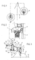
- FIG. 1 Each of these solutions has a disadvantage which constitutes the advantage of the other; this is shown diagrammatically in FIG. 1, on which is shown on the left side a half machine with a pushed broom (a) which is remote from the suction nozzle (c) of a vehicle (d) and on the right side half a machine with a broom drawn (b) not making it easy to reach a waste.
- 3rd broom an optional search broom, called “3rd broom” referenced (e) in FIG 2 and mounted on an articulated arm (f) capable of move across the front width of the vehicle.
- the function of this 3 rd broom, called “SEARCH” function is to increase the sweeping surface and bring the waste to the main brooms, the latter having the function of directing said waste to the suction nozzle.
- the object of the present invention is to develop a "pulled broom" type device capable of integrating a pushed broom function to increase the scanning surface.
- this device must be simple and economically feasible.
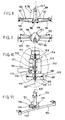
- an erasing spring (24), combined with a pivot (29) allowing the pivoting of the parallelogram system in a vertical plane, is preferentially provided on each brush holder device.
- FIG. 4 shows, in view from above, and with respect to the direction of displacement (25) of the carrier vehicle, that the same arm (7) pivoting by an angle ( ⁇ ) about the axis of rotation (26) of the second rotating means (2) can work as a pushed broom (27) or as a pulled broom (28).
- the pivoting of the arm (7) and its locking in position is controlled from the driving position of the vehicle and it is for example preferably limited to 270 ° and can be blocked in any intermediate position that the driver of the vehicle chooses according to the scan area he wants to reach.
- the second development of the invention relates more particularly to a locking device for the rear axle of said vehicle, the vehicle being a four-wheel steering vehicle.
- This type of vehicle usually drives at a reduced speed even when not in a cleaning situation.
- the plaintiff's goal is to design a cleaning vehicle that can travel at a speed of 80 km / hour on the road.
- Axle locks are known.
- the Applicant has developed a specific device described below.
- the vehicle comprises a system for controlling the angle of the rear wheels on the angle of the front wheels which drives a hydraulic block of the rear steering cylinders.
- the movement of the forward direction of a vehicle according to the invention is provided by mechanical and hydraulic elements (cylinders and bars) and the rear direction is slaved to the forward direction following the same principle with steering cylinders (101, 102) and bars or links (103, 104) associated with the rear axle (105).
- the blocking device operates as follows:
- the four wheels are steered; the hydraulic pressure present in the locking cylinder (116) opposes the force of the spring (117), the piston (114) is in the up position.
- the lower plate connecting the steering rods (103, 104) can rotate freely under the action of the hydraulic cylinders taken in fixed points on the axle and fixed plate.
- the electronic servo system slaving the angle of the rear wheels on the angle of the front wheels according to the steering angle of the front axle, in a manner known per se.
- this electronic system drives a hydraulic power unit of the rear steering cylinders (101, 102) just enough to obtain a corresponding steering of the axle In the rear, this system is very responsive because it continuously corrects the rear steering angle with respect to the steering angle.
- This mechanical locking device is a guarantee of security.
- the unrepresented angle sensors of the front wheels are deactivated by the lowering of the cylinder whose end of travel is detected by the sensors (120, 121).
- This low-pressure system represents an advantage in terms of safety, the locking capacity of the axle is in no way impaired (thanks to the spring) and avoids any rolling in four-wheel steering in case of hydraulic failure.
- FIGs 8 to 10 symbolically represent the plates (108) and (109) in the form of ellipses, but any other suitable form may be considered, including the preferred but non-limiting form of the upper plate shown in Figure (11).
- This shape has two lateral openings (125, 126) so as to completely cover an overlap zone (127) around the trajectory (124) of the conical housing and of greater width than the upper diameter of said housing.
- the wiper seal (128) is arranged such that it completely protects this area (127).
- the third development of the invention relates to a suspension device for this cleaning-sweeping vehicle.
- This type of vehicle usually drives at a reduced speed even when not in a cleaning situation.
- a certain number of stability problems must be solved, especially in turns, which are accentuated if the vehicle is narrow.
- the Applicant has carried out a fine analysis of the suspension systems for narrow vehicles, and with a progressive center of gravity in use.
- the objective is therefore to provide a suspension system to best stabilize a vehicle with narrow lanes and high center of gravity.
- the invention which consists of a self-propelled vehicle for the cleaning of road surfaces, of the type mainly comprising a chassis mounted on a front wheel set and a rear wheel set and carrying a driving cabin to the before, a waste collection tank and its suction turbine connected to a suction tube passing through the frame and opening into a suction nozzle above the surface to be cleaned and behind a brushing assembly performing a function of sweeping the surface, said vehicle may further be equipped with means performing additional functions of cleaning the surface such as washing thereof, vehicle whose wheel trains comprise a spring suspension system, characterized in that that it comprises a system of connection between the chassis and an axle of a wheel train maintaining the vertical springs with a center distance modeled on the way of the veh icule.
- It consists mainly of two springs (c ') mounted between an axle (a') carrying the wheels (b ') and a frame not shown, and a suspension system of triangulation (d') mounted by a system to ball joint (e ') on the axle (a').
- the pivot point of the roll is on the median plane of the chassis.
- the lever arm dimension (x) and the spring stiffness (c ') determine the maximum roll angle at equivalent loads.
- the purpose sought by the applicant is to achieve a train with a spring suspension system, which reduces the width of the vehicle, while meeting all the constraints indicated above.
- This goal is achieved differently for the front and rear axle because of the constraints of presence of a driver's cab and a suction pipe near the front axle.
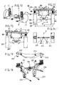
- a rear axle according to the invention comprises a suspension system (201) with springs, in connection with a transverse bar or a chassis cross member (202) and secondly with an axle (203) of wheels (204). ).
- the link between the chassis cross member (202) and the axle (203) is formed by two fixed offset frames (205), one end (206) of which is fixedly mounted on the axle (203) and between the two wheels. , and whose other end (207) is placed above a wheel and carries one end of the frame cross member through a spring (208) working in compression.
- the two offset frames (205) are placed symmetrically with respect to the median plane (P) of the chassis of the vehicle, and their shape and their dimensions make it possible to raise the springs and to place them in line with the wheels, while allowing to reduce the wheel spacing from a standard design and maintain the dimension (x) at the value selected by the roll calculation. (See Figures 12, 13 and 15).
- the spring device is completed by two rubber stops (210) mounted inside each of the springs to limit the vertical displacement of the cross member (202) in the event of impact, while playing a role in damping. .
- the force applied to the suspension spring is proportional to the dimension (x) and determines the arrow ( Figure 15).
- shock absorbers determines the speed with which the pendulum movements of the body will be contained.
- the rear axle according to the invention also comprises a damping device consisting of two damping cylinders (211), each mounted vertically, between firstly bearings (226) of the chassis cross member (202) and secondly one of the offset frames (205), in the example of FIG. 18.
- a damping device consisting of two damping cylinders (211), each mounted vertically, between firstly bearings (226) of the chassis cross member (202) and secondly one of the offset frames (205), in the example of FIG. 18.
- the spacing of the two jacks can also be maintained by a horizontal bar (209) as in Figure 13.
- the dimension (x) being identical to the half-spacing of the wheels instead of being significantly lower as in the standard design, said dimension requires less stiffness and a lower damping capacity, vehicle weight equivalent, which reduces the dimensions of springs and dampers.
- the spacing of the springs (2x) is modeled on the vehicle track (that is to say that the value 2x is greater than the spacing of the wheels) or substantially equal to the z-spacing of said wheels, to reduce the effort on the springs, like the important spacing of the dampers makes it possible to stabilize and to damp more quickly the box.
- the rear axle according to the invention is furthermore suspended by a suspension assembly (212) formed on the one hand by two lower guide rods (213) mounted under the axle (203) by pivots (215) and pivotable in a plane parallel to the frame and on the other hand an upper triangle (214), formed of two V-links (214), and mounted by a pivot system (216) under the horizontal bar (209) of the suspension system.
- a suspension assembly formed on the one hand by two lower guide rods (213) mounted under the axle (203) by pivots (215) and pivotable in a plane parallel to the frame and on the other hand an upper triangle (214), formed of two V-links (214), and mounted by a pivot system (216) under the horizontal bar (209) of the suspension system.
- the lower connecting rods (213) absorb the longitudinal force of the vehicle related to the damping, and allow the vertical movement of the axle by the pivots (215).
- the upper triangle (214) makes it possible to cash the lateral forces of the vehicle and also makes it possible to cash the vertical displacements of the axle by the pivot (216).
- the damping device comprises as before two damping cylinders (211), each mounted vertically between the upper cabin and the offset structures (205).
- the suspension assembly (212) is not modified because the upper triangle (214) does not interfere with the passage of the wheels.
- the driver's cab not shown is positioned above the wheels.
- the springs are split and arranged in pairs on the front and the rear of each wheel, in a lowered position relative to the top of a wheel.
- a pivoting structure (218) mounted on the central pivot (219) of the axle comprises two arms (218a and 218b) arranged parallel to the rolling plane of a wheel and inside thereof.
- Each of the arms having its ends curved at 90 ° and each carrying a spring, so that each pair of springs (220 and 221) can pivot in a horizontal plane around a wheel during each steering operation.
- Each spring (220 and 221) is mounted in compression between a plate (222, 223) integral with one end of an arm (218a, 218b) and the underside of the unrepresented chassis of the vehicle, and can be equipped as before of a stop (210) inner rubber.
- This disposition of the springs makes it possible to obtain a large spring center distance without occupying the space above the wheel and makes it possible to lower the cabin and thus to reduce the height of the vehicle body.
- damping cylinders (211) are deported to allow steering wheels, they are provided between the underside of the frame and a lug (224 or 225) fixed under one of the plates (222 or 223) of each pivoting structure (218).
- the suspension assembly (212) is not modified.
- FIGS. 25 to 32 show some examples of the situation of a rear axle according to the invention that can occur during the work of the vehicle equipped with it, the arrows (229) and (228) show the amplitudes of the dampings and the springs .
- Figures 31 and 32 show the detent movement of the damping rods after a shock to the vehicle in Figures 29 and 30.
- a vehicle according to the invention equipped with a brushing assembly according to the invention has a brushing surface (and especially in width) increased relative to the width of the vehicle.
- the vehicle may have a width of less than 1.60 m while maintaining a good pick-up capacity, good stability even at high speed, and can drive safely both at low working speeds and at higher speeds on the road.
- these equipments can also, and conversely, be provided on larger vehicles whose sweeping surface and / or stability are desired to increase and possibly to reduce the tank height to equal volume.
Priority Applications (1)
| Application Number | Priority Date | Filing Date | Title |
|---|---|---|---|
| EP09007334A EP2098387B1 (de) | 2005-09-28 | 2006-09-13 | Reinigungsfahrzeug |
Applications Claiming Priority (3)
| Application Number | Priority Date | Filing Date | Title |
|---|---|---|---|
| FR0509875A FR2891198B1 (fr) | 2005-09-28 | 2005-09-28 | Systeme de liaison a ressort pour vehicule etroit |
| FR0511587A FR2893297B1 (fr) | 2005-11-16 | 2005-11-16 | Dispositif de blocage d'essieu arriere pour un vehicule de nettoyage de voirie a quatre roues directrices. |
| FR0511875A FR2893639B1 (fr) | 2005-11-24 | 2005-11-24 | Dispositif porte-balai pour vehicule de nettoyage de voirie de type balai "pousse" pouvant integrer une fonction balai "tire" |
Related Child Applications (1)
| Application Number | Title | Priority Date | Filing Date |
|---|---|---|---|
| EP09007334A Division EP2098387B1 (de) | 2005-09-28 | 2006-09-13 | Reinigungsfahrzeug |
Publications (3)
| Publication Number | Publication Date |
|---|---|
| EP1769950A2 true EP1769950A2 (de) | 2007-04-04 |
| EP1769950A3 EP1769950A3 (de) | 2008-05-07 |
| EP1769950B1 EP1769950B1 (de) | 2009-11-18 |
Family
ID=37546928
Family Applications (2)
| Application Number | Title | Priority Date | Filing Date |
|---|---|---|---|
| EP06366004A Active EP1769950B1 (de) | 2005-09-28 | 2006-09-13 | Bürstenhaltevorrichtung und Reinigungsfahrzeug mit einer solchen Vorrichtung |
| EP09007334A Active EP2098387B1 (de) | 2005-09-28 | 2006-09-13 | Reinigungsfahrzeug |
Family Applications After (1)
| Application Number | Title | Priority Date | Filing Date |
|---|---|---|---|
| EP09007334A Active EP2098387B1 (de) | 2005-09-28 | 2006-09-13 | Reinigungsfahrzeug |
Country Status (3)
| Country | Link |
|---|---|
| EP (2) | EP1769950B1 (de) |
| AT (1) | ATE449215T1 (de) |
| DE (1) | DE602006010498D1 (de) |
Cited By (9)
| Publication number | Priority date | Publication date | Assignee | Title |
|---|---|---|---|---|
| EP2106935A1 (de) * | 2008-03-10 | 2009-10-07 | Deere & Company | Fahrzeug |
| WO2012171580A1 (de) | 2011-06-17 | 2012-12-20 | Alfred Kärcher Gmbh & Co. Kg | Kehrfahrzeug |
| WO2012171579A1 (de) | 2011-06-17 | 2012-12-20 | Alfred Kärcher Gmbh & Co. Kg | Kehrfahrzeug mit bürstenteller-verstelleinrichtung |
| CN106192833A (zh) * | 2016-08-30 | 2016-12-07 | 珠海亿华电动车辆有限公司 | 一种扫刷装置和电动地面清扫机 |
| CN108560464A (zh) * | 2018-05-18 | 2018-09-21 | 邢台职业技术学院 | 一种环卫清扫车 |
| CN108612015A (zh) * | 2018-05-24 | 2018-10-02 | 扬州金威环保科技有限公司 | 一种可快速互换的模块化湿扫洗地装置 |
| CN109235338A (zh) * | 2018-10-12 | 2019-01-18 | 扬州三源机械有限公司 | 一种全方位无死角扫盘机构 |
| CN111942262A (zh) * | 2020-09-21 | 2020-11-17 | 洛阳安驰汽车制造有限公司 | 一种精密设备载车 |
| CN112681207A (zh) * | 2020-12-24 | 2021-04-20 | 北京泛华新兴体育产业股份有限公司 | 一种冰雪清除装置及使用该装置的除雪车 |
Families Citing this family (3)
| Publication number | Priority date | Publication date | Assignee | Title |
|---|---|---|---|---|
| CN107969206A (zh) * | 2017-12-24 | 2018-05-01 | 广西广付金商贸有限公司 | 一种新型的红薯收获机用清洁装置 |
| CN108487152B (zh) * | 2018-04-03 | 2020-04-14 | 益阳瀚鑫机械制造有限公司 | 一种清洁范围可调的环保道路清洁车 |
| CN112663546B (zh) * | 2020-12-23 | 2022-03-18 | 提尔环保科技江苏有限公司 | 一种驾驶式扫地机 |
Citations (2)
| Publication number | Priority date | Publication date | Assignee | Title |
|---|---|---|---|---|
| US754521A (en) | 1903-06-05 | 1904-03-15 | Eli C Vale | Separable link. |
| DE10106471A1 (de) | 2001-02-13 | 2002-08-14 | Kuepper Weisser Gmbh | Kehrmaschine mit linear verlagerbarem Tellerbesen |
Family Cites Families (10)
| Publication number | Priority date | Publication date | Assignee | Title |
|---|---|---|---|---|
| US2139185A (en) * | 1936-08-12 | 1938-12-06 | Teves Kg Alfred | Pressure actuated piston lock release |
| SU492403A1 (ru) * | 1973-11-26 | 1975-11-25 | Головное Союзное Конструкторское Бюро По Автобусам Министерства Автомобильной Промышленности Ссср | Независима подвеска колеса транспортного средства |
| GB8529601D0 (en) * | 1985-12-02 | 1986-01-08 | Lotus Group Plc | Vehicle with front & rear wheel steering |
| IT1195887B (it) * | 1986-07-31 | 1988-10-27 | Dulevo Spa | Macchina spazzatrice stradale per la raccolta di rifiuti |
| US4941543A (en) * | 1988-12-23 | 1990-07-17 | Dlma Transportation Inc. | Rear wheel suspension and steering system |
| US6086074A (en) * | 1995-11-15 | 2000-07-11 | Oshkosh Truck Corporation | Steering lock system |
| WO1997026170A1 (en) * | 1996-01-17 | 1997-07-24 | Carlton John Davis | Control system for a steerable axle and a steerable axle |
| GB2360499B (en) * | 2000-03-21 | 2002-12-31 | Carlton John Davis | Control apparatus and method for a steerable axle |
| FR2808733B1 (fr) * | 2000-05-09 | 2002-07-12 | Mathieu Yno S A | Ensemble de pieces pour realiser un essieu de vehicule de voirie |
| ATE259733T1 (de) * | 2001-03-20 | 2004-03-15 | Faun Gmbh | Kraftfahrzeug mit mindestens einer hinter-achse mit lenkbaren hinterrädern |
-
2006
- 2006-09-13 AT AT06366004T patent/ATE449215T1/de not_active IP Right Cessation
- 2006-09-13 EP EP06366004A patent/EP1769950B1/de active Active
- 2006-09-13 DE DE602006010498T patent/DE602006010498D1/de active Active
- 2006-09-13 EP EP09007334A patent/EP2098387B1/de active Active
Patent Citations (2)
| Publication number | Priority date | Publication date | Assignee | Title |
|---|---|---|---|---|
| US754521A (en) | 1903-06-05 | 1904-03-15 | Eli C Vale | Separable link. |
| DE10106471A1 (de) | 2001-02-13 | 2002-08-14 | Kuepper Weisser Gmbh | Kehrmaschine mit linear verlagerbarem Tellerbesen |
Cited By (16)
| Publication number | Priority date | Publication date | Assignee | Title |
|---|---|---|---|---|
| EP2106935A1 (de) * | 2008-03-10 | 2009-10-07 | Deere & Company | Fahrzeug |
| US7938415B2 (en) | 2008-03-10 | 2011-05-10 | Deere & Company | Suspended axle for sprayer |
| AU2009200810B2 (en) * | 2008-03-10 | 2014-07-31 | Deere & Company | Suspended axle for sprayer |
| WO2012171580A1 (de) | 2011-06-17 | 2012-12-20 | Alfred Kärcher Gmbh & Co. Kg | Kehrfahrzeug |
| WO2012171579A1 (de) | 2011-06-17 | 2012-12-20 | Alfred Kärcher Gmbh & Co. Kg | Kehrfahrzeug mit bürstenteller-verstelleinrichtung |
| CN103608521A (zh) * | 2011-06-17 | 2014-02-26 | 阿尔弗雷德·凯驰两合公司 | 清扫车 |
| US9249547B2 (en) | 2011-06-17 | 2016-02-02 | Alfred Kärcher Gmbh & Co. Kg | Sweeping vehicle |
| CN106192833B (zh) * | 2016-08-30 | 2018-06-29 | 珠海亿华电动车辆有限公司 | 一种扫刷装置和电动地面清扫机 |
| CN106192833A (zh) * | 2016-08-30 | 2016-12-07 | 珠海亿华电动车辆有限公司 | 一种扫刷装置和电动地面清扫机 |
| CN108560464A (zh) * | 2018-05-18 | 2018-09-21 | 邢台职业技术学院 | 一种环卫清扫车 |
| CN108612015A (zh) * | 2018-05-24 | 2018-10-02 | 扬州金威环保科技有限公司 | 一种可快速互换的模块化湿扫洗地装置 |
| CN109235338A (zh) * | 2018-10-12 | 2019-01-18 | 扬州三源机械有限公司 | 一种全方位无死角扫盘机构 |
| CN111942262A (zh) * | 2020-09-21 | 2020-11-17 | 洛阳安驰汽车制造有限公司 | 一种精密设备载车 |
| CN111942262B (zh) * | 2020-09-21 | 2024-04-23 | 洛阳安驰汽车制造有限公司 | 一种精密设备载车 |
| CN112681207A (zh) * | 2020-12-24 | 2021-04-20 | 北京泛华新兴体育产业股份有限公司 | 一种冰雪清除装置及使用该装置的除雪车 |
| CN112681207B (zh) * | 2020-12-24 | 2022-06-28 | 北京泛华新兴体育产业股份有限公司 | 一种冰雪清除装置及使用该装置的除雪车 |
Also Published As
| Publication number | Publication date |
|---|---|
| EP2098387B1 (de) | 2012-04-18 |
| EP2098387A2 (de) | 2009-09-09 |
| EP2098387A3 (de) | 2009-11-18 |
| DE602006010498D1 (de) | 2009-12-31 |
| ATE449215T1 (de) | 2009-12-15 |
| EP1769950A3 (de) | 2008-05-07 |
| EP1769950B1 (de) | 2009-11-18 |
Similar Documents
| Publication | Publication Date | Title |
|---|---|---|
| EP2098387B1 (de) | Reinigungsfahrzeug | |
| EP1773609B1 (de) | Kraftfahrzeug mit begrenztem neigewinkel | |
| EP0726198A2 (de) | Radaufhängung für ein Fahrzeug mit lenkbarem Vorderrad und Fahrzeug mit dieser Radaufhängung | |
| WO2006067087A1 (fr) | Essieu suspendu pour véhicule | |
| EP0945551B1 (de) | Kehrvorrichtung für Arbeitsfahrzeuge | |
| EP2552760A1 (de) | Schienenfahrzeug mit einem waggon mit eigenständigen stromlinienelementen zur verbesserung der aerodynamischen leistung des besagten waggons | |
| EP2782814B1 (de) | Kompaktes stadtfahrzeug | |
| FR2630683A1 (fr) | Vehicule pour deplacer des vehicules sur rails | |
| FR2694240A1 (fr) | Véhicule automobile à empattement variable. | |
| EP3691959B1 (de) | Koppelbares automotives strassenfahrzeug mit kompakter lenkung und aufhängung | |
| EP3798363B1 (de) | Strassenkehrmaschine | |
| EP3698996A1 (de) | Bidirektionelles aufhängungssystem für achse mit unabhängigen rädern eines fahrzeugs | |
| FR2640220A1 (fr) | Vehicule articule bidirectionnel guidable, notamment autobus articule | |
| FR2893639A1 (fr) | Dispositif porte-balai pour vehicule de nettoyage de voirie de type balai "pousse" pouvant integrer une fonction balai "tire" | |
| EP0750072B1 (de) | Selbstfahrende kompakte Hochleistungsstadtkehrmaschine mit umgekehrt montierter Turbine | |
| FR2605907A1 (fr) | Dispositif combine d'aspiration et de nettoyage monte sur un vehicule leger autonome pour aspiration de dechets industriels et urbains | |
| FR2911571A1 (fr) | Dispositif de passage d'un mode quatre roues directrices pour vehicule automoteur de nettoyage de voiries | |
| FR2491005A1 (fr) | Vehicules susceptibles de circuler soit sur route soit sur voie ferree | |
| FR2891198A1 (fr) | Systeme de liaison a ressort pour vehicule etroit | |
| FR3000666A1 (fr) | Vehicule pour l'embarquement et le transport d'une personne sur fauteuil roulant | |
| FR2893297A1 (fr) | Dispositif de blocage d'essieu arriere pour un vehicule de nettoyage de voirie a quatre roues directrices. | |
| EP2362923B1 (de) | Sammelvorrichtung von strassengegenständen | |
| FR2800400A1 (fr) | Vehicule automoteur multifonction pour l'entretien des espaces verts | |
| WO2022023378A1 (fr) | Train de roulage pour véhicule amphibie | |
| EP2103202B1 (de) | Arbeitsblock zum Zerschneiden und/oder Häckseln von Pflanzen für den Transport mit einem Trägerfahrzeug mit Hilfe eines Arms |
Legal Events
| Date | Code | Title | Description |
|---|---|---|---|
| PUAI | Public reference made under article 153(3) epc to a published international application that has entered the european phase |
Free format text: ORIGINAL CODE: 0009012 |
|
| AK | Designated contracting states |
Kind code of ref document: A2 Designated state(s): AT BE BG CH CY CZ DE DK EE ES FI FR GB GR HU IE IS IT LI LT LU LV MC NL PL PT RO SE SI SK TR |
|
| AX | Request for extension of the european patent |
Extension state: AL BA HR MK YU |
|
| PUAL | Search report despatched |
Free format text: ORIGINAL CODE: 0009013 |
|
| AK | Designated contracting states |
Kind code of ref document: A3 Designated state(s): AT BE BG CH CY CZ DE DK EE ES FI FR GB GR HU IE IS IT LI LT LU LV MC NL PL PT RO SE SI SK TR |
|
| AX | Request for extension of the european patent |
Extension state: AL BA HR MK RS |
|
| RIC1 | Information provided on ipc code assigned before grant |
Ipc: E01H 1/05 20060101AFI20080401BHEP Ipc: B60G 9/04 20060101ALI20080401BHEP Ipc: E01H 1/02 20060101ALI20080401BHEP Ipc: B62D 7/15 20060101ALI20080401BHEP Ipc: B60G 15/06 20060101ALI20080401BHEP Ipc: B62D 9/00 20060101ALI20080401BHEP |
|
| 17P | Request for examination filed |
Effective date: 20081107 |
|
| 17Q | First examination report despatched |
Effective date: 20081204 |
|
| AKX | Designation fees paid |
Designated state(s): AT BE BG CH CY CZ DE DK EE ES FI FR GB GR HU IE IS IT LI LT LU LV MC NL PL PT RO SE SI SK TR |
|
| RAP1 | Party data changed (applicant data changed or rights of an application transferred) |
Owner name: MATHIEU |
|
| GRAP | Despatch of communication of intention to grant a patent |
Free format text: ORIGINAL CODE: EPIDOSNIGR1 |
|
| RTI1 | Title (correction) |
Free format text: BRUSH HOLDING DEVICE AND CLEANING VEHICLE WITH SUCH A DEVICE |
|
| GRAS | Grant fee paid |
Free format text: ORIGINAL CODE: EPIDOSNIGR3 |
|
| GRAA | (expected) grant |
Free format text: ORIGINAL CODE: 0009210 |
|
| AK | Designated contracting states |
Kind code of ref document: B1 Designated state(s): AT BE BG CH CY CZ DE DK EE ES FI FR GB GR HU IE IS IT LI LT LU LV MC NL PL PT RO SE SI SK TR |
|
| REG | Reference to a national code |
Ref country code: GB Ref legal event code: FG4D Free format text: NOT ENGLISH |
|
| REG | Reference to a national code |
Ref country code: CH Ref legal event code: EP |
|
| REG | Reference to a national code |
Ref country code: IE Ref legal event code: FG4D |
|
| REF | Corresponds to: |
Ref document number: 602006010498 Country of ref document: DE Date of ref document: 20091231 Kind code of ref document: P |
|
| REG | Reference to a national code |
Ref country code: NL Ref legal event code: VDEP Effective date: 20091118 |
|
| LTIE | Lt: invalidation of european patent or patent extension |
Effective date: 20091118 |
|
| PG25 | Lapsed in a contracting state [announced via postgrant information from national office to epo] |
Ref country code: ES Free format text: LAPSE BECAUSE OF FAILURE TO SUBMIT A TRANSLATION OF THE DESCRIPTION OR TO PAY THE FEE WITHIN THE PRESCRIBED TIME-LIMIT Effective date: 20100228 Ref country code: PT Free format text: LAPSE BECAUSE OF FAILURE TO SUBMIT A TRANSLATION OF THE DESCRIPTION OR TO PAY THE FEE WITHIN THE PRESCRIBED TIME-LIMIT Effective date: 20100318 Ref country code: SE Free format text: LAPSE BECAUSE OF FAILURE TO SUBMIT A TRANSLATION OF THE DESCRIPTION OR TO PAY THE FEE WITHIN THE PRESCRIBED TIME-LIMIT Effective date: 20091118 Ref country code: LT Free format text: LAPSE BECAUSE OF FAILURE TO SUBMIT A TRANSLATION OF THE DESCRIPTION OR TO PAY THE FEE WITHIN THE PRESCRIBED TIME-LIMIT Effective date: 20091118 Ref country code: FI Free format text: LAPSE BECAUSE OF FAILURE TO SUBMIT A TRANSLATION OF THE DESCRIPTION OR TO PAY THE FEE WITHIN THE PRESCRIBED TIME-LIMIT Effective date: 20091118 Ref country code: IS Free format text: LAPSE BECAUSE OF FAILURE TO SUBMIT A TRANSLATION OF THE DESCRIPTION OR TO PAY THE FEE WITHIN THE PRESCRIBED TIME-LIMIT Effective date: 20100318 |
|
| PG25 | Lapsed in a contracting state [announced via postgrant information from national office to epo] |
Ref country code: PL Free format text: LAPSE BECAUSE OF FAILURE TO SUBMIT A TRANSLATION OF THE DESCRIPTION OR TO PAY THE FEE WITHIN THE PRESCRIBED TIME-LIMIT Effective date: 20091118 Ref country code: LV Free format text: LAPSE BECAUSE OF FAILURE TO SUBMIT A TRANSLATION OF THE DESCRIPTION OR TO PAY THE FEE WITHIN THE PRESCRIBED TIME-LIMIT Effective date: 20091118 Ref country code: SI Free format text: LAPSE BECAUSE OF FAILURE TO SUBMIT A TRANSLATION OF THE DESCRIPTION OR TO PAY THE FEE WITHIN THE PRESCRIBED TIME-LIMIT Effective date: 20091118 Ref country code: CY Free format text: LAPSE BECAUSE OF FAILURE TO SUBMIT A TRANSLATION OF THE DESCRIPTION OR TO PAY THE FEE WITHIN THE PRESCRIBED TIME-LIMIT Effective date: 20091118 |
|
| REG | Reference to a national code |
Ref country code: IE Ref legal event code: FD4D |
|
| PG25 | Lapsed in a contracting state [announced via postgrant information from national office to epo] |
Ref country code: AT Free format text: LAPSE BECAUSE OF FAILURE TO SUBMIT A TRANSLATION OF THE DESCRIPTION OR TO PAY THE FEE WITHIN THE PRESCRIBED TIME-LIMIT Effective date: 20091118 |
|
| PG25 | Lapsed in a contracting state [announced via postgrant information from national office to epo] |
Ref country code: EE Free format text: LAPSE BECAUSE OF FAILURE TO SUBMIT A TRANSLATION OF THE DESCRIPTION OR TO PAY THE FEE WITHIN THE PRESCRIBED TIME-LIMIT Effective date: 20091118 Ref country code: DK Free format text: LAPSE BECAUSE OF FAILURE TO SUBMIT A TRANSLATION OF THE DESCRIPTION OR TO PAY THE FEE WITHIN THE PRESCRIBED TIME-LIMIT Effective date: 20091118 Ref country code: RO Free format text: LAPSE BECAUSE OF FAILURE TO SUBMIT A TRANSLATION OF THE DESCRIPTION OR TO PAY THE FEE WITHIN THE PRESCRIBED TIME-LIMIT Effective date: 20091118 Ref country code: NL Free format text: LAPSE BECAUSE OF FAILURE TO SUBMIT A TRANSLATION OF THE DESCRIPTION OR TO PAY THE FEE WITHIN THE PRESCRIBED TIME-LIMIT Effective date: 20091118 Ref country code: IE Free format text: LAPSE BECAUSE OF FAILURE TO SUBMIT A TRANSLATION OF THE DESCRIPTION OR TO PAY THE FEE WITHIN THE PRESCRIBED TIME-LIMIT Effective date: 20091118 Ref country code: BG Free format text: LAPSE BECAUSE OF FAILURE TO SUBMIT A TRANSLATION OF THE DESCRIPTION OR TO PAY THE FEE WITHIN THE PRESCRIBED TIME-LIMIT Effective date: 20100218 |
|
| PG25 | Lapsed in a contracting state [announced via postgrant information from national office to epo] |
Ref country code: CZ Free format text: LAPSE BECAUSE OF FAILURE TO SUBMIT A TRANSLATION OF THE DESCRIPTION OR TO PAY THE FEE WITHIN THE PRESCRIBED TIME-LIMIT Effective date: 20091118 Ref country code: SK Free format text: LAPSE BECAUSE OF FAILURE TO SUBMIT A TRANSLATION OF THE DESCRIPTION OR TO PAY THE FEE WITHIN THE PRESCRIBED TIME-LIMIT Effective date: 20091118 |
|
| PLBE | No opposition filed within time limit |
Free format text: ORIGINAL CODE: 0009261 |
|
| STAA | Information on the status of an ep patent application or granted ep patent |
Free format text: STATUS: NO OPPOSITION FILED WITHIN TIME LIMIT |
|
| 26N | No opposition filed |
Effective date: 20100819 |
|
| PG25 | Lapsed in a contracting state [announced via postgrant information from national office to epo] |
Ref country code: GR Free format text: LAPSE BECAUSE OF FAILURE TO SUBMIT A TRANSLATION OF THE DESCRIPTION OR TO PAY THE FEE WITHIN THE PRESCRIBED TIME-LIMIT Effective date: 20100219 |
|
| BERE | Be: lapsed |
Owner name: MATHIEU Effective date: 20100930 |
|
| PG25 | Lapsed in a contracting state [announced via postgrant information from national office to epo] |
Ref country code: IT Free format text: LAPSE BECAUSE OF FAILURE TO SUBMIT A TRANSLATION OF THE DESCRIPTION OR TO PAY THE FEE WITHIN THE PRESCRIBED TIME-LIMIT Effective date: 20091118 |
|
| PG25 | Lapsed in a contracting state [announced via postgrant information from national office to epo] |
Ref country code: MC Free format text: LAPSE BECAUSE OF NON-PAYMENT OF DUE FEES Effective date: 20100930 |
|
| REG | Reference to a national code |
Ref country code: CH Ref legal event code: PL |
|
| GBPC | Gb: european patent ceased through non-payment of renewal fee |
Effective date: 20100913 |
|
| REG | Reference to a national code |
Ref country code: DE Ref legal event code: R119 Ref document number: 602006010498 Country of ref document: DE Effective date: 20110401 |
|
| PG25 | Lapsed in a contracting state [announced via postgrant information from national office to epo] |
Ref country code: BE Free format text: LAPSE BECAUSE OF NON-PAYMENT OF DUE FEES Effective date: 20100930 Ref country code: DE Free format text: LAPSE BECAUSE OF NON-PAYMENT OF DUE FEES Effective date: 20110401 Ref country code: LI Free format text: LAPSE BECAUSE OF NON-PAYMENT OF DUE FEES Effective date: 20100930 Ref country code: CH Free format text: LAPSE BECAUSE OF NON-PAYMENT OF DUE FEES Effective date: 20100930 |
|
| PG25 | Lapsed in a contracting state [announced via postgrant information from national office to epo] |
Ref country code: GB Free format text: LAPSE BECAUSE OF NON-PAYMENT OF DUE FEES Effective date: 20100913 |
|
| PG25 | Lapsed in a contracting state [announced via postgrant information from national office to epo] |
Ref country code: LU Free format text: LAPSE BECAUSE OF NON-PAYMENT OF DUE FEES Effective date: 20100913 Ref country code: HU Free format text: LAPSE BECAUSE OF FAILURE TO SUBMIT A TRANSLATION OF THE DESCRIPTION OR TO PAY THE FEE WITHIN THE PRESCRIBED TIME-LIMIT Effective date: 20100519 |
|
| PG25 | Lapsed in a contracting state [announced via postgrant information from national office to epo] |
Ref country code: TR Free format text: LAPSE BECAUSE OF FAILURE TO SUBMIT A TRANSLATION OF THE DESCRIPTION OR TO PAY THE FEE WITHIN THE PRESCRIBED TIME-LIMIT Effective date: 20091118 |
|
| REG | Reference to a national code |
Ref country code: FR Ref legal event code: PLFP Year of fee payment: 11 |
|
| REG | Reference to a national code |
Ref country code: FR Ref legal event code: PLFP Year of fee payment: 12 |
|
| REG | Reference to a national code |
Ref country code: FR Ref legal event code: PLFP Year of fee payment: 13 |
|
| PGFP | Annual fee paid to national office [announced via postgrant information from national office to epo] |
Ref country code: FR Payment date: 20230912 Year of fee payment: 18 |
|
| P01 | Opt-out of the competence of the unified patent court (upc) registered |
Effective date: 20240122 |