EP2782814B1 - Kompaktes stadtfahrzeug - Google Patents
Kompaktes stadtfahrzeug Download PDFInfo
- Publication number
- EP2782814B1 EP2782814B1 EP12806543.0A EP12806543A EP2782814B1 EP 2782814 B1 EP2782814 B1 EP 2782814B1 EP 12806543 A EP12806543 A EP 12806543A EP 2782814 B1 EP2782814 B1 EP 2782814B1
- Authority
- EP
- European Patent Office
- Prior art keywords
- vehicle
- door
- vehicle according
- floor
- chassis
- Prior art date
- Legal status (The legal status is an assumption and is not a legal conclusion. Google has not performed a legal analysis and makes no representation as to the accuracy of the status listed.)
- Not-in-force
Links
- 230000005540 biological transmission Effects 0.000 claims description 9
- 239000000725 suspension Substances 0.000 claims description 7
- 238000010521 absorption reaction Methods 0.000 description 4
- 238000005096 rolling process Methods 0.000 description 4
- 230000035939 shock Effects 0.000 description 4
- 230000002787 reinforcement Effects 0.000 description 2
- 101100536354 Drosophila melanogaster tant gene Proteins 0.000 description 1
- 230000008878 coupling Effects 0.000 description 1
- 238000010168 coupling process Methods 0.000 description 1
- 238000005859 coupling reaction Methods 0.000 description 1
- 238000013016 damping Methods 0.000 description 1
- 239000000463 material Substances 0.000 description 1
- 230000001681 protective effect Effects 0.000 description 1
- 230000000284 resting effect Effects 0.000 description 1
- 230000004083 survival effect Effects 0.000 description 1
Images


Classifications
-
- B—PERFORMING OPERATIONS; TRANSPORTING
- B62—LAND VEHICLES FOR TRAVELLING OTHERWISE THAN ON RAILS
- B62D—MOTOR VEHICLES; TRAILERS
- B62D31/00—Superstructures for passenger vehicles
- B62D31/003—Superstructures for passenger vehicles compact cars, e.g. city cars
-
- B—PERFORMING OPERATIONS; TRANSPORTING
- B60—VEHICLES IN GENERAL
- B60J—WINDOWS, WINDSCREENS, NON-FIXED ROOFS, DOORS, OR SIMILAR DEVICES FOR VEHICLES; REMOVABLE EXTERNAL PROTECTIVE COVERINGS SPECIALLY ADAPTED FOR VEHICLES
- B60J5/00—Doors
- B60J5/02—Doors arranged at the vehicle front
-
- B—PERFORMING OPERATIONS; TRANSPORTING
- B62—LAND VEHICLES FOR TRAVELLING OTHERWISE THAN ON RAILS
- B62D—MOTOR VEHICLES; TRAILERS
- B62D47/00—Motor vehicles or trailers predominantly for carrying passengers
- B62D47/006—Vehicles which can be divided in sub-vehicles; nestable vehicles
-
- B—PERFORMING OPERATIONS; TRANSPORTING
- B62—LAND VEHICLES FOR TRAVELLING OTHERWISE THAN ON RAILS
- B62D—MOTOR VEHICLES; TRAILERS
- B62D61/00—Motor vehicles or trailers, characterised by the arrangement or number of wheels, not otherwise provided for, e.g. four wheels in diamond pattern
- B62D61/06—Motor vehicles or trailers, characterised by the arrangement or number of wheels, not otherwise provided for, e.g. four wheels in diamond pattern with only three wheels
- B62D61/065—Motor vehicles or trailers, characterised by the arrangement or number of wheels, not otherwise provided for, e.g. four wheels in diamond pattern with only three wheels with single rear wheel
-
- B—PERFORMING OPERATIONS; TRANSPORTING
- B62—LAND VEHICLES FOR TRAVELLING OTHERWISE THAN ON RAILS
- B62K—CYCLES; CYCLE FRAMES; CYCLE STEERING DEVICES; RIDER-OPERATED TERMINAL CONTROLS SPECIALLY ADAPTED FOR CYCLES; CYCLE AXLE SUSPENSIONS; CYCLE SIDE-CARS, FORECARS, OR THE LIKE
- B62K5/00—Cycles with handlebars, equipped with three or more main road wheels
- B62K5/02—Tricycles
- B62K5/027—Motorcycles with three wheels
-
- B—PERFORMING OPERATIONS; TRANSPORTING
- B62—LAND VEHICLES FOR TRAVELLING OTHERWISE THAN ON RAILS
- B62K—CYCLES; CYCLE FRAMES; CYCLE STEERING DEVICES; RIDER-OPERATED TERMINAL CONTROLS SPECIALLY ADAPTED FOR CYCLES; CYCLE AXLE SUSPENSIONS; CYCLE SIDE-CARS, FORECARS, OR THE LIKE
- B62K5/00—Cycles with handlebars, equipped with three or more main road wheels
- B62K5/02—Tricycles
- B62K5/05—Tricycles characterised by a single rear wheel
Definitions
- the present invention relates to the technical field of motor vehicles and more specifically to urban motor vehicles.
- the document WO 02/18163 describes a vehicle comprising a chassis equipped with four wheels and two user reception seats, placed side by side and inside a cockpit opening at the front of the vehicle and closed by a tilting door.
- the patent application FR 2 865 706 describes a motor vehicle with three or four wheels cooperating with a motorized rear wheel and two front wheels oriented by a steering system.
- a seat is disposed between the two front wheels so that the driver's legs span the axis passing through the center of the two front wheels.
- the patent US 5,248,011 discloses a vehicle having a frame supporting two motorized front wheels and a steered rear wheel.
- the present invention aims to propose a new urban vehicle designed to have a smaller footprint compared to the previous vehicle while being robust, safe and easy to use.
- FIGS. 1 and 2 are perspective views of a vehicle according to the invention taken respectively from the front and the rear of the vehicle.
- the Figure 3 is a top view of the vehicle according to the invention.
- the Figure 4 is a side view of the vehicle according to the invention.
- FIGS. 5 and 6 are cross-sectional views taken respectively along the lines AA and BB of the Fig. 4 .
- the Figure 7 is a perspective view showing the vehicle with the access door in the raised position.
- the Figure 8 is a view similar to the Fig. 7 showing the vehicle with the access door raised and the floor raised.
- FIGS 9 and 10 are perspective views showing the mechanized chassis of the vehicle respectively taken from the front and rear of the vehicle.
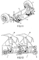
- the Figure 11 illustrates in perspective the front axle of the vehicle according to the invention.
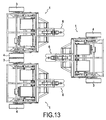
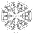
- FIGS. 12 to 14 illustrate different examples of parking a series of vehicles according to the invention.
- the object of the invention relates to a vehicle 1 with three wheels having a generally triangular shape.
- the vehicle 1 comprises a chassis 2 equipped as a front undercarriage, a right front drive wheel 3 and a front left drive wheel 4, considered in the normal direction of travel in the forward direction of the vehicle.
- the drive wheels front right 3 and left 4 are independent of one another.
- the chassis 2 is also equipped with a central rear steering gear train 6 .
- the central rear rolling stock train 6 is a bogie with 2 wheels 6 1 , provided with a vertical axis 6 2 controlled in rotation to control the pivoting of the wheels in the horizontal plane in order to to give direction to the vehicle.
- This rear undercarriage 6 extends in the middle between the front wheels 3, 4 so that the front wheels 3, 4 and the rear undercarriage 6 are established in a triangle as it is clear in FIG. Fig. 3 .
- the base of this triangle which is delimited by the front wheels 3, 4 defines the front of the vehicle while the top of this triangle defined by the rear running gear 6 corresponds to the rear of the vehicle 1 .
- the frame 2 comprises a central rigid structure 2 1 from which extends rearwards, a support structure 2 2 , and towards the front, two longitudinal members 2 3 , extending in parallel to one another.
- the rigid central structure 2 1 has a parallelepipedal general shape extending over the width of the vehicle to serve as a housing and support including a motorized front axle 11 as illustrated in FIG. Fig. 11 .
- the rigid central structure 2 1 is intended to resiliently support by elastic studs 12, the motorized front axle 11.
- This motorized front axle 11 comprises a frame 13 supporting for each front wheel 3, 4 as illustrated in FIG. Fig. 6 , a half-axle 15 connected to a traction motor 16 supported by the frame 13.
- each traction motor 16 is of the electric type.
- the traction motors 16 are connected to a battery pack 17 supported by the support structure 2 2 of the frame.
- the traction motors 16 may be different from electric motors.
- Each half-axle 15 is connected via a transmission 17 to the axis 18 of a front wheel 3, 4 ( Fig. 5 ).
- Each axle 18 of a front wheel 3,4 is supported by a suspension arm 19 provided with guide bearings for a half-axle 15.
- each suspension arm 19 is connected to the frame 2 by means of a suspension system 20 made in any appropriate manner such as by conventional dampers.
- each transmission 17 is made by a belt.
- each wheel before driving 3, 4 is directly equipped with a motor for example electric.
- the motorized axle 11 is thus directly supported by the frame 2 by mounting the frame 13 of the motorized front axle 11 inside the rigid central structure 2 1 .
- the suspension arms 19 thus extend parallel to the longitudinal members 23 and outside thereof.
- the front wheels 3, 4 are positioned to extend slightly back from the end of the side members 2 3 ( Fig. 4 ).
- the central rear rolling stock train 6 is supported by a bracket 25 extending from the support structure 2 .
- This support structure 2 2 advantageously converges for reasons of space in the direction the central rear rolling stock 6 which is thus suspended relative to the bracket 25 ,
- the rear central landing gear 6 is equipped with a damping system 22.
- the vehicle 1 comprises a floor 25 for receiving users supported by the frame 2.
- This floor 25 extends between the front wheels 3,4 and in particular between the longitudinal members 2 3 's opening freely to the front of the vehicle between the left front wheels 4 and right 3.
- the floor 25 is directly accessible from the front of the vehicle 1.
- the longitudinal members 2 3 are provided with reinforcements 26 for supporting the floor 25.
- the reinforcements 26 are fixed at an angle between the central rigid structure 21 and each longitudinal member 23 .
- the spars 23 and the rigid central structure 21 have a generally U-shaped shape delimiting between them a free clearance volume 26 ( Fig. 10 ).
- the floor 25 is mounted on a lift structure 27 such as hinges fixed on the central rigid structure 2 1 to allow clearing the free volume 26.
- the floor is pivoted back and forth so that when the floor 25 is raised, the volume 26 between the rails 23 is cleared.
- the operation of the floor 25 is manual, but it is clear that the pivoting of the floor can be mechanized.
- the floor 25 is illustrated as being made by a single plate.
- the floor 25 can be made in two parts. According to this example, it may be envisaged that the two parts of the floor 25 are hinged not from front to back but at the side members 2 3 so as to pivot laterally.
- the vehicle 1 also comprises a body 28 delimiting above the floor 5 a cockpit 30 opening at the front between the right front wheels 3 and left front 4.
- the body 28 is shown only by members, rails or sleepers for better visibility of the components of the vehicle but it is clear that such a body is intended to receive a covering such as protective walls made of any suitable material.
- the body 28 comprises two side walls 28 1 extending parallel to each other and substantially plumb with respect to the longitudinal members 23 of the frame.
- the two side walls 28 1 are connected to each other at the rear, by a rear wall 28 2 extending vertically substantially in line with the rear face of the central rigid structure 2 1 .
- the side walls 28 1 and the rear wall 28 2 make it possible to delimit the passenger compartment 30 which is accessible by a door 35 enabling the front of the passenger compartment 30 to be closed.
- the door 35 is a door pivotally mounted along a horizontal axis for occupy a lowered position to close access to the floor 25 ( Fig. 1 ) and a raised position ( Fig. 7 ) to release access to the floor 25 to allow the ascent and descent of the vehicle users.
- the door 35 makes it possible to close and open the front of the vehicle, between the front wheels 3, 4.
- the passenger compartment 30 is equipped with two seats 36 mounted side by side and accessible from the front of the vehicle.
- the two seats 36 are mounted on the frame 2 to be oriented towards the front of the vehicle.
- the two seats 36 comprise seats 37 mounted on the top of the central rigid structure 2 1 so that the users in a seated position can have their feet resting on the floor 25.
- the two seats 36 also have backs 37 extending near the rear wall 28 2 of the body.
- the seats 37 of the seats 36 are mounted on the frame to be raised at least partly towards the rear of the vehicle to clear the space towards the front of the vehicle.
- the seats 37 of the seats are mounted on the rigid central structure 2 1 by means of articulations 39 ensuring pivoting back and forth of the seats 37 ( Fig. 7, 8 ). In the raised position of the seat 37, the volume 26 is cleared.
- the tilting door 35 extends as shown in the figures frontally between the two front wheels 3,4 coming to be established at and advantageously before the free end of the longitudinal members 2 1 .
- the tilting door 35 is for example in the form of a support frame 40 having two uprights 40 1 connected together by a rear cross member 40 2 and a front cross member 40 3 extending parallel to the rear cross member 40 2 .
- the front cross member 40 3 is intended to be established in front of the ends of the longitudinal members 2 1 and the floor 25 ( Fig. 1 ).
- the uprights 40 1 rise substantially vertically over a given height to an intermediate connecting web 40 4 extending parallel to the front cross member 40 3 .
- the tilting door 35 thus has between the front cross members 40 3 and intermediate 40 4 , a part 40 5 forming a bumper intended to be established at the front of the vehicle 1 in the lowered position of the door 35.
- this part forming the bumper 40 5 can be adapted to receive various equipment adapted to shocks and / or lighting system for example.
- the frame 2 comprises a shock absorption system occurring on the door 35.
- an absorption system is mounted on the frame at the side members 2 3 to allow to collect a shock likely to intervene on the door in the closed position.
- the uprights 40 1 are inclined towards the rear of the vehicle so that the door 35 can be equipped at this location with a windshield 40 6 .
- the amounts 40 1 are extended by a horizontal portion to the rear cross member 40 2 to form the ceiling 40 7 of the passenger compartment 30 .
- the tilting door 35 is moved by means of a mechanism 50 of the motorized deformable parallelogram type.
- the mechanism 50 comprises two motor arms 51 each connected at one of its ends, by a pivot 52 to the support frame 40 of the overhead door and at the other of its ends, to a motorized horizontal axis 53.
- Each motor arm 51 thus extends in a plane parallel to a side wall 28 1 of the passenger compartment.
- the motorized axis 53 thus extends at the level of the rear wall 28 2 .
- the pivot 52 between each inner arm 51 and the overhead door 35 is arranged at the upright 40 1 of the support frame 40 and in particular at the top of the portion 40 6 forming the windshield.
- the mechanism 50 also comprises a connecting arm 55 articulated between the frame 2 and the support frame 40 of the tilting door 35.
- the link arm 55 extends substantially in the middle of the tilting door c ' that is to say, between the two seats 36.
- This connecting arm 55 is articulated on the one hand, according to a pivot 57 arranged on the frame at the rear wall 28 2 and on the other hand, on a pivot 58 arranged on the front cross member 40 3 of the support frame 40.
- the mechanism 50 limits the size of the tilting door 35 in the raised position.
- the tilting door 35 is equipped with a crossmember 60 designed to be locked with the frame 2 in the lowered position of the door and extend frontally in front of the passenger compartment 30.
- the ends of the crossmember 60 are intended for the lowered position of the door 35, to engage in locking housings 61 provided on the vertical walls 28 1 of the frame.
- the crossmember 60 is locked at both ends, the chassis 2 extending inside the passenger compartment with respect to the support frame 40.
- the locking housing 61 are arranged each in the form of a slideway for receiving the ends of the crossmember 60 during the lowering movement of the door 35.
- the crossmember 60 is mounted on the connecting arm 55.
- the connecting arm 55 has a horizontal part on which is fixed the crossbar 60.
- the horizontal portion of the connecting arm 55 is extended by connecting portions inclined in opposite directions for to be connected respectively to pivots 57 and 58.
- the safety cross member 60 is adapted to support equipment 70 for controlling and controlling the vehicle.
- the crossmember 60 can advantageously be dressed to form the dashboard of the vehicle.
- the equipment 70 for driving the vehicle makes it possible to drive a control unit for the traction motors 16.
- These control and control equipment 70 comprise a mechanical or electrical steering system.
- the system comprises a steering wheel carried by the cross member 60. This steering wheel acts on a gear train for cooperating in the lowered position of the door, with a gear a transmission shaft extending between the seats to a coupling system 71 acting on the steering rear running gear 6. The rotation of the steering wheel allows through this mechanical kinematics, to control the orientation of this steering rear running gear 6.
- the vehicle 1 has a small footprint such as, for example, a height equal to 1.7 meters, a length of 1.9 meters and a width of 2 meters. Due to its chassis 2 of generally triangular shape and the kinematics of its door 35, such a vehicle can for parking, interpenetrate with another vehicle 1 of the same type. As is more particularly apparent from the Fig. 12 in order to interpenetrate the vehicles 1 into each other, it suffices to place the tilting door 35 in the raised position and to raise the floor 25 and the seats 37 of the seats so that the rear center gear 6 of a vehicle come engage in the free volume 26 delimited between the longitudinal members 2 3 of the other vehicle. Such an arrangement makes it possible to gain, for example, at least 30% of the length of the vehicles.
- the vehicle 1 may also be arranged in a circle with the rear undercarriages director 6 directed towards the center of the circle. For example, it may be planned to place in the center of the circle, a common electric charging terminal for vehicles.
- a front door 35 offers a certain advantage for users to sit or get up from the vehicle seats as in a chair. Indeed, the users enter frontally into the vehicle without being obstructed by the door 35.
- a vehicle 1 whose cockpit 30 is not equipped with seats 36.
- the floor 25 is adapted to receive for example one or two wheelchairs, a child seat or a storage bin.
- the vehicle 1 according to the invention also has a rigid survival cell made by the frame 2 and the crossbar 60 which is secured to the frame in the closed position of the door 35.
Landscapes
- Engineering & Computer Science (AREA)
- Mechanical Engineering (AREA)
- Chemical & Material Sciences (AREA)
- Combustion & Propulsion (AREA)
- Transportation (AREA)
- Body Structure For Vehicles (AREA)
- Automatic Cycles, And Cycles In General (AREA)
Claims (14)
- Dreirädriges Fahrzeug, umfassend:- einen Rahmen (2), der mit einem mittleren hinteren Lenkfahrwerk (6) und, als vorderes Fahrwerk, mit einem rechten vorderen Antriebsrad (3) und mit einem linken vorderen Antriebsrad (4), das von dem rechten vorderen Antriebsrad unabhängig ist, ausgestattet ist, wobei die Vorderräder (3, 4) und das mittlere hintere Fahrwerk (6) in einem Dreieck angeordnet sind, dessen durch die Vorderräder begrenzte Basis den Vorderteil des Fahrzeugs und die Spitze das Heck des Fahrzeugs definiert,- einen ersten Traktionsmotor (16), der das linke vordere Antriebsrad (4) drehantreibt und einen zweiten Traktionsmotor (16), der das rechte vordere Antriebsrad (3) drehantreibt, wobei die Traktionsmotoren (16) durch eine Steuerzentrale gesteuert werden,
dadurch gekennzeichnet, dass es umfasst:- einen Aufnahmeboden (25) für die Benutzer, der durch den Rahmen getragen ist und der sich im vorderen Teil des Fahrzeugs zwischen dem linken und dem rechten Vorderrad frei öffnend zwischen den Vorderrädern (3, 4) verläuft,- eine Karosserie (28), die wenigstens oberhalb des Bodens (25) eine sich vorne zwischen dem linken (4) und dem rechten (3) Vorderrad öffnende Fahrgastzelle (30) begrenzt, und- eine Tür (35), um den Vorderteil der Fahrgastzelle zu schließen, die um eine horizontale Achse (37) schwenkbar angebracht ist, um eine hochgeklappte Position, die den Zugang zu dem Boden freigibt, und eine abgesenkte Position, um den Zugang zu dem Boden zu verschließen, einzunehmen, wobei diese Schwenktür mit einer Windschutzscheibe (406) und mit Einrichtungen (70) zum Bedienen und Steuern des Fahrzeugs ausgestattet ist. - Fahrzeug nach Anspruch 1, dadurch gekennzeichnet, dass die Schwenktür (35) mit einer Sicherheitstraverse (60) ausgestattet ist, die dazu ausgelegt ist, mit dem Rahmen (2) in abgesenkter Position der Tür verriegelt zu werden und sich frontal vor der Fahrgastzelle zu erstrecken.
- Fahrzeug nach Anspruch 1 oder 2, dadurch gekennzeichnet, dass die Schwenktür (35) mit einem Stoßfänger versehen ist, welcher dazu bestimmt ist, in abgesenkter Position der Tür am vorderen Teil des Fahrzeugs zu liegen zu kommen.
- Fahrzeug nach einem der Ansprüche 1 bis 3, dadurch gekennzeichnet, dass die Schwenktür (35) mit Hilfe eines Mechanismus (50) vom Typ mit motorisiertem deformierbarem Parallelogramm bewegt wird.
- Fahrzeug nach Anspruch 4, dadurch gekennzeichnet, dass der Mechanismus (50) vom Typ mit motorisiertem deformierbarem Parallelogramm zwei Antriebsarme (51) umfasst, die jeweils an einem ihrer Enden mit einer durch den Rahmen getragenen motorisierten Achse (53) und an dem anderen ihrer Enden mit einem Tragrahmen (40) der Schwenktür mittels einer Schwenkachse (52) verbunden sind, wobei der Mechanismus (50) auch wenigstens einen Verbindungsarm (55), der zwischen dem Rahmen (2) und dem Tragrahmen (40) der Tür angelenkt ist, umfasst.
- Fahrzeug nach Anspruch 5, dadurch gekennzeichnet, dass der Verbindungsarm (55) sich im Wesentlichen in der Mitte des Tragrahmens (40) der Schwenktür (35) erstreckt und dabei mit der Sicherheitstraverse und mit einer stirnseitigen Verbindungstraverse (403) des Tragrahmens (40) der Tür verbunden ist.
- Fahrzeug nach einem der Ansprüche 1 bis 6, dadurch gekennzeichnet, dass der Rahmen (2) ein System zur Aufnahme der an der Tür auftretenden Stöße umfasst.
- Fahrzeug nach einem der Ansprüche 1 bis 7, dadurch gekennzeichnet, dass die Fahrgastzelle (30) mit zwei Sitzen (36), die nebeneinander angebracht und über die Vorderseite des Fahrzeugs zugänglich sind, ausgestattet ist.
- Fahrzeug nach Anspruch 8, dadurch gekennzeichnet, dass die beiden Sitze (36) und der Boden (25) auf einer hochklappbaren Struktur (27, 39) angebracht sind, die ermöglicht, in der Fahrgastzelle einen Raum (26) freizulegen, der in der hochgeklappten Position der Tür für das Eingreifen, von hinten, eines elektrischen Fahrzeugs gleichen Typs zugänglich ist.
- Fahrzeug nach einem der Ansprüche 1 bis 9, dadurch gekennzeichnet, dass der Rahmen (2) eine mittlere starre Struktur (21) umfasst, von der ausgehend sich vorne zwei Längsträger (23) erstrecken, zwischen denen der Boden positioniert ist, wobei die mittlere starre Struktur (21) nach hinten eine in Richtung des mittleren hinteren Lenkfahrwerks (6) konvergente Tragstruktur (22) umfasst.
- Fahrzeug nach Anspruch 10, dadurch gekennzeichnet, dass die starre mittlere Struktur (21) für jedes vordere Antriebsrad (3, 4) eine Halbachse (15), die mit einem Traktionsmotor (16) und über eine Übersetzung (17) mit der durch einen Lenkerarm (13) getragenen Achse (18) des Vorderrades (3, 4) verbunden ist, elastisch trägt.
- Fahrzeug nach Anspruch 1, dadurch gekennzeichnet, dass das mittlere hintere Lenkfahrwerk (6) ein Fahrgestell mit drehgesteuerten vertikaler Achse (62) ist.
- Fahrzeug nach Anspruch 1, dadurch gekennzeichnet, dass die Einrichtungen zur Steuerung des Fahrzeugs (70) ein mechanisches oder elektrisches Lenksystem umfassen.
- Fahrzeug nach Anspruch 13, dadurch gekennzeichnet, dass das mechanische Lenksystem ein Lenkrad, das durch die Sicherheitstraverse (60) der Schwenktür (35) getragen ist, umfasst, wobei das Lenkrad auf einen Getriebezug wirkt, der dazu bestimmt ist, in abgesenkter Position der Tür mit einem Getriebe einer Übertragungswelle, welche auf das hintere Lenkfahrwerk (6) wirkt, zusammenzuwirken.
Applications Claiming Priority (2)
| Application Number | Priority Date | Filing Date | Title |
|---|---|---|---|
| FR1160737A FR2983163B1 (fr) | 2011-11-24 | 2011-11-24 | Vehicule urbain a faible encombrement |
| PCT/FR2012/052690 WO2013076425A1 (fr) | 2011-11-24 | 2012-11-22 | Vehicule urbain a faible encombrement |
Publications (2)
| Publication Number | Publication Date |
|---|---|
| EP2782814A1 EP2782814A1 (de) | 2014-10-01 |
| EP2782814B1 true EP2782814B1 (de) | 2016-03-09 |
Family
ID=47436041
Family Applications (1)
| Application Number | Title | Priority Date | Filing Date |
|---|---|---|---|
| EP12806543.0A Not-in-force EP2782814B1 (de) | 2011-11-24 | 2012-11-22 | Kompaktes stadtfahrzeug |
Country Status (6)
| Country | Link |
|---|---|
| US (1) | US20140305728A1 (de) |
| EP (1) | EP2782814B1 (de) |
| CN (1) | CN104010927B (de) |
| ES (1) | ES2575371T3 (de) |
| FR (1) | FR2983163B1 (de) |
| WO (1) | WO2013076425A1 (de) |
Families Citing this family (8)
| Publication number | Priority date | Publication date | Assignee | Title |
|---|---|---|---|---|
| GB2512926B (en) * | 2013-04-12 | 2015-08-05 | Univ Dublin City | Electric dumper vehicle |
| US9783257B2 (en) * | 2014-12-31 | 2017-10-10 | Arcimoto, Inc. | Narrow ultra efficient three wheeled vehicle with automotive class feel and handlebar steering |
| US9994276B2 (en) * | 2014-12-31 | 2018-06-12 | Arcimoto, Inc. | Narrow ultra efficient three wheeled vehicle with automotive class feel |
| DE102018117935A1 (de) * | 2018-07-25 | 2020-01-30 | Bauhaus-Universität Weimar | Autonomes Trägerfahrzeug |
| CN109131630A (zh) * | 2018-08-28 | 2019-01-04 | 中科新松有限公司 | 一种复合机器人和复合机器人的控制方法 |
| FR3090540B1 (fr) * | 2018-12-20 | 2020-12-18 | Stanley Robotics | Convoyeur pour le déplacement de véhicules à quatre roues |
| FR3096645B1 (fr) * | 2019-05-31 | 2021-05-28 | Caron Jean Michel | Vehicule automobile electrique avec systeme d’imbrication entre plusieurs vehicules successifs en mode de parcage |
| EP4309983A3 (de) * | 2022-06-30 | 2024-05-22 | Concept 16 GmbH | Dreirädriges fahrzeug und umrüsteinheit für ein fahrzeug |
Family Cites Families (10)
| Publication number | Priority date | Publication date | Assignee | Title |
|---|---|---|---|---|
| FR1043521A (fr) * | 1951-10-12 | 1953-11-10 | Véhicule à moteur avec ouverture d'entrée sur l'avant | |
| GB2014094B (en) * | 1977-09-13 | 1982-07-21 | Jephcott E F N | Vehicles |
| DE3146184A1 (de) * | 1981-11-21 | 1983-05-26 | Ernst 8908 Krumbach Spielvogel | Kraftfahrzeug mit drei raedern |
| CH679027A5 (de) * | 1989-06-23 | 1991-12-13 | Willi Lanker | |
| US5248011A (en) * | 1992-01-23 | 1993-09-28 | Richards Donald C | Three wheeled vehicle having driven front wheels and steerable rear wheel |
| US5431243A (en) * | 1992-01-23 | 1995-07-11 | Richards; Donald C. | Three wheeled vehicle with all wheel steering |
| US6095268A (en) * | 1998-01-28 | 2000-08-01 | Mattel, Inc. | Children's ride-on vehicle with independently driven and reversible wheels |
| IT1320610B1 (it) * | 2000-08-29 | 2003-12-10 | Giuliano Cozzari | Autovettura di piccole dimensioni, particolarmente per trasportourbano, con porta frontale. |
| FR2865706A1 (fr) * | 2004-02-02 | 2005-08-05 | Jean Marc Beller | Vehicule motorise comportant au moins trois roues et revetu d'une coque amovible |
| FR2926458B1 (fr) * | 2008-01-22 | 2010-04-02 | Indust Design | Vehicule automobile agence pour etre conduit par une personne handicapee en fauteuil roulant |
-
2011
- 2011-11-24 FR FR1160737A patent/FR2983163B1/fr active Active
-
2012
- 2012-11-22 ES ES12806543.0T patent/ES2575371T3/es active Active
- 2012-11-22 WO PCT/FR2012/052690 patent/WO2013076425A1/fr active Application Filing
- 2012-11-22 CN CN201280057974.2A patent/CN104010927B/zh not_active Expired - Fee Related
- 2012-11-22 US US14/356,673 patent/US20140305728A1/en not_active Abandoned
- 2012-11-22 EP EP12806543.0A patent/EP2782814B1/de not_active Not-in-force
Also Published As
| Publication number | Publication date |
|---|---|
| EP2782814A1 (de) | 2014-10-01 |
| WO2013076425A1 (fr) | 2013-05-30 |
| CN104010927B (zh) | 2016-09-14 |
| US20140305728A1 (en) | 2014-10-16 |
| CN104010927A (zh) | 2014-08-27 |
| FR2983163B1 (fr) | 2014-01-17 |
| ES2575371T3 (es) | 2016-06-28 |
| FR2983163A1 (fr) | 2013-05-31 |
Similar Documents
| Publication | Publication Date | Title |
|---|---|---|
| EP2782814B1 (de) | Kompaktes stadtfahrzeug | |
| EP1721803B1 (de) | Gelenkzug und Wagen zum Einsatz in einem solchen Zug | |
| EP0854818B1 (de) | Ultraleichtes strassenfahrzeug | |
| CA2572722A1 (fr) | Vehicule motorise a inclinaison limitee | |
| WO2013150245A1 (fr) | Châssis d'un véhicule automobile comprenant des moyens d'absorption d'un choc frontal | |
| WO1998004450A1 (fr) | Liaison composite articulee entre deux voitures successives d'un vehicule de transport en commun separees par un module intermediaire porte par un essieu | |
| EP3159237B1 (de) | Schienenfahrzeug mit mindestens ein abgesenktes drehgestell | |
| FR2872772A1 (fr) | Vehicule motorise a quatre roues | |
| FR2818604A1 (fr) | Chassis de vehicule a plate-forme centrale sandwich, ossatures tubulaires avant et arriere et amotisseurs lineaires fixes aux ossatures | |
| WO2018150108A1 (fr) | Véhicule à géométrie variable | |
| EP2110277B1 (de) | Kraftfahrzeug mit vier Rädern, drei Sitze und seitliche Schiebetüre | |
| WO2002049875A1 (fr) | Camionnette a cabine avancee et a plate-forme de transport de marchandises ou de personnes | |
| FR2977559A1 (fr) | Vehicule automobile a deux roues et a structure porteuse et protectrice | |
| EP2374698A1 (de) | Kompaktes Fahrzeug, insbesondere für die Selbstbedienungsvermietung | |
| WO2005080107A1 (fr) | Vehicule a toit decouvrable et hayon arriere | |
| WO2022023639A1 (fr) | Véhicule piloté par siège pivotant | |
| FR2962105A1 (fr) | Vehicule automobile compact a quatre roues et a deux places | |
| EP1946993A1 (de) | Umschaltvorrichtung von Vierradantrieb auf Zweiradantrieb eines Kraftfahrzeugs zur Straßenreinigung | |
| FR3000666A1 (fr) | Vehicule pour l'embarquement et le transport d'une personne sur fauteuil roulant | |
| FR2834961A1 (fr) | Tricycle leger, motorise, carene et inclinable | |
| EP3986775B1 (de) | Kraftfahrzeug mit leichterem einsteigen/aussteigen für eine person mit eingeschränkter beweglichkeit | |
| EP2451694A1 (de) | Fahrzeugaufbau mit mindestens zwei achsenstrukturen | |
| FR3130698A1 (fr) | Caisse de véhicule automobile pourvue d’une ouverture recevant un ouvrant articulé entre une position basse fermée et une position haute ouverte | |
| WO2001062580A1 (fr) | Vehicule motorise leger a deux roues carene | |
| FR2767755A1 (fr) | Vehicule automobile decouvrable |
Legal Events
| Date | Code | Title | Description |
|---|---|---|---|
| PUAI | Public reference made under article 153(3) epc to a published international application that has entered the european phase |
Free format text: ORIGINAL CODE: 0009012 |
|
| 17P | Request for examination filed |
Effective date: 20140509 |
|
| AK | Designated contracting states |
Kind code of ref document: A1 Designated state(s): AL AT BE BG CH CY CZ DE DK EE ES FI FR GB GR HR HU IE IS IT LI LT LU LV MC MK MT NL NO PL PT RO RS SE SI SK SM TR |
|
| DAX | Request for extension of the european patent (deleted) | ||
| GRAP | Despatch of communication of intention to grant a patent |
Free format text: ORIGINAL CODE: EPIDOSNIGR1 |
|
| INTG | Intention to grant announced |
Effective date: 20150831 |
|
| GRAS | Grant fee paid |
Free format text: ORIGINAL CODE: EPIDOSNIGR3 |
|
| GRAA | (expected) grant |
Free format text: ORIGINAL CODE: 0009210 |
|
| INTG | Intention to grant announced |
Effective date: 20160111 |
|
| AK | Designated contracting states |
Kind code of ref document: B1 Designated state(s): AL AT BE BG CH CY CZ DE DK EE ES FI FR GB GR HR HU IE IS IT LI LT LU LV MC MK MT NL NO PL PT RO RS SE SI SK SM TR |
|
| REG | Reference to a national code |
Ref country code: GB Ref legal event code: FG4D Free format text: NOT ENGLISH |
|
| REG | Reference to a national code |
Ref country code: AT Ref legal event code: REF Ref document number: 779258 Country of ref document: AT Kind code of ref document: T Effective date: 20160315 Ref country code: CH Ref legal event code: EP |
|
| REG | Reference to a national code |
Ref country code: IE Ref legal event code: FG4D Free format text: LANGUAGE OF EP DOCUMENT: FRENCH |
|
| REG | Reference to a national code |
Ref country code: DE Ref legal event code: R096 Ref document number: 602012015470 Country of ref document: DE |
|
| REG | Reference to a national code |
Ref country code: ES Ref legal event code: FG2A Ref document number: 2575371 Country of ref document: ES Kind code of ref document: T3 Effective date: 20160628 |
|
| REG | Reference to a national code |
Ref country code: LT Ref legal event code: MG4D |
|
| REG | Reference to a national code |
Ref country code: NL Ref legal event code: MP Effective date: 20160309 |
|
| PG25 | Lapsed in a contracting state [announced via postgrant information from national office to epo] |
Ref country code: NO Free format text: LAPSE BECAUSE OF FAILURE TO SUBMIT A TRANSLATION OF THE DESCRIPTION OR TO PAY THE FEE WITHIN THE PRESCRIBED TIME-LIMIT Effective date: 20160609 Ref country code: FI Free format text: LAPSE BECAUSE OF FAILURE TO SUBMIT A TRANSLATION OF THE DESCRIPTION OR TO PAY THE FEE WITHIN THE PRESCRIBED TIME-LIMIT Effective date: 20160309 Ref country code: HR Free format text: LAPSE BECAUSE OF FAILURE TO SUBMIT A TRANSLATION OF THE DESCRIPTION OR TO PAY THE FEE WITHIN THE PRESCRIBED TIME-LIMIT Effective date: 20160309 Ref country code: GR Free format text: LAPSE BECAUSE OF FAILURE TO SUBMIT A TRANSLATION OF THE DESCRIPTION OR TO PAY THE FEE WITHIN THE PRESCRIBED TIME-LIMIT Effective date: 20160610 |
|
| REG | Reference to a national code |
Ref country code: AT Ref legal event code: MK05 Ref document number: 779258 Country of ref document: AT Kind code of ref document: T Effective date: 20160309 |
|
| PG25 | Lapsed in a contracting state [announced via postgrant information from national office to epo] |
Ref country code: LT Free format text: LAPSE BECAUSE OF FAILURE TO SUBMIT A TRANSLATION OF THE DESCRIPTION OR TO PAY THE FEE WITHIN THE PRESCRIBED TIME-LIMIT Effective date: 20160309 Ref country code: SE Free format text: LAPSE BECAUSE OF FAILURE TO SUBMIT A TRANSLATION OF THE DESCRIPTION OR TO PAY THE FEE WITHIN THE PRESCRIBED TIME-LIMIT Effective date: 20160309 Ref country code: PL Free format text: LAPSE BECAUSE OF FAILURE TO SUBMIT A TRANSLATION OF THE DESCRIPTION OR TO PAY THE FEE WITHIN THE PRESCRIBED TIME-LIMIT Effective date: 20160309 Ref country code: RS Free format text: LAPSE BECAUSE OF FAILURE TO SUBMIT A TRANSLATION OF THE DESCRIPTION OR TO PAY THE FEE WITHIN THE PRESCRIBED TIME-LIMIT Effective date: 20160309 Ref country code: NL Free format text: LAPSE BECAUSE OF FAILURE TO SUBMIT A TRANSLATION OF THE DESCRIPTION OR TO PAY THE FEE WITHIN THE PRESCRIBED TIME-LIMIT Effective date: 20160309 Ref country code: LV Free format text: LAPSE BECAUSE OF FAILURE TO SUBMIT A TRANSLATION OF THE DESCRIPTION OR TO PAY THE FEE WITHIN THE PRESCRIBED TIME-LIMIT Effective date: 20160309 |
|
| PG25 | Lapsed in a contracting state [announced via postgrant information from national office to epo] |
Ref country code: EE Free format text: LAPSE BECAUSE OF FAILURE TO SUBMIT A TRANSLATION OF THE DESCRIPTION OR TO PAY THE FEE WITHIN THE PRESCRIBED TIME-LIMIT Effective date: 20160309 Ref country code: IS Free format text: LAPSE BECAUSE OF FAILURE TO SUBMIT A TRANSLATION OF THE DESCRIPTION OR TO PAY THE FEE WITHIN THE PRESCRIBED TIME-LIMIT Effective date: 20160709 |
|
| REG | Reference to a national code |
Ref country code: FR Ref legal event code: PLFP Year of fee payment: 5 |
|
| PG25 | Lapsed in a contracting state [announced via postgrant information from national office to epo] |
Ref country code: SM Free format text: LAPSE BECAUSE OF FAILURE TO SUBMIT A TRANSLATION OF THE DESCRIPTION OR TO PAY THE FEE WITHIN THE PRESCRIBED TIME-LIMIT Effective date: 20160309 Ref country code: PT Free format text: LAPSE BECAUSE OF FAILURE TO SUBMIT A TRANSLATION OF THE DESCRIPTION OR TO PAY THE FEE WITHIN THE PRESCRIBED TIME-LIMIT Effective date: 20160711 Ref country code: RO Free format text: LAPSE BECAUSE OF FAILURE TO SUBMIT A TRANSLATION OF THE DESCRIPTION OR TO PAY THE FEE WITHIN THE PRESCRIBED TIME-LIMIT Effective date: 20160309 Ref country code: AT Free format text: LAPSE BECAUSE OF FAILURE TO SUBMIT A TRANSLATION OF THE DESCRIPTION OR TO PAY THE FEE WITHIN THE PRESCRIBED TIME-LIMIT Effective date: 20160309 Ref country code: CZ Free format text: LAPSE BECAUSE OF FAILURE TO SUBMIT A TRANSLATION OF THE DESCRIPTION OR TO PAY THE FEE WITHIN THE PRESCRIBED TIME-LIMIT Effective date: 20160309 Ref country code: SK Free format text: LAPSE BECAUSE OF FAILURE TO SUBMIT A TRANSLATION OF THE DESCRIPTION OR TO PAY THE FEE WITHIN THE PRESCRIBED TIME-LIMIT Effective date: 20160309 |
|
| REG | Reference to a national code |
Ref country code: DE Ref legal event code: R097 Ref document number: 602012015470 Country of ref document: DE |
|
| PG25 | Lapsed in a contracting state [announced via postgrant information from national office to epo] |
Ref country code: IT Free format text: LAPSE BECAUSE OF FAILURE TO SUBMIT A TRANSLATION OF THE DESCRIPTION OR TO PAY THE FEE WITHIN THE PRESCRIBED TIME-LIMIT Effective date: 20160309 |
|
| PLBE | No opposition filed within time limit |
Free format text: ORIGINAL CODE: 0009261 |
|
| STAA | Information on the status of an ep patent application or granted ep patent |
Free format text: STATUS: NO OPPOSITION FILED WITHIN TIME LIMIT |
|
| PG25 | Lapsed in a contracting state [announced via postgrant information from national office to epo] |
Ref country code: DK Free format text: LAPSE BECAUSE OF FAILURE TO SUBMIT A TRANSLATION OF THE DESCRIPTION OR TO PAY THE FEE WITHIN THE PRESCRIBED TIME-LIMIT Effective date: 20160309 |
|
| 26N | No opposition filed |
Effective date: 20161212 |
|
| PG25 | Lapsed in a contracting state [announced via postgrant information from national office to epo] |
Ref country code: BG Free format text: LAPSE BECAUSE OF FAILURE TO SUBMIT A TRANSLATION OF THE DESCRIPTION OR TO PAY THE FEE WITHIN THE PRESCRIBED TIME-LIMIT Effective date: 20160609 Ref country code: BE Free format text: LAPSE BECAUSE OF NON-PAYMENT OF DUE FEES Effective date: 20161130 |
|
| PG25 | Lapsed in a contracting state [announced via postgrant information from national office to epo] |
Ref country code: SI Free format text: LAPSE BECAUSE OF FAILURE TO SUBMIT A TRANSLATION OF THE DESCRIPTION OR TO PAY THE FEE WITHIN THE PRESCRIBED TIME-LIMIT Effective date: 20160309 |
|
| REG | Reference to a national code |
Ref country code: DE Ref legal event code: R119 Ref document number: 602012015470 Country of ref document: DE |
|
| REG | Reference to a national code |
Ref country code: CH Ref legal event code: PL |
|
| GBPC | Gb: european patent ceased through non-payment of renewal fee |
Effective date: 20161122 |
|
| PG25 | Lapsed in a contracting state [announced via postgrant information from national office to epo] |
Ref country code: LI Free format text: LAPSE BECAUSE OF NON-PAYMENT OF DUE FEES Effective date: 20161130 Ref country code: CH Free format text: LAPSE BECAUSE OF NON-PAYMENT OF DUE FEES Effective date: 20161130 |
|
| REG | Reference to a national code |
Ref country code: IE Ref legal event code: MM4A |
|
| PG25 | Lapsed in a contracting state [announced via postgrant information from national office to epo] |
Ref country code: LU Free format text: LAPSE BECAUSE OF NON-PAYMENT OF DUE FEES Effective date: 20161130 |
|
| REG | Reference to a national code |
Ref country code: FR Ref legal event code: PLFP Year of fee payment: 6 |
|
| PG25 | Lapsed in a contracting state [announced via postgrant information from national office to epo] |
Ref country code: GB Free format text: LAPSE BECAUSE OF NON-PAYMENT OF DUE FEES Effective date: 20161122 Ref country code: IE Free format text: LAPSE BECAUSE OF NON-PAYMENT OF DUE FEES Effective date: 20161122 Ref country code: DE Free format text: LAPSE BECAUSE OF NON-PAYMENT OF DUE FEES Effective date: 20170601 |
|
| REG | Reference to a national code |
Ref country code: BE Ref legal event code: MM Effective date: 20161130 |
|
| PG25 | Lapsed in a contracting state [announced via postgrant information from national office to epo] |
Ref country code: HU Free format text: LAPSE BECAUSE OF FAILURE TO SUBMIT A TRANSLATION OF THE DESCRIPTION OR TO PAY THE FEE WITHIN THE PRESCRIBED TIME-LIMIT; INVALID AB INITIO Effective date: 20121122 Ref country code: ES Free format text: LAPSE BECAUSE OF NON-PAYMENT OF DUE FEES Effective date: 20171123 |
|
| REG | Reference to a national code |
Ref country code: ES Ref legal event code: FD2A Effective date: 20180628 |
|
| PG25 | Lapsed in a contracting state [announced via postgrant information from national office to epo] |
Ref country code: MC Free format text: LAPSE BECAUSE OF FAILURE TO SUBMIT A TRANSLATION OF THE DESCRIPTION OR TO PAY THE FEE WITHIN THE PRESCRIBED TIME-LIMIT Effective date: 20160309 Ref country code: CY Free format text: LAPSE BECAUSE OF FAILURE TO SUBMIT A TRANSLATION OF THE DESCRIPTION OR TO PAY THE FEE WITHIN THE PRESCRIBED TIME-LIMIT Effective date: 20160309 Ref country code: MK Free format text: LAPSE BECAUSE OF FAILURE TO SUBMIT A TRANSLATION OF THE DESCRIPTION OR TO PAY THE FEE WITHIN THE PRESCRIBED TIME-LIMIT Effective date: 20160309 |
|
| PG25 | Lapsed in a contracting state [announced via postgrant information from national office to epo] |
Ref country code: ES Free format text: LAPSE BECAUSE OF NON-PAYMENT OF DUE FEES Effective date: 20161123 |
|
| PG25 | Lapsed in a contracting state [announced via postgrant information from national office to epo] |
Ref country code: MT Free format text: LAPSE BECAUSE OF FAILURE TO SUBMIT A TRANSLATION OF THE DESCRIPTION OR TO PAY THE FEE WITHIN THE PRESCRIBED TIME-LIMIT Effective date: 20160309 |
|
| PG25 | Lapsed in a contracting state [announced via postgrant information from national office to epo] |
Ref country code: AL Free format text: LAPSE BECAUSE OF FAILURE TO SUBMIT A TRANSLATION OF THE DESCRIPTION OR TO PAY THE FEE WITHIN THE PRESCRIBED TIME-LIMIT Effective date: 20160309 Ref country code: TR Free format text: LAPSE BECAUSE OF FAILURE TO SUBMIT A TRANSLATION OF THE DESCRIPTION OR TO PAY THE FEE WITHIN THE PRESCRIBED TIME-LIMIT Effective date: 20160309 |
|
| PGFP | Annual fee paid to national office [announced via postgrant information from national office to epo] |
Ref country code: FR Payment date: 20181122 Year of fee payment: 7 |
|
| PG25 | Lapsed in a contracting state [announced via postgrant information from national office to epo] |
Ref country code: FR Free format text: LAPSE BECAUSE OF NON-PAYMENT OF DUE FEES Effective date: 20191130 |