EP0854818B1 - Ultraleichtes strassenfahrzeug - Google Patents
Ultraleichtes strassenfahrzeug Download PDFInfo
- Publication number
- EP0854818B1 EP0854818B1 EP96933304A EP96933304A EP0854818B1 EP 0854818 B1 EP0854818 B1 EP 0854818B1 EP 96933304 A EP96933304 A EP 96933304A EP 96933304 A EP96933304 A EP 96933304A EP 0854818 B1 EP0854818 B1 EP 0854818B1
- Authority
- EP
- European Patent Office
- Prior art keywords
- vehicle according
- vehicle
- central beam
- hollow central
- passenger compartment
- Prior art date
- Legal status (The legal status is an assumption and is not a legal conclusion. Google has not performed a legal analysis and makes no representation as to the accuracy of the status listed.)
- Expired - Lifetime
Links
- 239000000725 suspension Substances 0.000 claims abstract description 42
- 239000003562 lightweight material Substances 0.000 claims abstract 2
- 239000006096 absorbing agent Substances 0.000 claims description 12
- 230000035939 shock Effects 0.000 claims description 10
- 238000000034 method Methods 0.000 claims description 3
- 238000000465 moulding Methods 0.000 claims description 3
- 230000002787 reinforcement Effects 0.000 claims description 3
- 238000001175 rotational moulding Methods 0.000 claims description 3
- 230000004083 survival effect Effects 0.000 claims description 3
- 229920002994 synthetic fiber Polymers 0.000 claims description 3
- 238000002485 combustion reaction Methods 0.000 claims description 2
- 238000001125 extrusion Methods 0.000 claims description 2
- 239000002828 fuel tank Substances 0.000 claims description 2
- 230000001141 propulsive effect Effects 0.000 claims 2
- 238000003466 welding Methods 0.000 claims 2
- 238000004146 energy storage Methods 0.000 claims 1
- 238000010276 construction Methods 0.000 abstract description 4
- 239000000463 material Substances 0.000 description 4
- 230000000903 blocking effect Effects 0.000 description 3
- 238000013461 design Methods 0.000 description 3
- 238000012423 maintenance Methods 0.000 description 3
- 238000003860 storage Methods 0.000 description 3
- 238000000429 assembly Methods 0.000 description 2
- 239000002131 composite material Substances 0.000 description 2
- 238000010101 extrusion blow moulding Methods 0.000 description 2
- 240000008042 Zea mays Species 0.000 description 1
- XAGFODPZIPBFFR-UHFFFAOYSA-N aluminium Chemical compound [Al] XAGFODPZIPBFFR-UHFFFAOYSA-N 0.000 description 1
- 229910052782 aluminium Inorganic materials 0.000 description 1
- 230000010261 cell growth Effects 0.000 description 1
- 238000005520 cutting process Methods 0.000 description 1
- 238000013016 damping Methods 0.000 description 1
- 230000007423 decrease Effects 0.000 description 1
- 238000011161 development Methods 0.000 description 1
- 230000018109 developmental process Effects 0.000 description 1
- 238000005516 engineering process Methods 0.000 description 1
- 239000004744 fabric Substances 0.000 description 1
- 230000005484 gravity Effects 0.000 description 1
- 238000009434 installation Methods 0.000 description 1
- 238000009413 insulation Methods 0.000 description 1
- 238000004519 manufacturing process Methods 0.000 description 1
- 210000000056 organ Anatomy 0.000 description 1
- 230000035515 penetration Effects 0.000 description 1
- 230000002093 peripheral effect Effects 0.000 description 1
- 239000004033 plastic Substances 0.000 description 1
- 238000012797 qualification Methods 0.000 description 1
- 229910000679 solder Inorganic materials 0.000 description 1
- 239000000126 substance Substances 0.000 description 1
- 229920001169 thermoplastic Polymers 0.000 description 1
- 239000004416 thermosoftening plastic Substances 0.000 description 1
- 238000012549 training Methods 0.000 description 1
- 239000013585 weight reducing agent Substances 0.000 description 1
Images


Classifications
-
- B—PERFORMING OPERATIONS; TRANSPORTING
- B62—LAND VEHICLES FOR TRAVELLING OTHERWISE THAN ON RAILS
- B62D—MOTOR VEHICLES; TRAILERS
- B62D61/00—Motor vehicles or trailers, characterised by the arrangement or number of wheels, not otherwise provided for, e.g. four wheels in diamond pattern
- B62D61/06—Motor vehicles or trailers, characterised by the arrangement or number of wheels, not otherwise provided for, e.g. four wheels in diamond pattern with only three wheels
- B62D61/065—Motor vehicles or trailers, characterised by the arrangement or number of wheels, not otherwise provided for, e.g. four wheels in diamond pattern with only three wheels with single rear wheel
-
- B—PERFORMING OPERATIONS; TRANSPORTING
- B62—LAND VEHICLES FOR TRAVELLING OTHERWISE THAN ON RAILS
- B62D—MOTOR VEHICLES; TRAILERS
- B62D21/00—Understructures, i.e. chassis frame on which a vehicle body may be mounted
- B62D21/02—Understructures, i.e. chassis frame on which a vehicle body may be mounted comprising longitudinally or transversely arranged frame members
- B62D21/04—Understructures, i.e. chassis frame on which a vehicle body may be mounted comprising longitudinally or transversely arranged frame members single longitudinal type
-
- B—PERFORMING OPERATIONS; TRANSPORTING
- B62—LAND VEHICLES FOR TRAVELLING OTHERWISE THAN ON RAILS
- B62D—MOTOR VEHICLES; TRAILERS
- B62D31/00—Superstructures for passenger vehicles
- B62D31/003—Superstructures for passenger vehicles compact cars, e.g. city cars
-
- B—PERFORMING OPERATIONS; TRANSPORTING
- B62—LAND VEHICLES FOR TRAVELLING OTHERWISE THAN ON RAILS
- B62D—MOTOR VEHICLES; TRAILERS
- B62D47/00—Motor vehicles or trailers predominantly for carrying passengers
-
- B—PERFORMING OPERATIONS; TRANSPORTING
- B60—VEHICLES IN GENERAL
- B60G—VEHICLE SUSPENSION ARRANGEMENTS
- B60G2204/00—Indexing codes related to suspensions per se or to auxiliary parts
- B60G2204/10—Mounting of suspension elements
- B60G2204/30—In-wheel mountings
Definitions
- the present invention relates to an ultra-light road vehicle comprising that a small number of components, in particular a vehicle of the type called "town car” with pendulum vocation, in particular with electric propulsion, comprising a supporting structure, two front wheels and a rear wheel mounted by means of suspensions on this supporting structure and a independent passenger compartment adapted to this supporting structure, the structure load-bearing comprising a hollow central beam.
- German publication DE-30 27 072 A1 describes a three-wheeled vehicle which has a central supporting structure, two rear driving wheels and a steerable front wheel. Passenger seats are arranged on both sides and on the other side of the central supporting structure.
- the present invention proposes to overcome these drawbacks by offering a vehicle of the aforementioned type, designed to minimize its basic structure so that it can be driven by means of a motor electric, without reducing its autonomy below a threshold beyond which the vehicle loses all its appeal.
- its design allows a minimum space requirement, especially for parking, and its construction is made with a reduced number of component parts.
- said hollow central beam is constituted by a section profile constant extruded in a light material, in that the two front wheels are steer and the rear wheel is driven and located substantially in the extension of said central beam, in that the propulsion engine as well as an energy reserve are housed inside said central beam hollow, and in that the independent cockpit is integrally fixed to the beam hollow center.
- the vehicle has two front plates and a plate rear, these plates being arranged to fit at least partially in end profiles of said hollow central beam, these plates being adapted to respectively carry the suspensions of the front wheels and the rear wheel suspension.
- the hollow central beam has a full profile over its entire length.
- Inverted T whose underside is extended laterally by two walls lateral symmetrically arranged with respect to a median longitudinal plane crossing this beam.
- This structure has the advantage of very economical manufacturing, by extrusion and cutting to the desired length.
- the plates are recessed in the ends of the hollow central beam and fixed by simple bolts, allowing quick and economical mounting or dismounting.
- the plates with the wheel suspensions and the wheels can be treated as sub-assemblies that can be pre-assembled, which facilitates the final assembly of the vehicle.
- the hollow central beam can accommodate accessories or components which is easily accessible by simply dismantling one or on the other side of the decks.
- the rear plate carries a support of the rear wheel, this support comprising a spring-suspension member and two suspension arm, one end of which is fixed by an axis to this plate and the other end of which carries the axis of the rear wheel, the latter being disposed between said suspension arm.
- the rear plate carries one end of a spring-suspension member, the other end being connected to the arms of rear wheel suspension.
- the suspension arm of the rear wheel is arranged to allow the vehicle to assume a normal position and a position shortened, the pivoting arms carrying the wheel being arranged substantially in the extension of the central beam when the vehicle is in its normal position, and these branches being inclined relative to this central beam when the vehicle is in its shortened position, this shortened position being reached by the rear wheel drive drive and simultaneous locking of the front steering wheels.
- the pivoting arms are articulated on the rear plate and mounted on a through axle carrying a motor electric on the carcass of which is mounted a cradle which carries the end lower of a spring-damper assembly of the suspension arm, of which the upper end is fixed to an arm secured to the rear plate.
- the cradle may have two pins which extend laterally from the side. and other of this cradle and which are arranged to cooperate with two hooks to lock the vehicle in its normal position. These hooks are pivotable and articulated on a support carried by a cross member coupled to two pivoting arms.
- the vehicle preferably comprises a blocking cylinder mounted between the motor and the cross member carrying the hooks.
- the vehicle includes a roll bar constituting a seat frame, the ends of this arch being provided with two flanges engaged respectively in the grooves longitudinal side walls of the central beam.
- the hollow central beam has a sliding support for contain at least one propulsion engine power accumulator electric.
- the passenger compartment is a cell independent in synthetic material of which at least part of the walls is lined and incorporates air cushions.
- the passenger compartment is advantageously made at least partially according to a rotational molding, hollow molding or extrusion blow molding technology.
- At least part of the walls are lined and have air cushions integrated that increase passenger safety by acting as shock absorbers and energy absorbers.
- the passenger compartment is preferably mounted on the hollow central beam by means of pots engaged in the throats.
- said pots are four in number, two pots arranged on either side of the axis of the hollow central beam being fixed and the other two being sliding in said grooves.
- the central hollow beam contains a sliding support containing at least one storage battery for the power supply to the electric motor, and said sliding support is integral with the rear plate.
- the extruded hollow central beam closed at both ends, constitutes advantageously a fuel tank for a heat engine.
- the passenger compartment comprises several elements assembled by weld, the weld lines constituting reinforcement zones.
- Said cockpit constitutes a survival cavity linked to the hollow central beam by detachable pots in the event of impact.
- the passenger compartment includes lateral protrusions to form a step and an absorber of energy as well as means for diffusing light from at least one source.
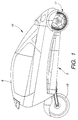
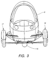
- the ultra-light road vehicle 10 comprises mainly, as shown in Figures 1 to 3, a supporting structure or chassis 9 and an independent passenger compartment or cell 8, mounted on it frame. It is equipped with three wheels distributed in such a way that one 15 is arranged at the rear, substantially in the extension of the chassis, and the two others 17 and 18 at the front, on either side of this chassis. Wheel rear is driven and the front wheels are steered.
- the chassis comprises essentially a hollow central beam 12, produced by means of a profile made of extruded aluminum in the shape of an inverted T, in profiles respective end of which are engaged a rear plate 13 and two front plates 14.
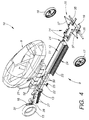
- the rear plate 13 carries the rear wheel 15 of the vehicle 10 and a member suspension spring 16 of this wheel.
- the front plates 14 of the vehicle 10 carry the front wheels 17 and 18 and their suspension, respectively 19 and 20.
- An arch constituting the frame 21 of the adjustable back of a seat, this folder being made of a fabric stretched between the arms of the arch, is also fixed on the central beam. More specifically, the ends of this hoop are provided with two flanges 22 which are respectively engaged in grooves 23 of two side walls 24 of the profile constituting said beam central.
- the locking in position of the flanges 22, and as a result of the arch 21, is carried out by means of spring pins 25, which engage in openings in the grooves 23.
- the rear wheel 15 is mounted on an axle 26 the ends of which are carried by a suspension arm 16 consisting of two suspension arms 27 which define an oscillating support for this wheel.
- the two pivoting arms are articulated on the rear plate 13, at their end opposite to that which carries the axis 26.
- This suspension arm 16 by its design, allows the vehicle to take a normal position and a shortened position which decreases its wheelbase, by the fact that the pivoting arms 27, which carry the wheel 15, are arranged substantially in the extension of the central beam 12 when the vehicle is in its normal position and are inclined relative to this beam when the vehicle is in its position shortened.
- the rear plate 13 also carries an electric motor 28 whose output shaft is fitted with a motor pinion 29 (see FIG. 9) intended to be coupled by a chain or by a belt to a drive sprocket 30 secured to the rear wheel 15.
- the suspension arm 16 comprises a helical spring 31 disposed coaxially around a shock absorber 32 which is mounted between a rigid arm 33 secured to the plate 13 and a rigid support element which will be defined by the continued with reference to Figures 10 and 11.
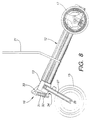
- the front wheels 17 and 18 are connected to the chassis by triangles of suspension integral with the front plate 14, as illustrated more particularly in Figure 6.
- Each wheel is held by a blade lower suspension 35 articulated on a part 36 integral with the plate front 14, and by an upper suspension triangle 37 articulated on an axis 38 held by an appropriate support 39 integral with this same front plate 14.
- Each of the two upper suspension triangles 37 is equipped with a reference 40 arranged obliquely, the two references being interconnected by a shock absorber spring 41 which provides both suspension and damping of the front assembly of the vehicle.
- the lower suspension blade 35 is preferably of the composite type.
- the vehicle is primarily intended for propulsion use electric.
- the source of electrical energy consists of accumulators which are housed inside the central beam 12, on a support sliding in the beam and accessible for example by disassembly of the rear plate.
- Figure 4 shows more particularly the interior of the central beam 12, and in particular a sliding support comprising a set of cells 50 provided in this support and intended to receive a series accumulators 52.
- the accumulators 52 are first deposited in the cells provided for this purpose, then the sliding support is introduced into the central beam by one of its ends, in particular by the rear end, the rear plate 13 being integral with the sliding support 51, and guided in this beam. Thereby, access to accumulators is facilitated by the fact that the sliding support is supported by the rear wheel.
- the cell or cockpit 8 which will be described with reference to FIGS. 12A and 12B is mounted on the central beam 12 by fixing means suitable, in particular by fitting into the grooves 23 of the beam hollow center 12 and by bolting or the like.
- the cell is fixed by four studs which are engaged in the grooves of the central beam. Two of these studs, by example the front studs, are fixed by bolts and two studs, by example the rear studs, are simply held without being fixed. Of this way, the cell expansion and the dimensional changes in length can be easily absorbed.
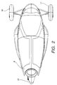
- the cell consists of a carcass of synthetic material, for example of a material which lends itself rotational molding or extrusion blow molding techniques.
- the cell is designed for two places arranged one behind the other. This design provides a well-profiled, aerodynamic cell that promotes the reduction of the coefficient of penetration in the air and by therefore consumption.
- Figures 10 and 11 show more particularly the wheel 15 and the arm rear suspension 16 of the vehicle, seen in perspective when the latter is in the normal position and in the shortened position respectively.
- the rear wheel is carried by the pivoting arms 27 which are articulated on the plate 13, and more exactly on an axis through 60 which carries the electric motor 28, housed in the plate 13.
- This motor is freely mounted on this axis by means of a bearing.
- the carcass of this engine carries a cradle 62, constituting said support element rigid defined above, which serves as a support for the lower end of the spring 31 - shock absorber 32 assembly of the suspension arm 16, of which the upper end is articulated on the rigid arm 33.
- the cradle 62 has two pins 63 which extend laterally from one side and on the other side of its central part. These pins 63 are arranged to cooperate with two hooks 64 articulated on a support 65 mounted on a crosspiece 66 coupled to the two pivoting arms 27.
- the hooks 64 are in taken with the pins 63, so that the suspension, namely the assembly spring 31 - shock absorber 32, is operational, because coupled between the chassis and the suspension arms.
- the mechanical system is advantageous since it only has one minimum of parts and that it puts the shock absorber to contribution, which allows absorb impact against sidewalks or other obstacles.
- the passenger compartment 8 consists of a cell totally independent which can be mounted on the hollow central beam of the vehicle by means of simple bolts.
- This cell is made with plastic parts and is multifunctional, ensuring both exterior body with elements such as headlight brackets and signal lights, and the interior cabin by integrating the edge, acoustic insulation and seat in particular.
- the sectional view 12A shows the general shape of the cell which incorporates the dashboard 80 and carries a windshield 81.
- the sectional view 12B shows a lower part 82 and an upper part 83 which are constructed in double thickness with integrated air bags 84, 85.
- Lateral uprights 87 which partially carry the windshield, the rear end 86 of the airframe and the floor 88 advantageously also have hollow zones which constitute air cushions and also generate a reduction in the cell.
- the cell or cockpit 8 advantageously consists of several pieces, for example three partially hollow pieces to form air cushions to absorb shocks. These pieces are preferably welded together to form reinforcement zones along the solders.
- the cell can detach from the chassis by breaking the studs following a high stress, especially in the event of an impact. Thanks to the presence of air cushions that constitute shock absorbers, the cell can become a survival cabin with a lower energy to dissipate than that of the rest of the vehicle comprising the chassis, the wheels, the engine, etc.
- the cell advantageously has lateral protrusions serving as step and also constituting absorbers of kinetic energy in the event of an impact, in particular thanks to their particular shape.
- This construction provides excellent passenger protection in the event of shock.
- the cell molded in a hollow body can constitute a light diffuser thanks to several sources distributed in the body to illuminate all or part of the vehicle at night.
- the vehicle according to the invention is particularly advantageous for various reasons.
- all the main components are easily removable and their replacement in case of damage can be done without significant costs.
- Assembly is simple and only uses equipment not requiring large investments for the assembly.
- the wheel suspensions are articulated on the plates corresponding, which allows the realization of pre-assembled sub-assemblies. These plates are embedded and fixed by means of bolts to the beam hollow center.
- This assembly method allows the realization of the vehicle according to the invention without going through the usual heavy infrastructures of automobile industry.
- the assembly amounts to assembling pre-assembled modules, which allows in particular the creation of small assembly units close to sales and use sites.
Landscapes
- Engineering & Computer Science (AREA)
- Chemical & Material Sciences (AREA)
- Combustion & Propulsion (AREA)
- Transportation (AREA)
- Mechanical Engineering (AREA)
- Body Structure For Vehicles (AREA)
- Lighting Device Outwards From Vehicle And Optical Signal (AREA)
- Non-Portable Lighting Devices Or Systems Thereof (AREA)
- Arrangement Or Mounting Of Propulsion Units For Vehicles (AREA)
- Glass Compositions (AREA)
- Vehicle Body Suspensions (AREA)
- Automatic Cycles, And Cycles In General (AREA)
Claims (25)
- Ultraleichtes Straßenfahrzeug, das nur eine geringe Anzahl von Bauteilen umfaßt, insbesondere ein Fahrzeug vom Typ des sogenanntenStadtautos" für Pendelzwecke, insbesondere mit elektrischem Antrieb, bestehend aus einer Tragestruktur, zwei Vorderrädern und einem Hinterrad, die mit Hilfe von Aufhängungen auf dieser Tragestruktur montiert sind, und einem unabhängigen Karosseriegehäuse, das an diese Tragestruktur angepaßt ist, wobei die Tragestruktur einen hohlen Mittelträger umfaßt, dadurch gekennzeichnet, daß der hohle Mittelträger (12) von einem extrudierten Profil mit einem konstanten Querschnitt aus einem leichten Material gebildet wird, daß die beiden Vorderräder (17, 18) führend sind und das Hinterrad (15) antreibend und im wesentlichen in der Verlängerung des Mittelträgers (12) angeordnet ist, daß der Antriebsmotor (28) sowie eine Energiereserve im Inneren des hohlen Mittelträgers (12) angeordnet sind und daß das unabhängige Karosseriegehäuse zur Gänze an dem hohlen Mittelträger (12) befestigt ist.

- Fahrzeug nach Anspruch 1, dadurch gekennzeichnet, daß es zwei Frontplatten (14) und eine Hinterplatte (13) umfaßt, wobei diese Platten derart angeordnet sind, daß sie zumindest teilweise in Endprofile des hohlen Mittelträgers eingreifen, und daß diese Platten derart angepaßt sind, daß sie die Aufhängungen der Vorderräder (17, 18) bzw. die Aufhängung des Hinterrades (15) tragen.
- Fahrzeug nach Anspruch 1, dadurch gekennzeichnet, daß der hohle Mittelträger (12) auf seiner gesamten Länge ein Profil eines umgekehrten T aufweist, dessen Innenseite seitlich von zwei Seitenwandungen (24) verlängert ist, die symmetrisch in bezug zu einer mittleren Längsebene, die durch diesen Träger geht, angeordnet sind.
- Fahrzeug nach Anspruch 3, dadurch gekennzeichnet, daß die Seitenwandungen (24) jeweils mindestens eine Längsrille (23) umfassen, die derart angeordnet ist, daß sie Bauteile und/oder Zubehörteile befestigt.
- Fahrzeug nach Anspruch 2, dadurch gekennzeichnet, daß die Hinterplatte (13) eine Stütze für das Hinterrad trägt, wobei diese Stütze ein Tragfederelement (16) und zwei Aufhängungsarme (27) umfaßt, von denen ein Ende durch eine Achse an dieser Platte befestigt ist und das andere Ende die Achse (26) des Hinterrades (15) trägt, wobei letztgenanntes zwischen dem Aufhängungsarm angeordnet ist.
- Fahrzeug nach Anspruch 5, dadurch gekennzeichnet, daß die Hinterplatte (13) ein Ende eines Tragfederelements (16) trägt, wobei das andere Ende mit den Aufhängungsarmen (27) des Hinterrades verbunden ist.
- Fahrzeug nach Anspruch 5, dadurch gekennzeichnet, daß der Aufhängungsarm des Hinterrades (15) derart angeordnet ist, daß er es dem Fahrzeug ermöglicht, eine normale und eine verkürzte Position einzunehmen, wobei die Schwenkteile (27), die das Rad tragen, im wesentlichen in der Verlängerung des Mittelträgers (12) angeordnet sind, wenn sich das Fahrzeug in seiner normalen Position befindet, und diese Teile in bezug zu diesem Mittelträger geneigt sind, wenn sich das Fahrzeug in seiner verkürzten Position befindet, wobei diese verkürzte Position durch den Antrieb des antreibenden Hinterrades und die gleichzeitige Blockierung der führenden Vorderräder erreicht wird.
- Fahrzeug nach Anspruch 5, dadurch gekennzeichnet, daß die Schwenkteile (27) auf der Hinterplatte (13) gelenkig angeordnet und auf einer Querachse (60) montiert sind, die einen Elektromotor (28) trägt, auf dessen Gehäuse ein Schlitten (62) montiert ist, der das untere Ende einer Feder (31) - Dämpfer (32) - Einheit des Aufhängungsarmes (16) trägt, dessen oberes Ende an einem Arm (33) befestigt ist, der mit der Hinterplatte (13) verbunden ist.
- Fahrzeug nach Anspruch 8, dadurch gekennzeichnet, daß der Schlitten (62) zwei Stifte (63) umfaßt, die sich seitlich auf beiden Seiten dieses Schlittens erstrecken und die derart angeordnet sind, daß sie mit zwei Haken (64) zusammenwirken, um das Fahrzeug in seiner Normalposition zu verriegeln.
- Fahrzeug nach Anspruch 9, dadurch gekennzeichnet, daß die Haken (64) schwenkbar und auf einer Stütze (65) gelenkig montiert sind, die von einer Querstrebe (66) getragen wird, die mit zwei Schwenkteilen (27) gekoppelt ist.
- Fahrzeug nach Anspruch 8, dadurch gekennzeichnet, daß es einen blockierenden Zylinder (67) umfaßt, der derart angeordnet ist, daß er das Fahrzeug in seiner verkürzten Position hält.
- Fahrzeug nach Anspruch 11, dadurch gekennzeichnet, daß der blockierende Zylinder (67) zwischen dem Motor (28) und der Querstrebe (66) angeordnet ist, die die Haken (64) trägt.
- Fahrzeug nach Anspruch 4, dadurch gekennzeichnet, daß es einen Bogen (21) umfaßt, der einen Sitzbeschlag bildet, wobei die Enden dieses Bogens mit zwei Flanschen (22) versehen sind, die jeweils in die Längsrillen (23) eingreifen.
- Fahrzeug nach Anspruch 1, dadurch gekennzeichnet, daß der hohle Mittelträger (12) eine gleitende Stütze umfaßt, um mindestens einen Akkumulator (52) zur Versorgung des elektrischen Antriebsmotors (28) zu enthalten.
- Fahrzeug nach Anspruch 1; dadurch gekennzeichnet, daß das Karosseriegehäuse (8) eine unabhängige Zelle aus synthetischem Material ist, von der mindestens ein Teil der Wandungen verdoppelt ist und Luftpolster enthält.
- Fahrzeug nach Anspruch 15, dadurch gekennzeichnet, daß das Karosseriegehäuse (8) zumindest teilweise nach einer Technik des Rotationsformens, des Formens von Hohlkörpern oder des Extrusionsblasens hergestellt wird.
- Fahrzeug nach Anspruch 15, dadurch gekennzeichnet, daß das Karosseriegehäuse (8) auf dem hohlen Mittelträger (12) mit Hilfe von Kontaktstiften, die in die Rillen (23) eingreifen, montiert ist.
- Fahrzeug nach Anspruch 17, dadurch gekennzeichnet, daß die Kontaktstifte in der Anzahl zu vier Stück vorhanden sind, wobei zwei Kontaktstifte, die auf beiden Seiten der Achse des hohlen Mittelträgers (12) angeordnet sind, fest sind und die beiden anderen in den Rillen (23) gleitend sind.
- Fahrzeug nach Anspruch 1, dadurch gekennzeichnet, daß der hohle Mittelträger (12) eine gleitende Stütze (51) umfaßt, die mindestens eine Akkumulatorbatterie (52) für die Versorgung des Elektromotors (28) umfaßt.
- Fahrzeug nach Anspruch 19, dadurch gekennzeichnet, daß die gleitende Stütze (51) mit der Hinterplatte verbunden ist.
- Fahrzeug nach Anspruch 1, dadurch gekennzeichnet, daß der extrudierte, an beiden Enden geschlossene, hohle Mittelträger (12) einen Treibstoffbehälter für einen Thermomotor bildet.
- Fahrzeug nach Anspruch 15, dadurch gekennzeichnet, daß das Karosseriegehäuse (8) mehrere verschweißte Elemente umfaßt, wobei die Schweißnähte Verstärkungszonen darstellen.
- Fahrzeug nach Anspruch 15, dadurch gekennzeichnet, daß das Karosseriegehäuse (8) einen Überlebenshohlraum bildet, der mit dem hohlen Mittelträger (12) durch abnehmbare Kontaktstifte im Falle eines Aufpralls verbunden ist.
- Fahrzeug nach Anspruch 15, dadurch gekennzeichnet, daß das Karosseriegehäuse (8) seitliche Ausstülpungen umfaßt, um ein Trittbrett und einen Energieaufnehmer zu bilden.
- Fahrzeug nach Anspruch 15, dadurch gekennzeichnet, daß das Karosseriegehäuse (8), das zu einem Hohlkörper geformt ist, Mittel zur Verbreitung des Lichtes, das aus mindestens einer Lichtquelle kommt, umfaßt.
Applications Claiming Priority (3)
| Application Number | Priority Date | Filing Date | Title |
|---|---|---|---|
| FR9512951A FR2740092B1 (fr) | 1995-10-23 | 1995-10-23 | Vehicule routier ultra-leger |
| FR9512951 | 1995-10-23 | ||
| PCT/CH1996/000371 WO1997015484A1 (fr) | 1995-10-23 | 1996-10-22 | Vehicule routier ultra-leger |
Publications (2)
| Publication Number | Publication Date |
|---|---|
| EP0854818A1 EP0854818A1 (de) | 1998-07-29 |
| EP0854818B1 true EP0854818B1 (de) | 1999-06-16 |
Family
ID=9484167
Family Applications (1)
| Application Number | Title | Priority Date | Filing Date |
|---|---|---|---|
| EP96933304A Expired - Lifetime EP0854818B1 (de) | 1995-10-23 | 1996-10-22 | Ultraleichtes strassenfahrzeug |
Country Status (11)
| Country | Link |
|---|---|
| US (1) | US6015022A (de) |
| EP (1) | EP0854818B1 (de) |
| JP (1) | JPH11514948A (de) |
| AT (1) | ATE181297T1 (de) |
| AU (1) | AU7209596A (de) |
| CA (1) | CA2235498C (de) |
| DE (1) | DE69602964T2 (de) |
| ES (1) | ES2134641T3 (de) |
| FR (1) | FR2740092B1 (de) |
| NO (1) | NO311878B1 (de) |
| WO (1) | WO1997015484A1 (de) |
Cited By (2)
| Publication number | Priority date | Publication date | Assignee | Title |
|---|---|---|---|---|
| DE102011001861A1 (de) | 2011-04-07 | 2012-10-11 | Dr. Ing. H.C. F. Porsche Ag | Tragstruktur für ein Kraftfahrzeug |
| WO2016135691A3 (fr) * | 2015-02-28 | 2016-10-20 | Aventor Sa | Véhicule monoplace électrique |
Families Citing this family (91)
| Publication number | Priority date | Publication date | Assignee | Title |
|---|---|---|---|---|
| SE515283C2 (sv) * | 1999-04-15 | 2001-07-09 | Scania Cv Abp | Fordonsram för tunga fordon samt förfarande för tillverkning av en fordonsram |
| US20020079153A1 (en) * | 2000-10-07 | 2002-06-27 | Durand Robert D. | Vehicular frame assembly including hollow frame member that houses electrical battery |
| USD449018S1 (en) | 2000-12-22 | 2001-10-09 | Knusaga Corporation | Three wheeled motorized vehicle |
| US6464030B1 (en) * | 2001-04-17 | 2002-10-15 | Corbin Pacific, Inc. | Three wheel steering assembly |
| US20040129483A1 (en) * | 2001-06-11 | 2004-07-08 | Bruno Girouard | Vehicle and adjustable steering shaft therefor |
| US20040035626A1 (en) * | 2002-02-22 | 2004-02-26 | Bruno Girouard | Vehicle and adjustable steering shaft therefor |
| DE10202957A1 (de) * | 2002-01-26 | 2003-08-07 | Porsche Ag | Aufbau für Kraftfahrzeuge |
| US6948581B2 (en) * | 2002-02-22 | 2005-09-27 | Bombardier Recreational Products Inc | Three-wheel vehicle and concentric intermediate sprocket assembly therefor |
| US20040129473A1 (en) * | 2002-02-22 | 2004-07-08 | Jean-Guy Talbot | Ergonomic arrangement for a three-wheeled vehicle |
| US20030221890A1 (en) * | 2002-02-22 | 2003-12-04 | Berthold Fecteau | Three-wheeled vehicle with a continuously variable transmission |
| US20040035623A1 (en) * | 2002-02-22 | 2004-02-26 | Berthold Fecteau | Frame configuration for a three-wheel vehicle |
| US20030221891A1 (en) * | 2002-02-22 | 2003-12-04 | Berthold Fecteau | Three-wheeled vehicle with a fender assembly and lighting system therefor |
| US20040032120A1 (en) * | 2002-02-22 | 2004-02-19 | Esa Vaisanen | Progressive steering system |
| US20040035625A1 (en) * | 2002-02-22 | 2004-02-26 | Jean-Guy Talbot | Ergonomic arrangement for a three-wheeled vehicle |
| USD485788S1 (en) | 2002-02-23 | 2004-01-27 | Bombardier Inc. | Three-wheeled vehicle |
| FR2841196A1 (fr) * | 2002-06-19 | 2003-12-26 | Jean Francois Vincent | Isolation thermique et phonique de la carosserie d'un vehicule a moteur |
| FR2848152B1 (fr) * | 2002-12-10 | 2005-02-18 | Hugues Escarguel | Vehicule a pedales, a trois ou quatre roues |
| EP1863696A4 (de) * | 2005-03-16 | 2009-05-06 | Hoppenstein Reuben M D | Weiterentwicklungen des verbesserten fahrzeugchassis |
| US7131666B1 (en) * | 2005-06-16 | 2006-11-07 | Empire Welding & Fabricating, Inc. | Off-road vehicle trailer |
| FR2899197B1 (fr) * | 2006-04-04 | 2009-03-20 | Jean Naud | Habitacle de vehicule a ouverture adaptable |
| US8141890B2 (en) * | 2006-04-26 | 2012-03-27 | Vectrix International Limited | Vehicle with lockable tilt system |
| US8496268B2 (en) | 2008-01-24 | 2013-07-30 | Theodore & Associates Llc | Universal chassis |
| US20080179870A1 (en) * | 2007-01-26 | 2008-07-31 | Theodore & Associates Llc | Universal chassis |
| US9045163B2 (en) | 2007-01-26 | 2015-06-02 | Theodore & Associates | Universal chassis apparatus for automotive vehicle |
| DE102008036870A1 (de) * | 2008-08-07 | 2010-02-11 | Dr. Ing. H.C. F. Porsche Aktiengesellschaft | Fahrzeugaufbau |
| US7661501B1 (en) | 2008-09-16 | 2010-02-16 | Joab Jay Perdue | Vehicle operated by multiple power sources |
| GB2465600A (en) * | 2008-11-22 | 2010-05-26 | Charles Geoffrey Bazeley | A motor vehicle of ovoid or tapered shape |
| GB2468487B (en) * | 2009-03-09 | 2013-05-01 | Nissan Motor Mfg Uk Ltd | Vehicle suspension |
| US20100230192A1 (en) * | 2009-03-12 | 2010-09-16 | Riley Robert Q | Hybrid vehicle |
| DE202009004287U1 (de) | 2009-04-01 | 2009-06-10 | Hs Genion Gmbh | Fahrzeug |
| DE102009030631A1 (de) * | 2009-06-25 | 2011-01-05 | Benteler Automobiltechnik Gmbh | Kraftfahrzeug |
| FR2947798B1 (fr) * | 2009-07-10 | 2012-11-16 | Peugeot Citroen Automobiles Sa | Vehicule automobile dont les montants avant des cotes d'habitacle sont inclines vers l'avant |
| CN101698420A (zh) * | 2009-09-18 | 2010-04-28 | 郝明刚 | 三角智动变形机动车 |
| DE102009048573A1 (de) * | 2009-10-07 | 2011-04-14 | Bayerische Motoren Werke Aktiengesellschaft | Kraftfahrzeug, insbesondere Dreirad |
| CN201670271U (zh) * | 2010-04-19 | 2010-12-15 | 鲍文光 | 一种承载式超微型低速纯电动汽车车身 |
| US20110272906A1 (en) * | 2010-05-05 | 2011-11-10 | Hall David R | Swingarm Suspension |
| CN102009692B (zh) * | 2010-06-13 | 2012-07-04 | 张越平 | 用于混合动力或纯电动汽车的车架底盘结构 |
| DE102011078265B3 (de) | 2011-06-29 | 2012-06-21 | Bayerische Motoren Werke Aktiengesellschaft | Fahrzeug mit einem als tragende Strukturkomponente ausgebildeten Gehäuse eines elektrischen Energiespeichers |
| EP2767464B1 (de) * | 2011-10-06 | 2019-11-06 | Yamaha Hatsudoki Kabushiki Kaisha | Elektrofahrzeug |
| USD678124S1 (en) * | 2011-10-31 | 2013-03-19 | Tanom Motors, LLC | Reverse trike |
| WO2013066804A1 (en) | 2011-10-31 | 2013-05-10 | Tanom Motors, LLC | Systems and apparatus for a three-wheeled vehicle |
| USD682158S1 (en) | 2011-10-31 | 2013-05-14 | Tanom Motors, LLC | Reverse trike |
| ES1078070Y (es) * | 2012-11-02 | 2013-02-15 | Aloy Jordi Nadal | Estructura para la construcción de un chasis de un vehículo, remolque o similar |
| US20150329173A1 (en) * | 2012-12-21 | 2015-11-19 | Recticel N.V. | Human Powered Land Vehicle |
| WO2014123489A1 (en) * | 2013-02-05 | 2014-08-14 | Piponeer S.R.O. | Ultralight three-track urban vehicle |
| JP5441044B1 (ja) * | 2013-02-08 | 2014-03-12 | サーチウェア株式会社 | 小型車両 |
| USD871258S1 (en) * | 2013-03-01 | 2019-12-31 | Organic Transit, Inc. | Hybrid pedal and electric powered vehicle |
| WO2014140412A1 (en) * | 2013-03-14 | 2014-09-18 | Valmet Automotive Oy | Base frame for an energy storage of a vehicle |
| CN105143027B (zh) * | 2013-03-15 | 2019-05-31 | D·凯利 | 三轮车辆 |
| US8840131B1 (en) * | 2013-03-15 | 2014-09-23 | Planet Rider LLC | Three-wheeled vehicle |
| US9493191B2 (en) * | 2013-04-15 | 2016-11-15 | Stephen Kariniemi | Arcuate frame for a vehicle |
| EP3012175B1 (de) * | 2013-06-21 | 2019-02-13 | Teijin Limited | Fahrzeug mit selbsttragender konstruktion aus thermoplastischen kunstharzelementen |
| CN103407518B (zh) * | 2013-08-23 | 2016-06-01 | 王坦坤 | 车辆自动倾斜平衡控制系统及具有该系统的倒三轮车 |
| USD723978S1 (en) * | 2013-09-23 | 2015-03-10 | Toyota Jidosha Kabushiki Kaisha | Motor vehicle and/or toy replica thereof |
| US9188198B2 (en) | 2013-10-28 | 2015-11-17 | Tanom Motors, LLC | Drive train and systems for a three-wheeled vehicle |
| USD774945S1 (en) * | 2014-02-17 | 2016-12-27 | Trefor A/S | Motor scooter |
| DE102014215979A1 (de) * | 2014-08-12 | 2016-02-18 | Volkswagen Aktiengesellschaft | Kraftfahrzeug |
| JP2018528901A (ja) * | 2015-07-15 | 2018-10-04 | ゲーイ4 エス.エル.オーGi4 S.R.O | 電気回転モータが組み込まれた動力車両本体の中央負荷伝達管の構成、その組立方法、およびその使用方法 |
| USD788648S1 (en) * | 2015-08-18 | 2017-06-06 | Bombardier Recreational Products Inc. | Three-wheeled vehicle |
| USD824805S1 (en) * | 2015-08-19 | 2018-08-07 | Kerv Automotive N.V. | Three-wheeled vehicle |
| USD777060S1 (en) * | 2015-09-15 | 2017-01-24 | Michael W. Hanagan | Motor vehicle exterior |
| JP1543913S (de) * | 2015-09-30 | 2016-02-15 | ||
| DK3393889T3 (da) * | 2015-12-24 | 2022-12-12 | Softcar Sa | Køretøjsarkitektur |
| USD842758S1 (en) * | 2016-02-16 | 2019-03-12 | Hall Labs Llc | Reverse trike roadster |
| USD817228S1 (en) * | 2016-05-09 | 2018-05-08 | Electrameccanica Vehicles Corp | Reverse trike vehicle |
| AT15470U1 (de) * | 2016-06-17 | 2017-09-15 | Inst Für Fahrzeugtechnik Technische Universität Graz | Mechanismus und Verfahren zur Variation des Achsabstandes eines Fahrzeuges |
| USD883142S1 (en) * | 2016-06-24 | 2020-05-05 | Hall Labs Llc | Reverse trike vehicle |
| CN106741292A (zh) * | 2016-12-23 | 2017-05-31 | 东莞产权交易中心 | 一种单人驾驶小车 |
| FR3062110B1 (fr) * | 2017-01-25 | 2022-05-20 | Beller Jean Marc | Tricycle electrique monoplace |
| US9914492B1 (en) | 2017-04-13 | 2018-03-13 | Toyota Research Institute, Inc. | Low-profile vehicle |
| USD872354S1 (en) | 2017-09-20 | 2020-01-07 | Bombardier Recreational Products Inc. | Set of vehicle headlight covers |
| CA180376S (en) | 2017-09-20 | 2019-05-29 | Bombardier Recreational Products Inc | Vehicle body |
| USD873711S1 (en) * | 2017-11-20 | 2020-01-28 | Hall Labs Llc | Reverse trike roadster |
| USD873712S1 (en) * | 2017-12-07 | 2020-01-28 | Hall Labs Llc | Reverse trike roadster |
| USD861538S1 (en) * | 2018-02-02 | 2019-10-01 | Stintum Holding B.V. | Motor scooter |
| USD874361S1 (en) | 2018-03-20 | 2020-02-04 | Bombardier Recreational Products Inc. | Grille surround for a vehicle |
| USD860488S1 (en) | 2018-03-20 | 2019-09-17 | Bombardier Recreational Products Inc. | Headlight |
| USD858350S1 (en) | 2018-03-20 | 2019-09-03 | Bombardier Recreational Products Inc. | Vehicle rear module |
| USD874975S1 (en) * | 2018-06-15 | 2020-02-11 | Ayro, Inc. | Electric vehicle |
| USD874976S1 (en) * | 2018-06-15 | 2020-02-11 | Ayro, Inc. | Electric vehicle |
| US10569641B1 (en) * | 2018-08-07 | 2020-02-25 | Anthony L. Brewer | Multi-passenger electric transporter |
| USD886676S1 (en) * | 2018-10-17 | 2020-06-09 | Hall Labs Llc | Three wheeled single-passenger roadster |
| USD886677S1 (en) * | 2018-10-26 | 2020-06-09 | Hall Labs Llc | Three-wheeled roadster |
| USD909242S1 (en) * | 2019-05-28 | 2021-02-02 | Eric Brandon | Three-wheeled vehicle |
| EP4005910A4 (de) | 2019-08-30 | 2022-09-28 | Yamaha Hatsudoki Kabushiki Kaisha | Neigefahrzeug |
| WO2021039990A1 (ja) * | 2019-08-30 | 2021-03-04 | ヤマハ発動機株式会社 | リーン車両 |
| USD973542S1 (en) * | 2021-03-22 | 2022-12-27 | EMC Squared Vehicles LLC | Three-wheeled delivery vehicle |
| WO2023228125A1 (fr) * | 2022-05-25 | 2023-11-30 | Softcar Sa | Véhicule tracteur solaire tous terrains à modules interchangeables |
| US12377693B2 (en) | 2022-09-01 | 2025-08-05 | Aptera Motors Corp. | Rear suspension for vehicle having improved swing arm |
| USD1006679S1 (en) * | 2022-09-19 | 2023-12-05 | Anhui Yadea Locomotive Co., Ltd. | Electric reverse trike |
| USD1058433S1 (en) * | 2023-05-05 | 2025-01-21 | John C. Hickey | Aerodynamic lightweight electric vehicle |
Family Cites Families (9)
| Publication number | Priority date | Publication date | Assignee | Title |
|---|---|---|---|---|
| US1989995A (en) * | 1930-02-26 | 1935-02-05 | James V Martin | Autoette |
| US2383611A (en) * | 1944-09-04 | 1945-08-28 | John P Marcy | Motor vehicle |
| WO1981000088A1 (en) * | 1979-06-29 | 1981-01-22 | E Jephcott | Ultra narrow enclosed motor vehicles |
| DE3027072A1 (de) * | 1980-07-17 | 1982-03-18 | Florian Dipl.-Ing. 7989 Haslach Windischbauer | Dreiradfahrzeug |
| ZA811127B (en) * | 1981-02-20 | 1983-01-26 | William John Badsey | Land vehicle |
| US4506753A (en) * | 1981-06-12 | 1985-03-26 | Wood Jr David D | Removeable forecab for motorcycles |
| FR2687352B1 (fr) * | 1992-02-17 | 1995-01-06 | Paul Bourrieres | Voiture electrique a usage polyvalent. |
| FR2694240B1 (fr) * | 1992-07-30 | 1994-10-07 | Matra Automobile | Véhicule automobile à empattement variable. |
| DE4243455A1 (de) * | 1992-12-22 | 1994-06-23 | Berghauer Bgh Service Gmbh | Grundeinheit für ein Kraftfahrzeug |
-
1995
- 1995-10-23 FR FR9512951A patent/FR2740092B1/fr not_active Expired - Fee Related
-
1996
- 1996-10-22 CA CA002235498A patent/CA2235498C/fr not_active Expired - Fee Related
- 1996-10-22 ES ES96933304T patent/ES2134641T3/es not_active Expired - Lifetime
- 1996-10-22 JP JP9516168A patent/JPH11514948A/ja not_active Ceased
- 1996-10-22 EP EP96933304A patent/EP0854818B1/de not_active Expired - Lifetime
- 1996-10-22 WO PCT/CH1996/000371 patent/WO1997015484A1/fr not_active Ceased
- 1996-10-22 AU AU72095/96A patent/AU7209596A/en not_active Abandoned
- 1996-10-22 AT AT96933304T patent/ATE181297T1/de not_active IP Right Cessation
- 1996-10-22 US US09/043,099 patent/US6015022A/en not_active Expired - Lifetime
- 1996-10-22 DE DE69602964T patent/DE69602964T2/de not_active Expired - Lifetime
-
1998
- 1998-04-22 NO NO19981806A patent/NO311878B1/no not_active IP Right Cessation
Cited By (4)
| Publication number | Priority date | Publication date | Assignee | Title |
|---|---|---|---|---|
| DE102011001861A1 (de) | 2011-04-07 | 2012-10-11 | Dr. Ing. H.C. F. Porsche Ag | Tragstruktur für ein Kraftfahrzeug |
| DE102011001861B4 (de) | 2011-04-07 | 2024-12-05 | Dr. Ing. H.C. F. Porsche Ag | Tragstruktur für ein Kraftfahrzeug und Kraftfahrzeug |
| WO2016135691A3 (fr) * | 2015-02-28 | 2016-10-20 | Aventor Sa | Véhicule monoplace électrique |
| EP3261867B1 (de) * | 2015-02-28 | 2021-10-06 | Aventor SA | Elektrisches einsitzerfahrzeug |
Also Published As
| Publication number | Publication date |
|---|---|
| MX9803251A (es) | 1998-09-30 |
| WO1997015484A1 (fr) | 1997-05-01 |
| NO311878B1 (no) | 2002-02-11 |
| NO981806D0 (no) | 1998-04-22 |
| FR2740092B1 (fr) | 1998-01-02 |
| ES2134641T3 (es) | 1999-10-01 |
| JPH11514948A (ja) | 1999-12-21 |
| EP0854818A1 (de) | 1998-07-29 |
| NO981806L (no) | 1998-06-23 |
| DE69602964D1 (de) | 1999-07-22 |
| AU7209596A (en) | 1997-05-15 |
| ATE181297T1 (de) | 1999-07-15 |
| CA2235498C (fr) | 2005-02-15 |
| US6015022A (en) | 2000-01-18 |
| CA2235498A1 (fr) | 1997-05-01 |
| FR2740092A1 (fr) | 1997-04-25 |
| DE69602964T2 (de) | 2000-02-03 |
Similar Documents
| Publication | Publication Date | Title |
|---|---|---|
| EP0854818B1 (de) | Ultraleichtes strassenfahrzeug | |
| EP1874613B1 (de) | Fondboden eines automobils | |
| EP3186135A1 (de) | Landfahrzeug mit flüssigkeitsdichter schale für stromversorgungseinheit und zugehöriges herstellungsverfahren | |
| FR2936189A1 (fr) | M0dule de stockage et vehicule comprenant un tel module | |
| EP1343677A1 (de) | Plattformfahrzeugzentralrahmen in sandwichbauweise; vorderer und hinterer gitterrahmen mit daran befestigten linearstossdämpfern | |
| FR3001185A1 (fr) | Vehicule terrestre et procede de fabrication d'un tel vehicule | |
| EP2532547B1 (de) | Fahrgestellstruktur zur Aufnahme eines Fahrzeuginnenraums eines Kraftfahrzeugs mit Elektroantrieb, und mit einer solchen Fahrgestellstruktur ausgestattetes Kraftfahrzeug | |
| FR2844766A1 (fr) | Vehicule automobile | |
| FR2922179A1 (fr) | Structure de caisse de vehicule automobile et vehicule comportant une telle structure de caisse. | |
| FR2977559A1 (fr) | Vehicule automobile a deux roues et a structure porteuse et protectrice | |
| EP2928759B1 (de) | Boden und selbsttragender rahmen für ein fahrzeug | |
| FR3160376A1 (fr) | Longeron de véhicule automobile renforcé et ensemble de soubassement comportant un tel longeron | |
| FR2947797A1 (fr) | Vehicule dont le chassis comprend au moins deux structures axiales | |
| FR3144066A1 (fr) | Châssis pour un véhicule comprenant un réservoir | |
| WO2001062580A1 (fr) | Vehicule motorise leger a deux roues carene | |
| FR3141135A1 (fr) | Structure de véhicule automobile compact | |
| EP4638244A1 (de) | Tank für ein fahrzeug | |
| FR3167119A1 (fr) | Structure avec appui façade avant de véhicule automobile | |
| WO2024156960A1 (fr) | Structure arrière renforcée de caisse pour véhicule automobile | |
| FR3138644A1 (fr) | Structure de véhicule automobile avec plancher de chargement | |
| FR2873335A1 (fr) | Vehicule motorise leger | |
| WO2024170785A1 (fr) | Structure de véhicule automobile en matériaux composites et véhicule ainsi obtenu | |
| EP4355640A1 (de) | Hybrid- oder elektromotorfahrzeug mit einer vorrichtung zum schutz der antriebsbatterie | |
| FR2772333A1 (fr) | Vehicule automobile comportant un chassis tubulaire | |
| FR3028478A1 (fr) | Structure de caisse comprenant un element de renfort |
Legal Events
| Date | Code | Title | Description |
|---|---|---|---|
| PUAI | Public reference made under article 153(3) epc to a published international application that has entered the european phase |
Free format text: ORIGINAL CODE: 0009012 |
|
| 17P | Request for examination filed |
Effective date: 19980512 |
|
| AK | Designated contracting states |
Kind code of ref document: A1 Designated state(s): AT BE CH DE DK ES FI FR GB GR IE IT LI LU MC NL PT SE |
|
| GRAG | Despatch of communication of intention to grant |
Free format text: ORIGINAL CODE: EPIDOS AGRA |
|
| GRAG | Despatch of communication of intention to grant |
Free format text: ORIGINAL CODE: EPIDOS AGRA |
|
| GRAH | Despatch of communication of intention to grant a patent |
Free format text: ORIGINAL CODE: EPIDOS IGRA |
|
| 17Q | First examination report despatched |
Effective date: 19981202 |
|
| GRAH | Despatch of communication of intention to grant a patent |
Free format text: ORIGINAL CODE: EPIDOS IGRA |
|
| GRAA | (expected) grant |
Free format text: ORIGINAL CODE: 0009210 |
|
| AK | Designated contracting states |
Kind code of ref document: B1 Designated state(s): AT BE CH DE DK ES FI FR GB GR IE IT LI LU MC NL PT SE |
|
| PG25 | Lapsed in a contracting state [announced via postgrant information from national office to epo] |
Ref country code: SE Free format text: THE PATENT HAS BEEN ANNULLED BY A DECISION OF A NATIONAL AUTHORITY Effective date: 19990616 Ref country code: GR Free format text: LAPSE BECAUSE OF NON-PAYMENT OF DUE FEES Effective date: 19990616 Ref country code: GB Free format text: LAPSE BECAUSE OF FAILURE TO SUBMIT A TRANSLATION OF THE DESCRIPTION OR TO PAY THE FEE WITHIN THE PRESCRIBED TIME-LIMIT Effective date: 19990616 Ref country code: FI Free format text: LAPSE BECAUSE OF NON-PAYMENT OF DUE FEES Effective date: 19990616 Ref country code: AT Free format text: LAPSE BECAUSE OF FAILURE TO SUBMIT A TRANSLATION OF THE DESCRIPTION OR TO PAY THE FEE WITHIN THE PRESCRIBED TIME-LIMIT Effective date: 19990616 |
|
| REF | Corresponds to: |
Ref document number: 181297 Country of ref document: AT Date of ref document: 19990715 Kind code of ref document: T |
|
| REG | Reference to a national code |
Ref country code: CH Ref legal event code: EP |
|
| REF | Corresponds to: |
Ref document number: 69602964 Country of ref document: DE Date of ref document: 19990722 |
|
| REG | Reference to a national code |
Ref country code: CH Ref legal event code: NV Representative=s name: CABINET ROLAND NITHARDT CONSEILS EN PROPRIETE INDU |
|
| REG | Reference to a national code |
Ref country code: IE Ref legal event code: FG4D Free format text: FRENCH |
|
| ITF | It: translation for a ep patent filed | ||
| PG25 | Lapsed in a contracting state [announced via postgrant information from national office to epo] |
Ref country code: PT Free format text: LAPSE BECAUSE OF FAILURE TO SUBMIT A TRANSLATION OF THE DESCRIPTION OR TO PAY THE FEE WITHIN THE PRESCRIBED TIME-LIMIT Effective date: 19990916 Ref country code: DK Free format text: LAPSE BECAUSE OF FAILURE TO SUBMIT A TRANSLATION OF THE DESCRIPTION OR TO PAY THE FEE WITHIN THE PRESCRIBED TIME-LIMIT Effective date: 19990916 |
|
| REG | Reference to a national code |
Ref country code: ES Ref legal event code: FG2A Ref document number: 2134641 Country of ref document: ES Kind code of ref document: T3 |
|
| PG25 | Lapsed in a contracting state [announced via postgrant information from national office to epo] |
Ref country code: IE Free format text: LAPSE BECAUSE OF NON-PAYMENT OF DUE FEES Effective date: 19991022 |
|
| GBV | Gb: ep patent (uk) treated as always having been void in accordance with gb section 77(7)/1977 [no translation filed] |
Effective date: 19990616 |
|
| PLBE | No opposition filed within time limit |
Free format text: ORIGINAL CODE: 0009261 |
|
| STAA | Information on the status of an ep patent application or granted ep patent |
Free format text: STATUS: NO OPPOSITION FILED WITHIN TIME LIMIT |
|
| PG25 | Lapsed in a contracting state [announced via postgrant information from national office to epo] |
Ref country code: MC Free format text: LAPSE BECAUSE OF NON-PAYMENT OF DUE FEES Effective date: 20000430 |
|
| 26N | No opposition filed | ||
| REG | Reference to a national code |
Ref country code: IE Ref legal event code: MM4A |
|
| REG | Reference to a national code |
Ref country code: CH Ref legal event code: PUE Owner name: FREHNER MARC Free format text: THULIEZ, JEAN-LUC#MONTAGU 30#2520 LA NEUVEVILLE (CH) -TRANSFER TO- FREHNER MARC#FIECHTLERSTRASSE 459#4524 GUENSBERG (CH) |
|
| NLS | Nl: assignments of ep-patents |
Owner name: MARC FREHNER |
|
| REG | Reference to a national code |
Ref country code: ES Ref legal event code: PC2A |
|
| REG | Reference to a national code |
Ref country code: FR Ref legal event code: TP |
|
| REG | Reference to a national code |
Ref country code: CH Ref legal event code: PCAR Free format text: CABINET ROLAND NITHARDT CONSEILS EN PROPRIETE INDUSTRIELLE S.A.;Y-PARC RUE GALILEE;1400 YVERDON-LES-BAINS (CH) |
|
| PGFP | Annual fee paid to national office [announced via postgrant information from national office to epo] |
Ref country code: NL Payment date: 20101029 Year of fee payment: 15 |
|
| PGFP | Annual fee paid to national office [announced via postgrant information from national office to epo] |
Ref country code: LU Payment date: 20101001 Year of fee payment: 15 |
|
| PGFP | Annual fee paid to national office [announced via postgrant information from national office to epo] |
Ref country code: BE Payment date: 20101004 Year of fee payment: 15 |
|
| PGFP | Annual fee paid to national office [announced via postgrant information from national office to epo] |
Ref country code: ES Payment date: 20100930 Year of fee payment: 15 |
|
| BERE | Be: lapsed |
Owner name: *FREHNER MARC Effective date: 20111031 |
|
| REG | Reference to a national code |
Ref country code: NL Ref legal event code: V1 Effective date: 20120501 |
|
| PG25 | Lapsed in a contracting state [announced via postgrant information from national office to epo] |
Ref country code: BE Free format text: LAPSE BECAUSE OF NON-PAYMENT OF DUE FEES Effective date: 20111031 Ref country code: NL Free format text: LAPSE BECAUSE OF NON-PAYMENT OF DUE FEES Effective date: 20120501 |
|
| PGFP | Annual fee paid to national office [announced via postgrant information from national office to epo] |
Ref country code: FR Payment date: 20121128 Year of fee payment: 17 Ref country code: DE Payment date: 20121031 Year of fee payment: 17 |
|
| PGFP | Annual fee paid to national office [announced via postgrant information from national office to epo] |
Ref country code: IT Payment date: 20121030 Year of fee payment: 17 |
|
| PGFP | Annual fee paid to national office [announced via postgrant information from national office to epo] |
Ref country code: CH Payment date: 20130109 Year of fee payment: 17 |
|
| PG25 | Lapsed in a contracting state [announced via postgrant information from national office to epo] |
Ref country code: LU Free format text: LAPSE BECAUSE OF NON-PAYMENT OF DUE FEES Effective date: 20111022 |
|
| REG | Reference to a national code |
Ref country code: ES Ref legal event code: FD2A Effective date: 20130531 |
|
| PG25 | Lapsed in a contracting state [announced via postgrant information from national office to epo] |
Ref country code: ES Free format text: LAPSE BECAUSE OF NON-PAYMENT OF DUE FEES Effective date: 20111023 |
|
| REG | Reference to a national code |
Ref country code: CH Ref legal event code: PL |
|
| REG | Reference to a national code |
Ref country code: DE Ref legal event code: R119 Ref document number: 69602964 Country of ref document: DE Effective date: 20140501 |
|
| PG25 | Lapsed in a contracting state [announced via postgrant information from national office to epo] |
Ref country code: LI Free format text: LAPSE BECAUSE OF NON-PAYMENT OF DUE FEES Effective date: 20131031 Ref country code: CH Free format text: LAPSE BECAUSE OF NON-PAYMENT OF DUE FEES Effective date: 20131031 |
|
| REG | Reference to a national code |
Ref country code: FR Ref legal event code: ST Effective date: 20140630 |
|
| PG25 | Lapsed in a contracting state [announced via postgrant information from national office to epo] |
Ref country code: DE Free format text: LAPSE BECAUSE OF NON-PAYMENT OF DUE FEES Effective date: 20140501 Ref country code: IT Free format text: LAPSE BECAUSE OF NON-PAYMENT OF DUE FEES Effective date: 20131022 Ref country code: FR Free format text: LAPSE BECAUSE OF NON-PAYMENT OF DUE FEES Effective date: 20131031 |