EP1768222A2 - Drehzahlüberwachungsvorrichtung - Google Patents
Drehzahlüberwachungsvorrichtung Download PDFInfo
- Publication number
- EP1768222A2 EP1768222A2 EP06019124A EP06019124A EP1768222A2 EP 1768222 A2 EP1768222 A2 EP 1768222A2 EP 06019124 A EP06019124 A EP 06019124A EP 06019124 A EP06019124 A EP 06019124A EP 1768222 A2 EP1768222 A2 EP 1768222A2
- Authority
- EP
- European Patent Office
- Prior art keywords
- control unit
- drive
- output stage
- speed
- drive output
- Prior art date
- Legal status (The legal status is an assumption and is not a legal conclusion. Google has not performed a legal analysis and makes no representation as to the accuracy of the status listed.)
- Granted
Links
- 238000012544 monitoring process Methods 0.000 title claims abstract description 12
- 238000005259 measurement Methods 0.000 claims abstract description 8
- 230000001360 synchronised effect Effects 0.000 claims abstract description 7
- 238000001514 detection method Methods 0.000 claims 1
- 230000008901 benefit Effects 0.000 description 3
- 238000011161 development Methods 0.000 description 3
- 230000018109 developmental process Effects 0.000 description 3
- 238000010586 diagram Methods 0.000 description 3
- 230000003993 interaction Effects 0.000 description 2
- 230000007257 malfunction Effects 0.000 description 2
- 230000009471 action Effects 0.000 description 1
- 238000013459 approach Methods 0.000 description 1
- 230000002925 chemical effect Effects 0.000 description 1
- 238000004891 communication Methods 0.000 description 1
- 230000002349 favourable effect Effects 0.000 description 1
- 238000002347 injection Methods 0.000 description 1
- 239000007924 injection Substances 0.000 description 1
- 238000005086 pumping Methods 0.000 description 1
- 230000002285 radioactive effect Effects 0.000 description 1
- 238000000926 separation method Methods 0.000 description 1
- 239000000243 solution Substances 0.000 description 1
- 239000000126 substance Substances 0.000 description 1
- 230000009466 transformation Effects 0.000 description 1
Images

Classifications
-
- H—ELECTRICITY
- H02—GENERATION; CONVERSION OR DISTRIBUTION OF ELECTRIC POWER
- H02H—EMERGENCY PROTECTIVE CIRCUIT ARRANGEMENTS
- H02H7/00—Emergency protective circuit arrangements specially adapted for specific types of electric machines or apparatus or for sectionalised protection of cable or line systems, and effecting automatic switching in the event of an undesired change from normal working conditions
- H02H7/08—Emergency protective circuit arrangements specially adapted for specific types of electric machines or apparatus or for sectionalised protection of cable or line systems, and effecting automatic switching in the event of an undesired change from normal working conditions for dynamo-electric motors
- H02H7/0833—Emergency protective circuit arrangements specially adapted for specific types of electric machines or apparatus or for sectionalised protection of cable or line systems, and effecting automatic switching in the event of an undesired change from normal working conditions for dynamo-electric motors for electric motors with control arrangements
- H02H7/0844—Fail safe control, e.g. by comparing control signal and controlled current, isolating motor on commutation error
-
- F—MECHANICAL ENGINEERING; LIGHTING; HEATING; WEAPONS; BLASTING
- F04—POSITIVE - DISPLACEMENT MACHINES FOR LIQUIDS; PUMPS FOR LIQUIDS OR ELASTIC FLUIDS
- F04D—NON-POSITIVE-DISPLACEMENT PUMPS
- F04D19/00—Axial-flow pumps
- F04D19/02—Multi-stage pumps
- F04D19/04—Multi-stage pumps specially adapted to the production of a high vacuum, e.g. molecular pumps
- F04D19/042—Turbomolecular vacuum pumps
-
- F—MECHANICAL ENGINEERING; LIGHTING; HEATING; WEAPONS; BLASTING
- F04—POSITIVE - DISPLACEMENT MACHINES FOR LIQUIDS; PUMPS FOR LIQUIDS OR ELASTIC FLUIDS
- F04D—NON-POSITIVE-DISPLACEMENT PUMPS
- F04D27/00—Control, e.g. regulation, of pumps, pumping installations or pumping systems specially adapted for elastic fluids
- F04D27/001—Testing thereof; Determination or simulation of flow characteristics; Stall or surge detection, e.g. condition monitoring
-
- F—MECHANICAL ENGINEERING; LIGHTING; HEATING; WEAPONS; BLASTING
- F04—POSITIVE - DISPLACEMENT MACHINES FOR LIQUIDS; PUMPS FOR LIQUIDS OR ELASTIC FLUIDS
- F04D—NON-POSITIVE-DISPLACEMENT PUMPS
- F04D27/00—Control, e.g. regulation, of pumps, pumping installations or pumping systems specially adapted for elastic fluids
- F04D27/02—Surge control
- F04D27/0261—Surge control by varying driving speed
-
- F—MECHANICAL ENGINEERING; LIGHTING; HEATING; WEAPONS; BLASTING
- F04—POSITIVE - DISPLACEMENT MACHINES FOR LIQUIDS; PUMPS FOR LIQUIDS OR ELASTIC FLUIDS
- F04D—NON-POSITIVE-DISPLACEMENT PUMPS
- F04D27/00—Control, e.g. regulation, of pumps, pumping installations or pumping systems specially adapted for elastic fluids
- F04D27/02—Surge control
- F04D27/0292—Stop safety or alarm devices, e.g. stop-and-go control; Disposition of check-valves
-
- H—ELECTRICITY
- H02—GENERATION; CONVERSION OR DISTRIBUTION OF ELECTRIC POWER
- H02H—EMERGENCY PROTECTIVE CIRCUIT ARRANGEMENTS
- H02H7/00—Emergency protective circuit arrangements specially adapted for specific types of electric machines or apparatus or for sectionalised protection of cable or line systems, and effecting automatic switching in the event of an undesired change from normal working conditions
- H02H7/08—Emergency protective circuit arrangements specially adapted for specific types of electric machines or apparatus or for sectionalised protection of cable or line systems, and effecting automatic switching in the event of an undesired change from normal working conditions for dynamo-electric motors
- H02H7/093—Emergency protective circuit arrangements specially adapted for specific types of electric machines or apparatus or for sectionalised protection of cable or line systems, and effecting automatic switching in the event of an undesired change from normal working conditions for dynamo-electric motors against increase beyond, or decrease below, a predetermined level of rotational speed
-
- Y—GENERAL TAGGING OF NEW TECHNOLOGICAL DEVELOPMENTS; GENERAL TAGGING OF CROSS-SECTIONAL TECHNOLOGIES SPANNING OVER SEVERAL SECTIONS OF THE IPC; TECHNICAL SUBJECTS COVERED BY FORMER USPC CROSS-REFERENCE ART COLLECTIONS [XRACs] AND DIGESTS
- Y02—TECHNOLOGIES OR APPLICATIONS FOR MITIGATION OR ADAPTATION AGAINST CLIMATE CHANGE
- Y02B—CLIMATE CHANGE MITIGATION TECHNOLOGIES RELATED TO BUILDINGS, e.g. HOUSING, HOUSE APPLIANCES OR RELATED END-USER APPLICATIONS
- Y02B30/00—Energy efficient heating, ventilation or air conditioning [HVAC]
- Y02B30/70—Efficient control or regulation technologies, e.g. for control of refrigerant flow, motor or heating
Definitions
- the invention relates to a device for redundant speed monitoring of a sinusoidal, sensorless commutated synchronous motor with permanent magnetically excited rotor having a first control unit, a drive output stage and a plurality of drive phases.
- the object is therefore to provide a device for redundant speed monitoring of a sinusoidal, sensorless commutated synchronous motor, which avoids the aforementioned disadvantages.
- a rotational speed sensor of any type can be dispensed with. This eliminates a fault-prone component, which significantly increases safety and, moreover, saves costs.
- the monitored electrical variable is the voltage applied by the drive output stage to the motor in at least one phase.
- the measurement of this electrical quantity is particularly simple, which keeps the necessary effort low.
- the monitored electrical variable is the current set in the relevant drive phase.
- Another embodiment relates to the signal path from the measurement of the electrical quantity to the second control unit. It is advantageous to allow the measurement signal to be converted by a signal converter, which is arranged in the first control unit and from which the signal is then fed to the second control unit.
- the transformation thus takes place with the same time base as the calculation of the engine model, which avoids errors due to different time bases and makes it unnecessary to match time bases.
- the sensorlessness has a particularly favorable effect when using the device in a vacuum pump with fast rotating rotor.
- vacuum pumps are, for example, turbomolecular pumps, which are often used in difficult chemical and physical environments. For these and cost reasons, it is important to minimize the number of electronic components within the vacuum pump.
- a safe speed monitoring must be ensured in these vacuum pumps, as in the high-speed rotor, an enormous kinetic energy is stored. Should this be released in the event of a malfunction, the housing of the vacuum pump must absorb this energy. Since the energy depends on the speed, the speed must be efficiently and safely limited to a maximum value in order to still be able to build the housing safely enough.
- a first control unit 1 represents the actual drive control unit. In it runs a so-called engine model, which calculates the commutation on the basis of the physical parameters of the engine. Furthermore, this control unit performs a current control in which it evaluates the currents of two motor phases via a plurality of lines 8. The measurement of the current is shown here only for simplicity as a point measurement and without further circuit details.
- the first control unit ensures that the engine is towed from zero speed to nominal speed. It runs a first speed monitoring, which stops the drive when detecting an excessive engine speed.
- the use of a motor model is based on the recognition that the permanent magnetically excited rotor of a synchronous motor can only rotate at the speed with which the exciting field rotates, which generate the motor coils.
- the first control unit outputs the commutation signals to the drive output stage 2.
- the power given by the mains voltage supply is applied to the individual motor phases in accordance with the communication signals calculated by the motor model.
- Schematically illustrated is a vacuum pump 3 with a high-speed rotor 4, a pump stator 7, which carry both blades, which produce a pumping action in interaction.
- the rotor is mounted in bearings 6 and the drive 5 is designed as a permanent magnetically excited synchronous motor (PMSM).
- the device has a second control unit 9, which monitors the rotor speed and in the presence of a no longer tolerable deviation via a line 10 the drive output stage off. The speed monitoring is based on the information supplied by a signal converter.
- the signal converter measures two of the voltages applied to the motor phases via the lines 12.
- the signal converter measures, via the lines 12, two of the currents which occur in the motor phases.
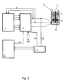
- the signal converter 11 measures two signals: on the one hand, an electrical variable of one phase (voltage or current) and on the other hand, via line 13, the total current of all phases. This is based on the fact that the addition of the three sinusoidal currents, which must be present at the common base point, does not give a constant. Rather, a ripple remains in which the frequency of the three sinusoidal signals and thus also the rotational frequency of the rotor is present.
- the signal converter 11 outputs the signal to the second control unit 9, which shuts off the drive output stage 6 in the event of a speed deviation, for example exceeding the maximum speed or a significant deviation of the actual speed from the setpoint speed.
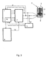
- the exemplary embodiment shown in FIG. 3 has a signal converter 15 as a special feature. This may be a separate component, but it is more advantageous to arrange it in the first control unit 1. By this transducer, it is particularly easy to make a potential separation between the drive train, which is composed of first control unit, drive output stage and motor, and the second control unit. This is desirable because the powertrain is operated at high potential due to power injection.
- the transformed signal is then supplied via at least one line 16 of the second control unit.
- control units can be designed both as programmable microcontrollers and as control ICs. In the latter, the engine model and the other functions is statically installed. A data exchange can take place between the control units in which data is exchanged via the motor itself, via speed limits and actual / setpoint values. Depending on the utilization of the computing capacity, the second control unit can take on additional tasks that have to do with the periphery of the vacuum pump 3, for example the control of a fieldbus or a temperature management system.
Landscapes
- Engineering & Computer Science (AREA)
- Mechanical Engineering (AREA)
- General Engineering & Computer Science (AREA)
- Non-Positive Displacement Air Blowers (AREA)
- Control Of Motors That Do Not Use Commutators (AREA)
- Control Of Ac Motors In General (AREA)
Abstract
Description
- Die Erfindung betrifft eine Vorrichtung zur redundanten Drehzahlüberwachung eines sinusförmig, sensorlos kommutierten Synchronmotors mit permanentmagnetisch erregtem Rotor, welche eine erste Steuereinheit, eine Antriebsendstufe und eine Mehrzahl von Antriebsphasen aufweist.
- In einer Vielzahl von Anwendungen haben sich sensorlose und sinusförmig kommutierte Synchronmotore mit permanentmagnetisch erregtem Rotor durchgesetzt. Einer der Vorteile gegenüber anderen Systemen, wie beispielsweise blockkommutierte Antriebe, liegt in dem sehr gleichmäßigen Verlauf des durch das drehende Feld erzeugten Drehmomentes. Daher erzeugt diese Art Antriebe wesentlich weniger Vibrationen, was in vielen Anwendungen erwünscht oder gar Vorraussetzung ist.
- Oftmals werden diese Antriebe in Maschinen eingesetzt, welche Sicherheitsbestimmungen genügen müssen. Dazu gehört zum einen, dass die Drehzahl überwacht werden muss und einen maximalen Wert nicht überschreiten darf. Zum anderen muss diese Überwachung sicher gegen Fehlfunktion der Überwachungseinheit sein. Im Stand der Technik ist es üblich, eine Überwachung der Drehzahl über einen eigens installierten Drehzahlsensor durchzuführen. Dies ist dadurch bedingt, dass im Gegensatz zur Blockkommutierung bei der sinusförmigen Bestromung zu jedem Zeitpunkt alle Phasen bestromt sind. Während es bei Blockkommutierung möglich ist, den Drehzahlsensor (beispielsweise ein Hallsensor oder ein Hall-IC) dadurch zu vermeiden, dass die in der jeweils unbestromten Spule induzierte Spannung gemessen wird, entfällt dieser Lösungsweg bei sinusförmiger Bestromung.
- Der Nachteil dieser Sensoren ist, dass sie erstens ein zusätzliches Bauteil im Bereich des Antriebes darstellen. Das bedeutet unter anderem, dass Kabel und Steckverbindungen vorgesehen werden müssen, um den Sensor auswerten zu können. Das zweite Problem ist, dass solche Sensoren störanfällig sind, weshalb eine Mehrzahl von ihnen vorgesehen werden muss, um eine wirklich zuverlässige Überwachung realisieren zu können. Zudem sind die Sensorbauteile empfindlich gegen chemische Einwirkungen und störanfällig gegen elektromagnetische oder radioaktive Einflüsse.
- Die Aufgabe ist es daher, eine Vorrichtung zur redundanten Drehzahlüberwachung eines sinusförmig, sensorlos kommutierten Synchronmotors vorzustellen, die die vorgenannten Nachteile vermeidet.
- Gelöst wird diese Aufgabe durch eine Vorrichtung mit den Merkmalen des ersten Patentanspruches.
- Dadurch, dass eine zweite Steuereinheit eine elektrische Größe mindestens einer Antriebsphase überwacht, kann auf einen Drehzahlsensor jeglicher Art verzichtet werden. Dies beseitigt ein störanfälliges Bauteil, wodurch die Sicherheit entscheidend erhöht und überdies noch Kosten eingespart werden können.
- Die Merkmale der Ansprüche 2 bis 5 stellen vorteilhafte Weiterbildungen der Erfindung dar.
- In einer ersten Weiterbildung ist die überwachte elektrische Größe die durch die Antriebsendstufe an den Motor angelegte Spannung in mindestens einer Phase. Die Messung dieser elektrischen Größe ist besonders einfach, was den nötigen Aufwand gering hält.
- In einer anderen Weiterbildung ist die überwachte elektrische Größe der sich in der betreffenden Antriebsphase einstellende Strom. Dies ist zwar aufwändiger als die vorgenannte Lösung, hat aber als Vorteil, dass sich Ströme aufgrund der Wechselwirkung der Endstufe mit dem Motor selbst einstellen und somit durch die Strommessung auch der Einfluss des Motors berücksichtigt wird.
- Eine weitere Ausführungsform bezieht sich auf den Signalweg von der Messung der elektrischen Größe zur zweiten Steuereinheit. Vorteilhaft ist es, das Messsignal von einem Signalumformer umformen zu lassen, der in der ersten Steuereinheit angeordnet ist und von welchem das Signal dann an die zweite Steuereinheit geführt wird. Die Umformung geschieht so mit derselben Zeitbasis wie die Rechnung des Motormodells, womit Fehler durch unterschiedlichen Zeitbasen vermieden und ein Abgleich von Zeitbasen unnötig wird.
- Die Sensorlosigkeit wirkt sich besonders günstig beim Einsatz der Vorrichtung in einer Vakuumpumpe mit schnelldrehendem Rotor aus. Solche Vakuumpumpen sind beispielsweise Turbomolekularpumpen, die oftmals in schwierigen chemischen und physikalischen Umfeldern eingesetzt werden. Aus diesen und aus Kostengründen ist es wichtig, die Zahl der elektronischen Bauteile innerhalb der Vakuumpumpe zu minimieren. Außerdem muss bei diesen Vakuumpumpen eine sichere Drehzahlüberwachung gewährleistet sein, da in dem schnell drehenden Rotor eine enorme kinetische Energie gespeichert ist. Sollte diese im Falle einer Fehlfunktion frei werden, muss das Gehäuse der Vakuumpumpe diese Energie absorbieren. Da die Energie von der Drehzahl abhängt, muss die Drehzahl effizient und sicher auf einen Maximalwert begrenzt werden, um das Gehäuse noch sicher genug bauen zu können.
- Anhand von Ausführungsbeispielen soll die Erfindung erläutert und die Vorteile vertieft werden.
- Fig. 1:
- Prinzipschaltbild eines ersten Ausführungsbeispiels
- Fig. 2:
- Prinzipschaltbild eines zweiten Ausführungsbeispiels
- Fig. 3:
- Prinzipschaltbild eines dritten Ausführungsbeispiels
- Alle Ausführungsformen weisen folgende Komponenten auf, die mit Verweis auf die erste Abbildung erläutert werden, bei den anderen Abbildungen aber genauso gelten. Eine erste Steuereinheit 1 stellt die eigentliche Antriebssteuereinheit dar. In ihr läuft ein sogenanntes Motormodell ab, welches aufgrund der physikalischen Parameter des Motors die Kommutierung berechnet. Weiterhin führt diese Steuereinheit eine Stromregelung durch, in dem sie die Ströme von zwei Motorphasen über eine Mehrzahl von Leitungen 8 auswertet. Die Messung des Stromes ist hier nur zur Vereinfachung als Punktmessung und ohne weitere Schaltungsdetails dargestellt. Die erste Steuereinheit sorgt für das Anschleppen des Motors von Nulldrehzahl auf nominelle Drehzahl. In ihr läuft eine erste Drehzahlüberwachung, die bei Erkennen einer zu hohen Motordrehzahl den Antrieb stoppt. Der Einsatz eines Motormodells fußt auf der Erkenntnis, dass sich der permanentmagnetisch erregte Rotor eines Synchronmotor nur mit der Drehzahl drehen kann, mit der das erregende Feld dreht, welches die Motorspulen erzeugen. Die erste Steuereinheit gibt die Kommutierungssignale an die Antriebsendstufe 2. In ihr wird die durch die Netzspannungsversorgung gegebene Leistung entsprechend der vom Motormodell errechneten Kommuntierungssignale auf die einzelnen Motorphasen aufgeschaltet. Schematisch dargestellt ist eine Vakuumpumpe 3 mit einem schnelldrehenden Rotor 4, einem Pumpstator 7, die beide Schaufeln tragen, welche im Zusammenspiel eine Pumpwirkung erzeugen. Der Rotor ist in Lagern 6 gelagert und der Antrieb 5 als permanentmagnetisch erregter Synchronmotor (PMSM) ausgebildet. Als weitere Bestandteile weist die Vorrichtung eine zweite Steuereinheit 9 auf, welche die Rotordrehzahl überwacht und bei Vorliegen einer nicht mehr tolerierbaren Abweichung über eine Leitung 10 den Antriebsendstufe abschaltet. Die Drehzahlüberwachung fußt auf den von einem Signalumsetzer zugeführten Informationen.
- In einer ersten Ausführungsform misst der Signalumsetzer zwei der an die Motorphasen angelegten Spannungen über die Leitungen 12.
- In einer zweiten Ausführungsform misst der Signalumsetzer über die Leitungen 12 zwei der sich in den Motorphasen einstellenden Ströme.
- Ein weiteres Ausführungsbeispiel zeigt Abbildung 2. Der Signalumsetzer 11 misst zwei Signale: Zum einen eine elektrische Größe einer Phase (Spannung oder Strom) und zum anderen über Leitung 13 den Summenstrom aller Phasen. Dies fußt darauf, dass die Addition der drei Sinusströme, die am gemeinsamen Fußpunkt vorliegen muss, keine Konstante ergibt. Vielmehr bleibt eine Welligkeit, in der die Frequenz der drei Sinussignale und damit auch die Drehfrequenz des Rotors vorhanden ist. Wieder gibt der Signalumsetzer 11 das Signal an die zweite Steuereinheit 9, die im Falle einer Drehzahlabweichung, beispielsweise eine Überschreitung der maximalen Drehzahl oder eine erhebliche Abweichung der Ist- von der Solldrehzahl, die Antriebsendstufe 6 abschaltet.
- Das in Abbildung 3 gezeigte Ausführungsbeispiel weist als Besonderheit einen Signalumformer 15 auf. Dieser kann ein eigenes Bauteil sein, vorteilhafter ist es jedoch, ihn in der ersten Steuereinheit 1 anzuordnen. Durch diesen Signalumformer ist es besonders leicht möglich, eine Potenzialtrennung zwischen dem Antriebsstrang, welcher aus erster Steuereinheit, Antriebsendstufe und Motor aufgebaut ist, und der zweiten Steuereinheit vorzunehmen. Dies ist wünschenswert, weil der Antriebsstrang aufgrund der Leistungseinkopplung auf hohem Potenzial betrieben wird. Das umgeformte Signal wird dann über mindestens eine Leitung 16 der zweiten Steuereinheit zugeführt.
- Weiterbildungen der Erfindung sind denkbar. So können die Steuereinheiten sowohl als programmierbare Mikrokontroller als auch als Steuer-IC's ausgebildet sein. In letzteren ist das Motormodell und die weiteren Funktionen statisch eingebaut. Zwischen den Steuereinheiten kann ein Datenaustausch stattfinden, in dem Daten über den Motor selbst, über Drehzahlgrenzen und Ist-/Sollwerte ausgetauscht werden. Je nach Auslastung der Rechenkapazität kann die zweite Steuereinheit Zusatzaufgaben übernehmen, die mit der Peripherie der Vakuumpumpe 3 zu tun haben, beispielsweise die Kontrolle eines Feldbusses oder eines Temperaturmanagementsystems.
Claims (5)
- Vorrichtung zur redundanten Drehzahlüberwachung eines sinusförmig, sensorlos kommutierten Synchronmotors mit permanentmagnetisch erregtem Rotor, welche eine erste Steuereinheit (1), eine Antriebsendstufe (2) und eine Mehrzahl von Antriebsphasen aufweist, dadurch gekennzeichnet, dass eine zweite Steuereinheit (9) ein elektrische Größe mindestens einer der Antriebsphasen überwacht und eine Verbindung (10) zwischen zweiter Steuereinheit und Antriebsendstufe besteht, über welche die zweite Steuereinheit die Antriebsendstufe bei Erkennen eines fehlerhaften Drehzahlzustandes abschaltet.
- Vorrichtung nach Anspruch 1, dadurch gekennzeichnet, dass die überwachte elektrische Größe die an die betreffende Antriebsphase angelegte Spannung ist.
- Vorrichtung nach Anspruch 1, dadurch gekennzeichnet, dass die überwachte elektrische Größe der sich in der betreffenden Antriebsphase einstellende Strom ist.
- Vorrichtung nach einem der vorhergehenden Ansprüche, dadurch gekennzeichnet, dass das der elektrische Größe entsprechenden Messsignal einem in der ersten Steuereinheit (1) angeordneten Signalumformer (15) zugeführt wird und das umgeformte Signal der zweiten Steuereinheit (9) über eine Verbindung (16) zugeführt wird.
- Vorrichtung nach einem der vorhergehenden Ansprüche, dadurch gekennzeichnet, dass die Vorrichtung als Antrieb einer Vakuumpumpe (3) mit schnelldrehendem Rotor (4) dient.
Applications Claiming Priority (1)
| Application Number | Priority Date | Filing Date | Title |
|---|---|---|---|
| DE102005045284A DE102005045284A1 (de) | 2005-09-22 | 2005-09-22 | Drehzahlüberwachungsvorrichtung |
Publications (3)
| Publication Number | Publication Date |
|---|---|
| EP1768222A2 true EP1768222A2 (de) | 2007-03-28 |
| EP1768222A3 EP1768222A3 (de) | 2008-07-16 |
| EP1768222B1 EP1768222B1 (de) | 2019-03-20 |
Family
ID=37517193
Family Applications (1)
| Application Number | Title | Priority Date | Filing Date |
|---|---|---|---|
| EP06019124.4A Active EP1768222B1 (de) | 2005-09-22 | 2006-09-13 | Drehzahlüberwachungsvorrichtung |
Country Status (4)
| Country | Link |
|---|---|
| US (1) | US7378815B2 (de) |
| EP (1) | EP1768222B1 (de) |
| JP (1) | JP2007089386A (de) |
| DE (1) | DE102005045284A1 (de) |
Cited By (1)
| Publication number | Priority date | Publication date | Assignee | Title |
|---|---|---|---|---|
| DE102005051565B4 (de) | 2004-10-29 | 2019-03-21 | Valeo Equipements Electriques Moteur | Verfahren und Anlage zur Überwachung einer Abschaltphase eines Verbrennungsmotors |
Families Citing this family (5)
| Publication number | Priority date | Publication date | Assignee | Title |
|---|---|---|---|---|
| DE102009035998A1 (de) | 2009-07-27 | 2011-02-03 | Pilz Gmbh & Co. Kg | Verfahren und Vorrichtung zum fehlersicheren Überwachen einer Bewegungsgröße an einem elektrischen Antrieb |
| DE102009055991A1 (de) | 2009-11-23 | 2011-05-26 | Pilz Gmbh & Co. Kg | Sicherheitsschaltungsanordnung und Verfahren zum fehlsicheren Überwachen einer Bewegungsgröße |
| WO2011061345A1 (de) | 2009-11-23 | 2011-05-26 | Pilz Gmbh & Co. Kg | Sicherheitsschaltungsanordnung und verfahren zum fehlersicheren überwachen einer bewegungsgrösse |
| US8796980B2 (en) * | 2012-10-19 | 2014-08-05 | General Electric Company | Fault detection system and method for overspeed protection speed sensors |
| EP3001271B1 (de) | 2014-09-24 | 2020-03-18 | Siemens Aktiengesellschaft | Verfahren und Vorrichtung zur Überwachung einer Bewegungsgröße eines Antriebs |
Citations (1)
| Publication number | Priority date | Publication date | Assignee | Title |
|---|---|---|---|---|
| EP1211774A1 (de) | 2000-11-29 | 2002-06-05 | Siemens Aktiengesellschaft | Sichere Geschwindigkeitsüberwachung für geberlose Drehstromantriebe |
Family Cites Families (18)
| Publication number | Priority date | Publication date | Assignee | Title |
|---|---|---|---|---|
| JPS5361034A (en) * | 1976-11-12 | 1978-06-01 | Hitachi Ltd | Air conditioner protective system |
| JPS6035911B2 (ja) * | 1978-02-01 | 1985-08-17 | ソニー株式会社 | 回転体の回転制御装置 |
| SE8501435L (sv) | 1985-03-22 | 1986-09-23 | Anders Lennart Ohlin | Cykel, ny utformning av ramen |
| DE3531198A1 (de) * | 1985-08-31 | 1987-03-12 | Bosch Gmbh Robert | Sicherheits- und notfahrverfahren fuer eine brennkraftmaschine mit selbstzuendung und einrichtung zu dessen durchfuehrung |
| US4712372A (en) * | 1985-09-18 | 1987-12-15 | Avco Corporation | Overspeed system redundancy monitor |
| US4667114A (en) * | 1986-04-16 | 1987-05-19 | General Electric Company | Prime mover speed sensing system and method |
| DE4237971B4 (de) * | 1992-11-11 | 2004-05-06 | Unaxis Deutschland Holding Gmbh | Vakuumpumpe mit Wandler |
| DE69613810T2 (de) * | 1996-04-04 | 2001-10-25 | Stmicroelectronics S.R.L., Agrate Brianza | Synchronsteuerung der Phasenwicklungen eines Gleichstrommotors mit vorbestimmten digitalisierten permanent gespeicherten Ansteuerungsprofilen, deren Auslesung mit der Rotorstellung synchronisiert ist zur Optimierung des Drehmomentsverlaufs |
| FR2753319B1 (fr) * | 1996-09-10 | 1998-12-04 | Soc D Mecanique Magnetique | Dispositif de detection de la position angulaire pour le pilotage d'un moteur synchrone a excitation par aimant permanent |
| JP3419725B2 (ja) * | 1999-01-27 | 2003-06-23 | 松下電器産業株式会社 | 位置センサレスモータ制御装置 |
| JP4154635B2 (ja) * | 1999-05-31 | 2008-09-24 | 株式会社デンソー | センサレス・ブラシレスdcモータ制御装置 |
| JP4249916B2 (ja) * | 2000-09-18 | 2009-04-08 | エドワーズ株式会社 | ブラシレスモータの制御回路、ブラシレスモータ装置、及び真空ポンプ装置 |
| US6549871B1 (en) * | 2001-05-03 | 2003-04-15 | Delphi Technologies, Inc. | Current estimation for an electric machine |
| DE10154690A1 (de) * | 2001-11-09 | 2003-05-28 | Lenze Drive Systems Gmbh | Verfahren zur sicherheitsgerichteten Drehzahlüberwachung eines geregelten Antriebsmotors |
| DE10215896A1 (de) * | 2002-04-11 | 2003-10-23 | Leybold Vakuum Gmbh | Vakuumpumpe |
| US7184927B2 (en) * | 2004-03-26 | 2007-02-27 | Honeywell International Inc. | Adaptive position sensing method and apparatus for synchronous motor generator system |
| US6940251B1 (en) * | 2004-04-30 | 2005-09-06 | Honeywell International Inc. | Decoupling of cross coupling for floating reference frame controllers for sensorless control of synchronous machines |
| US7002318B1 (en) * | 2004-09-23 | 2006-02-21 | General Motors Corporation | Position sensor fault tolerant control for automotive propulsion system |
-
2005
- 2005-09-22 DE DE102005045284A patent/DE102005045284A1/de not_active Withdrawn
-
2006
- 2006-08-21 JP JP2006224094A patent/JP2007089386A/ja active Pending
- 2006-09-13 EP EP06019124.4A patent/EP1768222B1/de active Active
- 2006-09-15 US US11/522,247 patent/US7378815B2/en not_active Expired - Fee Related
Patent Citations (1)
| Publication number | Priority date | Publication date | Assignee | Title |
|---|---|---|---|---|
| EP1211774A1 (de) | 2000-11-29 | 2002-06-05 | Siemens Aktiengesellschaft | Sichere Geschwindigkeitsüberwachung für geberlose Drehstromantriebe |
Cited By (1)
| Publication number | Priority date | Publication date | Assignee | Title |
|---|---|---|---|---|
| DE102005051565B4 (de) | 2004-10-29 | 2019-03-21 | Valeo Equipements Electriques Moteur | Verfahren und Anlage zur Überwachung einer Abschaltphase eines Verbrennungsmotors |
Also Published As
| Publication number | Publication date |
|---|---|
| DE102005045284A1 (de) | 2007-03-29 |
| EP1768222A3 (de) | 2008-07-16 |
| US20070066433A1 (en) | 2007-03-22 |
| US7378815B2 (en) | 2008-05-27 |
| JP2007089386A (ja) | 2007-04-05 |
| EP1768222B1 (de) | 2019-03-20 |
Similar Documents
| Publication | Publication Date | Title |
|---|---|---|
| DE102005045283B4 (de) | Vakuumpumpsystem | |
| DE69524032T2 (de) | Regelungsverfahren zum antrieb eines bürstenlosen gleichstrommotors, vorrichtung dafür und elektrische maschine, die diese vorrichtung verwendet | |
| DE60124832T2 (de) | Bürstenloser Motor | |
| EP1768222B1 (de) | Drehzahlüberwachungsvorrichtung | |
| DE112013005190T5 (de) | Verbesserungen bei elektrischen Servolenksystemen | |
| DE112017003161T5 (de) | Stromrichtervorrichtung | |
| DE102012014319A1 (de) | Steuervorrichtung, die erfasst, ob eine irreversible Entmagnetisierung in einem Permanentmagneten eines Permanentmagnetsynchronmotors auftrat oder nicht | |
| EP3109999B1 (de) | Verfahren und vorrichtung zur ermittlung einer physikalischen grösse einer mehrphasen-synchronmaschine | |
| DE102007040217A1 (de) | Sensorloser Betrieb einer elektronisch kommutierten Gleichstrommaschine | |
| EP2544364B1 (de) | Momentenbeobachter auf der Basis der Messung von Ausgangsströmen und Ausgangsspannungen | |
| DE10041606B4 (de) | Elektromotorischer Antrieb und Verfahren zum Betreiben eines elektronisch kommutierten Elektromotors | |
| WO2015067530A1 (de) | Redundante rotorlageermittlung | |
| DE102010053098A1 (de) | Verfahren zur Überwachung eines Rotorlagegebers | |
| EP2215713A2 (de) | Stillstandsrotorpositionserkennungsverfahren | |
| WO2020064536A1 (de) | Verfahren zur ermittlung eines eine winkeldifferenz zwischen einer angenommenen und einer tatsächlichen lage einer d-achse beschreibenden korrekturwerts, steuerungseinrichtung und wechselrichter | |
| DE102004019284A1 (de) | Vorrichtung zum Betrieb eines Synchronmotors | |
| DE102012012762B4 (de) | Einrichtung zur Bestimmung von Positionen eines Rotors in elektrischen Maschinen | |
| EP3014756B1 (de) | Verfahren zur erkennung einer winkelfehlstellung eines elektrischen motors | |
| EP2998753B1 (de) | Überwachungsvorrichtung für eine elektromaschine, steuervorrichtung und verfahren | |
| DE19751375A1 (de) | Verfahren zur Rekonstruktion von Lastkräften bzw. Lastmomenten sowie Beschleunigungen bei elektrischen Antrieben aus den Informationen der Klemmengrößen im geschlossenen Drehzahl- oder Lageregelkreis | |
| EP2596579A2 (de) | Verfahren und vorrichtung zur sensorlosen lageerkennung einer elektronisch kommutierten elektrischen maschine | |
| DE202006012200U1 (de) | Antriebssystem | |
| WO2020099412A1 (de) | Elektromotorbaugruppe mit fehlerfallerkennung und verfahren zum betrieb einer elektromotorbaugruppe | |
| EP1796258B1 (de) | Elektromotor und Verfahren zum Anregen eines solchen | |
| DE102019215282B3 (de) | Verfahren zum Betreiben einer elektrischen Maschine |
Legal Events
| Date | Code | Title | Description |
|---|---|---|---|
| PUAI | Public reference made under article 153(3) epc to a published international application that has entered the european phase |
Free format text: ORIGINAL CODE: 0009012 |
|
| AK | Designated contracting states |
Kind code of ref document: A2 Designated state(s): AT BE BG CH CY CZ DE DK EE ES FI FR GB GR HU IE IS IT LI LT LU LV MC NL PL PT RO SE SI SK TR |
|
| AX | Request for extension of the european patent |
Extension state: AL BA HR MK YU |
|
| PUAL | Search report despatched |
Free format text: ORIGINAL CODE: 0009013 |
|
| AK | Designated contracting states |
Kind code of ref document: A3 Designated state(s): AT BE BG CH CY CZ DE DK EE ES FI FR GB GR HU IE IS IT LI LT LU LV MC NL PL PT RO SE SI SK TR |
|
| AX | Request for extension of the european patent |
Extension state: AL BA HR MK RS |
|
| 17P | Request for examination filed |
Effective date: 20081120 |
|
| 17Q | First examination report despatched |
Effective date: 20090216 |
|
| AKX | Designation fees paid |
Designated state(s): AT BE BG CH CY CZ DE DK EE ES FI FR GB GR HU IE IS IT LI LT LU LV MC NL PL PT RO SE SI SK TR |
|
| REG | Reference to a national code |
Ref country code: DE Ref legal event code: R079 Ref document number: 502006016204 Country of ref document: DE Free format text: PREVIOUS MAIN CLASS: H02H0007093000 Ipc: H02H0007080000 |
|
| GRAP | Despatch of communication of intention to grant a patent |
Free format text: ORIGINAL CODE: EPIDOSNIGR1 |
|
| STAA | Information on the status of an ep patent application or granted ep patent |
Free format text: STATUS: GRANT OF PATENT IS INTENDED |
|
| RIC1 | Information provided on ipc code assigned before grant |
Ipc: F04D 27/02 20060101ALI20180831BHEP Ipc: H02H 7/08 20060101AFI20180831BHEP Ipc: H02H 7/093 20060101ALI20180831BHEP |
|
| INTG | Intention to grant announced |
Effective date: 20181002 |
|
| GRAS | Grant fee paid |
Free format text: ORIGINAL CODE: EPIDOSNIGR3 |
|
| GRAA | (expected) grant |
Free format text: ORIGINAL CODE: 0009210 |
|
| STAA | Information on the status of an ep patent application or granted ep patent |
Free format text: STATUS: THE PATENT HAS BEEN GRANTED |
|
| REG | Reference to a national code |
Ref country code: DE Ref legal event code: R081 Ref document number: 502006016204 Country of ref document: DE Owner name: PFEIFFER VACUUM GMBH, DE Free format text: FORMER OWNER: PFEIFFER VACUUM GMBH, 35614 ASSLAR, DE |
|
| AK | Designated contracting states |
Kind code of ref document: B1 Designated state(s): AT BE BG CH CY CZ DE DK EE ES FI FR GB GR HU IE IS IT LI LT LU LV MC NL PL PT RO SE SI SK TR |
|
| REG | Reference to a national code |
Ref country code: GB Ref legal event code: FG4D Free format text: NOT ENGLISH |
|
| REG | Reference to a national code |
Ref country code: CH Ref legal event code: EP |
|
| REG | Reference to a national code |
Ref country code: DE Ref legal event code: R096 Ref document number: 502006016204 Country of ref document: DE |
|
| REG | Reference to a national code |
Ref country code: AT Ref legal event code: REF Ref document number: 1111489 Country of ref document: AT Kind code of ref document: T Effective date: 20190415 |
|
| REG | Reference to a national code |
Ref country code: IE Ref legal event code: FG4D Free format text: LANGUAGE OF EP DOCUMENT: GERMAN |
|
| REG | Reference to a national code |
Ref country code: NL Ref legal event code: MP Effective date: 20190320 |
|
| PG25 | Lapsed in a contracting state [announced via postgrant information from national office to epo] |
Ref country code: FI Free format text: LAPSE BECAUSE OF FAILURE TO SUBMIT A TRANSLATION OF THE DESCRIPTION OR TO PAY THE FEE WITHIN THE PRESCRIBED TIME-LIMIT Effective date: 20190320 Ref country code: SE Free format text: LAPSE BECAUSE OF FAILURE TO SUBMIT A TRANSLATION OF THE DESCRIPTION OR TO PAY THE FEE WITHIN THE PRESCRIBED TIME-LIMIT Effective date: 20190320 Ref country code: LT Free format text: LAPSE BECAUSE OF FAILURE TO SUBMIT A TRANSLATION OF THE DESCRIPTION OR TO PAY THE FEE WITHIN THE PRESCRIBED TIME-LIMIT Effective date: 20190320 |
|
| REG | Reference to a national code |
Ref country code: LT Ref legal event code: MG4D |
|
| PG25 | Lapsed in a contracting state [announced via postgrant information from national office to epo] |
Ref country code: NL Free format text: LAPSE BECAUSE OF FAILURE TO SUBMIT A TRANSLATION OF THE DESCRIPTION OR TO PAY THE FEE WITHIN THE PRESCRIBED TIME-LIMIT Effective date: 20190320 Ref country code: LV Free format text: LAPSE BECAUSE OF FAILURE TO SUBMIT A TRANSLATION OF THE DESCRIPTION OR TO PAY THE FEE WITHIN THE PRESCRIBED TIME-LIMIT Effective date: 20190320 Ref country code: GR Free format text: LAPSE BECAUSE OF FAILURE TO SUBMIT A TRANSLATION OF THE DESCRIPTION OR TO PAY THE FEE WITHIN THE PRESCRIBED TIME-LIMIT Effective date: 20190621 Ref country code: BG Free format text: LAPSE BECAUSE OF FAILURE TO SUBMIT A TRANSLATION OF THE DESCRIPTION OR TO PAY THE FEE WITHIN THE PRESCRIBED TIME-LIMIT Effective date: 20190620 |
|
| PG25 | Lapsed in a contracting state [announced via postgrant information from national office to epo] |
Ref country code: EE Free format text: LAPSE BECAUSE OF FAILURE TO SUBMIT A TRANSLATION OF THE DESCRIPTION OR TO PAY THE FEE WITHIN THE PRESCRIBED TIME-LIMIT Effective date: 20190320 Ref country code: RO Free format text: LAPSE BECAUSE OF FAILURE TO SUBMIT A TRANSLATION OF THE DESCRIPTION OR TO PAY THE FEE WITHIN THE PRESCRIBED TIME-LIMIT Effective date: 20190320 Ref country code: ES Free format text: LAPSE BECAUSE OF FAILURE TO SUBMIT A TRANSLATION OF THE DESCRIPTION OR TO PAY THE FEE WITHIN THE PRESCRIBED TIME-LIMIT Effective date: 20190320 Ref country code: SK Free format text: LAPSE BECAUSE OF FAILURE TO SUBMIT A TRANSLATION OF THE DESCRIPTION OR TO PAY THE FEE WITHIN THE PRESCRIBED TIME-LIMIT Effective date: 20190320 Ref country code: PT Free format text: LAPSE BECAUSE OF FAILURE TO SUBMIT A TRANSLATION OF THE DESCRIPTION OR TO PAY THE FEE WITHIN THE PRESCRIBED TIME-LIMIT Effective date: 20190720 |
|
| PG25 | Lapsed in a contracting state [announced via postgrant information from national office to epo] |
Ref country code: PL Free format text: LAPSE BECAUSE OF FAILURE TO SUBMIT A TRANSLATION OF THE DESCRIPTION OR TO PAY THE FEE WITHIN THE PRESCRIBED TIME-LIMIT Effective date: 20190320 |
|
| PG25 | Lapsed in a contracting state [announced via postgrant information from national office to epo] |
Ref country code: IS Free format text: LAPSE BECAUSE OF FAILURE TO SUBMIT A TRANSLATION OF THE DESCRIPTION OR TO PAY THE FEE WITHIN THE PRESCRIBED TIME-LIMIT Effective date: 20190720 |
|
| REG | Reference to a national code |
Ref country code: DE Ref legal event code: R097 Ref document number: 502006016204 Country of ref document: DE |
|
| PLBE | No opposition filed within time limit |
Free format text: ORIGINAL CODE: 0009261 |
|
| STAA | Information on the status of an ep patent application or granted ep patent |
Free format text: STATUS: NO OPPOSITION FILED WITHIN TIME LIMIT |
|
| PG25 | Lapsed in a contracting state [announced via postgrant information from national office to epo] |
Ref country code: DK Free format text: LAPSE BECAUSE OF FAILURE TO SUBMIT A TRANSLATION OF THE DESCRIPTION OR TO PAY THE FEE WITHIN THE PRESCRIBED TIME-LIMIT Effective date: 20190320 |
|
| 26N | No opposition filed |
Effective date: 20200102 |
|
| PG25 | Lapsed in a contracting state [announced via postgrant information from national office to epo] |
Ref country code: SI Free format text: LAPSE BECAUSE OF FAILURE TO SUBMIT A TRANSLATION OF THE DESCRIPTION OR TO PAY THE FEE WITHIN THE PRESCRIBED TIME-LIMIT Effective date: 20190320 |
|
| PG25 | Lapsed in a contracting state [announced via postgrant information from national office to epo] |
Ref country code: TR Free format text: LAPSE BECAUSE OF FAILURE TO SUBMIT A TRANSLATION OF THE DESCRIPTION OR TO PAY THE FEE WITHIN THE PRESCRIBED TIME-LIMIT Effective date: 20190320 |
|
| PG25 | Lapsed in a contracting state [announced via postgrant information from national office to epo] |
Ref country code: MC Free format text: LAPSE BECAUSE OF FAILURE TO SUBMIT A TRANSLATION OF THE DESCRIPTION OR TO PAY THE FEE WITHIN THE PRESCRIBED TIME-LIMIT Effective date: 20190320 |
|
| REG | Reference to a national code |
Ref country code: CH Ref legal event code: PL |
|
| PG25 | Lapsed in a contracting state [announced via postgrant information from national office to epo] |
Ref country code: IE Free format text: LAPSE BECAUSE OF NON-PAYMENT OF DUE FEES Effective date: 20190913 Ref country code: CH Free format text: LAPSE BECAUSE OF NON-PAYMENT OF DUE FEES Effective date: 20190930 Ref country code: LI Free format text: LAPSE BECAUSE OF NON-PAYMENT OF DUE FEES Effective date: 20190930 Ref country code: LU Free format text: LAPSE BECAUSE OF NON-PAYMENT OF DUE FEES Effective date: 20190913 |
|
| REG | Reference to a national code |
Ref country code: BE Ref legal event code: MM Effective date: 20190930 |
|
| PG25 | Lapsed in a contracting state [announced via postgrant information from national office to epo] |
Ref country code: BE Free format text: LAPSE BECAUSE OF NON-PAYMENT OF DUE FEES Effective date: 20190930 |
|
| REG | Reference to a national code |
Ref country code: AT Ref legal event code: MM01 Ref document number: 1111489 Country of ref document: AT Kind code of ref document: T Effective date: 20190913 |
|
| PG25 | Lapsed in a contracting state [announced via postgrant information from national office to epo] |
Ref country code: AT Free format text: LAPSE BECAUSE OF NON-PAYMENT OF DUE FEES Effective date: 20190913 |
|
| PG25 | Lapsed in a contracting state [announced via postgrant information from national office to epo] |
Ref country code: CY Free format text: LAPSE BECAUSE OF FAILURE TO SUBMIT A TRANSLATION OF THE DESCRIPTION OR TO PAY THE FEE WITHIN THE PRESCRIBED TIME-LIMIT Effective date: 20190320 |
|
| PG25 | Lapsed in a contracting state [announced via postgrant information from national office to epo] |
Ref country code: HU Free format text: LAPSE BECAUSE OF FAILURE TO SUBMIT A TRANSLATION OF THE DESCRIPTION OR TO PAY THE FEE WITHIN THE PRESCRIBED TIME-LIMIT; INVALID AB INITIO Effective date: 20060913 |
|
| PGFP | Annual fee paid to national office [announced via postgrant information from national office to epo] |
Ref country code: GB Payment date: 20230920 Year of fee payment: 18 Ref country code: CZ Payment date: 20230905 Year of fee payment: 18 |
|
| PGFP | Annual fee paid to national office [announced via postgrant information from national office to epo] |
Ref country code: FR Payment date: 20230928 Year of fee payment: 18 |
|
| PGFP | Annual fee paid to national office [announced via postgrant information from national office to epo] |
Ref country code: IT Payment date: 20230927 Year of fee payment: 18 Ref country code: DE Payment date: 20231128 Year of fee payment: 18 |