EP1767698A2 - Couvercle latéral réglable en hauteur pour une lisseuse d'un finisseur - Google Patents
Couvercle latéral réglable en hauteur pour une lisseuse d'un finisseur Download PDFInfo
- Publication number
- EP1767698A2 EP1767698A2 EP06019908A EP06019908A EP1767698A2 EP 1767698 A2 EP1767698 A2 EP 1767698A2 EP 06019908 A EP06019908 A EP 06019908A EP 06019908 A EP06019908 A EP 06019908A EP 1767698 A2 EP1767698 A2 EP 1767698A2
- Authority
- EP
- European Patent Office
- Prior art keywords
- screed
- height
- side plate
- lifting devices
- stripping
- Prior art date
- Legal status (The legal status is an assumption and is not a legal conclusion. Google has not performed a legal analysis and makes no representation as to the accuracy of the status listed.)
- Withdrawn
Links
Images

Classifications
-
- E—FIXED CONSTRUCTIONS
- E01—CONSTRUCTION OF ROADS, RAILWAYS, OR BRIDGES
- E01C—CONSTRUCTION OF, OR SURFACES FOR, ROADS, SPORTS GROUNDS, OR THE LIKE; MACHINES OR AUXILIARY TOOLS FOR CONSTRUCTION OR REPAIR
- E01C19/00—Machines, tools or auxiliary devices for preparing or distributing paving materials, for working the placed materials, or for forming, consolidating, or finishing the paving
- E01C19/48—Machines, tools or auxiliary devices for preparing or distributing paving materials, for working the placed materials, or for forming, consolidating, or finishing the paving for laying-down the materials and consolidating them, or finishing the surface, e.g. slip forms therefor, forming kerbs or gutters in a continuous operation in situ
-
- E—FIXED CONSTRUCTIONS
- E01—CONSTRUCTION OF ROADS, RAILWAYS, OR BRIDGES
- E01C—CONSTRUCTION OF, OR SURFACES FOR, ROADS, SPORTS GROUNDS, OR THE LIKE; MACHINES OR AUXILIARY TOOLS FOR CONSTRUCTION OR REPAIR
- E01C19/00—Machines, tools or auxiliary devices for preparing or distributing paving materials, for working the placed materials, or for forming, consolidating, or finishing the paving
- E01C19/22—Machines, tools or auxiliary devices for preparing or distributing paving materials, for working the placed materials, or for forming, consolidating, or finishing the paving for consolidating or finishing laid-down unset materials
- E01C19/30—Tamping or vibrating apparatus other than rollers ; Devices for ramming individual paving elements
- E01C19/34—Power-driven rammers or tampers, e.g. air-hammer impacted shoes for ramming stone-sett paving; Hand-actuated ramming or tamping machines, e.g. tampers with manually hoisted dropping weight
- E01C19/40—Power-driven rammers or tampers, e.g. air-hammer impacted shoes for ramming stone-sett paving; Hand-actuated ramming or tamping machines, e.g. tampers with manually hoisted dropping weight adapted to impart a smooth finish to the paving, e.g. tamping or vibrating finishers
-
- E—FIXED CONSTRUCTIONS
- E01—CONSTRUCTION OF ROADS, RAILWAYS, OR BRIDGES
- E01C—CONSTRUCTION OF, OR SURFACES FOR, ROADS, SPORTS GROUNDS, OR THE LIKE; MACHINES OR AUXILIARY TOOLS FOR CONSTRUCTION OR REPAIR
- E01C19/00—Machines, tools or auxiliary devices for preparing or distributing paving materials, for working the placed materials, or for forming, consolidating, or finishing the paving
- E01C19/22—Machines, tools or auxiliary devices for preparing or distributing paving materials, for working the placed materials, or for forming, consolidating, or finishing the paving for consolidating or finishing laid-down unset materials
- E01C19/42—Machines for imparting a smooth finish to freshly-laid paving courses other than by rolling, tamping or vibrating
Definitions
- the present invention relates to a device for adjusting a height of a side plate of a paver relative to a screed of the paver, the side shield by at least two separately height-adjustable lifting devices, which are attached to a main frame of the paver, which is connectable to the screed attached, lifted and can be lowered in order to prevent a built-in material from escaping sideways, before the building material is compacted by the screed to a road surface.
- the present invention relates to a method for manufacturing a pavement with a paver, the a screed with a maximum paving width and which is provided with a device according to the invention, wherein the road surface to be produced has a width which is greater than the maximum installation width.
- Paver is understood below to mean a class of construction machines, such as e.g. Pavers with which so-called paving material of various qualities (such as asphalt, concrete or the like) can be laid on a subsoil intended for this purpose, such as, for example, asphalt.
- a planum as far as possible in high compression quality just and profile-appropriate laid. Planum refers to a base course on which a road, a path, a building or similar can be built.
- Telescope collars are known with which varying road widths can be made.
- a screed then consists of several elements, of which at least one transverse to the installation direction, ie parallel to the width of the road, can be moved variably. In this way, different road widths can be made.
- this technique also reaches its limit, namely, when the telescopic screed is maximally extended.
- This object is achieved with a device for adjusting a height of a side plate of a paver according to the type mentioned above, wherein the two lifting devices are connected to one another with a connecting element and a central adjusting device is provided which cooperates with the connecting element such that the two separately height-adjustable Lifting devices are simultaneously height adjustable by actuation of the adjustment.
- the side plate of a paver can be easily lifted and lowered in a simple manner.
- the actuation of the two lifting devices is effected by a central movement of the adjusting mechanism according to the present invention.
- Manual operation of the lifting devices as is common in the art, has only a secondary meaning. The sometimes very time and effort consuming Verstellarbeit deleted completely.
- the two lifting devices can be quickly raised and lowered together, so that a road widening beyond the permissible installation width can be done easily and quickly.
- Another advantage of the present invention is that the device according to the invention can be easily and quickly mounted on existing side plates or their lifting devices, so that a conversion of a side plate according to the prior art towards a side plate according to the present invention easily, quickly and cost is possible.
- the central adjusting device is driven mechanically, electrically or hydraulically.
- the lifting devices are realized as headstocks, which are each connected via a chain to the side plate, and when the connecting element is a traverse, which is connected to the central adjusting device.
- the two separately height-adjustable lifting devices are arranged symmetrically to the side plate, and the central adjusting device is arranged centrally between the two lifting devices and connected to the main frame.
- This arrangement geometry prevents the force exerted on the two lifting devices by the adjusting device according to the invention being distributed unevenly. Due to the symmetrical arrangement experienced both lifting devices an equally large force component, so that tilting of the side plate can be excluded.
- the central adjusting device comprises an adapter plate, a drive unit and an adjustment mechanism, wherein the adapter plate and the adjustment mechanism are coordinated such that the adjustment gradually can cause a change in height by the adjustment on the adapter plate and climbs up, the adjustment mechanism in the Snap adapter plate when a desired height is reached.
- the engagement of the adjustment mechanism in the adapter plate ensures that the desired height adjustment does not change during a work process.
- An adjustment mechanism, which can climb up or down on the adapter plate, can be produced in a simple manner. This results in a cost-effective production, so that, for example, a retrofitting of existing road paver can be done cheaply.
- Another advantage is the fact that in addition a fold-off stripping device is provided, which is mounted laterally of the screed with a hinge on the main frame to, when the side plate is in a raised state, the built-in, then laterally next to the screed is led to strip.
- the operation is further simplified by the worker does not have to distribute the laterally conveyed next to the screed built-in to reduce it to a desired covering thickness. Similar to the screed, the scraper simply travels over the additional screed in addition to the screed and pulls this additional slick "smooth". This measure in turn increases the speed with which an additional road width can be made.
- the stripping device comprises a detent element with which the stripping device can be fixed relative to the main frame at a desired angle relative to an installation direction.
- the stripping device is height adjustable relative to the main frame.
- a covering thickness can be made laterally next to the screed of the paver, which differs from the lining thickness, which is made by the screed.
- a thicker side coating could be made by the distance between scraper and planum is chosen to be greater than the distance between screed and Planum.
- a height dimension can be set, which end-compressed state of the covering can be achieved profile accurate.
- the stripping device comprises an extension plate, with which a stripping length is variably adjustable.
- an extension plate can be used to increase the maximum installation width required.
- the stripping device comprises a heating element.
- the heating element ensures that the built-in material, which is usually poured hot in front of the screed, does not stick to the scraper and affects the surface of the covering.
- the inventive method comprises the following steps: adjusting the side plate in the raised state by operating the central adjusting device; Unfolding and locking the stripping device; Conveying the material to be installed via a distributing device upstream of the screed, in particular a screw, beyond the width of the screed; and stripping of beyond the screed also funded built-in.
- Fig. 1 shows a schematic side view of a road paver 10, which has a height-adjustable side plate according to the present invention.
- the road paver 10 is movable in a driving and installation direction 14 using caterpillars 12, which can also be replaced by wheels.
- a main frame 18 is attached to which in turn a screed 20 is attached. With the help of screed 20 to be produced road surface 22 is compacted and smoothed.
- the screed 20 is connected to a lateral support frame 24, which may be formed in one or more pieces with the main frame 18.
- the main frame 18, and thus also the elements 20 and 24 connected to it, can be height-adjusted or swiveled in the direction of an arrow 26.
- the main frame 18 may be connected, for example, with a lifting cylinder 27.
- the built-in material not shown in Fig. 1 is conveyed by means of a screw 28 transversely to the installation direction 14, that is perpendicular to the plane of the drawing of FIG. 1, before the screed 20 for subsequent compression.
- the built-in material is usually in a front portion 30 of the paver 10, for example, using a dump truck (not shown), tilted.
- the built-in material is then transported through the interior of the road paver 10 in the direction of the screw 28, which in turn distributes the built-in transverse to the direction of travel 14.
- Side shield 32 is provided.
- the side shield 32 is height-adjustable, as indicated by an arrow 34.
- the side plate 32 in a raised Condition (see also Fig. 4).
- the side shield 32 is normally lowered almost to the level of the subgrade, so that no paving material is conveyed beyond the width of the screed 20.
- FIG. 2 shows a schematic plan view of a lower part of a road paver 10.
- a screed 20 is shown, which extends beyond the width of the paver 10 on the left.
- a stripping device 42 is shown schematically in FIG.
- the stripping device 42 comprises a stripping plate 44, which in turn is connected to a hinge 46.
- the hinge 46 is attached to the side support frame 24.
- the stripping device 42 may have a hand lever 48 to rotate the stripping device in the direction of the double arrow 49.
- the stripping device is designed to be height adjustable.
- the Rastierstange 50 serves to fix the stripping device 42 relative to the lateral support frame 24th
- the angle between the direction of travel 14 and the stripper plate 40 is substantially 90 °. This represents the usual working position of the stripping 42, to strip sideways next to the screed 20 supplied insert.
- the side plate 32 is sufficiently raised so that the distribution screw 28
- the latching rod 50 is rotatably mounted on the stripping device 42 and has at its end facing the paver 10 a hook which can be hung in correspondingly prepared holes in the side support frame 24 (not shown).
- the angle between the stripper plate and the direction of travel 14 the effective length of the stripper and thus the additional width of the pavement 22 to be manufactured can be varied.
- the hand lever 48 is provided only optional. Just as well, the stripping device 42 could be operated automatically. Further, the stripper plate 44 could be designed to be adjustable in axial length by the stripper plate 44 is either telescopic or other plate elements (not shown), which can be opened when needed.
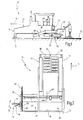
- a side shield 32 is shown in the lowered condition.
- a central adjusting device 60 is provided.
- the central adjusting device 60 comprises a mechanism for lifting and lowering the side plate 32.
- the mechanism 62 can climb on an adapter plate 64, which has a Rastierance 66, or climb.
- the adjustment mechanism of the invention could be similar to a jack.
- the Rastiermann 66 of FIG. 3 has a toothing 68, with which the mechanism 62 can interact.
- the Rastiermann 66 'of FIG. 4 alternatively has holes 70.
- so-called headstocks 72 and 74 are shown on the left and right of the central adjusting device 60. With the help of the headstocks 72 and 74, the relative height of the side shield 32 can be adjusted.
- the headstocks 72 and 74 each include a hand lever 76 for manually adjusting the height by turning. At their opposite end they have chains 78 which are fixedly connected to the side plate 32. Inside the headstocks a threaded shaft 80 is provided, with the help of the height adjustment can be performed.
- these two headstocks are now connected rigidly to one another by means of a connecting element or a cross member 82.
- Traverse 82 is configured to include two bearing units (not shown) for receiving the headstocks 72 and 74.
- the headstocks are threaded side each connected to corresponding threaded holes in a guide pin. These guide pins can be adjusted via the spindle operation.
- the guide pins are guided in vertically extending pipe guides, resulting in a downwardly formed U-shaped guide unit.
- Guide pins connected to the headstocks have at their lower end a receptacle for the chain links 78.
- the chain links 78 provide the vertical connection to the side shield 32 and are dimensioned so that they can also be absorbed by the pipe guides. Due to this arrangement, it is possible, the side plate 32 by means of the lifting devices 72 and 74, and thus also by means of the central adjusting device 60, gradually and quickly to move parallel up or down. Nevertheless, the possibility of manual actuation of the headstocks is maintained.
- Fig. 3 The downward movement is indicated in Fig. 3 by an arrow 84.
- Fig. 4 the upward movement is illustrated by an arrow 86.
- FIG. 3 Also shown in FIG. 3 is the nest 88 which is transported by the auger 28 shown in FIGS. 1 and 2 toward the side end of the screed 20.
- the auger 28 is not shown in FIG.
- Fig. 4 the side plate is shown in a raised position.
- the height difference .DELTA.H can be clearly seen and is well above the height difference that is usually achieved with lifting devices that do not interact with the central adjustment device 60 according to the invention.
- the height difference ⁇ H makes it possible to transport the building material laterally next to the screed. If there is a stripping direction 42 (see Fig. 2), this laterally transported paving material can be smoothed quickly and easily.
Applications Claiming Priority (1)
| Application Number | Priority Date | Filing Date | Title |
|---|---|---|---|
| DE200510047096 DE102005047096B3 (de) | 2005-09-26 | 2005-09-26 | Höhenverstellbares Seitenschild für Einbaubohle eines Straßenfertigers |
Publications (2)
| Publication Number | Publication Date |
|---|---|
| EP1767698A2 true EP1767698A2 (fr) | 2007-03-28 |
| EP1767698A3 EP1767698A3 (fr) | 2007-10-24 |
Family
ID=37607332
Family Applications (1)
| Application Number | Title | Priority Date | Filing Date |
|---|---|---|---|
| EP06019908A Withdrawn EP1767698A3 (fr) | 2005-09-26 | 2006-09-22 | Couvercle latéral réglable en hauteur pour une lisseuse d'un finisseur |
Country Status (2)
| Country | Link |
|---|---|
| EP (1) | EP1767698A3 (fr) |
| DE (1) | DE102005047096B3 (fr) |
Cited By (4)
| Publication number | Priority date | Publication date | Assignee | Title |
|---|---|---|---|---|
| CN106638234A (zh) * | 2016-11-08 | 2017-05-10 | 长安大学 | 一种改进后的同步封层车 |
| CN108560389A (zh) * | 2018-06-05 | 2018-09-21 | 江苏集萃道路工程技术与装备研究所有限公司 | 一种加热墙作业执行机构及其沥青路面加热机 |
| US11274404B2 (en) | 2019-03-13 | 2022-03-15 | Caterpillar Paving Products Inc. | Retention apparatus for screed cover |
| CN114382265A (zh) * | 2020-10-19 | 2022-04-22 | 广东博智林机器人有限公司 | 一种摊铺布料装置及铺料设备 |
Families Citing this family (1)
| Publication number | Priority date | Publication date | Assignee | Title |
|---|---|---|---|---|
| DE102011018469B4 (de) * | 2011-04-21 | 2019-11-07 | Bomag Gmbh | Fertiger und Vorrichtung zum Verstellen eines Seitenschildes |
Citations (3)
| Publication number | Priority date | Publication date | Assignee | Title |
|---|---|---|---|---|
| US5344254A (en) * | 1993-04-14 | 1994-09-06 | Blaw-Knox Construction Equipment Corporation | Pivoting screed edger |
| DE29708888U1 (de) * | 1997-05-20 | 1997-07-17 | Voegele Ag J | Einbaubohle für einen Straßenfertiger |
| EP1033441A2 (fr) * | 1999-03-02 | 2000-09-06 | BITELLI S.p.A. | Finisseuse de route vibrante pour asphalte |
Family Cites Families (1)
| Publication number | Priority date | Publication date | Assignee | Title |
|---|---|---|---|---|
| DE9313162U1 (de) * | 1993-09-01 | 1993-10-28 | Voegele Ag J | Einbaubohle |
-
2005
- 2005-09-26 DE DE200510047096 patent/DE102005047096B3/de not_active Expired - Fee Related
-
2006
- 2006-09-22 EP EP06019908A patent/EP1767698A3/fr not_active Withdrawn
Patent Citations (3)
| Publication number | Priority date | Publication date | Assignee | Title |
|---|---|---|---|---|
| US5344254A (en) * | 1993-04-14 | 1994-09-06 | Blaw-Knox Construction Equipment Corporation | Pivoting screed edger |
| DE29708888U1 (de) * | 1997-05-20 | 1997-07-17 | Voegele Ag J | Einbaubohle für einen Straßenfertiger |
| EP1033441A2 (fr) * | 1999-03-02 | 2000-09-06 | BITELLI S.p.A. | Finisseuse de route vibrante pour asphalte |
Cited By (5)
| Publication number | Priority date | Publication date | Assignee | Title |
|---|---|---|---|---|
| CN106638234A (zh) * | 2016-11-08 | 2017-05-10 | 长安大学 | 一种改进后的同步封层车 |
| CN108560389A (zh) * | 2018-06-05 | 2018-09-21 | 江苏集萃道路工程技术与装备研究所有限公司 | 一种加热墙作业执行机构及其沥青路面加热机 |
| CN108560389B (zh) * | 2018-06-05 | 2024-04-16 | 江苏集萃道路工程技术与装备研究所有限公司 | 一种加热墙作业执行机构及其沥青路面加热机 |
| US11274404B2 (en) | 2019-03-13 | 2022-03-15 | Caterpillar Paving Products Inc. | Retention apparatus for screed cover |
| CN114382265A (zh) * | 2020-10-19 | 2022-04-22 | 广东博智林机器人有限公司 | 一种摊铺布料装置及铺料设备 |
Also Published As
| Publication number | Publication date |
|---|---|
| DE102005047096B3 (de) | 2007-02-15 |
| EP1767698A3 (fr) | 2007-10-24 |
Similar Documents
| Publication | Publication Date | Title |
|---|---|---|
| EP2199467B1 (fr) | Poutre égaliseuse et procédé destiné à la fabrication d'un revêtement de chaussée | |
| EP1213389B1 (fr) | Machine à coffrage glissant | |
| EP2169117B1 (fr) | Finisseur | |
| DE102013007061B4 (de) | Höhenverstellvorrichtung für eine Ausfahrbohle eines Straßenfertigers sowie Straßenfertiger mit einer derartigen Höhenverstellvorrichtung | |
| EP2845952A1 (fr) | Machine à coffrage glissant, et procédé d'adaptation de la largeur d'une poutre dameuse | |
| WO2018033516A1 (fr) | Finisseur de talus | |
| DE19709131C2 (de) | Deckenfertiger | |
| EP2428614B1 (fr) | Finisseuse mobile | |
| EP3498913B1 (fr) | Finisseuse de route pourvue d'un châssis pouvant être relevé | |
| EP2886718A1 (fr) | Poutre dameuse pour une finisseuse de route | |
| DE102005047096B3 (de) | Höhenverstellbares Seitenschild für Einbaubohle eines Straßenfertigers | |
| EP3498916A1 (fr) | Finisseur de route pourvu de déflecteur de matériau pivotant | |
| EP3498915B1 (fr) | Finisseuse de route pourvue de châssis pouvant être relevé | |
| EP3926096B1 (fr) | Dispositif de compactage du sol destiné au compactage d'une couche de revêtement de terrain naturel, rouleau d'asphalte et procédé de fonctionnement d'un dispositif de compactage du sol | |
| DE19652396C1 (de) | Deckenfertiger | |
| EP3575491B1 (fr) | Finisseuse de route avec plaque de limitation d'extension | |
| WO2001066860A1 (fr) | Dispositif supplementaire pour un finisseur | |
| EP3135815A1 (fr) | Table de lissage pour un finisseur | |
| EP1180560B1 (fr) | Poutre lisseuse pour un finisseur | |
| DE102020120833B4 (de) | Anbauvorrichtung für einen Lastkraftwagen zum Aufbringen einer Deckschicht aus schüttfähigem Baumaterial auf einem Straßen- und/oder Wegeunterbau | |
| DE60020180T2 (de) | Vibrierende Strassendeckenfertiger für Asphalt | |
| EP4144916B1 (fr) | Agencement de poutre lisseuse pour une finisseuse de route | |
| EP1644584A1 (fr) | Procede de production de couches de pierres concassees | |
| DE202004004748U1 (de) | Straßendeckenfertiger | |
| EP2982803B1 (fr) | Engin avec appareil niveleur associé et procédé de nivellement avec cet engin |
Legal Events
| Date | Code | Title | Description |
|---|---|---|---|
| PUAI | Public reference made under article 153(3) epc to a published international application that has entered the european phase |
Free format text: ORIGINAL CODE: 0009012 |
|
| AK | Designated contracting states |
Kind code of ref document: A2 Designated state(s): AT BE BG CH CY CZ DE DK EE ES FI FR GB GR HU IE IS IT LI LT LU LV MC NL PL PT RO SE SI SK TR |
|
| AX | Request for extension of the european patent |
Extension state: AL BA HR MK YU |
|
| PUAL | Search report despatched |
Free format text: ORIGINAL CODE: 0009013 |
|
| AK | Designated contracting states |
Kind code of ref document: A3 Designated state(s): AT BE BG CH CY CZ DE DK EE ES FI FR GB GR HU IE IS IT LI LT LU LV MC NL PL PT RO SE SI SK TR |
|
| AX | Request for extension of the european patent |
Extension state: AL BA HR MK YU |
|
| AKX | Designation fees paid | ||
| STAA | Information on the status of an ep patent application or granted ep patent |
Free format text: STATUS: THE APPLICATION IS DEEMED TO BE WITHDRAWN |
|
| 18D | Application deemed to be withdrawn |
Effective date: 20080425 |
|
| REG | Reference to a national code |
Ref country code: DE Ref legal event code: 8566 |