EP1767698A2 - Height-adjustable side cover for a screed of a road paver - Google Patents
Height-adjustable side cover for a screed of a road paver Download PDFInfo
- Publication number
- EP1767698A2 EP1767698A2 EP06019908A EP06019908A EP1767698A2 EP 1767698 A2 EP1767698 A2 EP 1767698A2 EP 06019908 A EP06019908 A EP 06019908A EP 06019908 A EP06019908 A EP 06019908A EP 1767698 A2 EP1767698 A2 EP 1767698A2
- Authority
- EP
- European Patent Office
- Prior art keywords
- screed
- height
- side plate
- lifting devices
- stripping
- Prior art date
- Legal status (The legal status is an assumption and is not a legal conclusion. Google has not performed a legal analysis and makes no representation as to the accuracy of the status listed.)
- Withdrawn
Links
Images

Classifications
-
- E—FIXED CONSTRUCTIONS
- E01—CONSTRUCTION OF ROADS, RAILWAYS, OR BRIDGES
- E01C—CONSTRUCTION OF, OR SURFACES FOR, ROADS, SPORTS GROUNDS, OR THE LIKE; MACHINES OR AUXILIARY TOOLS FOR CONSTRUCTION OR REPAIR
- E01C19/00—Machines, tools or auxiliary devices for preparing or distributing paving materials, for working the placed materials, or for forming, consolidating, or finishing the paving
- E01C19/48—Machines, tools or auxiliary devices for preparing or distributing paving materials, for working the placed materials, or for forming, consolidating, or finishing the paving for laying-down the materials and consolidating them, or finishing the surface, e.g. slip forms therefor, forming kerbs or gutters in a continuous operation in situ
-
- E—FIXED CONSTRUCTIONS
- E01—CONSTRUCTION OF ROADS, RAILWAYS, OR BRIDGES
- E01C—CONSTRUCTION OF, OR SURFACES FOR, ROADS, SPORTS GROUNDS, OR THE LIKE; MACHINES OR AUXILIARY TOOLS FOR CONSTRUCTION OR REPAIR
- E01C19/00—Machines, tools or auxiliary devices for preparing or distributing paving materials, for working the placed materials, or for forming, consolidating, or finishing the paving
- E01C19/22—Machines, tools or auxiliary devices for preparing or distributing paving materials, for working the placed materials, or for forming, consolidating, or finishing the paving for consolidating or finishing laid-down unset materials
- E01C19/30—Tamping or vibrating apparatus other than rollers ; Devices for ramming individual paving elements
- E01C19/34—Power-driven rammers or tampers, e.g. air-hammer impacted shoes for ramming stone-sett paving; Hand-actuated ramming or tamping machines, e.g. tampers with manually hoisted dropping weight
- E01C19/40—Power-driven rammers or tampers, e.g. air-hammer impacted shoes for ramming stone-sett paving; Hand-actuated ramming or tamping machines, e.g. tampers with manually hoisted dropping weight adapted to impart a smooth finish to the paving, e.g. tamping or vibrating finishers
-
- E—FIXED CONSTRUCTIONS
- E01—CONSTRUCTION OF ROADS, RAILWAYS, OR BRIDGES
- E01C—CONSTRUCTION OF, OR SURFACES FOR, ROADS, SPORTS GROUNDS, OR THE LIKE; MACHINES OR AUXILIARY TOOLS FOR CONSTRUCTION OR REPAIR
- E01C19/00—Machines, tools or auxiliary devices for preparing or distributing paving materials, for working the placed materials, or for forming, consolidating, or finishing the paving
- E01C19/22—Machines, tools or auxiliary devices for preparing or distributing paving materials, for working the placed materials, or for forming, consolidating, or finishing the paving for consolidating or finishing laid-down unset materials
- E01C19/42—Machines for imparting a smooth finish to freshly-laid paving courses other than by rolling, tamping or vibrating
Definitions
- the present invention relates to a device for adjusting a height of a side plate of a paver relative to a screed of the paver, the side shield by at least two separately height-adjustable lifting devices, which are attached to a main frame of the paver, which is connectable to the screed attached, lifted and can be lowered in order to prevent a built-in material from escaping sideways, before the building material is compacted by the screed to a road surface.
- the present invention relates to a method for manufacturing a pavement with a paver, the a screed with a maximum paving width and which is provided with a device according to the invention, wherein the road surface to be produced has a width which is greater than the maximum installation width.
- Paver is understood below to mean a class of construction machines, such as e.g. Pavers with which so-called paving material of various qualities (such as asphalt, concrete or the like) can be laid on a subsoil intended for this purpose, such as, for example, asphalt.
- a planum as far as possible in high compression quality just and profile-appropriate laid. Planum refers to a base course on which a road, a path, a building or similar can be built.
- Telescope collars are known with which varying road widths can be made.
- a screed then consists of several elements, of which at least one transverse to the installation direction, ie parallel to the width of the road, can be moved variably. In this way, different road widths can be made.
- this technique also reaches its limit, namely, when the telescopic screed is maximally extended.
- This object is achieved with a device for adjusting a height of a side plate of a paver according to the type mentioned above, wherein the two lifting devices are connected to one another with a connecting element and a central adjusting device is provided which cooperates with the connecting element such that the two separately height-adjustable Lifting devices are simultaneously height adjustable by actuation of the adjustment.
- the side plate of a paver can be easily lifted and lowered in a simple manner.
- the actuation of the two lifting devices is effected by a central movement of the adjusting mechanism according to the present invention.
- Manual operation of the lifting devices as is common in the art, has only a secondary meaning. The sometimes very time and effort consuming Verstellarbeit deleted completely.
- the two lifting devices can be quickly raised and lowered together, so that a road widening beyond the permissible installation width can be done easily and quickly.
- Another advantage of the present invention is that the device according to the invention can be easily and quickly mounted on existing side plates or their lifting devices, so that a conversion of a side plate according to the prior art towards a side plate according to the present invention easily, quickly and cost is possible.
- the central adjusting device is driven mechanically, electrically or hydraulically.
- the lifting devices are realized as headstocks, which are each connected via a chain to the side plate, and when the connecting element is a traverse, which is connected to the central adjusting device.
- the two separately height-adjustable lifting devices are arranged symmetrically to the side plate, and the central adjusting device is arranged centrally between the two lifting devices and connected to the main frame.
- This arrangement geometry prevents the force exerted on the two lifting devices by the adjusting device according to the invention being distributed unevenly. Due to the symmetrical arrangement experienced both lifting devices an equally large force component, so that tilting of the side plate can be excluded.
- the central adjusting device comprises an adapter plate, a drive unit and an adjustment mechanism, wherein the adapter plate and the adjustment mechanism are coordinated such that the adjustment gradually can cause a change in height by the adjustment on the adapter plate and climbs up, the adjustment mechanism in the Snap adapter plate when a desired height is reached.
- the engagement of the adjustment mechanism in the adapter plate ensures that the desired height adjustment does not change during a work process.
- An adjustment mechanism, which can climb up or down on the adapter plate, can be produced in a simple manner. This results in a cost-effective production, so that, for example, a retrofitting of existing road paver can be done cheaply.
- Another advantage is the fact that in addition a fold-off stripping device is provided, which is mounted laterally of the screed with a hinge on the main frame to, when the side plate is in a raised state, the built-in, then laterally next to the screed is led to strip.
- the operation is further simplified by the worker does not have to distribute the laterally conveyed next to the screed built-in to reduce it to a desired covering thickness. Similar to the screed, the scraper simply travels over the additional screed in addition to the screed and pulls this additional slick "smooth". This measure in turn increases the speed with which an additional road width can be made.
- the stripping device comprises a detent element with which the stripping device can be fixed relative to the main frame at a desired angle relative to an installation direction.
- the stripping device is height adjustable relative to the main frame.
- a covering thickness can be made laterally next to the screed of the paver, which differs from the lining thickness, which is made by the screed.
- a thicker side coating could be made by the distance between scraper and planum is chosen to be greater than the distance between screed and Planum.
- a height dimension can be set, which end-compressed state of the covering can be achieved profile accurate.
- the stripping device comprises an extension plate, with which a stripping length is variably adjustable.
- an extension plate can be used to increase the maximum installation width required.
- the stripping device comprises a heating element.
- the heating element ensures that the built-in material, which is usually poured hot in front of the screed, does not stick to the scraper and affects the surface of the covering.
- the inventive method comprises the following steps: adjusting the side plate in the raised state by operating the central adjusting device; Unfolding and locking the stripping device; Conveying the material to be installed via a distributing device upstream of the screed, in particular a screw, beyond the width of the screed; and stripping of beyond the screed also funded built-in.
- Fig. 1 shows a schematic side view of a road paver 10, which has a height-adjustable side plate according to the present invention.
- the road paver 10 is movable in a driving and installation direction 14 using caterpillars 12, which can also be replaced by wheels.
- a main frame 18 is attached to which in turn a screed 20 is attached. With the help of screed 20 to be produced road surface 22 is compacted and smoothed.
- the screed 20 is connected to a lateral support frame 24, which may be formed in one or more pieces with the main frame 18.
- the main frame 18, and thus also the elements 20 and 24 connected to it, can be height-adjusted or swiveled in the direction of an arrow 26.
- the main frame 18 may be connected, for example, with a lifting cylinder 27.
- the built-in material not shown in Fig. 1 is conveyed by means of a screw 28 transversely to the installation direction 14, that is perpendicular to the plane of the drawing of FIG. 1, before the screed 20 for subsequent compression.
- the built-in material is usually in a front portion 30 of the paver 10, for example, using a dump truck (not shown), tilted.
- the built-in material is then transported through the interior of the road paver 10 in the direction of the screw 28, which in turn distributes the built-in transverse to the direction of travel 14.
- Side shield 32 is provided.
- the side shield 32 is height-adjustable, as indicated by an arrow 34.
- the side plate 32 in a raised Condition (see also Fig. 4).
- the side shield 32 is normally lowered almost to the level of the subgrade, so that no paving material is conveyed beyond the width of the screed 20.
- FIG. 2 shows a schematic plan view of a lower part of a road paver 10.
- a screed 20 is shown, which extends beyond the width of the paver 10 on the left.
- a stripping device 42 is shown schematically in FIG.
- the stripping device 42 comprises a stripping plate 44, which in turn is connected to a hinge 46.
- the hinge 46 is attached to the side support frame 24.
- the stripping device 42 may have a hand lever 48 to rotate the stripping device in the direction of the double arrow 49.
- the stripping device is designed to be height adjustable.
- the Rastierstange 50 serves to fix the stripping device 42 relative to the lateral support frame 24th
- the angle between the direction of travel 14 and the stripper plate 40 is substantially 90 °. This represents the usual working position of the stripping 42, to strip sideways next to the screed 20 supplied insert.
- the side plate 32 is sufficiently raised so that the distribution screw 28
- the latching rod 50 is rotatably mounted on the stripping device 42 and has at its end facing the paver 10 a hook which can be hung in correspondingly prepared holes in the side support frame 24 (not shown).
- the angle between the stripper plate and the direction of travel 14 the effective length of the stripper and thus the additional width of the pavement 22 to be manufactured can be varied.
- the hand lever 48 is provided only optional. Just as well, the stripping device 42 could be operated automatically. Further, the stripper plate 44 could be designed to be adjustable in axial length by the stripper plate 44 is either telescopic or other plate elements (not shown), which can be opened when needed.
- a side shield 32 is shown in the lowered condition.
- a central adjusting device 60 is provided.
- the central adjusting device 60 comprises a mechanism for lifting and lowering the side plate 32.
- the mechanism 62 can climb on an adapter plate 64, which has a Rastierance 66, or climb.
- the adjustment mechanism of the invention could be similar to a jack.
- the Rastiermann 66 of FIG. 3 has a toothing 68, with which the mechanism 62 can interact.
- the Rastiermann 66 'of FIG. 4 alternatively has holes 70.
- so-called headstocks 72 and 74 are shown on the left and right of the central adjusting device 60. With the help of the headstocks 72 and 74, the relative height of the side shield 32 can be adjusted.
- the headstocks 72 and 74 each include a hand lever 76 for manually adjusting the height by turning. At their opposite end they have chains 78 which are fixedly connected to the side plate 32. Inside the headstocks a threaded shaft 80 is provided, with the help of the height adjustment can be performed.
- these two headstocks are now connected rigidly to one another by means of a connecting element or a cross member 82.
- Traverse 82 is configured to include two bearing units (not shown) for receiving the headstocks 72 and 74.
- the headstocks are threaded side each connected to corresponding threaded holes in a guide pin. These guide pins can be adjusted via the spindle operation.
- the guide pins are guided in vertically extending pipe guides, resulting in a downwardly formed U-shaped guide unit.
- Guide pins connected to the headstocks have at their lower end a receptacle for the chain links 78.
- the chain links 78 provide the vertical connection to the side shield 32 and are dimensioned so that they can also be absorbed by the pipe guides. Due to this arrangement, it is possible, the side plate 32 by means of the lifting devices 72 and 74, and thus also by means of the central adjusting device 60, gradually and quickly to move parallel up or down. Nevertheless, the possibility of manual actuation of the headstocks is maintained.
- Fig. 3 The downward movement is indicated in Fig. 3 by an arrow 84.
- Fig. 4 the upward movement is illustrated by an arrow 86.
- FIG. 3 Also shown in FIG. 3 is the nest 88 which is transported by the auger 28 shown in FIGS. 1 and 2 toward the side end of the screed 20.
- the auger 28 is not shown in FIG.
- Fig. 4 the side plate is shown in a raised position.
- the height difference .DELTA.H can be clearly seen and is well above the height difference that is usually achieved with lifting devices that do not interact with the central adjustment device 60 according to the invention.
- the height difference ⁇ H makes it possible to transport the building material laterally next to the screed. If there is a stripping direction 42 (see Fig. 2), this laterally transported paving material can be smoothed quickly and easily.
Landscapes
- Engineering & Computer Science (AREA)
- Architecture (AREA)
- Civil Engineering (AREA)
- Structural Engineering (AREA)
- Road Paving Machines (AREA)
Abstract
Description
Die vorliegende Erfindung betrifft eine Vorrichtung zum Einstellen einer Höhe eines Seitenschilds eines Straßenfertigers relativ zu einer Einbaubohle des Straßenfertigers, wobei das Seitenschild durch mindestens zwei separat höhenverstellbare Hubeinrichtungen, die an einem Hauptrahmen des Straßenfertigers, der mit der Einbaubohle verbindbar ist, angebracht sind, gehoben und gesenkt werden kann, um ein Einbaugut an einem seitlichen Entweichen zu hindern, bevor das Einbaugut von der Einbaubohle zu einem Straßenbelag verdichtet wird.The present invention relates to a device for adjusting a height of a side plate of a paver relative to a screed of the paver, the side shield by at least two separately height-adjustable lifting devices, which are attached to a main frame of the paver, which is connectable to the screed attached, lifted and can be lowered in order to prevent a built-in material from escaping sideways, before the building material is compacted by the screed to a road surface.
Ferner betrifft die vorliegende Erfindung ein Verfahren zum Fertigen eines Straßenbelags mit einem Straßenfertiger, der eine Einbaubohle mit einer maximalen Einbaubreite aufweist und der mit einer Vorrichtung gemäß der Erfindung versehen ist, wobei der zu fertigende Straßenbelag eine Breite hat, die größer als die maximale Einbaubreite ist.Furthermore, the present invention relates to a method for manufacturing a pavement with a paver, the a screed with a maximum paving width and which is provided with a device according to the invention, wherein the road surface to be produced has a width which is greater than the maximum installation width.
Aus dem Stand der Technik sind bei Straßenfertigern Seitenschilder bekannt, die mittels zweier separat verstellbarer Hubeinrichtungen in der Höhe verstellbar sind.Side plates are known from the prior art in road pavers, which are adjustable by means of two separately adjustable lifting devices in height.
Unter dem Begriff "Fertiger" wird nachfolgend eine Gattung von Baumaschinen verstanden, wie z.B. Straßenfertiger, mit denen sog. Einbaugut unterschiedlichster Qualität (wie z.B. Asphalt, Beton o.ä.) auf einem hierfür vorgesehenen Untergrund, wie z.B. einem Planum, möglichst in hoher Verdichtungsqualität eben und profilgerecht verlegt wird. Als Planum wird eine Tragschicht bezeichnet, auf der eine Straße, ein Weg, ein Gebäude oder Ähnliches errichtet werden kann.The term "paver" is understood below to mean a class of construction machines, such as e.g. Pavers with which so-called paving material of various qualities (such as asphalt, concrete or the like) can be laid on a subsoil intended for this purpose, such as, for example, asphalt. a planum, as far as possible in high compression quality just and profile-appropriate laid. Planum refers to a base course on which a road, a path, a building or similar can be built.
Unabhängig davon, was mit einem Fertiger errichtet werden soll, können Einsatzort und Einsatzplatz selbst sehr vielfältig sein, wobei Fertiger im Allgemeinen im Straßenbau eingesetzt werden. Andere Anwendungen sind jedoch ebenfalls möglich.Regardless of what is to be built with a paver, the location and place of use itself can be very diverse, with pavers being generally used in road construction. Other applications are also possible.
Gerade im Straßenbau ist es jedoch oft erforderlich, eine variierende Straßenbreite zu fertigen. Insbesondere im Bereich von Straßeneinmündungen, Grundstückseinfahrten oder ähnlichen Ausbuchtungen, die zu einer Verbreiterung der "normalen" Straßenbreite führen, werden herkömmliche Straßenfertiger vor eine Herausforderung gestellt.Especially in road construction, however, it is often necessary to produce a varying road width. In particular, in the area of road junctions, land entrances or similar bulges, which lead to a widening of the "normal" road width, conventional road pavers are challenged.
Im Stand der Technik sind sog. Teleskopeinbaubohlen bekannt, mit denen variierende Straßenbreiten gefertigt werden können. Eine Einbaubohle besteht dann aus mehreren Elementen, von denen zumindest eins quer zur Einbaurichtung, d.h. parallel zur Breite der Straße, variabel verfahren werden kann. Auf diese Weise können unterschiedliche Straßenbreiten gefertigt werden. Jedoch stößt diese Technik auch auf ihre Grenze, nämlich dann, wenn die teleskopierbare Einbaubohle maximal ausgefahren ist.In the prior art, so-called. Telescope collars are known with which varying road widths can be made. A screed then consists of several elements, of which at least one transverse to the installation direction, ie parallel to the width of the road, can be moved variably. In this way, different road widths can be made. However, this technique also reaches its limit, namely, when the telescopic screed is maximally extended.
Bei einer solchen Konstellation ist es im Stand der Technik erforderlich, dass vor die Einbaubohle gefördertes Einbaugut manuell durch einen Arbeiter, beispielsweise unter Zuhilfenahme einer Schaufel, seitlich neben die Einbaubohle geschippt wird, um das außerhalb der erreichbaren Einbaubreite erforderliche Einbaugut bereitstellen zu können. Dieser manuelle Arbeitsvorgang ist für einen Arbeiter zeitaufwendig und körperlich anstrengend. Ferner ergeben sich bei dieser Arbeitsweise auf Grund einer ungleichmäßigen Materialvorlage Qualitätsnachteile.In such a constellation, it is necessary in the prior art that slid in front of the screed promoted property manually by a worker, for example, with the aid of a shovel, laterally next to the screed to provide the required outside the reachable pave width paving. This manual operation is time consuming and physically demanding for a worker. Furthermore, due to an uneven material template quality disadvantages arise in this operation.
Es ist daher eine Aufgabe der vorliegenden Erfindung, eine Vorrichtung und ein Verfahren bereitzustellen, mit denen das Fertigen einer überbreiten Straße auf einfache Weise möglich ist.It is therefore an object of the present invention to provide an apparatus and a method which makes it possible to easily manufacture an over-wide road.
Diese Aufgabe wird mit einer Vorrichtung zum Einstellen einer Höhe eines Seitenschilds eines Straßenfertigers gemäß der eingangs erwähnten Art gelöst, wobei die zwei Hubeinrichtungen mit einem Verbindungselement miteinander verbunden werden und eine zentrale Verstelleinrichtung vorgesehen ist, die mit dem Verbindungselement derart zusammenwirkt, dass die zwei separat höhenverstellbaren Hubeinrichtungen durch eine Betätigung der Verstelleinrichtung gleichzeitig höhenverstellbar sind.This object is achieved with a device for adjusting a height of a side plate of a paver according to the type mentioned above, wherein the two lifting devices are connected to one another with a connecting element and a central adjusting device is provided which cooperates with the connecting element such that the two separately height-adjustable Lifting devices are simultaneously height adjustable by actuation of the adjustment.
Mit der Höhenverstellvorrichtung gemäß der vorliegenden Erfindung kann das Seitenschild eines Straßenfertigers auf einfache Weise zügig gehoben und gesenkt werden. Die Betätigung der beiden Hubvorrichtungen erfolgt durch eine zentrale Bewegung des Verstellmechanismus gemäß der vorliegenden Erfindung. Eine manuelle Betätigung der Hubvorrichtungen, wie es im Stand der Technik üblich ist, hat nur noch eine sekundäre Bedeutung. Die mitunter sehr zeit- und kraftaufwendige Verstellarbeit entfällt vollständig. Die beiden Hubvorrichtungen können gemeinsam schnell gehoben und gesenkt werden, so dass eine Straßenverbreiterung über die zulässige Einbaubreite hinaus einfach und schnell bewerkstelligt werden kann.With the height adjustment device according to the present invention, the side plate of a paver can be easily lifted and lowered in a simple manner. The actuation of the two lifting devices is effected by a central movement of the adjusting mechanism according to the present invention. Manual operation of the lifting devices, as is common in the art, has only a secondary meaning. The sometimes very time and effort consuming Verstellarbeit deleted completely. The two lifting devices can be quickly raised and lowered together, so that a road widening beyond the permissible installation width can be done easily and quickly.
Ein weiterer Vorteil der vorliegenden Erfindung ist, dass die erfindungsgemäße Vorrichtung einfach und schnell an bereits existierende Seitenschilder bzw. deren Hubeinrichtungen montiert werden kann, so dass eine Umrüstung eines Seitenschilds gemäß dem Stand der Technik hin zu einem Seitenschild gemäß der vorliegenden Erfindung einfach, schnell und kostengünstig möglich ist.Another advantage of the present invention is that the device according to the invention can be easily and quickly mounted on existing side plates or their lifting devices, so that a conversion of a side plate according to the prior art towards a side plate according to the present invention easily, quickly and cost is possible.
Gemäß einer bevorzugten Ausführungsform wird die zentrale Verstelleinrichtung mechanisch, elektrisch oder hydraulisch angetrieben.According to a preferred embodiment, the central adjusting device is driven mechanically, electrically or hydraulically.
Durch diese Maßnahme entfällt die Notwendigkeit, die Hubeinrichtungen, wie es im Stand der Technik üblich ist, einzeln manuell zu verstellen.By this measure, eliminates the need to manually adjust the lifting devices, as is customary in the art, individually.
Auch von Vorteil ist, wenn die Hubeinrichtungen als Spindelstöcke realisiert sind, die jeweils über eine Kette mit dem Seitenschild verbunden sind, und wenn das Verbindungselement eine Traverse ist, die mit der zentralen Verstelleinrichtung verbunden ist.It is also advantageous if the lifting devices are realized as headstocks, which are each connected via a chain to the side plate, and when the connecting element is a traverse, which is connected to the central adjusting device.
Spindelstöcke als Hubeinrichtung zu verwenden, ist aus dem Stand der Technik bekannt. Darin liegt ein Vorteil der vorliegenden Erfindung. Die vorliegende Erfindung lässt sich auf Elemente anwenden, die bereits existieren, so dass keine aufwendigen kostspieligen Umrüstarbeiten notwendig sind, um die Erfindung zu realisieren.To use headstocks as a lifting device is known from the prior art. This is an advantage of the present invention. The present invention can be applied to elements that already exist, so that no costly expensive conversion work is necessary to realize the invention.
Gemäß einer weiteren bevorzugten Ausführungsform sind die zwei separat höhenverstellbaren Hubeinrichtungen symmetrisch zum Seitenschild angeordnet, und die zentrale Verstelleinrichtung ist mittig zwischen den beiden Hubeinrichtungen angeordnet und mit dem Hauptrahmen verbunden.According to a further preferred embodiment, the two separately height-adjustable lifting devices are arranged symmetrically to the side plate, and the central adjusting device is arranged centrally between the two lifting devices and connected to the main frame.
Durch diese Anordnungsgeometrie wird verhindert, dass die durch die erfindungsgemäße Einstellvorrichtung auf die zwei Hubeinrichtungen ausgeübte Kraft ungleichmäßig verteilt wird. Durch die symmetrische Anordnung erfahren beide Hubeinrichtungen eine gleich große Kraftkomponente, so dass ein Verkanten des Seitenschilds ausgeschlossen werden kann.This arrangement geometry prevents the force exerted on the two lifting devices by the adjusting device according to the invention being distributed unevenly. Due to the symmetrical arrangement experienced both lifting devices an equally large force component, so that tilting of the side plate can be excluded.
Insbesondere umfasst die zentrale Verstelleinrichtung eine Adapterplatte, eine Antriebseinheit und eine Verstellmechanik, wobei die Adapterplatte und die Verstellmechanik derart aufeinander abgestimmt sind, dass die Verstellmechanik schrittweise eine Höhenänderung bewirken kann, indem die Verstellmechanik an der Adapterplatte auf- und abklettert, wobei die Verstellmechanik in die Adapterplatte einrasten kann, wenn eine gewünschte Höhe erreicht ist.In particular, the central adjusting device comprises an adapter plate, a drive unit and an adjustment mechanism, wherein the adapter plate and the adjustment mechanism are coordinated such that the adjustment gradually can cause a change in height by the adjustment on the adapter plate and climbs up, the adjustment mechanism in the Snap adapter plate when a desired height is reached.
Das Einrasten der Verstellmechanik in die Adapterplatte gewährleistet, dass sich die gewünschte Höheneinstellung während eines Arbeitsvorgangs nicht verändert. Eine Verstellmechanik, die an der Adapterplatte auf- bzw. abklettern kann, lässt sich auf einfache Weise herstellen. Dies resultiert in einer kostengünstigen Herstellung, so dass beispielsweise eine Nachrüstung bereits existierender Straßenfertiger günstig bewerkstelligt werden kann.The engagement of the adjustment mechanism in the adapter plate ensures that the desired height adjustment does not change during a work process. An adjustment mechanism, which can climb up or down on the adapter plate, can be produced in a simple manner. This results in a cost-effective production, so that, for example, a retrofitting of existing road paver can be done cheaply.
Ein weiterer Vorteil ist darin zu sehen, dass zusätzlich eine ausklappbare Abstreifeinrichtung vorgesehen ist, die seitlich der Einbaubohle mit einem Scharnier an dem Hauptrahmen angebracht ist, um, wenn sich das Seitenschild in einem hochgezogenen Zustand befindet, das Einbaugut, das dann seitlich neben die Einbaubohle geführt wird, abzustreifen.Another advantage is the fact that in addition a fold-off stripping device is provided, which is mounted laterally of the screed with a hinge on the main frame to, when the side plate is in a raised state, the built-in, then laterally next to the screed is led to strip.
Durch diese Maßnahme wird der Arbeitsvorgang nochmals vereinfacht, indem der Arbeiter das seitlich neben die Einbaubohle geförderte Einbaugut nicht verteilen muss, um es auf eine gewünschte Belagstärke zu reduzieren. Die Abstreifeinrichtung fährt ähnlich wie die Einbaubohle einfach über das zusätzlich neben die Einbaubohle geförderte Einbaugut hinweg und zieht dieses zusätzliche Einbaugut "glatt". Diese Maßnahme erhöht wiederum die Geschwindigkeit, mit der eine zusätzliche Straßenbreite gefertigt werden kann.By this measure, the operation is further simplified by the worker does not have to distribute the laterally conveyed next to the screed built-in to reduce it to a desired covering thickness. Similar to the screed, the scraper simply travels over the additional screed in addition to the screed and pulls this additional slick "smooth". This measure in turn increases the speed with which an additional road width can be made.
Gemäß einer bevorzugten Ausführungsform umfasst die Abstreifeinrichtung ein Rastierelement, mit dem die Abstreifeinrichtung mit einem gewünschten Winkel relativ zu einer Einbaurichtung gegenüber dem Hauptrahmen festlegbar ist.According to a preferred embodiment, the stripping device comprises a detent element with which the stripping device can be fixed relative to the main frame at a desired angle relative to an installation direction.
Durch das Vorsehen eines Rastierelements ist gewährleistet, dass die Abstreifeinrichtung selbst bei großen Mengen von Einbaugut, welches vor die Abstreifrichtung gefördert wird, nicht zurückgeklappt wird, so dass während des gesamten Einbauvorgangs eine ausgefahrene Abstreifeinrichtung sichergestellt ist.By providing a Rastierelements it is ensured that the stripping device is not folded back even with large amounts of built-in material, which is conveyed before the stripping, so that an extended stripping is ensured during the entire installation process.
Vorzugsweise ist die Abstreifeinrichtung relativ zum Hauptrahmen höhenverstellbar.Preferably, the stripping device is height adjustable relative to the main frame.
Durch diese Maßnahme ist gewährleistet, dass eine Belagstärke seitlich neben der Einbaubohle des Straßenfertigers gefertigt werden kann, die sich von der Belagstärke unterscheidet, die durch die Einbaubohle gefertigt wird. Beispielsweise könnte ein dickerer seitlicher Belag gefertigt werden, indem der Abstand zwischen Abstreifeinrichtung und Planum größer gewählt wird als der Abstand zwischen Einbaubohle und Planum. So lässt sich ein Höhenmaß einstellen, welches endverdichteten Zustand des Belags profilgenau zustande kommen lässt.By this measure it is ensured that a covering thickness can be made laterally next to the screed of the paver, which differs from the lining thickness, which is made by the screed. For example, a thicker side coating could be made by the distance between scraper and planum is chosen to be greater than the distance between screed and Planum. Thus, a height dimension can be set, which end-compressed state of the covering can be achieved profile accurate.
Insbesondere umfasst die Abstreifeinrichtung eine Verlängerungsplatte, mit der eine Abstreiflänge variabel einstellbar ist.In particular, the stripping device comprises an extension plate, with which a stripping length is variably adjustable.
Sollte die durch die Abstreifeinrichtung selbst vorgesehene Abstreiflänge nicht ausreichen, so kann durch eine Verlängerungsplatte auf die maximal erforderliche Einbaubreite vergrößert werden.If the stripping length provided by the stripping device itself is insufficient, an extension plate can be used to increase the maximum installation width required.
Ferner ist es bevorzugt, wenn die Abstreifeinrichtung ein Heizelement umfasst.Furthermore, it is preferred if the stripping device comprises a heating element.
Das Heizelement gewährleistet, dass das Einbaugut, welches in der Regel heiß vor die Einbaubohle geschüttet wird, nicht an der Abstreifeinrichtung festklebt und die Oberfläche des Belags beeinträchtigt.The heating element ensures that the built-in material, which is usually poured hot in front of the screed, does not stick to the scraper and affects the surface of the covering.
Das erfindungsgemäße Verfahren weist die folgenden Schritte auf: Verstellen des Seitenschilds in den hochgezogenen Zustand durch Betätigen der zentralen Verstelleinrichtung; Ausklappen und Einrasten der Abstreifeinrichtung; Fördern des Einbauguts über eine der Einbaubohle vorgelagerte Verteileinrichtung, insbesondere eine Schnecke, über die Breite der Einbaubohle hinaus; und Abstreifen des über die Einbaubohle hinaus geförderten Einbauguts.The inventive method comprises the following steps: adjusting the side plate in the raised state by operating the central adjusting device; Unfolding and locking the stripping device; Conveying the material to be installed via a distributing device upstream of the screed, in particular a screw, beyond the width of the screed; and stripping of beyond the screed also funded built-in.
Auf diese Weise lässt sich eine größere Einbaubreite erreichen, als es durch die übliche Konstruktion der Einbaubohle des Straßenfertigers vorgegeben ist.In this way, a greater paving width can be achieved, as it is predetermined by the usual construction of the screed of the paver.
Es versteht sich, dass die vorstehend genannten und die nachstehend noch zu erläuternden Merkmale nicht nur in der jeweils angegebenen Kombination, sondern auch in anderen Kombinationen oder in Alleinstellung verwendbar sind, ohne den Rahmen der vorliegenden Erfindung zu verlassen.It is understood that the features mentioned above and those yet to be explained below can be used not only in the particular combination given, but also in other combinations or in isolation, without departing from the scope of the present invention.
Ausführungsbeispiele der Erfindung sind in der Zeichnung dargestellt und werden in der nachfolgenden Beschreibung näher erläutert. Es zeigen:
- Fig. 1
- eine schematische Seitenansicht eines Straßenfertigers mit einem höhenverstellbaren Seitenschild gemäß der vorliegenden Erfindung;
- Fig. 2
- eine schematische Draufsicht auf einen unteren Teil eines Straßenfertigers;
- Fig.3
- ein Seitenschild gemäß der vorliegenden Erfindung im abgesenkten Zustand; und
- Fig. 4
- ein Seitenschild gemäß der vorliegenden Erfindung im hochgezogenen Zustand.
- Fig. 1
- a schematic side view of a road finisher with a height-adjustable side plate according to the present invention;
- Fig. 2
- a schematic plan view of a lower part of a paver;
- Figure 3
- a side plate according to the present invention in the lowered state; and
- Fig. 4
- a side plate according to the present invention in the raised state.
In der nachfolgenden Beschreibung werden gleiche Elemente mit gleichen Bezugsziffern bezeichnet werden. Ein Straßenfertiger wird allgemein mit dem. Bezugszeichen 10 bezeichnet werden.In the following description, like elements will be denoted by like reference numerals. A paver becomes common with the.
Fig. 1 zeigt eine schematische Seitenansicht eines Straßenfertigers 10, der ein höhenverstellbares Seitenschild gemäß der vorliegenden Erfindung aufweist.Fig. 1 shows a schematic side view of a
Der Straßenfertiger 10 ist unter Verwendung von Raupen 12, die auch durch Räder ersetzt werden können, in einer Fahr- und Einbaurichtung 14 verfahrbar. Am Körper 16 des Straßenfertigers 10 ist ein Hauptrahmen 18 angebracht, an dem wiederum eine Einbaubohle 20 angebracht ist. Mit Hilfe der Einbaubohle 20 wird ein zu fertigender Straßenbelag 22 verdichtet und glattgezogen.The
Die Einbaubohle 20 ist mit einem seitlichen Trägerrahmen 24 verbunden, der ein- oder mehrstückig mit dem Hauptrahmen 18 ausgebildet sein kann.The
Der Hauptrahmen 18, und somit auch die mit ihm verbundenen Elemente 20 und 24, lassen sich in Richtung eines Pfeils 26 höhenverstellen bzw. verschwenken. Dazu kann der Hauptrahmen 18 beispielsweise mit einem Hubzylinder 27 verbunden sein.The
Das in Fig. 1 nicht dargestellte Einbaugut wird mit Hilfe einer Schnecke 28 quer zur Einbaurichtung 14, d.h. senkrecht zur Zeichnungsebene der Fig. 1, vor der Einbaubohle 20 zur anschließenden Verdichtung befördert. Dazu wird das Einbaugut üblicherweise in einen vorderen Bereich 30 des Straßenfertigers 10, beispielsweise unter Verwendung eines Kippladers (nicht dargestellt), gekippt. Das Einbaugut wird dann durch das Innere des Straßenfertigers 10 in Richtung der Schnecke 28 transportiert, die das Einbaugut wiederum quer zur Fahrtrichtung 14 verteilt. Um das Einbaugut nicht über die Breite der Einbaubohle 20 hinaus zu verteilen, d.h. um einen klar definierten Rand des zu fertigenden Straßenbelags 22 zu gewährleisten, ist ein sog. Seitenschild 32 vorgesehen. Das Seitenschild 32 ist höhenverstellbar, wie es durch einen Pfeil 34 angedeutet ist. In der Fig. 1 ist das Seitenschild 32 in einem hochgezogenen Zustand (vgl. auch Fig. 4) dargestellt. Während eines Fertigungsvorgangs ist das Seitenschild 32 normalerweise fast auf Höhe des Planums abgesenkt, so dass kein Einbaugut über die Breite der Einbaubohle 20 hinaus befördert wird.The built-in material, not shown in Fig. 1 is conveyed by means of a
Fig. 2 zeigt eine schematische Draufsicht auf einen unteren Teil eines Straßenfertigers 10.FIG. 2 shows a schematic plan view of a lower part of a
Man erkennt, dass im vorderen Teil 30 zwei Fördereinrichtungen 36 und 38 vorgesehen sind, mit deren Hilfe angeliefertes Einbaugut in Richtung der Schnecke 28 transportiert wird, von wo es weiter verteilt wird. Dies ist durch einen Pfeil 40 schematisch angedeutet. Die Schnecke 28 verteilt das Einbaugut über die gesamte Breite, d.h. senkrecht zur Fahrtrichtung 14, der Einbaubohle 20.It can be seen that two
In der Fig. 2 ist eine Einbaubohle 20 gezeigt, die links über die Breite des Straßenfertigers 10 hinausragt.2, a
Ferner ist in Fig. 2 eine Abstreifeinrichtung 42 schematisch dargestellt. Die Abstreifeinrichtung 42 umfasst eine Abstreifplatte 44, die wiederum mit einem Scharnier 46 verbunden ist. Das Scharnier 46 ist an dem seitlichen Trägerrahmen 24 angebracht. Ferner kann die Abstreifeinrichtung 42 einen Handhebel 48 aufweisen, um die Abstreifeinrichtung in Richtung des Doppelpfeils 49 zu drehen. Insbesondere ist die Abstreifeinrichtung höhenverstellbar ausgebildet.Furthermore, a stripping
Mit einer gestrichelten Linie ist eine Rastierstange 50 dargestellt. Die Rastierstange 50 dient zur Fixierung der Abstreifeinrichtung 42 relativ zum seitlichen Trägerrahmen 24.With a dashed line a
In der Fig. 2 beträgt der Winkel zwischen der Fahrtrichtung 14 und der Abstreifplatte 40 im Wesentlichen 90°. Dies stellt die übliche Arbeitsstellung der Abstreifrichtung 42 dar, um seitlich neben die Einbaubohle 20 geliefertes Einbaugut abzustreifen. Dazu wird das Seitenschild 32 ausreichend angehoben, so dass die Verteilschnecke 28In Fig. 2, the angle between the direction of
Einbaugut über die Breite der Einbaubohle 20 hinaus vor die Abstreifeinrichtung 42 fördert.Incorporated beyond the width of the
Natürlich können auch andere Winkel zwischen der Abstreifplatte 42 und der Fahrtrichtung 14 eingestellt werden. Vorzugsweise ist die Einraststange 50 drehbar an der Abstreifeinrichtung 42 angebracht und weist an ihrem dem Straßenfertiger 10 zugewandten Ende einen Haken auf, der in entsprechend vorbereitete Löcher im seitlichen Trägerrahmen 24 (nicht dargestellt) eingehängt werden kann. Durch die Variation des Winkels zwischen der Abstreifplatte und der Fahrtrichtung 14 kann die effektive Länge der Abstreifeinrichtung und somit die zusätzliche Breite des zu fertigenden Straßenbelags 22 variiert werden.Of course, other angles between the
Es versteht sich, dass der Handhebel 48 lediglich optional vorgesehen ist. Genauso gut könnte die Abstreifeinrichtung 42 automatisiert betrieben werden. Ferner könnte die Abstreifplatte 44 hinsichtlich ihrer axialen Länge verstellbar ausgestaltet sein, indem die Abstreifplatte 44 entweder teleskopierbar ist oder weitere Plattenelemente (nicht dargestellt) aufweist, die bei Bedarf aufgeklappt werden können.It is understood that the
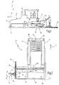
Bezug nehmend auf Fig. 3 ist nun ein Seitenschild 32 im abgesenkten Zustand dargestellt.Referring now to Fig. 3, a
Zum Verstellen der relativen Höhe des Seitenschilds 32 ist eine zentrale Verstelleinrichtung 60 vorgesehen. Die zentrale Verstelleinrichtung 60 umfasst eine Mechanik zum Heben und Senken des Seitenschilds 32. Die Mechanik 62 kann an einer Adapterplatte 64, die eine Rastierleiste 66 aufweist, auf- bzw. abklettern. Der Verstellmechanismus der Erfindung könnte beispielsweise ähnlich wie ein Wagenheber ausgebildet sein. Die Rastierleiste 66 der Fig. 3 weist eine Verzahnung 68 auf, mit der die Mechanik 62 wechselwirken kann. Die Rastierleiste 66' der Fig. 4 weist alternativ Löcher 70 auf.To adjust the relative height of the
Zurückkehrend zu Fig. 3 sind links und rechts von der zentralen Verstelleinrichtung 60 sog. Spindelstöcke 72 und 74 dargestellt. Mit Hilfe der Spindelstöcke 72 und 74 lässt sich die relative Höhe des Seitenschilds 32 einstellen. Die Spindelstöcke 72 und 74 umfassen jeweils einen Handhebel 76 zum manuellen Einstellen der Höhe durch Drehen. An ihrem gegenüberliegenden Ende weisen sie Ketten 78 auf, die fest mit dem Seitenschild 32 verbunden sind. Im Inneren der Spindelstöcke ist eine Gewindewelle 80 vorgesehen, mit deren Hilfe die Höhenverstellung durchgeführt werden kann.Returning to FIG. 3, so-called
Gemäß der vorliegenden Erfindung werden diese beiden Spindelstöcke nun mit einem Verbindungselement bzw. einer Traverse 82 starr miteinander verbunden. Die Traverse 82 ist dermaßen ausgestaltet, dass sie zwei Lagereinheiten (nicht dargestellt) aufweist, die zur Aufnahme der Spindelstöcke 72 und 74 dienen. Die Spindelstöcke sind gewindeseitig jeweils mit entsprechenden Gewindeaufnahmen in einem Führungsbolzen verbunden. Diese Führungsbolzen lassen sich über die Spindelbetätigung verstellen. Die Führungsbolzen sind in vertikal verlaufenden Rohrführungen geführt, so dass sich hieraus eine nach unten ausgebildete U-förmige Führungseinheit ergibt.According to the present invention, these two headstocks are now connected rigidly to one another by means of a connecting element or a
Mit den Spindelstöcken verbundene Führungsbolzen weisen an ihrem unteren Ende eine Aufnahme für die Kettenglieder 78 auf. Die Kettenglieder 78 stellen die vertikale Verbindung zum Seitenschild 32 her und sind so dimensioniert, dass sie auch von den Rohrführungen aufgenommen werden können. Auf Grund dieser Anordnung ist es möglich, das Seitenschild 32 mittels den Hubeinrichtungen 72 und 74, und somit auch mittels der zentralen Verstelleinrichtung 60, schrittweise und schnell parallel nach oben oder unten zu bewegen. Nichtsdestotrotz bleibt die Möglichkeit einer manuellen Betätigung der Spindelstöcke erhalten.Guide pins connected to the headstocks have at their lower end a receptacle for the chain links 78. The chain links 78 provide the vertical connection to the
Die Abwärtsbewegung ist in Fig. 3 mit einem Pfeil 84 angedeutet. In Fig. 4 ist die Aufwärtsbewegung mit einem Pfeil 86 veranschaulicht.The downward movement is indicated in Fig. 3 by an
In Fig. 3 ist ferner Einbaugut 88 dargestellt, welches durch die in Fig. 1 und 2 dargestellte Verteilerschnecke 28 in Richtung des seitlichen Endes der Einbaubohle 20 transportiert wird. Die Verteilerschnecke 28 ist in der Fig. 3 jedoch nicht dargestellt.Also shown in FIG. 3 is the
In Fig. 4 ist das Seitenschild in einer hochgezogenen Stellung dargestellt. Der Höhenunterschied ΔH ist deutlich zu erkennen und liegt deutlich über der Höhendifferenz, die mit Hubeinrichtungen üblicherweise erzielt wird, die nicht mit der erfindungsgemäßen zentralen Verstelleinrichtung 60 zusammenwirken. Die Höhendifferenz ΔH ermöglicht es, das Einbaugut seitlich neben die Einbaubohle zu transportieren. Ist eine Abstreifrichtung 42 vorhanden (vgl. Fig. 2), kann dieses seitlich transportierte Einbaugut schnell und einfach geglättet werden.In Fig. 4, the side plate is shown in a raised position. The height difference .DELTA.H can be clearly seen and is well above the height difference that is usually achieved with lifting devices that do not interact with the
Claims (11)
Applications Claiming Priority (1)
| Application Number | Priority Date | Filing Date | Title |
|---|---|---|---|
| DE200510047096 DE102005047096B3 (en) | 2005-09-26 | 2005-09-26 | Height adjustable side shield e.g. for mounting plank of paver, has two lifting mechanisms which are connected to connecting element and central adjustment device cooperates with connecting element |
Publications (2)
| Publication Number | Publication Date |
|---|---|
| EP1767698A2 true EP1767698A2 (en) | 2007-03-28 |
| EP1767698A3 EP1767698A3 (en) | 2007-10-24 |
Family
ID=37607332
Family Applications (1)
| Application Number | Title | Priority Date | Filing Date |
|---|---|---|---|
| EP06019908A Withdrawn EP1767698A3 (en) | 2005-09-26 | 2006-09-22 | Height-adjustable side cover for a screed of a road paver |
Country Status (2)
| Country | Link |
|---|---|
| EP (1) | EP1767698A3 (en) |
| DE (1) | DE102005047096B3 (en) |
Cited By (4)
| Publication number | Priority date | Publication date | Assignee | Title |
|---|---|---|---|---|
| CN106638234A (en) * | 2016-11-08 | 2017-05-10 | 长安大学 | Improved synchronous seal paver |
| CN108560389A (en) * | 2018-06-05 | 2018-09-21 | 江苏集萃道路工程技术与装备研究所有限公司 | A kind of heating pad wall job execution mechanism and its asphalt pavement heater |
| US11274404B2 (en) | 2019-03-13 | 2022-03-15 | Caterpillar Paving Products Inc. | Retention apparatus for screed cover |
| CN114382265A (en) * | 2020-10-19 | 2022-04-22 | 广东博智林机器人有限公司 | Material spreading device and material spreading equipment |
Families Citing this family (1)
| Publication number | Priority date | Publication date | Assignee | Title |
|---|---|---|---|---|
| DE102011018469B4 (en) * | 2011-04-21 | 2019-11-07 | Bomag Gmbh | Paver and device for adjusting a side shield |
Citations (3)
| Publication number | Priority date | Publication date | Assignee | Title |
|---|---|---|---|---|
| US5344254A (en) * | 1993-04-14 | 1994-09-06 | Blaw-Knox Construction Equipment Corporation | Pivoting screed edger |
| DE29708888U1 (en) * | 1997-05-20 | 1997-07-17 | Voegele Ag J | Screed for a paver |
| EP1033441A2 (en) * | 1999-03-02 | 2000-09-06 | BITELLI S.p.A. | Vibratory finishing machine for road asphalting |
Family Cites Families (1)
| Publication number | Priority date | Publication date | Assignee | Title |
|---|---|---|---|---|
| DE9313162U1 (en) * | 1993-09-01 | 1993-10-28 | Voegele Ag J | Screed |
-
2005
- 2005-09-26 DE DE200510047096 patent/DE102005047096B3/en not_active Expired - Fee Related
-
2006
- 2006-09-22 EP EP06019908A patent/EP1767698A3/en not_active Withdrawn
Patent Citations (3)
| Publication number | Priority date | Publication date | Assignee | Title |
|---|---|---|---|---|
| US5344254A (en) * | 1993-04-14 | 1994-09-06 | Blaw-Knox Construction Equipment Corporation | Pivoting screed edger |
| DE29708888U1 (en) * | 1997-05-20 | 1997-07-17 | Voegele Ag J | Screed for a paver |
| EP1033441A2 (en) * | 1999-03-02 | 2000-09-06 | BITELLI S.p.A. | Vibratory finishing machine for road asphalting |
Cited By (5)
| Publication number | Priority date | Publication date | Assignee | Title |
|---|---|---|---|---|
| CN106638234A (en) * | 2016-11-08 | 2017-05-10 | 长安大学 | Improved synchronous seal paver |
| CN108560389A (en) * | 2018-06-05 | 2018-09-21 | 江苏集萃道路工程技术与装备研究所有限公司 | A kind of heating pad wall job execution mechanism and its asphalt pavement heater |
| CN108560389B (en) * | 2018-06-05 | 2024-04-16 | 江苏集萃道路工程技术与装备研究所有限公司 | Heating wall operation actuating mechanism and asphalt pavement heater thereof |
| US11274404B2 (en) | 2019-03-13 | 2022-03-15 | Caterpillar Paving Products Inc. | Retention apparatus for screed cover |
| CN114382265A (en) * | 2020-10-19 | 2022-04-22 | 广东博智林机器人有限公司 | Material spreading device and material spreading equipment |
Also Published As
| Publication number | Publication date |
|---|---|
| EP1767698A3 (en) | 2007-10-24 |
| DE102005047096B3 (en) | 2007-02-15 |
Similar Documents
| Publication | Publication Date | Title |
|---|---|---|
| EP2199467B1 (en) | Paving screed and method for manufacturing a road surface | |
| EP1213389B1 (en) | Slipform machine | |
| EP2169117B1 (en) | Road finisher | |
| DE102013007061B4 (en) | Height adjustment device for an extendable screed of a road paver and road paver with such a height adjustment device | |
| EP2845952A1 (en) | Slip form paver and method for adapting the width of a screed | |
| WO2018033516A1 (en) | Slope finisher | |
| DE19709131C2 (en) | pavers | |
| EP2428614B1 (en) | Moveable finisher | |
| EP3498913B1 (en) | Road finisher with raisable chassis | |
| EP2886718A1 (en) | Screed for a road finisher | |
| DE102005047096B3 (en) | Height adjustable side shield e.g. for mounting plank of paver, has two lifting mechanisms which are connected to connecting element and central adjustment device cooperates with connecting element | |
| EP3498916A1 (en) | Road finisher with pivotable material deflector | |
| EP3498915B1 (en) | Road finisher with raisable chassis | |
| EP3926096B1 (en) | Soil compacting device for compacting a subgrade layer, asphalt roller and method of operating a soil compacting device | |
| DE19652396C1 (en) | Ceiling production unit with machine frame and continuous track chassis | |
| EP3575491B1 (en) | Road finishing machine with channel sheet extension | |
| WO2001066860A1 (en) | Accessory for a road finishing machine | |
| EP3135815A1 (en) | Screed for a paver | |
| EP1180560B1 (en) | Screed for a road paver | |
| DE102020120833B4 (en) | Attachment device for a truck for applying a covering layer of pourable building material to a road and/or path substructure | |
| DE60020180T2 (en) | Vibrant street paver for asphalt | |
| EP4144916B1 (en) | Screed assembly for a road finisher | |
| EP1873313A2 (en) | Paver and method for building a hard shoulder in reverse gear | |
| EP1644584A1 (en) | Device for producing ballast layers | |
| DE202004004748U1 (en) | Road laying machine, includes pour container for supplying asphalt to region located behind undercarriage and followed by laying beam |
Legal Events
| Date | Code | Title | Description |
|---|---|---|---|
| PUAI | Public reference made under article 153(3) epc to a published international application that has entered the european phase |
Free format text: ORIGINAL CODE: 0009012 |
|
| AK | Designated contracting states |
Kind code of ref document: A2 Designated state(s): AT BE BG CH CY CZ DE DK EE ES FI FR GB GR HU IE IS IT LI LT LU LV MC NL PL PT RO SE SI SK TR |
|
| AX | Request for extension of the european patent |
Extension state: AL BA HR MK YU |
|
| PUAL | Search report despatched |
Free format text: ORIGINAL CODE: 0009013 |
|
| AK | Designated contracting states |
Kind code of ref document: A3 Designated state(s): AT BE BG CH CY CZ DE DK EE ES FI FR GB GR HU IE IS IT LI LT LU LV MC NL PL PT RO SE SI SK TR |
|
| AX | Request for extension of the european patent |
Extension state: AL BA HR MK YU |
|
| AKX | Designation fees paid | ||
| STAA | Information on the status of an ep patent application or granted ep patent |
Free format text: STATUS: THE APPLICATION IS DEEMED TO BE WITHDRAWN |
|
| 18D | Application deemed to be withdrawn |
Effective date: 20080425 |
|
| REG | Reference to a national code |
Ref country code: DE Ref legal event code: 8566 |