EP1767412A2 - Beifahrer-Rückhaltevorrichtung - Google Patents
Beifahrer-Rückhaltevorrichtung Download PDFInfo
- Publication number
- EP1767412A2 EP1767412A2 EP06019791A EP06019791A EP1767412A2 EP 1767412 A2 EP1767412 A2 EP 1767412A2 EP 06019791 A EP06019791 A EP 06019791A EP 06019791 A EP06019791 A EP 06019791A EP 1767412 A2 EP1767412 A2 EP 1767412A2
- Authority
- EP
- European Patent Office
- Prior art keywords
- belt guide
- passenger
- belt
- section
- passenger constraining
- Prior art date
- Legal status (The legal status is an assumption and is not a legal conclusion. Google has not performed a legal analysis and makes no representation as to the accuracy of the status listed.)
- Granted
Links
- 230000000630 rising effect Effects 0.000 claims description 15
- 238000000034 method Methods 0.000 abstract description 3
- 238000006243 chemical reaction Methods 0.000 abstract description 2
- 230000002093 peripheral effect Effects 0.000 description 6
- 210000000078 claw Anatomy 0.000 description 4
- 238000010586 diagram Methods 0.000 description 3
- JOYRKODLDBILNP-UHFFFAOYSA-N Ethyl urethane Chemical compound CCOC(N)=O JOYRKODLDBILNP-UHFFFAOYSA-N 0.000 description 2
- 230000003187 abdominal effect Effects 0.000 description 1
- 230000001419 dependent effect Effects 0.000 description 1
- 238000006073 displacement reaction Methods 0.000 description 1
- 230000005484 gravity Effects 0.000 description 1
- 238000004519 manufacturing process Methods 0.000 description 1
- 238000012856 packing Methods 0.000 description 1
- 238000009958 sewing Methods 0.000 description 1
Images





Classifications
-
- B—PERFORMING OPERATIONS; TRANSPORTING
- B60—VEHICLES IN GENERAL
- B60R—VEHICLES, VEHICLE FITTINGS, OR VEHICLE PARTS, NOT OTHERWISE PROVIDED FOR
- B60R21/00—Arrangements or fittings on vehicles for protecting or preventing injuries to occupants or pedestrians in case of accidents or other traffic risks
- B60R21/02—Occupant safety arrangements or fittings, e.g. crash pads
- B60R21/16—Inflatable occupant restraints or confinements designed to inflate upon impact or impending impact, e.g. air bags
- B60R21/18—Inflatable occupant restraints or confinements designed to inflate upon impact or impending impact, e.g. air bags the inflatable member formed as a belt or harness or combined with a belt or harness arrangement
-
- B—PERFORMING OPERATIONS; TRANSPORTING
- B60—VEHICLES IN GENERAL
- B60R—VEHICLES, VEHICLE FITTINGS, OR VEHICLE PARTS, NOT OTHERWISE PROVIDED FOR
- B60R21/00—Arrangements or fittings on vehicles for protecting or preventing injuries to occupants or pedestrians in case of accidents or other traffic risks
- B60R21/02—Occupant safety arrangements or fittings, e.g. crash pads
- B60R21/16—Inflatable occupant restraints or confinements designed to inflate upon impact or impending impact, e.g. air bags
- B60R2021/161—Inflatable occupant restraints or confinements designed to inflate upon impact or impending impact, e.g. air bags characterised by additional means for controlling deployment trajectory
-
- B—PERFORMING OPERATIONS; TRANSPORTING
- B60—VEHICLES IN GENERAL
- B60R—VEHICLES, VEHICLE FITTINGS, OR VEHICLE PARTS, NOT OTHERWISE PROVIDED FOR
- B60R22/00—Safety belts or body harnesses in vehicles
- B60R22/18—Anchoring devices
- B60R2022/1818—Belt guides
-
- B—PERFORMING OPERATIONS; TRANSPORTING
- B60—VEHICLES IN GENERAL
- B60R—VEHICLES, VEHICLE FITTINGS, OR VEHICLE PARTS, NOT OTHERWISE PROVIDED FOR
- B60R22/00—Safety belts or body harnesses in vehicles
- B60R22/18—Anchoring devices
- B60R22/26—Anchoring devices secured to the seat
- B60R2022/263—Front seats
-
- B—PERFORMING OPERATIONS; TRANSPORTING
- B60—VEHICLES IN GENERAL
- B60R—VEHICLES, VEHICLE FITTINGS, OR VEHICLE PARTS, NOT OTHERWISE PROVIDED FOR
- B60R22/00—Safety belts or body harnesses in vehicles
- B60R22/18—Anchoring devices
- B60R22/26—Anchoring devices secured to the seat
Definitions
- the present invention relates to a passenger constraining apparatus for constraining a passenger seated on a vehicle seat with an inflatable belt.
- a passenger constraining apparatus for constraining a passenger seated on a vehicle seat with an inflatable belt
- a passenger constraining apparatus having a shoulder anchor arranged on a rear side of the seat with respect to the vehicle, and a passenger constraining belt to be passed through the shoulder anchor and pulled around a front side of the passenger, in which at least a portion of the passenger constraining belt which is arranged on a lateral side of the passenger's head is an inflatable portion is known (for example, Japanese Unexamined Patent Application Publication No. 2003-312439 ).
- the passenger constraining apparatus (air belt apparatus) in Japanese Unexamined Patent Application Publication No. 2003-312439 described above includes a shoulder anchor mounted to an upper portion of a pillar member placed on the obliquely rear side of the vehicle seat, so that a passenger constraining belt passed through the shoulder anchor is pulled around the front side of the passenger seated on the seat.
- the passenger constraining belt includes a shoulder belt section which is drawn obliquely from the shoulder anchor via the lateral side of the passenger's head and the front side of an upper body of the passenger to a portion near a lumber part on the other side of the shoulder anchor, and a lap belt section which is continued from a lower end of the shoulder belt section and drawn along the lateral direction so as to cover around an abdominal portion of the passenger.
- the shoulder belt section is configured with an inflatable bag-shaped belt.
- the bag-shaped belt is arranged so that an upper end side thereof is positioned on the lateral side of the passenger's head.
- the lap belt section is also configured with the inflatable bag-shaped belt.
- the shoulder belt section and the lap belt section are inflated to constrain the passenger.
- the upper end side of the shoulder belt section is inflated on the lateral side of the passenger's head, that is, between the passenger's head and a side surface of a cabin. Accordingly, the passenger's head is prevented from hitting directly onto the side surface of the cabin or the like.
- the inflatable portion of the above-described shoulder belt section or the like is preferably inflated to a position as high as possible and arranged on the lateral side of the center of gravity of the passenger's head or in the vicinity thereof as well.
- a passenger constraining apparatus of the invention is a passenger constraining apparatus including a passenger constraining belt to be pulled around a front side of a passenger through a lateral side of the passenger's head and having an inflatable portion at least at a portion arranged on the lateral side of the passenger's head, characterized in that a push-up device for pushing up the inflatable portion is provided on an upper portion of a seatback.
- the push-up device for pushing up the inflatable portion of the passenger constraining belt is provided on the upper portion of the seatback of the seat, the inflated inflatable portion can be placed at a high position on the lateral side of the passenger's head without using a high-output inflator by pushing up the inflatable portion with the push-up device.
- the push-up device may include a belt guide provided on an upper surface side of the seatback and raising means for raising the belt guide.
- the passenger constraining belt is passed through the belt guide, and the belt guide is raised by the raising means, thereby pushing up the inflatable portion, the positional displacement of the passenger constraining belt is prevented, and hence the inflatable portion can be placed reliably at a predetermined position.
- the raising means may raise the belt guide by an inflating pressure of the inflatable portion.
- the raising means by configuring the raising means to raise the belt guide by the inflating pressure of the inflatable portion, simplification of the configuration or reduction of manufacturing cost can be achieved without necessity of providing a power source for the raising means separately.
- the push-up device may be arranged on the upper surface side of the seatback, and may includes the belt guide in which the inflatable portion is passed through on an upper side thereof, a guiding member extending downward from the belt guide and being supported so as to be capable of rising with respect to the seatback, a rotating member arranged on an upper side of the inflatable portion which is drawn over the belt guide, extending in a direction intersecting with the longitudinal direction of the inflatable portion and being rotatably attached to the belt guide at other end side thereof in the extending direction so that one end side thereof in the extending direction can rotate upward, a lever section projecting from the other end side of the rotating member in a direction of extension of the extending direction and moving downward when the one end side of the rotating member is rotated upward, and an abutment member provided on the upper portion of the seatback so that the lever section which is rotated downward comes into abutment therewith, and in that when the lever section is rotated downward, the lever section comes into abutment with the abutment member and, subsequently, when
- the inflatable portion drawn between the belt guide and the rotating member is inflated, the rotating member is pushed upward by the inflating pressure of the inflatable portion and is rotated upward, and hence the lever section is rotated downward correspondingly.
- the lever section rotated downward comes into abutment with the abutment member.
- the base is raised by the lever section being further rotated downward in association with the process of inflation of the inflatable portion. Consequently, the inflatable portion is pushed upward by the belt guide and is placed at a high position on the lateral side of the passenger's head.
- the passenger constraining apparatus includes downward movement preventing means for preventing the downward movement of the pushed-up belt guide.
- the inflated passenger constraining belt can be maintained at a high position.
- the raising means may include urging means for urging the belt guide upward, belt guide locking means for preventing the belt guide from rising against an urging force applied by the urging means, and lock releasing means for releasing the lock of the belt guide locking means to cause the belt guide to start rising.
- the lock releasing means is configured in such a manner that the passenger constraining belt generates a tensile force by the inflation of the inflatable portion, and the tensile force presses and moves the belt guide downward, thereby moving the belt guide locking means to a lock releasing position.
- the passenger constraining apparatus may include an airbag apparatus provided in a vehicle seat, and may be characterized in that the lock releasing means causes an airbag to pull the belt guide locking means to move the same to a lock releasing position when the airbag of the airbag apparatus is inflated.
- the airbag such as the side airbag
- the airbag pulls the belt guide locking means, whereby the belt guide locking means moves to the lock releasing position.
- the passenger constraining apparatus includes an airbag apparatus provided in a vehicle seat, and is characterized in that when an inflator in the airbag apparatus is activated to generate gas, the lock releasing means pulls the belt guide locking means by a gas pressure from the inflator to move the same to a lock releasing position.
- the belt guide locking means When the inflator of the side airbag apparatus or the like is activated to generate gas, the belt guide locking means is pulled by the gas pressure, whereby the belt guide locking means is moved to the lock releasing position.
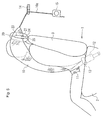
- Fig. 1 is a perspective view of a passenger constraining apparatus according to an embodiment of the invention
- Fig. 2 is a perspective view of a shoulder belt section push-up device in the passenger constraining apparatus
- Fig. 3 is a front view of the push-up device
- Figs. 4(a), (b) are front views of the push-up device in course of pushing up the shoulder belt section and at the completion of pushing up the same respectively
- Fig. 5 is a side view of the passenger constraining apparatus.
- Fig. 5 shows a state in which the shoulder belt section is inflated.
- a vehicle seat 1 includes a seat cushion 2 on which a passenger is seated, a seatback 3 which constitutes a back of the seat, and a head rest 4 provided on top of the seatback 3.
- the seat cushion 2 is formed by mounting a cushion material of urethane or the like on a base frame (not shown) installed on a floor surface of the vehicle.
- the seatback 3 is formed by mounting the cushion material such as urethane or the like on a seatback frame 3a (Fig. 2 to Fig. 4) extending upright from a rear end of the base frame via a reclining device (not shown).
- the passenger constraining apparatus includes a shoulder belt section 10 as an inflatable portion which passes through a lateral side of the passenger's head seated on the seat 1 and drawn obliquely along a front side of an upper body of the passenger (from the upper left to the lower right in this embodiment), a webbing 10a connected to the shoulder belt section 10, a lap belt section 11 drawn in the lateral direction on an upper side of a lumber part of the passenger, a buckle device 12 installed in adjacent on a lateral side (the right side in this embodiment) of the seat 1, a tongue 13 which is inserted into and engaged with the buckle device 12 when attaching the belt, a shoulder anchor 14 for guiding the webbing 10a, a push-up device 20 for pushing up the shoulder belt section 10 provided on an upper portion of the seatback 3 (the left shoulder portion of the seatback 3 in this embodiment), and so on.
- a shoulder belt section 10 as an inflatable portion which passes through a lateral side of the passenger's head seated on the seat 1 and drawn obliquely along a front
- the shoulder belt section 10, the webbing 10a and the lap belt section 11 constitute a passenger constraining belt, and the shoulder belt section 10 forms the inflatable portion.
- the shoulder belt section 10 is inflated from the lateral side of the head to the front side of the upper body of the passenger.
- the shoulder belt section 10 is formed by folding a wide belt-shaped bag into a narrow band shape and covering the same with a cover, and is held in a band shape in the normal state.
- a distal end of the webbing 10a is connected to an upper end side of the shoulder belt section 10 by sewing or the like, and the tongue 13 is joined to a lower end side.
- the webbing 10a is formed of a normal belt similar to a general non-inflatable seatbelt in the related art, and is slidably guided and passed through the shoulder anchor 14. An end of the webbing 10a is retractably joined to a seatbelt retractor (ELR) 15 with an emergency locking mechanism installed on the vehicle.
- ELR seatbelt retractor
- the lap belt section 11 is also formed of a non-inflatable normal belt, and is retractably joined at one end with the tongue 13 and at the other end with a seatbelt retractor (ELR) 16 installed on the seat 1 on the opposite side from the buckle device 12.
- ELR seatbelt retractor
- an inflator 17 which is activated in an urgently needed state such as a vehicle collision to generate high-pressure gas is connected to the buckle device 12, and a passage (not shown) for guiding the gas from the inflator 17 into the shoulder belt section 10 is provided on the tongue 13.
- the push-up device 20 is arranged on an upper surface side of the left shoulder portion on the seatback 3 in this embodiment, and includes a belt guide 21 on which the shoulder belt section 10 is drawn through, guiding members 22 extending downward from the belt guide 21 and supported on the seatback 3 so as to be capable of rising with respect to the seatback 3, a rotating member 23 arranged on the belt guide 21 on an upper side of the shoulder belt section 10, extending in an intersecting direction with the longitudinal direction of the shoulder belt section 10 and rotatably attached to the belt guide 21 at other side (proximal end side) in the extending direction so that one side in the extending direction (distal end side) can rotate upward, a lever section 24 projecting from the proximal end side of the rotating member 23 in the direction of extension of the extending direction of the rotating member 23 so as to rotate downward when the distal end side of the rotating member 23 rotates upward, and an abutment member 25 that is provided on the upper surface of the left shoulder portion of the seatback 3 and abuts the lever section 24 when
- the belt guide 21 has a rectangular plate shape extending in the lateral direction along an upper surface of the left shoulder portion of the seatback 3.
- the belt guide 21 is provided with a pair of holding strips 21a, 21a extending upright for rotatably holding the proximal end side of the rotating member 23 on one end side in the longitudinal direction (the far side from the head rest 4), and a supporting strip 21b extending upright for supporting the distal end side of the rotating member 23 on the other end side (the head rest 4 side).
- the shoulder belt section 10 is drawn from a rear side to a front side of the seatback 3 so as to pass between the holding strip 21a and the supporting strip 21b.
- the rotating member 23 is arranged on an upper side of the belt guide 21 with the extending direction thereof directed in parallel with the longitudinal direction of the belt guide 21, and an end on the side far from the head rest 4 is rotatably held by the holding strips 21a, 21a via an axis of rotation 21c.
- the shoulder belt section 10 when the shoulder belt section 10 is not inflated, the distal end side of the rotating member 23 rests on the supporting strip 21b, and the belt guide 21 and the rotating member 23 constitute a frame-shaped belt guide which is closed over the entire circumference.
- the lever section 24 extends from the proximal end portion of the rotating member 23 in the direction away from the head rest 4 along the upper surface of the seatback 3 in a state in which the distal end side of the rotating member 23 is moved downward and reaches the supporting strip 21b.
- Holding members 26, 26 for holding the respective guiding members 22, 22 so as to be capable of rising are provided on the left shoulder portion of the seatback 3.
- Each holding member 26 is formed into a substantially cylindrical shape having an inner hole (through hole) 26a, and is secured to the frame 3a passing through the left shoulder portion of the seatback 3 with the axial center line of the inner hole 26a oriented in the vertical direction.
- An upper end side of the inner hole 26a of each holding member 26 has an opening on the upper surface of the left shoulder portion of the seatback 3.
- the belt guide 21 is mounted to the seatback 3 so as to be capable of rising by inserting the guiding members 22 into the inner holes 26a of the holding members 26.
- the upper end sides of the holding members 26 are slightly projected from the upper surface of the seatback 3, and flanges (reference numerals are omitted) are radially extending from the upper end sides of the respective holding members 26 along the upper surface of the seatback 3.
- the abutment member 25 is formed by extending the flange of the holding member 26 on the side far from the head rest 4 in the direction away from the head rest 4. This abutment member 25 faces the lever section 24 from below.
- a stopper groove 25a is formed on an upper surface of the abutment member 25 for allowing a distal end side of the lever section 24 to engage when the lever section 24 is rotated downward until it abuts on the abutment member 25 and then is further rotated to a posture in which the belt guide 21 is pressed upward to a predetermined height.
- the passenger constraining belt is used in the same manner as the normal seatbelt.
- the belt guide 21 of the push-up device 20 and the rotating member 23 function as the belt guide.
- gas is introduced into the shoulder belt section 10, and as shown in Figs. 4 and 5, the shoulder belt section 10 is inflated as it increases the thickness (diameter).
- the shoulder belt section 10 is pushed upward by the belt guide 21, and as shown in Fig. 5, the inflated shoulder belt section 10 is placed at a high position on the lateral side of the passenger's head.
- the shoulder belt section 10 since the shoulder belt section 10 is pushed up by the push-up device 20 provided on the upper surface side of the seatback 3, the inflated shoulder belt section 10 can be placed at a high position on the lateral side of the passenger's head without using a high-output inflator.
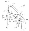
- Fig. 6 is a front view of a push-up device 20A configured in this manner showing a state of pushing up the inflatable portion of the push-up device 20A.
- a holding member 26A for holding one of the guiding members 22A of the belt guide 21 so as to be capable of rising is provided with a ratchet mechanism 30 for preventing the raised guiding member 22A from retracting downward.
- the ratchet mechanism 30 is provided with a claw 31 projecting into the inner hole 26a of the holding member 26A by an urging force of a spring (reference numeral is omitted), and grooves 32 which the claw 31 is engaged with is formed on a side surface of the guiding member 22A.
- the plurality of grooves 32 are provided on the guiding member 22A at different positions in the extending direction (vertical direction) of the guiding member 22A.
- the ratchet mechanism 30 is configured to cause the claw 31 to retract from the groove 32 to allow the rising movement of the guiding member 22A when the guiding member 22A rises and allow the rising movement of the guiding member 22A and to cause the claw 31 not to retract from the groove 32 and prevent the downward movement of the guiding member 22A when the guiding member 22A tries to move downward.
- the stopper groove which the lever section 24 engages with is not provided on an upper surface of an abutment member 25A.
- FIG. 1 Other configurations of the push-up device 20A are the same as the push-up device 20 in Figs. 1 to 5 described above, and the same reference numerals as Figs. 1 to 5 in Fig. 6 designate the same portions.
- the ratchet mechanism 30 prevents the guiding member 22A from retracting downward. Therefore, the inflated shoulder belt section 10 and the belt guide 21 which rotatably supports the shoulder belt section 10 is maintained in a state of being raised to a high position on the lateral side of the passenger's head.
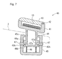
- Fig. 7 to Fig. 9 show the push-up device of the passenger constraining apparatus according to the embodiments described in Claims 6 and 7, in which Fig. 7 shows a state in which the belt guide is in a stationary state; Fig. 8 shows a state in which the belt guide is pushed downward; and Fig. 9 shows a state in which the belt guide is pushed upward.
- the shoulder belt section 10 as the inflatable portion is formed by folding the wide belt-shaped bag into the narrow band shape and covering the same with the cover, and is held in the band shape in the normal state in the same manner as the above-described embodiment.
- a push-up device 40 is arranged on the upper surface side of the left shoulder portion of the seatback 3, and includes a belt guide 41 on which the shoulder belt section 10 is drawn through, a top cover 43 rotatably attached to the belt guide 41 via a supporting shaft 42, a guiding member 44 extending downward from the belt guide 41, a holding member 45 for supporting the guiding member 44 so as to be capable of rising, a coil spring 46 serving as urging means for urging the guiding member 44 upward, lock pins 47 serving as locking means for preventing the guiding member 44 from rising, and the like on the upper side thereof.
- the belt guide 41 has an upwardly opening angular C-shape, and the top cover 43 is provided on an upper side of the shoulder belt section 10 so as to straddle the belt guide 41.
- the belt guide 43 is pushed upward and rotates in the upright direction when the shoulder belt section 10 is inflated. It is also possible to urge the top cover 43 in the tilt-down direction by a magnet or a spring.
- the guiding member 44 has a bottomed cylindrical shape, and is coaxially inserted into the holding member 45 having the bottomed cylindrical shape with the direction of axial center of the cylinder oriented in the vertical direction from above.
- the spring 46 is interposed between a bottom surface of the holding member 45 and a bottom surface of the guiding member 44 in a pressure-accumulated state.
- a lower flange section 44b and an upper flange section 44a of an outwardly extending flange shape are projected from two points; a lower end portion of the guiding member 44 and a position slightly upward therefrom.
- a plurality of supporting holes 45h for the lock pins 47 are provided on a side periphery of the holding member 45 at intervals in the circumferential direction, and the lock pins 47 are inserted into the supporting holes 45h so as to be capable of coming in and out.
- Distal end sides of the lock pins 47 project from an inner peripheral surface of the holding member 45, and are inserted between the upper flange section 44a and the lower flange section 44b.
- An upper surface of the distal end side of the lock pin 47 is formed into an inclined surface 47a which is inclined downwardly toward the distal end.
- An outer peripheral end of the upper flange section 44a is placed above the inclined surface 47a.
- a lower surface of the lock pin 47 is substantially horizontal.
- An inward flange-shaped stopper section 45s is provided on an upper end of the holding member 45.
- Fig. 10(a) shows a push-up device 40A according to the embodiment in such a structure, and is a vertical cross-section taken along the same plane as in Fig. 7.
- an upper flange section 45a and a lower flange section 45b are provided on the upper and lower stages on the inner peripheral surface of the holding member 45.
- the guiding member 44 is formed with supporting holes 44h for the lock pins 47.
- the lock pins 47 are slidably inserted into the supporting holes 44h, and distal end sides thereof are inserted between the upper flange section 45a and the lower flange section 45b.
- a lower surface of the lock pin 47 on a distal end side is formed into the inclined surface 47a inclining upward toward the distal end.
- An inner peripheral end of the lower flange section 45b is placed downwardly of the inclined surface 47a.
- the lock pins 47 abut on the upper flange section 45a from below.
- the guiding member 44 is provided with the upper flange section 44a, but is not provided with the lower flange section 44b.
- the upper flange section 44a is provided upwardly of the upper flange section 45a of the holding member 45 by a predetermined distance.
- Other configurations are the same as those in Fig. 7, and the same parts are represented by the same reference numerals.
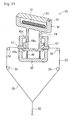
- Fig. 11 is a block diagram of a push-up device 40 with a wire
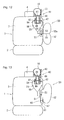
- Fig. 12 is a general block diagram of a seat
- Fig. 13 is a general block diagram of the seat in a case in which an actuator is mounted to the side airbag apparatus.
- a side airbag apparatus 50 is installed in the seatback 3.
- the side airbag apparatus 50 includes a case 51 installed on a side surface portion of the seatback 3, a side airbag 52 stored in the case 51, an inflator 53 for inflating the side airbag 52 toward the lateral side of passenger as shown in the drawing, and so on.
- a distal end side 52a of the side airbag 52 in the inflating direction and the lock pins 47 are connected via a wire 55.
- Reference numeral 56 designates a jig for guiding the wire.
- the shoulder belt section 10 and the side airbag 52 are inflated in case of vehicle side collision.
- the inflator 53 is activated and the side airbag 52 is inflated, the wire 55 is pulled by the distal end side 52a of the side airbag 52 in the inflating direction, and the lock pins 47 are retracted. Accordingly, the belt guide 41 and the guiding member 44 rise until the engagement between the lock pin 47 and the lower flange section 44b are released, and the upper flange section 44a comes into abutment with the stopper section 45s, and the shoulder belt section 10 in the inflated state is maintained at a high position.
- an actuator 60 of a gas cylinder type for pulling the wire 55 by a gas pressure generated from the inflator 53 is provided in the side airbag apparatus 50.
- the actuator 60 is connected at one end to the case 51, and includes a cylinder 61 to which gas from the inflator 53 is introduced therein and a piston 62 arranged in the cylinder 61. A distal end of the wire 55 is connected to the piston 62.
- the passenger constraining belt is configured in such a manner that only the shoulder belt section 10 is inflated.
- a configuration in which the lap belt section 11 is also inflated is also applicable.
- the passenger constraining belt may be configured to be inflated only on the lateral side of the passenger's head.
- the gas supply system for the inflatable portion, the retracting system for the case in which the belt is not attached, the belt passage structure of the tongue or a through anchor of the passenger constraining belt may be of configurations other than those shown in the drawings.
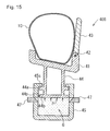
- Fig. 14 and Fig. 15 are cross-sectional views showing an example of the push-up device configured in this manner.
- Fig. 14 shows a state before the push-up device pushes the inflatable portion
- Fig. 15 shows a state in the inflatable portion is pushed up.
- a push-up device 40B in this embodiment has a configuration in which compressed gas G is filled in an air chamber instead of interposing the spring 46 between the bottom surface (lower flange section 44b) of the guiding member 44 and the bottom surface of the holding member 45 in the push-up device 40 shown in Fig. 7 to Fig. 9 described above.
- Reference numeral 44p designates a packing interposed between a side peripheral surface of the lower flange section 44b at a lower end of the guiding member 44 and the inner peripheral surface of the holding member 45.
- air is used as compressed gas G.
- gas other than air can be used.
- FIG. 7 to Fig. 9 Other configurations of the push-up device 40B are the same as the push-up device 40 shown in Fig. 7 to Fig. 9, and the reference numerals in Fig. 14 and Fig. 15, which are the same as those in Figs. 7 to 9 represent the same parts.
- An operating state of the push-up device 40B (for example, lock releasing operation of the lock pins 47) is the same as that in the embodiment shown in Fig. 7 to Fig. 9, and description will be omitted.
- the compressed gas G is filled in the holding member 45 in advance.
- an inflator gas generator
- the inflator is activated to eject gas when the lock by the lock pins 47 is released, whereby the guiding member 44 rises by the gas pressure.
Landscapes
- Engineering & Computer Science (AREA)
- Mechanical Engineering (AREA)
- Air Bags (AREA)
Applications Claiming Priority (3)
| Application Number | Priority Date | Filing Date | Title |
|---|---|---|---|
| JP2005278164A JP4581942B2 (ja) | 2005-09-26 | 2005-09-26 | 乗員拘束装置 |
| JP2005278172 | 2005-09-26 | ||
| JP2006050537A JP4775032B2 (ja) | 2005-09-26 | 2006-02-27 | 乗員拘束装置 |
Publications (3)
| Publication Number | Publication Date |
|---|---|
| EP1767412A2 true EP1767412A2 (de) | 2007-03-28 |
| EP1767412A3 EP1767412A3 (de) | 2008-04-09 |
| EP1767412B1 EP1767412B1 (de) | 2010-01-20 |
Family
ID=37526956
Family Applications (2)
| Application Number | Title | Priority Date | Filing Date |
|---|---|---|---|
| EP20060019791 Ceased EP1767412B1 (de) | 2005-09-26 | 2006-09-21 | Beifahrer-Rückhaltevorrichtung |
| EP06019788A Withdrawn EP1767411A3 (de) | 2005-09-26 | 2006-09-21 | Beifahrer-Rückhaltevorrichtung |
Family Applications After (1)
| Application Number | Title | Priority Date | Filing Date |
|---|---|---|---|
| EP06019788A Withdrawn EP1767411A3 (de) | 2005-09-26 | 2006-09-21 | Beifahrer-Rückhaltevorrichtung |
Country Status (2)
| Country | Link |
|---|---|
| EP (2) | EP1767412B1 (de) |
| DE (1) | DE602006011831D1 (de) |
Cited By (1)
| Publication number | Priority date | Publication date | Assignee | Title |
|---|---|---|---|---|
| EP1818223A3 (de) * | 2006-02-09 | 2008-09-24 | Takata Corporation | Luftgurtvorrichtung für ein Kraftfahrzeug |
Citations (1)
| Publication number | Priority date | Publication date | Assignee | Title |
|---|---|---|---|---|
| JP2003312439A (ja) | 2002-04-23 | 2003-11-06 | Honda Motor Co Ltd | エアベルト装置 |
Family Cites Families (6)
| Publication number | Priority date | Publication date | Assignee | Title |
|---|---|---|---|---|
| DE4218792A1 (de) * | 1992-06-06 | 1993-12-09 | Bayerische Motoren Werke Ag | Dreipunktsicherheitsgurtsystem für Kraftfahrzeuge |
| DE69732294T2 (de) * | 1996-07-02 | 2005-12-22 | Zodiac Automotive Us Inc., Tempe | Aufblasbares schlauchartiges rumpf-rückhaltesystem |
| US5829841A (en) * | 1997-12-16 | 1998-11-03 | General Motors Coporation | Inflatable seat belt tensioner |
| US6145881A (en) * | 1999-01-15 | 2000-11-14 | Breed Automotive Technology Inc. | Seatback mounted seat belt tensioner |
| DE19950951A1 (de) * | 1999-10-22 | 2001-04-26 | Bayerische Motoren Werke Ag | Aufblasbarer Sicherheitsgurt |
| JP4458387B2 (ja) * | 2000-02-28 | 2010-04-28 | タカタ株式会社 | インフレータブルシートベルト装置 |
-
2006
- 2006-09-21 EP EP20060019791 patent/EP1767412B1/de not_active Ceased
- 2006-09-21 DE DE200660011831 patent/DE602006011831D1/de active Active
- 2006-09-21 EP EP06019788A patent/EP1767411A3/de not_active Withdrawn
Patent Citations (1)
| Publication number | Priority date | Publication date | Assignee | Title |
|---|---|---|---|---|
| JP2003312439A (ja) | 2002-04-23 | 2003-11-06 | Honda Motor Co Ltd | エアベルト装置 |
Cited By (2)
| Publication number | Priority date | Publication date | Assignee | Title |
|---|---|---|---|---|
| EP1818223A3 (de) * | 2006-02-09 | 2008-09-24 | Takata Corporation | Luftgurtvorrichtung für ein Kraftfahrzeug |
| US7740271B2 (en) | 2006-02-09 | 2010-06-22 | Toyota Jidosha Kabushiki Kaisha | Air belt apparatus for motor vehicle |
Also Published As
| Publication number | Publication date |
|---|---|
| DE602006011831D1 (de) | 2010-03-11 |
| EP1767412A3 (de) | 2008-04-09 |
| EP1767411A2 (de) | 2007-03-28 |
| EP1767411A3 (de) | 2008-04-09 |
| EP1767412B1 (de) | 2010-01-20 |
Similar Documents
| Publication | Publication Date | Title |
|---|---|---|
| US7584990B2 (en) | Passenger constraining apparatus | |
| US9919673B2 (en) | Vehicle occupant protection device | |
| CN107284391B (zh) | 乘员保护装置 | |
| US6592146B2 (en) | Variable profile air bag restraint | |
| US6736426B2 (en) | Variable profile air bag restraint | |
| JP5286765B2 (ja) | 乗員拘束装置 | |
| EP1568537B1 (de) | Insassenschutzeinrichtung | |
| US6832778B2 (en) | Air bag restraint including selectively operable venting elements | |
| US6454300B1 (en) | Air bag tether release assembly | |
| JP6383176B2 (ja) | エアバッグ及びエアバッグ装置 | |
| JP5426157B2 (ja) | 衝突前及び衝突時のデュアルモードで展開するエアバッグ・クッション | |
| US7905514B2 (en) | Motor vehicle safety restraint system | |
| US8408594B2 (en) | Airbag | |
| US5829841A (en) | Inflatable seat belt tensioner | |
| US11208070B1 (en) | Airbag system and method(s) of use thereof | |
| US20200254953A1 (en) | Modular restraint seat for vehicle with one or more integrated safety features | |
| JP4174515B2 (ja) | 車両用エアベルト装置 | |
| CN102649415A (zh) | 乘员保护装置 | |
| JP2018135016A (ja) | 乗員拘束装置及び座席 | |
| JP6751581B2 (ja) | 乗員保護装置 | |
| US20200189510A1 (en) | Airbag including inflation chamber | |
| EP1767412B1 (de) | Beifahrer-Rückhaltevorrichtung | |
| US7566072B2 (en) | Occupant restraining apparatus | |
| JP6512697B2 (ja) | 乗員保護装置 | |
| JP2022030821A (ja) | 乗員保護装置及び車両用シート |
Legal Events
| Date | Code | Title | Description |
|---|---|---|---|
| PUAI | Public reference made under article 153(3) epc to a published international application that has entered the european phase |
Free format text: ORIGINAL CODE: 0009012 |
|
| AK | Designated contracting states |
Kind code of ref document: A2 Designated state(s): AT BE BG CH CY CZ DE DK EE ES FI FR GB GR HU IE IS IT LI LT LU LV MC NL PL PT RO SE SI SK TR |
|
| AX | Request for extension of the european patent |
Extension state: AL BA HR MK YU |
|
| PUAL | Search report despatched |
Free format text: ORIGINAL CODE: 0009013 |
|
| AK | Designated contracting states |
Kind code of ref document: A3 Designated state(s): AT BE BG CH CY CZ DE DK EE ES FI FR GB GR HU IE IS IT LI LT LU LV MC NL PL PT RO SE SI SK TR |
|
| AX | Request for extension of the european patent |
Extension state: AL BA HR MK RS |
|
| 17P | Request for examination filed |
Effective date: 20080827 |
|
| 17Q | First examination report despatched |
Effective date: 20081027 |
|
| AKX | Designation fees paid |
Designated state(s): DE GB |
|
| GRAP | Despatch of communication of intention to grant a patent |
Free format text: ORIGINAL CODE: EPIDOSNIGR1 |
|
| GRAS | Grant fee paid |
Free format text: ORIGINAL CODE: EPIDOSNIGR3 |
|
| GRAA | (expected) grant |
Free format text: ORIGINAL CODE: 0009210 |
|
| AK | Designated contracting states |
Kind code of ref document: B1 Designated state(s): DE GB |
|
| REG | Reference to a national code |
Ref country code: GB Ref legal event code: FG4D |
|
| REF | Corresponds to: |
Ref document number: 602006011831 Country of ref document: DE Date of ref document: 20100311 Kind code of ref document: P |
|
| PLBE | No opposition filed within time limit |
Free format text: ORIGINAL CODE: 0009261 |
|
| STAA | Information on the status of an ep patent application or granted ep patent |
Free format text: STATUS: NO OPPOSITION FILED WITHIN TIME LIMIT |
|
| 26N | No opposition filed |
Effective date: 20101021 |
|
| PGFP | Annual fee paid to national office [announced via postgrant information from national office to epo] |
Ref country code: GB Payment date: 20130918 Year of fee payment: 8 |
|
| GBPC | Gb: european patent ceased through non-payment of renewal fee |
Effective date: 20140921 |
|
| PG25 | Lapsed in a contracting state [announced via postgrant information from national office to epo] |
Ref country code: GB Free format text: LAPSE BECAUSE OF NON-PAYMENT OF DUE FEES Effective date: 20140921 |
|
| REG | Reference to a national code |
Ref country code: DE Ref legal event code: R082 Ref document number: 602006011831 Country of ref document: DE Representative=s name: KRAUS & WEISERT PATENTANWAELTE PARTGMBB, DE Ref country code: DE Ref legal event code: R081 Ref document number: 602006011831 Country of ref document: DE Owner name: JOYSON SAFETY SYSTEMS JAPAN K.K., JP Free format text: FORMER OWNER: TAKATA CORP., TOKIO/TOKYO, JP |
|
| PGFP | Annual fee paid to national office [announced via postgrant information from national office to epo] |
Ref country code: DE Payment date: 20180920 Year of fee payment: 13 |
|
| REG | Reference to a national code |
Ref country code: DE Ref legal event code: R119 Ref document number: 602006011831 Country of ref document: DE |
|
| PG25 | Lapsed in a contracting state [announced via postgrant information from national office to epo] |
Ref country code: DE Free format text: LAPSE BECAUSE OF NON-PAYMENT OF DUE FEES Effective date: 20200401 |