EP1767362A2 - Device for accomplishing a roll change and the machine equipped with this device - Google Patents
Device for accomplishing a roll change and the machine equipped with this device Download PDFInfo
- Publication number
- EP1767362A2 EP1767362A2 EP20060019019 EP06019019A EP1767362A2 EP 1767362 A2 EP1767362 A2 EP 1767362A2 EP 20060019019 EP20060019019 EP 20060019019 EP 06019019 A EP06019019 A EP 06019019A EP 1767362 A2 EP1767362 A2 EP 1767362A2
- Authority
- EP
- European Patent Office
- Prior art keywords
- roller
- hubarmstruktur
- sheet
- fed printing
- printing machine
- Prior art date
- Legal status (The legal status is an assumption and is not a legal conclusion. Google has not performed a legal analysis and makes no representation as to the accuracy of the status listed.)
- Withdrawn
Links
Images

Classifications
-
- B—PERFORMING OPERATIONS; TRANSPORTING
- B41—PRINTING; LINING MACHINES; TYPEWRITERS; STAMPS
- B41F—PRINTING MACHINES OR PRESSES
- B41F31/00—Inking arrangements or devices
- B41F31/30—Arrangements for tripping, lifting, adjusting, or removing inking rollers; Supports, bearings, or forks therefor
Definitions
- the invention relates to a device for accomplishing a roll change in a paint or coating unit of a sheet-fed printing machine with a lifting device comprising a left Hubarm réelle and a right Hubarm Modell.
- This device serves to displace a roller which can be exchanged into the printing press between a working position and a storage position, in particular for removal or replacement of that roller.
- the invention further relates to a printing machine which is equipped with such a roll changing device.
- Out DE 199 62 425 B4 is a device for changing an anilox roller of a coating unit of a printing press with a Hubarmportal known. About this Hubarmportal an anilox roller can be taken in the region of its working position and initially raised in the vertical direction. Subsequently, the angled roller thus grasped and raised can be displaced in a horizontal direction in a region lying between the side frames of the printing press and deposited on a first or a second storage position adjacent thereto.
- a coating unit for rotary printing presses which is provided with a rotary magazine, in which a plurality of anilox rollers can be stored.
- the rotary magazine is provided with a cable pulling device, via which an anilox roller can be lowered from a downwardly pointing magazine compartment and moved partially manually into a working position.
- a chambered doctor blade coating unit is known, the Includes rotary magazine, in which a plurality of anilox rollers are rotatably mounted.
- the roller bearings of the rotary magazine form the working bearings of the individual chamber rollers.
- By corresponding pivoting of the rotary magazine it is possible to spend each an anilox roller of the same in a working position in which the anilox roller rests on an associated paint form cylinder.
- the invention has for its object to provide solutions which make it possible to accomplish the change of a paint or other removable roller in a sheet-fed or sheet finishing machine in a particularly advantageous manner.
- the storage device for mounting the lifting device on the side frame of the printing machine can be mounted.
- the assembly can be done by a mounting flange, which is preferably designed as such that it can be mounted on standard frame side provided sections, in particular over standard existing fitting and tapped holes.
- the roll changing device can be designed as a largely self-contained assembly, which can also be used later as part of a machine retrofitting in the manner of an "upgrade package" on montagetechnisch advantageous interfaces in the area lying between the side frames.
- the left lifting arm structure and the right lifting arm structure are preferably designed such that the radial distance of the changing roller from the pivot axis is variable.
- the pivot axis is preferably located above the working position of the removable roller.
- the left lift arm structure and the right lift arm structure may be formed so that they are retractable, for lifting out the roller to be changed.
- the left lift arm structure and the right lift arm structure are further extendable radially to the pivot axis to insert the exchange roller in the working position.
- the left and right Hubarminnate may be provided with gripping structures, in particular gripping heads to seize the change roller in the region of the axial ends, in particular bearing journals thereof.
- the left and right Hubarm aged can each form parts of a multi-arm Hubarmsterns.
- This Hubarmstern can comprise two diametrically opposed Hubarm Modellen, so that simultaneous handling of the roller to be inserted and the roller to be replaced is made possible.
- the lifting arm star can also carry other Hubarm Modellen, in particular three, or four arms be formed.
- the control of the roll changing device can be carried out so that at least several phases in a plurality of rollers carried by this and this case, if necessary, also stored.
- the lifting arms are designed according to a particularly preferred embodiment of the invention as a multi-stage telescopic cylinder.
- the telescopic cylinders are connected to the Hubarmstern or the central hub device such that the outer cylinder are in the region of the inner cylinder connection, whereas the piston rods are guided outwardly movable in these outer cylinders.
- the telescopic cylinders can be designed as pressure medium, in particular pressure oil actuated hydraulic cylinder. Alternatively, or in combination with this measure, the telescopic cylinder can also be designed as a spindle, in particular ball screw cylinder.
- the cylinders of a Hubarmsystems are preferably synchronized by means of a synchronization device such that no inadmissible tilting or tilting of the corresponding roller occurs in the context of lifting or lowering.
- the synchronization is preferably realized by mechanical coupling systems such as spindles, link chains, timing belt or handlebars. Alternatively, it is also possible to metrologically detect the stroke state of the roller or the instantaneous radial stroke of the respective arm and make Hubkorrekturen based on regulatory approaches.
- the lifting arms can also be designed as articulated arms, in particular buckling, or scissor articulated arms.
- the buckling can take place within an axial plane which includes the pivot axis of the system. It is also possible, the Hubarm adopted be executed so that the buckling of the lifting arms takes place in each case in a plane radial to the pivot axis of the Hubarmsystems.
- the control of the changing device can be carried out such that at least in phases lifting and pivoting movements are performed superimposed each other.
- the roller grasped by the lifting arm systems can be moved on a path which is optimized with regard to its course.
- the trajectory can be optimized in addition to the consideration of the criterion of collision avoidance, taking into account the mass forces and the time required.
- control technology bewerkstelligbar with less effort, it is possible to operate the system so that initially only each to be handled roller is displaced radially by the cross-arm this cross-arm system relative to the pivot axis and pivoting takes place only when the roller is tightened.
- the initiation of the movements is preferably carried out with a soft start, so that excessive start-up and Abbremsst Kunststoffe be avoided.
- a sheet-fed press On the basis of the above-mentioned inventive concept for a machine-integrated roll changing device, a sheet-fed press is provided.
- This sheet-fed printing machine preferably comprises a bearing device for supporting a changing roller in a working position, wherein the bearing device comprises a roller-clamping device which is selectively engageable in a clamping position and in a release position, wherein in the clamping position, the changing roller is secured in that working position in a rotatably movable manner and can be removed from the storage device in the release position.
- the bearing device can be designed as a backup bearing with unilaterally open receiving shells. Details of this are from the date of the applicant DE 199 62 421 C1 known. It is also possible, the roller and the associated storage or clamping device in such a way that the voltage by axially displaceable Pratzen-, Kochsch-, or otherwise, the respective axial end of the roller bearing engagement structures takes place.
- the lifting arm system can comprise locking and unlocking devices by means of which the clamping device can be actuated.
- the lift arm system may include drive means to rotate the roller in a particular orientation.
- Such an auxiliary drive device can also be integrated into the printing machine as an assembly separate from the lifting arm system.
- roller gripper devices of the Hubarmsysteme can be designed so that they have engagement journal portions which are insertable into a radial opening of the rollers to be changed and temporarily locked therein.
- Such a design of the roller gripper devices is in the date of the applicant DE 199 62 443 C1 described.
- roller gripper devices in such a way that they encompass or grasp the circumference of the roller in the area of axial ends or end pegs.
- the roller can be taken without special consideration of the rotational position thereof.
- the roll change system according to the invention can be designed so that it can be moved between the working position and the storage position by this roller, the web. It is possible, this web-controlled to make a temporary transfer of the roller in an intermediate position in which the roller is accessible to a cleaning device, so that an intermediate cleaning of the roller can be carried out prior to relocation of the same in the storage position. It is also possible to automatically pre-clean the items to be loaded To carry out roll by these brought before moving into the working position in one of the pre-cleaning serving intermediate position and here pre-cleaned, in particular dedusted and cleaned.
- the device according to the invention can be designed such that not only the rollers to be changed but also other functional components of the printing press can be handled by them.
- the device according to the invention can in particular be designed such that it also cleans devices, in particular a cleaning module, or other components of a coating unit, e.g. a chamber doctor device is handled within the printing machine, or e.g. can be moved to a release position.
- a plurality of lifting arms which have different and adapted to the respective hand-to-handle system component gripper or handling heads.
- the storage position may be located in a roll storage area or represent a transfer position upstream of this.
- the roll storage area is preferably located at a location easily accessible to a user in the upper area of the printing press.
- the roll storage area can be located in particular above the upper machine panel.
- a tub device may be provided, in which any media draining from the rollers can be collected.
- a transfer magazine device can be provided in the roll storage area, in which the rolls can be stored in a defined manner and moved in a controlled manner into a position provided for take-up.
- the storage area and the path space accessible to the moving structures can be protected by detection organs, so that, for example, when an intrusion, in particular intervention of a user in the observed area, the issuing of a warning signal or a shutdown of the changing device takes place.
- detection devices can be implemented by incorporating optical means, in particular light barriers, thermal imaging systems or proximity sensors. Instead of a full shutdown of the hazardous Systems can also be switched to an operating mode, for example, the speed of movement of the moving components is lowered, or, for example, provides more sensitive shutdown criteria. It is possible to provide display means by which the user is signaled that he is close, or possibly in an observed area, so that if necessary, the user can still withdraw from the observed area before a safety operating mode of the changing device is controlled.
- the rollers can be equipped with an automatically readable coding or in particular with an optically or otherwise electromagnetically readable data carrier, from which roll-specific information can be read out or possibly also written down.
- a read or write head provided for data transfer can be integrated in the device according to the invention and positioned accordingly.
- the pivot drive of the Hubarmsystems can be designed so that an alternating pivoting or a successive further rotation of the Hubarmsystems done. Activation of the rotary actuator Success preferably program-based according to selectable procedures. It is possible to carry out the control of the changing device from a machine control station. Alternatively, or in combination with this measure, a control from the immediate vicinity of the corresponding printing or coating unit can take place. In particular, in a control from the immediate environment, the individual processes, in particular the pivoting of the Hubarmsystems, lowering or raising the roller in or out of the working position and unlocking the roller tension are performed so slowly that the operator side a visual control of the process and possibly intervention is possible.
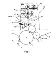
- Figure 1 shows a roll changing device for effecting the change of a here designed as an anilox roll changing roller 1 in a coating unit 2 a sheetfed press.
- the sheet-fed press comprises in a conventional manner a sheet feed table 3, a pre-gripper 4 and a here with a double-sized cylinder 6 cooperating transfer cylinder 5.
- a paint form cylinder 7 On the cylinder 6 runs a paint form cylinder 7.
- the over the paint form cylinder 7 lacquered sheet is from the cylinder. 6 transferred to a drum 8.
- the running direction of the sheet is indicated in Figure 1 by small arrow symbols.
- the chambered scraper device 9 is movably supported by a pivoting mount 10 in such a way that the chambered scraper device 9 can be brought into a release position, as indicated by the arrow symbol P1, in which a subsequent removal or insertion of the exchangeable roller 1 into the working position I is made possible.
- the actual coating unit 2 is located below a cover 11.
- the cover 11 is formed such that it temporarily exposes a window section 12 through which the replacement roller 1 can be moved into the enclosed area or out of it.
- the roll changing device integrated in the printing press 13 comprises a lifting arm device 14 which comprises a left lift arm structure 15 and a right lift arm structure 16 (see FIG. 4).
- the Hubarm annoyed 14 allows a displacement of the removable roller 1 between a working position I and a storage position III.
- the roller changing device further comprises a bearing device 17 for supporting the Hubarm Hughes 14 in a pivotable manner about a pivot axis S, which is aligned substantially parallel to the axis of rotation of the roller 1 to be changed.
- the pivot axis S passes through an intermediate region, which is located in the vertical direction between the working position I and the storage position III of the removable roller.
- the storage device 17 for mounting the Hubarm acknowledged 14 is mounted on the side frame of the printing press 13.
- the left Hubarm réelle 15 and the right Hubarm réelle 16 are formed such that the radial distance of the exchange roller 1 from the pivot axis S is changed by appropriate control of the roll changing device.
- the pivot axis S is located above the working position I of the change roller I. To lift out the change roller 1, the two Hubarm Modellen 15, 16 are retracted, so that the change roller 1, the pivot axis S approaches.
- the Hubarm Medical 15, 16 are pivoted about the pivot axis S, so that the change roller here comes into positions II or IV.
- the changing roller can optionally be treated automatically, in particular cleaned.
- the lifting of the removable roller 1 is carried out by being gripped in the region of its axial ends.
- the Hubarm Geneva 15, 16 are provided for this purpose in the region of its outer ends with gripping structures for gripping the removable roller.
- the Hubarmregalen 15, 16 may form part of a multi-arm Hubarmsterns.
- the Hubarm Profen are executed in the embodiment shown as a telescopic cylinder.
- the sheet-fed printing machine 13 equipped with the aforementioned roll changing device is provided in the region of the bearing point of the exchange roll 1 with a clamping device which can be brought selectively into a clamping position and into a release position.
- a clamping device which can be brought selectively into a clamping position and into a release position.
- the change roller 1 is secured in that working position I in a rotatably movable manner.
- the release position the removable roller 1 can be removed from the associated storage system.
- the storage system can be designed for this purpose as a catch bearing with unilaterally open receiving shells.
- the storage position III is located in an upper roll storage area WAB in which several removable rollers can be stored. It is possible to provide here a magazine device through which the rollers are movable into a Aufgriffswolf suitable for engagement by the Hubarm Modellen 15, 16 Aufgriffswolf.
- the rolls accommodated there are preferably supported in the area of their bearing journals. These journals can hereby rest on both sides vorgesehen bearing tracks 18.
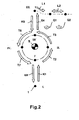
- the roll transfer which can be accomplished within the printing machine by means of the roll changing device according to the invention is illustrated schematically in FIG.
- the Hubarmstern is first pivoted about the pivot axis S such that the provided for lifting the roller 1 Hubarmcru is directed to the roller 1 out. Subsequently, the Hubarmcru is lengthened until the gripper heads of the same engage in corresponding opposite sections of the roller 1. The roller 1 is now unlocked in the area of their bearings, so that it is released for subsequent lifting. In parallel with this, an application device, in particular a chamber doctor device, possibly resting on the roller 1 can be lifted off the roller 1.
- the pair of lifting arms is pivoted in accordance with the arrow T2 so that the roller 1 reaches the position II. In this position, or in an adjacent position, the roller 1 can be supplied to a cleaning device.
- the roller can be released and move in a substantially horizontal direction to a storage position, as indicated by the arrows L1, L2. It is possible to move the roller to a certain storage position by positioning aids or e.g. To support a belt or chain drive, so that the final storage position is achieved positively controlled.
- the roller For automated picking up of a roller from the upper area of the printing press, the roller is first moved to position III. There she is picked up by a Hubarmcru. The now gripped roller is lowered as indicated by the arrow K5, by the lifting arms are retracted.
- the lifting arm system is pivoted (arrow T6) until the roller reaches position IV.
- the roll to be loaded can be pretreated as required, e.g. Dedusted and cleaned.
- the roller is further pivoted (arrow T7) until it reaches the position I '.
- the roller is above the working position I.
- the roller is lowered by expanding the lifting arms in the working position I.
- the receiving mounts provided for receiving the roll end pegs are brought into a receiving state, which allows a sinking of the roll.
- the roll is stored in the receiving warehouse, e.g. tensioned by axial insertion of a locking member.
- a chamber doctor blade device are made to the roller.
- FIG 3 a sketchy a Hubarmsystem is shown, which has only one lift arm 15 (A-side) and 16 (B-side) for each frame side.
- the lifting arm is designed as a telescopic cylinder. It is possible to design and arrange the cylinder so that it passes through the pivot axis S and projects rearwardly beyond the hub region 15N. The supernatant can be dimensioned so that this almost corresponds to the radial distance of the tip of the gripping head 18 of the pivot axis S in the retracted state.
- FIG. 3b shows a two-armed variant of the lifting arm system.
- the lifting arms 15A, 15B are arranged diametrically opposite one another.
- FIG. 3c shows a three-armed variant.
- the lift arms 15A, 15B and 15C are mounted at the same circumferential pitch on the hub portion 15N. It is possible to otherwise define the pitch and thus correlate certain rotational positions of the Hubarmsystems and positions of transfer and possibly treatment stations.
- FIG 3d a three-armed variant is shown.
- the Hubarmsystem can act as an intermediate magazine, in which three rollers can be stored and still a Hubarmcru for lifting the roller from the working position is available.
- FIG. 4 shows in sketch form the position of a Einarmsystems according to Figure 3a within a printing press.
- the A- and B-side frames adjacent lifting arms 15, 16 are connected to each other via a cross-beam 19.
- the cross-beam 19 is designed here as a relatively torsionally rigid structure and extends concentrically to the pivot axis S.
- the cross-beam 19 may also be formed as a bow-like structure, which in this case extends offset on a lifting arms 15, 16 side facing away from the pivot axis.
- a pivot drive via which, for example via a torsion cylinder, a required for pivoting the Hubarmportals drive torque can be applied.
- the device according to the invention is particularly suitable for use in sheet-fed rotary printing presses with flexographic printing or coating units in chamber doctor blade / screen rolling technology. It is also particularly suitable for sheet-fed offset printing presses with upstream, downstream and intermediate lacquer or flexo-works for in-line finishing or pre-coating.
- a machine-integrated handling device (in particular a machine-integrated anilox roller changing machine) which provides component transfer with high dynamics allows.
- the device according to the invention is preferably actuated partially automatically from the control station, either fully automatically or also near the module, possibly under the control of the operator.
- the storage structures provided for incorporation into the printing press are preferably fixed to the side stand fixed to the A and B sides of the printing press.
- the lifting arms can be realized as a telescoping cylinder system extending and retracting vertically.
- the drive of the same is preferably carried out pneumatically.
- the drive of the lift arms can also be hydraulically or otherwise mechanically, e.g. via Kugelgewinde- or parent structures.
- lifting bolts or other catching devices e.g. Ball locking bolt, in particular ball release lock bolts be provided, which engage in the cylinder side provided pin bores and can be locked in this pin bore.
- the disengagement of the balls can be done by pins which are movable in the axial direction within the Aushebebolzens and disengage the associated balls via a shoulder device in the radial direction.
- the engagement of the rollers can also be done by other gripper or hook systems.
- the movement sequence can be protected by protective systems.
- the course of the opening of the machine protection for the passage of the roller can be controlled so that only briefly and only a sufficient opening of the protection takes place.
- the lagklemmung can be automated in terms of process or automatically canceled or caused by special design of the mechanics.
- the rollers can be arranged displaceably.
- a cleaning station alternatively, at least one cleaning trough can be arranged.
- the device according to the invention also makes it possible to handle the change of large rolls by shortening one-man operation by one-man operation.
- the device according to the invention can be adapted to a wide variety of format widths and series with minimal modification requirements. Due to the small space requirement, it can be integrated into existing printing press concepts without changing the side stand contour and changing the lateral machine protection.
Abstract
Description
Die Erfindung betrifft eine Vorrichtung zur Bewerkstelligung eines Walzenwechsels bei einem Farb- oder Lackwerk einer Bogendruckmaschine mit einer Hubeinrichtung, die eine linke Hubarmstruktur und eine rechte Hubarmstruktur umfasst. Diese Vorrichtung dient der Verlagerung einer in die Druckmaschine wechselbar eingebundenen Walze zwischen einer Arbeitsposition und einer Ablageposition, insbesondere zur Aus- oder Einwechselung jener Walze. Die Erfindung betrifft weiterhin auch eine Druckmaschine, die mit einer derartigen Walzenwechselvorrichtung ausgestattet ist.The invention relates to a device for accomplishing a roll change in a paint or coating unit of a sheet-fed printing machine with a lifting device comprising a left Hubarmstruktur and a right Hubarmstruktur. This device serves to displace a roller which can be exchanged into the printing press between a working position and a storage position, in particular for removal or replacement of that roller. The invention further relates to a printing machine which is equipped with such a roll changing device.
Aus
Aus
Aus
Der Erfindung liegt die Aufgabe zugrunde, Lösungen zu schaffen die es ermöglichen, den Wechsel einer Lack- oder anderweitigen Wechselwalze in einer Bogendruck- oder Bogenveredelungsmaschine in einer besonders vorteilhaften Weise zu bewerkstelligen..The invention has for its object to provide solutions which make it possible to accomplish the change of a paint or other removable roller in a sheet-fed or sheet finishing machine in a particularly advantageous manner.
Diese Aufgabe wird erfindungsgemäß gelöst durch eine Walzenwechselvorrichtung zur Bewerkstelligung eines Walzenwechsels bei einem Farb- oder Lackwerk einer Bogendruckmaschine mit:
- einer Hubarmeinrichtung, die eine linke Hubarmstruktur und eine rechte Hubarmstruktur umfasst, zur Verlagerung einer Wechselwalze zwischen einer Arbeitsposition und einer Speicherposition, und
- einer Lagerungseinrichtung zur Lagerung der Hubarmeinrichtung in schwenkbewegbarer Weise um eine Schwenkachse, die im wesentlichen parallel zur Rotationsachse der zu wechselnden Walze ausgerichtet ist, wobei die Schwenkachse durch einen Zwischenbereich verläuft, der sich in vertikaler Richtung betrachtet zwischen der Arbeitsposition und der Speicherposition der Wechselwalze befindet.
- a Hubarmeinrichtung comprising a left Hubarmstruktur and a right Hubarmstruktur, for displacing a removable roller between a working position and a storage position, and
- a bearing means for supporting the Hubarmeinrichtung in a pivotable manner about a pivot axis which is aligned substantially parallel to the axis of rotation of the roller to be changed, wherein the pivot axis passes through an intermediate region which is viewed in the vertical direction between the working position and the storage position of the removable roller.
Gemäß einer besonders bevorzugten Ausführungsform der Erfindung ist die Lagerungseinrichtung zur Lagerung der Hubeinrichtung am Seitengestell der Druckmaschine montierbar. Die Montage kann durch eine Montageflanschstruktur erfolgen, die als solche vorzugsweise so ausgebildet ist, dass diese an standardmäßig gestellseitig vorgesehenen Abschnitten, insbesondere über standardmäßig vorhandene Pass- und Gewindebohrungen montierbar ist. Die Walzenwechselvorrichtung kann als weitgehend in sich geschlossene Baugruppe ausgeführt sein, die auch im Rahmen einer Maschinennachrüstung in der Art eines "Upgrade-Packages" über montagetechnisch vorteilhafte Schnittstellen in den zwischen den Seitengestellen liegenden Bereich nachträglich eingesetzt werden kann.According to a particularly preferred embodiment of the invention, the storage device for mounting the lifting device on the side frame of the printing machine can be mounted. The assembly can be done by a mounting flange, which is preferably designed as such that it can be mounted on standard frame side provided sections, in particular over standard existing fitting and tapped holes. The roll changing device can be designed as a largely self-contained assembly, which can also be used later as part of a machine retrofitting in the manner of an "upgrade package" on montagetechnisch advantageous interfaces in the area lying between the side frames.
Die linke Hubarmstruktur und die rechte Hubarmstruktur sind vorzugsweise derart ausgebildet, dass der Radialabstand der Wechselwalze von der Schwenkachse veränderbar ist. Die Schwenkachse befindet sich vorzugsweise oberhalb der Arbeitsposition der Wechselwalze. Die linke Hubarmstruktur und die rechte Hubarmstruktur können so ausgebildet sein, dass diese an sich einziehbar sind, zum Herausheben der zu wechselnden Walze. Die linke Hubarmstruktur und die rechte Hubarmstruktur sind weiterhin radial zur Schwenkachse ausfahrbar, um die Wechselwalze in die Arbeitsposition einzusetzen.The left lifting arm structure and the right lifting arm structure are preferably designed such that the radial distance of the changing roller from the pivot axis is variable. The pivot axis is preferably located above the working position of the removable roller. The left lift arm structure and the right lift arm structure may be formed so that they are retractable, for lifting out the roller to be changed. The left lift arm structure and the right lift arm structure are further extendable radially to the pivot axis to insert the exchange roller in the working position.
Die linke und die rechte Hubarmeinrichtung können mit Greifstrukturen, insbesondere Greifköpfen versehen sein, um die Wechselwalze im Bereich der Axialenden, insbesondere Lagerzapfen derselben, zu ergreifen. Die linke und die rechte Hubarmeinrichtung können jeweils Teile eines mehrarmigen Hubarmsterns bilden.The left and right Hubarmeinrichtung may be provided with gripping structures, in particular gripping heads to seize the change roller in the region of the axial ends, in particular bearing journals thereof. The left and right Hubarmeinrichtung can each form parts of a multi-arm Hubarmsterns.
Dieser Hubarmstern kann zwei einander diametral gegenüberliegende Hubarmstrukturen umfassen, so dass eine simultane Handhabung der einzuwechselnden und der auszuwechselnden Walze ermöglicht ist. Der Hubarmstern kann auch weitere Hubarmstrukturen tragen, insbesondere drei-, oder vierarmig ausgebildet sein. Die Ansteuerung der Walzenwechselvorrichtung kann so erfolgen, dass zumindest phasenweise mehrere Walzen von dieser getragen und hierbei ggf. auch zwischengelagert werden.This Hubarmstern can comprise two diametrically opposed Hubarmstrukturen, so that simultaneous handling of the roller to be inserted and the roller to be replaced is made possible. The lifting arm star can also carry other Hubarmstrukturen, in particular three, or four arms be formed. The control of the roll changing device can be carried out so that at least several phases in a plurality of rollers carried by this and this case, if necessary, also stored.
Die Hubarme sind gemäß einer besonders bevorzugten Ausführungsform der Erfindung als mehrstufige Teleskopzylinder ausgeführt. Vorzugsweise sind die Teleskopzylinder derart an den Hubarmstern oder die zentrale Nabeneinrichtung angebunden, dass sich die Außenzylinder im Bereich der inneren Zylinderanbindung befinden, wogegen die Kolbenstangen in diesen Außenzylindern nach außen verfahrbar geführt sind. Hierdurch wird eine besonders hohe Biegebelastbarkeit und Steifigkeit des Handhabungssystems in Schwenkrichtung sichergestellt.The lifting arms are designed according to a particularly preferred embodiment of the invention as a multi-stage telescopic cylinder. Preferably, the telescopic cylinders are connected to the Hubarmstern or the central hub device such that the outer cylinder are in the region of the inner cylinder connection, whereas the piston rods are guided outwardly movable in these outer cylinders. As a result, a particularly high flexural strength and rigidity of the handling system in the pivoting direction is ensured.
Die Teleskopzylinder können als Druckmittel-, insbesondere druckölbetätigte Hydraulikzylinder ausgeführt sein. Alternativ hierzu, oder in Kombination mit dieser Maßnahme, können die Teleskopzylinder auch als Spindel-, insbesondere Kugelspindelzylinder ausgeführt sein. Die Zylinder eines Hubarmsystems sind vorzugsweise mittels einer Synchronisationseinrichtung derart synchronisiert, dass im Rahmen des Anhebens oder des Absenkens kein unzulässiges Verkippen oder Verkanten der entsprechenden Walze auftritt. Die Synchronisation wird vorzugsweise durch mechanische Koppelungssysteme wie Spindeln, Gliederketten, Zahnriemen oder Lenker realisiert. Alternativ hierzu ist es auch möglich, den Hubzustand der Walze oder den momentanen Radialhub des jeweiligen Armes messtechnisch zu erfassen und Hubkorrekturen auf Grundlage regelungstechnischer Ansätze vorzunehmen.The telescopic cylinders can be designed as pressure medium, in particular pressure oil actuated hydraulic cylinder. Alternatively, or in combination with this measure, the telescopic cylinder can also be designed as a spindle, in particular ball screw cylinder. The cylinders of a Hubarmsystems are preferably synchronized by means of a synchronization device such that no inadmissible tilting or tilting of the corresponding roller occurs in the context of lifting or lowering. The synchronization is preferably realized by mechanical coupling systems such as spindles, link chains, timing belt or handlebars. Alternatively, it is also possible to metrologically detect the stroke state of the roller or the instantaneous radial stroke of the respective arm and make Hubkorrekturen based on regulatory approaches.
Die Hubarme können auch als Gelenkarme, insbesondere Knick-, oder Scherengelenkarme ausgeführt sein. Die Knickung kann innerhalb einer die Schwenkachse des Systems beinhaltenden Axialebene erfolgen. Es ist auch möglich, die Hubarmeinrichtung so auszuführen, dass die Knickung der Hubarme jeweils in einer zur Schwenkachse des Hubarmsystems radialen Ebene erfolgt.The lifting arms can also be designed as articulated arms, in particular buckling, or scissor articulated arms. The buckling can take place within an axial plane which includes the pivot axis of the system. It is also possible, the Hubarmeinrichtung be executed so that the buckling of the lifting arms takes place in each case in a plane radial to the pivot axis of the Hubarmsystems.
Die Ansteuerung der Wechselvorrichtung kann derart erfolgen, dass zumindest phasenweise Hub- und Schwenkbewegungen einander überlagert durchgeführt werden. Die jeweils durch die Hubarmsysteme ergriffene Walze kann hierbei auf einer hinsichtlich ihres Verlaufs optimierten Bahn bewegt werden. Der Bahnverlauf kann neben der Berücksichtigung des Kriteriums der Kollisionsvermeidung auch unter Berücksichtigung der Massenkräfte und des Zeitbedarfs optimiert werden. Alternativ hierzu, und steuerungstechnisch mit geringerem Aufwand bewerkstelligbar, ist es möglich, das System so zu betreiben, dass zunächst nur die jeweils zu handhabende Walze durch das diese greifende Hubarmsystem gegenüber der Schwenkachse radial verlagert wird und ein Schwenken nur bei angezogener Walze erfolgt. Die Einleitung der Bewegungsabläufe erfolgt vorzugsweise mit einem Sanft-Anlauf, so dass übermäßige Anfahr- und Abbremsstöße vermieden werden.The control of the changing device can be carried out such that at least in phases lifting and pivoting movements are performed superimposed each other. In each case, the roller grasped by the lifting arm systems can be moved on a path which is optimized with regard to its course. The trajectory can be optimized in addition to the consideration of the criterion of collision avoidance, taking into account the mass forces and the time required. Alternatively, and control technology bewerkstelligbar with less effort, it is possible to operate the system so that initially only each to be handled roller is displaced radially by the cross-arm this cross-arm system relative to the pivot axis and pivoting takes place only when the roller is tightened. The initiation of the movements is preferably carried out with a soft start, so that excessive start-up and Abbremsstöße be avoided.
Auf Grundlage des vorangehend angegebenen erfindungsgemäßen Konzeptes für eine maschinenintegrierte Walzenwechselvorrichtung wird eine Bogendruckmaschine geschaffen. Diese Bogendruckmaschine umfasst vorzugsweise eine Lagereinrichtung zur Lagerung einer Wechselwalze in einer Arbeitsposition, wobei die Lagereinrichtung eine Walzen-Spanneinrichtung umfasst, die selektiv in eine Spannstellung und in eine Freigabestellung bringbar ist, wobei in der Spannstellung die Wechselwalze in jener Arbeitsposition in drehbewegbarer Weise gesichert ist und in der Freigabestellung aus der Lagereinrichtung entnehmbar ist.On the basis of the above-mentioned inventive concept for a machine-integrated roll changing device, a sheet-fed press is provided. This sheet-fed printing machine preferably comprises a bearing device for supporting a changing roller in a working position, wherein the bearing device comprises a roller-clamping device which is selectively engageable in a clamping position and in a release position, wherein in the clamping position, the changing roller is secured in that working position in a rotatably movable manner and can be removed from the storage device in the release position.
Im Zusammenspiel mit einer derartigen Gestaltung der Lagerungseinrichtung wird es möglich, einen Walzenwechsel vollautomatisiert abzuwickeln. Die Lagereinrichtung kann als Fanglager mit einseitig offenen Aufnahmeschalen ausgeführt sein. Einzelheiten hierzu sind aus der auf die Anmelderin zurückgehenden
Es ist möglich, in das Hubarmsystem, insbesondere dessen zum Aufgreifen der Walzen vorgesehene Greifereinrichtungen so auszubilden, dass durch diese auch eine Betätigung der zur Spannung der Walze in der Arbeitsposition vorgesehenen Walzen-Spanneinrichtung erfolgt. Das Hubarmsystem kann hierzu Ver- und Entriegelungseinrichtungen umfassen, durch welche die Spanneinrichtung betätigbar ist. Das Hubarmsystem kann Antriebseinrichtungen umfassen, um die Walze in eine bestimmte Ausrichtung zu drehen. Eine derartige Hilfsantriebseinrichtung kann auch als von dem Hubarmsystem getrennte Baugruppe in die Druckmaschine eingebunden sein.It is possible to form in the Hubarmsystem, in particular provided for gripping the rollers gripper devices so that there is an actuation of the provided for tensioning the roller in the working position roller tensioning device by this. For this purpose, the lifting arm system can comprise locking and unlocking devices by means of which the clamping device can be actuated. The lift arm system may include drive means to rotate the roller in a particular orientation. Such an auxiliary drive device can also be integrated into the printing machine as an assembly separate from the lifting arm system.
Die Walzen-Greifereinrichtungen der Hubarmsysteme können so ausgebildet sein, dass diese Eingriffszapfenabschnitte aufweisen, die in eine Radialöffnung der zu wechselnden Walzen einführbar und darin temporär verriegelbar sind. Eine derartige Gestaltung der Walzen-Greifereinrichtungen ist in der auf die Anmelderin zurückgehenden
Alternativ zu dem vorgenannten Ansatz ist es auch möglich, die Walzen-Greifereinrichtungen so auszubilden, dass diese die Walze im Bereich Axialenden, oder Endzapfen umfangsseitig um- oder untergreifen. Bei diesem Ansatz kann die Walze ohne besondere Berücksichtigung der Drehposition derselben ergriffen werden.As an alternative to the above-mentioned approach, it is also possible to design the roller gripper devices in such a way that they encompass or grasp the circumference of the roller in the area of axial ends or end pegs. In this approach, the roller can be taken without special consideration of the rotational position thereof.
Das erfindungsgemäße Walzenwechselsystem kann so ausgebildet sein, dass durch dieses die Walze bahngesteuert zwischen der Arbeitsposition und der Ablageposition verlagert werden kann. Es ist möglich, hierbei bahngesteuert eine vorübergehende Verbringung der Walze in eine Zwischenposition vorzunehmen, in welcher die Walze einer Reinigungseinrichtung zugänglich ist, so dass eine Zwischenreinigung der Walze vor Verlagerung derselben in die Ablageposition durchgeführt werden kann. Es ist auch möglich automatisiert eine Vorreinigung der einzuwechselnden Walze vorzunehmen, indem diese vor Verbringung in die Arbeitsposition in eine der Vorreinigung dienende Zwischenposition verbracht und hier vorgereinigt, insbesondere entstaubt und gereinigt werden kann.The roll change system according to the invention can be designed so that it can be moved between the working position and the storage position by this roller, the web. It is possible, this web-controlled to make a temporary transfer of the roller in an intermediate position in which the roller is accessible to a cleaning device, so that an intermediate cleaning of the roller can be carried out prior to relocation of the same in the storage position. It is also possible to automatically pre-clean the items to be loaded To carry out roll by these brought before moving into the working position in one of the pre-cleaning serving intermediate position and here pre-cleaned, in particular dedusted and cleaned.
Die erfindungsgemäße Vorrichtung kann hinsichtlich der an den Hubarmen vorgesehenen Greifereinrichtungen so ausgebildet sein, dass durch diese nicht nur die zu wechselnden Walzen, sondern auch anderweitige Funktionskomponenten der Druckmaschine gehandhabt werden können. Die erfindungsgemäße Vorrichtung kann insbesondere so ausgebildet sein, dass durch diese auch Reinigungseinrichtungen, insbesondere ein Reinigungsmodul, oder andere Komponenten eines Lackwerkes, z.B. eine Kammerrakeleinrichtung innerhalb der Druckmaschine gehandhabt, oder z.B. in eine Freigabestellung verlagert werden können. Es ist auch möglich, mehrere Hubarme vorzusehen, die unterschiedliche und auf die jeweils handzuhabende Systemkomponente abgestimmte Greifer- oder Handhabungsköpfe aufweisen.With regard to the gripper devices provided on the lifting arms, the device according to the invention can be designed such that not only the rollers to be changed but also other functional components of the printing press can be handled by them. The device according to the invention can in particular be designed such that it also cleans devices, in particular a cleaning module, or other components of a coating unit, e.g. a chamber doctor device is handled within the printing machine, or e.g. can be moved to a release position. It is also possible to provide a plurality of lifting arms, which have different and adapted to the respective hand-to-handle system component gripper or handling heads.
Die Speicherposition kann sich in einem Walzenablagebereich befinden oder eine diesem vorgelagerte Übergabeposition darstellen. Der Walzenablagebereich befindet sich vorzugsweise an einer für einen Anwender gut zugänglichen Stelle im oberen Bereich der Druckmaschine. Der Walzenablagebereich kann sich insbesondere oberhalb der oberen Maschinenverkleidung befinden. In diesem Ablagebereich kann eine Wanneneinrichtung vorgesehen sein, in welcher etwaig von den Walzen abfließende Medien aufgefangen werden können. In dem Walzenablagebereich kann eine Transfer-Magazineinrichtung vorgesehen sein, in welcher die Walzen definiert abgelegt und gesteuert in eine zum Aufgriff vorgesehene Position verlagert werden können. Der Ablagebereich und der den bewegten Strukturen zugängliche Bahnraum kann durch Erfassungsorgane abgesichert werden, so dass z.B. bei einem Eindringen, insbesondere Eingreifen eines Anwenders in den observierten Bereich die Ausgabe eines Warnsignales oder eine Stillsetzung der Wechselvorrichtung erfolgt. Diese Erfassungsorgane können unter Einbindung optischer Mittel, insbesondere Lichtschranken, Wärmebildsysteme oder Näherungssensoren,realisiert sein. Anstelle einer Vollabschaltung des gefährdungsrelevanten Systems kann auch eine Umschaltung in einen Betriebsmodus erfolgen der beispielsweise die Bewegungsgeschwindigkeit der bewegten Komponenten absenkt, oder z.B. sensiblere Abschaltkriterien vorsieht. Es ist möglich, Anzeigemittel vorzusehen durch welche dem Anwender signalisiert wird, dass er sich nahe, oder ggf. in einem observierten Bereich befindet, so dass ggf. der Anwender sich noch aus dem observierten Bereich zurückziehen kann, bevor ein Sicherheitsbetriebsmodus der Wechselvorrichtung angesteuert wird.The storage position may be located in a roll storage area or represent a transfer position upstream of this. The roll storage area is preferably located at a location easily accessible to a user in the upper area of the printing press. The roll storage area can be located in particular above the upper machine panel. In this storage area, a tub device may be provided, in which any media draining from the rollers can be collected. A transfer magazine device can be provided in the roll storage area, in which the rolls can be stored in a defined manner and moved in a controlled manner into a position provided for take-up. The storage area and the path space accessible to the moving structures can be protected by detection organs, so that, for example, when an intrusion, in particular intervention of a user in the observed area, the issuing of a warning signal or a shutdown of the changing device takes place. These detection devices can be implemented by incorporating optical means, in particular light barriers, thermal imaging systems or proximity sensors. Instead of a full shutdown of the hazardous Systems can also be switched to an operating mode, for example, the speed of movement of the moving components is lowered, or, for example, provides more sensitive shutdown criteria. It is possible to provide display means by which the user is signaled that he is close, or possibly in an observed area, so that if necessary, the user can still withdraw from the observed area before a safety operating mode of the changing device is controlled.
Die Walzen können mit einer automatisch lesbaren Codierung oder insbesondere mit einem optisch oder anderweitig elektromagnetisch lesbaren Datenträger ausgestattet sein, aus welchem walzenspezifische Information ausgelesen oder ggf. auch aufgeschrieben werden können. Ein zum Datentransfer vorgesehener Lese-, oder Schreibkopf kann in die erfindungsgemäße Vorrichtung integriert sein und durch diese entsprechend positioniert werden.The rollers can be equipped with an automatically readable coding or in particular with an optically or otherwise electromagnetically readable data carrier, from which roll-specific information can be read out or possibly also written down. A read or write head provided for data transfer can be integrated in the device according to the invention and positioned accordingly.
Der Schwenkantrieb des Hubarmsystems kann so ausgeführt sein, dass ein alternierendes Schwenken oder auch eine sukzessive Weiterdrehung des Hubarmsystems erfolgt. Die Ansteuerung des Schwenkantriebs Erfolg vorzugsweise programmbasiert nach Maßgabe auswählbarer Prozeduren. Es ist möglich, die Ansteuerung der Wechselvorrichtung von einem Maschinenleitstand aus vorzunehmen. Alternativ hierzu oder in Kombination mit dieser Maßnahme kann auch eine Ansteuerung aus dem näheren Umfeld des entsprechenden Druck- oder Lackwerks erfolgen. Insbesondere bei einer Ansteuerung aus dem näheren Umfeld werden die einzelnen Abläufe, insbesondere das Schwenken des Hubarmsystems, das Absenken oder das Anheben der Walze in die bzw. aus der Arbeitsposition sowie das Entriegeln der Walzenspannung derart langsam durchgeführt, dass bedienerseitig eine visuelle Kontrolle des Ablaufs und ggf. Intervention ermöglicht ist.The pivot drive of the Hubarmsystems can be designed so that an alternating pivoting or a successive further rotation of the Hubarmsystems done. Activation of the rotary actuator Success preferably program-based according to selectable procedures. It is possible to carry out the control of the changing device from a machine control station. Alternatively, or in combination with this measure, a control from the immediate vicinity of the corresponding printing or coating unit can take place. In particular, in a control from the immediate environment, the individual processes, in particular the pivoting of the Hubarmsystems, lowering or raising the roller in or out of the working position and unlocking the roller tension are performed so slowly that the operator side a visual control of the process and possibly intervention is possible.
Weitere Einzelheiten und Merkmale der Erfindung ergeben sich aus der nachfolgenden Beschreibung in Verbindung mit der Zeichnung. Es zeigen:
Figur 1- eine Schnittdarstellung zur Veranschaulichung des Aufbaus einer erfindungsgemäßen Vorrichtung sowie der Integration derselben in eine Druckmaschine;
Figur 1- eine Schemadarstellung zur Erläuterung der über die erfindungsgemäße Vorrichtung realisierbaren Transferbewegungen, die als solche der Verlagerung der Wechselwalze zwischen einer Arbeitsposition und einer Speicherposition dienen;
- Figur 3a
- eine Skizze zur Veranschaulichung einer einarmigen Variante der Hubeinrichtung;
- Figur 3b
- eine Skizze zur Veranschaulichung einer zweiarmigen Variante der Hubeinrichtung;
- Figur 3c
- eine Skizze zur Veranschaulichung einer dreiarmigen Variante der Hubeinrichtung;
- Figur 3d
- eine Skizze zur Veranschaulichung einer vierarmigen Variante der Hubeinrichtung;
- Figur 4
- eine Skizze zur Veranschaulichung der Koppelung der linken und der rechten Hubarmeinrichtung über eine Quertraverse.
- FIG. 1
- a sectional view for illustrating the structure of a device according to the invention and the integration thereof into a printing machine;
- FIG. 1
- a schematic representation for explaining the realizable via the device according to the invention transfer movements, which serve as such the displacement of the exchange roller between a working position and a storage position;
- FIG. 3a
- a sketch illustrating a one-armed variant of the lifting device;
- FIG. 3b
- a sketch illustrating a two-armed variant of the lifting device;
- Figure 3c
- a sketch illustrating a three-armed variant of the lifting device;
- 3d figure
- a sketch illustrating a four-armed variant of the lifting device;
- FIG. 4
- a sketch illustrating the coupling of the left and the right Hubarmeinrichtung via a cross-beam.
Figur 1 zeigt eine Walzenwechselvorrichtung zur Bewerkstelligung des Wechsels einer hier als Rasterwalze ausgeführten Wechselwalze 1 bei einem Lackwerk 2 einer Bogendruckmaschine.Figure 1 shows a roll changing device for effecting the change of a here designed as an anilox
Die Bogendruckmaschine umfasst in an sich bekannter Weise einen Bogenzufuhrtisch 3, einen Vorgreifer 4 und einen hier mit einem doppelt großen Zylinder 6 zusammenarbeitenden Übergabezylinder 5. Auf dem Zylinder 6 läuft ein Lackformzylinder 7. Der über den Lackformzylinder 7 belackte Bogen wird von dem Zylinder 6 auf eine Trommel 8 übergeben. Die Laufrichtung des Bogens ist in Figur 1 durch kleine Pfeilsymbole angedeutet.The sheet-fed press comprises in a conventional manner a sheet feed table 3, a pre-gripper 4 and a here with a double-sized cylinder 6 cooperating transfer cylinder 5. On the cylinder 6 runs a
Durch die genannte Wechselwalze 1 erfolgt ein Auftrag des aus einer Kammerrakeleinrichtung 9 durch die Oberflächenstruktur der Wechselwalze 1 abgegriffenen Lackes auf den Lackformzylinder 7.By means of said
Die Kammerrakeleinrichtung 9 ist über eine Schwenkhalterung 10 derart bewegbar gelagert, dass die Kammerrakeleinrichtung 9 wie durch das Pfeilsymbol P1 angedeutet, in eine Freigabestellung verbringbar ist, in welcher ein nachfolgend noch näher beschriebnes Entnehmen oder Einsetzen der Wechselwalze 1 in die Arbeitsposition I ermöglicht wird.The chambered scraper device 9 is movably supported by a pivoting
Das eigentliche Lackwerk 2 befindet sich unterhalb einer Abdeckung 11. Die Abdeckung 11 ist derart ausgebildet, dass durch diese vorübergehend ein Fensterabschnitt 12 freilegbar ist, über welchen die Wechselwalze 1 in den umhausten Bereich hinein, oder aus diesem heraus verbracht werden kann.The
Die in die Druckmaschine 13 integrierte Walzenwechselvorrichtung umfasst eine Hubarmeinrichtung 14, die eine linke Hubarmstruktur 15 und eine rechte Hubarmstruktur 16 (siehe Figur 4) umfasst. Die Hubarmeinrichtung 14 ermöglicht eine Verlagerung der Wechselwalze 1 zwischen einer Arbeitsposition I und einer Speicherposition III.The roll changing device integrated in the
Die Walzenwechselvorrichtung umfasst weiterhin eine Lagerungseinrichtung 17 zur Lagerung der Hubarmeinrichtung 14 in schwenkbewegbarer Weise um eine Schwenkachse S, die im wesentlichen parallel zur Rotationsachse der zu wechselnden Walze 1 ausgerichtet ist. Die Schwenkachse S verläuft durch einen Zwischenbereich, der sich in vertikaler Richtung zwischen der Arbeitsposition I und der Speicherposition III der Wechselwalze befindet.The roller changing device further comprises a bearing
Die Lagerungseinrichtung 17 zur Lagerung der Hubarmeinrichtung 14 ist am Seitengestell der Druckmaschine 13 montiert. Die linke Hubarmstruktur 15 und die tengestell der Druckmaschine 13 montiert. Die linke Hubarmstruktur 15 und die rechte Hubarmstruktur 16 sind derart ausgebildet, dass der Radialabstand der Wechselwalze 1 von der Schwenkachse S durch entsprechende Ansteuerung der Walzenwechselvorrichtung veränderbar ist.The
Die Schwenkachse S befindet sich oberhalb der Arbeitsposition I der Wechselwalze I. Zum Herausheben der Wechselwalze 1 werden die beiden Hubarmstrukturen 15, 16 eingezogen, so dass die Wechselwalze 1 sich der Schwenkachse S nähert.The pivot axis S is located above the working position I of the change roller I. To lift out the
Nach vollständigem Einziehen der Wechselwalze 1 kann die Hubarmstruktur 15, 16 um die Schwenkachse S geschwenkt werden, so dass die Wechselwalze hierbei in die Positionen II oder IV gelangt. In diesen Positionen II oder IV kann die Wechselwalze ggf. automatisiert behandelt, insbesondere gereinigt werden.After complete retraction of the
Das Anheben der Wechselwalze 1 erfolgt, indem diese im Bereich ihrer Axialenden ergriffen wird. Die Hubarmstrukturen 15, 16 sind hierzu im Bereich ihrer Aussenenden mit Greifstrukturen zum Ergreifen der Wechselwalze versehen.The lifting of the
Die Hubarmstrukturen 15, 16 können Teil eines mehrarmigen Hubarmsterns bilden. Die Hubarmstrukturen sind bei dem gezeigten Ausführungsbeispiel als Teleskopzylinder ausgeführt.The
Die mit der vorgenannten Walzenwechseleinrichtung ausgestattete Bogendruckmaschine 13 ist im Bereich der Lagerstelle der Wechselwalze 1 mit einer Spanneinrichtung versehen, die selektiv in eine Spannstellung und in eine Freigabestellung bringbar ist. In der Spannstellung ist die Wechselwalze 1 in jener Arbeitsposition I in drehbewegbarer Weise gesichert. In der Freigabestellung ist die Wechselwalze 1 aus dem zugeordneten Lagerungssystem entnehmbar. Das Lagerungssystem kann hierzu als Fanglager mit einseitig offenen Aufnahmeschalen ausgeführt sein.The sheet-fed
Die Speicherposition III befindet sich in einem oberen Walzenablagebereich WAB in welchem mehrere Wechselwalzen abgelegt werden können. Es ist möglich, hier eine Magazineinrichtung vorzusehen, durch welche die Walzen in eine zum Aufgriff durch die Hubarmstrukturen 15, 16 geeignete Aufgriffsstellung bewegbar sind.The storage position III is located in an upper roll storage area WAB in which several removable rollers can be stored. It is possible to provide here a magazine device through which the rollers are movable into a Aufgriffsstellung suitable for engagement by the
In dem Walzenablagebereich sind die dort aufgenommenen Walzen vorzugsweise im Bereich ihrer Lagerzapfen abgestützt. Diese Lagerzapfen können hierbei auf beidseitig vorgesehnen Lagerbahnen 18 aufliegen.In the roll storage area, the rolls accommodated there are preferably supported in the area of their bearing journals. These journals can hereby rest on both sides vorgesehnen bearing tracks 18.
Der vermittels der erfindungsgemäßen Walzenwechselvorrichtung innerhalb der Druckmaschine bewerkstelligbare Walzentransfer ist in Figur 2 schematisch veranschaulicht.The roll transfer which can be accomplished within the printing machine by means of the roll changing device according to the invention is illustrated schematically in FIG.
Zur Entnahme einer (hier nur durch die Lagerzapfen angedeuteten) Walze 1 aus der Arbeitsposition I wird zunächst der Hubarmstern um die Schwenkachse S derart geschwenkt, dass das zum Ausheben der Walze 1 vorgesehenen Hubarmpaar zur Walze 1 hin gerichtet ist. Anschließend wird das Hubarmpaar gelängt, bis die Greiferköpfe derselben in entsprechende Gegenabschnitte der Walze 1 eingreifen. Die Walze 1 wird nunmehr im Bereich ihrer Lagerstellen entriegelt, so dass diese zum nachfolgenden Abheben freigegeben wird. Parallel hierzu kann eine ggf. an der Walze 1 anliegende Auftragseinrichtung, insbesondere Kammerrakeleinrichtung von der Walze 1 abgehoben werden.To remove a (here indicated only by the bearing pin)
Die nunmehr ergriffene und in ihrer Lagerung freigegebene Walze wird angehoben. Hierzu wird das Hubarmpaar, wie durch den Pfeil K1 angedeutet, eingezogen und die Walze 1 nähert sich der Schwenkachse S.The now taken and released in their storage roller is raised. For this purpose, the Hubarmpaar, as indicated by the arrow K1, retracted and the
Sobald die Walze 1 die Position I' erreicht hat, wird das Hubarmpaar gemäß Pfeil T2 geschwenkt, so dass die Walze 1 die Position II erreicht. In dieser Position, oder auch in einer benachbarten Position kann die Walze 1 einer Reinigungsvorrichtung zugeführt werden.As soon as the
Durch weiteres Schwenken - Pfeil T3 - des die Walze tragenden Hubarmpaares gelangt die Walze in die Position III' die sich in vertikaler Richtung über der Schwenkachse S befindet. Das Hubarmpaar kann nunmehr derart angesteuert werden, dass der Radialabstand der Walze 1 zur Schwenkachse S wieder zunimmt (Pfeil E4). Hierbei wird die Walze 1 in einen oberen Bereich III der Druckmaschine verlagert.By further pivoting - arrow T3 - of the roller carrying pair of lifting arms the roller enters the position III 'which is located in the vertical direction above the pivot axis S. The Hubarmpaar can now be controlled so that the radial distance of the
In diesem oberen Bereich kann die Walze freigegeben werden und in im wesentlichen horizontaler Richtung in eine Lagerposition wandern, wie durch die Pfeile L1, L2 angedeutet. Es ist möglich, die Verbringung der Walze in eine bestimmte Lagerposition durch Positionierhilfen oder z.B. einen Riemen- oder Kettentrieb zu unterstützen, so dass die endgültige Lagerposition zwangsgesteuert erreicht wird.In this upper region, the roller can be released and move in a substantially horizontal direction to a storage position, as indicated by the arrows L1, L2. It is possible to move the roller to a certain storage position by positioning aids or e.g. To support a belt or chain drive, so that the final storage position is achieved positively controlled.
Zum automatisierten Abholen einer Walze aus dem oberen Bereich der Druckmaschine wird die Walze zunächst in die Position III verbracht. Dort wird sie von einem Hubarmpaar aufgegriffen. Die nunmehr ergriffene Walze wird wie durch den Pfeil K5 angedeutet abgesenkt, indem die Hubarme eingefahren werden.For automated picking up of a roller from the upper area of the printing press, the roller is first moved to position III. There she is picked up by a Hubarmpaar. The now gripped roller is lowered as indicated by the arrow K5, by the lifting arms are retracted.
Sobald die Walze die Position III' erreicht hat, wird das Hubarmsystem geschwenkt (Pfeil T6) bis die Walze die Position IV erreicht. In dieser Position kann die einzuwechselnde Walze bedarfsweise vorbehandelt, z.B. entstaubt und gereinigt werden.As soon as the roller has reached position III ', the lifting arm system is pivoted (arrow T6) until the roller reaches position IV. In this position, the roll to be loaded can be pretreated as required, e.g. Dedusted and cleaned.
Im folgenden wird die Walze weiter geschwenkt (Pfeil T7), bis diese die Position I' erreicht. Hier befindet sich die Walze über der Arbeitsposition I.In the following, the roller is further pivoted (arrow T7) until it reaches the position I '. Here the roller is above the working position I.
Nunmehr wird die Walze durch Expandieren der Hubarme in die Arbeitsposition I abgesenkt. Während des Absenkens werden die zur Aufnahme der Walzenendzapfen vorgesehenen Aufnahmelager in einen Aufnahmezustand verbracht, der ein Einsenken der Walze ermöglicht. Anschließend wird die Walze in dem Aufnahmelager, z.B. durch axiales Einschieben eines Sperrgliedes gespannt.Now, the roller is lowered by expanding the lifting arms in the working position I. During lowering, the receiving mounts provided for receiving the roll end pegs are brought into a receiving state, which allows a sinking of the roll. Subsequently, the roll is stored in the receiving warehouse, e.g. tensioned by axial insertion of a locking member.
Nach dem Arretieren der Walze in der Arbeitsposition können Nebenaggregate der Walze, z.B. eine Kammerrakeleinrichtung an die Walze angestellt werden.After locking the roller in the working position ancillaries the roller, for example, a chamber doctor blade device are made to the roller.
Bei einer mehrarmigen Ausbildung des Hubarmsystems, insbesondere mit zwei einander in bezug auf die Schwenkachse diametral gegenüberliegenden Hubarmen können die für das Herausverfahren und das Einsetzen der Walze vorgesehenen Bewegungsabläufe zumindest phasenweise gleichzeitig durchgeführt werden, so dass der Vorgang des Walzenwechsels besonders zeitsparend ausgeführt werden kann.In a multi-arm design of the Hubarmsystems, in particular with two mutually diametrically opposite each other with respect to the pivot axis lifting arms provided for the extraction and the insertion of the roller movements can be performed at least in phases simultaneously, so that the process of roll change can be carried out particularly time-saving.
Es ist möglich, das Hubarmsystem derart steif auszuführen, dass eine hinreichend präzise Positionierung der Greifeinrichtungen durch entsprechend präzise Steuerung der Bewegungsabläufe erreicht wird. Alternativ hierzu ist es jedoch auch möglich, gestellseitig stationäre Führungsstrukturen vorzusehen, die zumindest in den für das Ergreifen, oder Freigeben der Walze relevanten Stellungen der Greifköpfe eine exakte Führung und Positionierung der aufgriffsrelevanten Strukturen sicherstellen.It is possible to design the lifting arm system so stiff that a sufficiently precise positioning of the gripping devices is achieved by correspondingly precise control of the movement sequences. Alternatively, however, it is also possible to provide stationary guide structures on the frame side, which ensure exact guidance and positioning of the structures relevant to the grip, at least in the positions of the gripping heads which are relevant for gripping or releasing the roller.
Über das erfindungsgemäße Walzenwechselsystem können ggf. auch andere, insbesondere innerhalb der Maschinenverschutzung liegende Ablagepositionen Q1, Q2 durch entsprechende Bahnsteuerung bedient werden.By means of the roll changing system according to the invention, it is also possible, if appropriate, to operate other depositing positions Q1, Q2, which are located in particular within the machine protection, by means of appropriate path control.
In Figur 3a ist skizzenhaft ein Hubarmsystem dargestellt, das für jede Gestellseite nur einen Hubarm 15 (A-Seite) und 16 (B-Seite) aufweist. Der Hubarm ist als Teleskopzylinder ausgeführt. Es ist möglich den Zylinder so auszubilden und anzuordnen, dass dieser die Schwenkachse S durchsetzt und rückwärtig über den Nabenbereich 15N hinausragt. Der Überstand kann so bemessen sein, dass dieser nahezu dem Radialabstand der Spitze des Greifkopfes 18 von der Schwenkachse S in eingezogenem Zustand entspricht.In Figure 3a sketchy a Hubarmsystem is shown, which has only one lift arm 15 (A-side) and 16 (B-side) for each frame side. The lifting arm is designed as a telescopic cylinder. It is possible to design and arrange the cylinder so that it passes through the pivot axis S and projects rearwardly beyond the
In Figur 3b ist eine zweiarmige Variante des Hubarmsystems dargestellt. Die Hubarme 15A, 15B sind hierbei einander diametral gegenüberliegend angeordnet.FIG. 3b shows a two-armed variant of the lifting arm system. The lifting
Figur 3c zeigt eine dreiarmige Variante. Die Hubarme 15A, 15B und 15C sind unter gleicher Umfangsteilung an dem Nabenbereich 15N angebracht. Es ist möglich, die Teilung auch anderweitig festzulegen und so bestimmte Drehstellungen des Hubarmsystems und Positionen von Übergabe- und ggf. Behandlungsstationen zu korrelieren.FIG. 3c shows a three-armed variant. The
In Figur 3d ist eine dreiarmige Variante dargestellt. Insbesondere bei dieser Variante kann das Hubarmsystem als Zwischenmagazin fungieren, in welchem drei Walzen bevorratet werden können und noch ein Hubarmpaar zum Ausheben der Walze aus der Arbeitsposition zur Verfügung steht.In figure 3d a three-armed variant is shown. In particular, in this variant, the Hubarmsystem can act as an intermediate magazine, in which three rollers can be stored and still a Hubarmpaar for lifting the roller from the working position is available.
In Figur 4 ist skizzenartig die Position eines Einarmsystems nach Figur 3a innerhalb einer Druckmaschine dargestellt. Die den A- und B-Seitengestellen benachbarten Hubarme 15, 16 sind über eine Quertraverse 19 miteinander verbunden. Die Quertraverse 19 ist hier als relativ torsionssteife Struktur ausgeführt und erstreckt sich konzentrisch zur Schwenkachse S. Die Quertraverse 19 kann auch als bügelartige Struktur ausgebildet sein, die hierbei auf einer den Hubarmen 15, 16 abgewandten Seite nach hinten gegenüber der Schwenkachse versetzt verläuft.FIG. 4 shows in sketch form the position of a Einarmsystems according to Figure 3a within a printing press. The A- and B-side frames adjacent lifting
Es ist möglich, in die Quertraverse 19 einen Schwenkantrieb einzubinden, über welchen beispielsweise über einen Torsionszylinder ein zum Schwenken des Hubarmportals erforderliches Antriebsmoment aufgebracht werden kann.It is possible to incorporate in the cross-beam 19 a pivot drive, via which, for example via a torsion cylinder, a required for pivoting the Hubarmportals drive torque can be applied.
Die erfindungsgemäße Vorrichtung eignet sich insbesondere für den Einsatz in Bogenrotationsdruckmaschinen mit Flexodruck- bzw. Lackwerken in Kammerrakel/Rasterwalzentechnologie. Sie eignet sich weiterhin insbesondere für Bogenoffsetdruckmaschinen mit vor-, nach und zwischengeschalteten Lack- oder Flexowerken zur Inlineveredelung zur oder vor einer Vorbeschichtung.The device according to the invention is particularly suitable for use in sheet-fed rotary printing presses with flexographic printing or coating units in chamber doctor blade / screen rolling technology. It is also particularly suitable for sheet-fed offset printing presses with upstream, downstream and intermediate lacquer or flexo-works for in-line finishing or pre-coating.
Auf Grundlage des erfindungsgemäßen Konzeptes wird eine maschinenintegrierte Handlingseinrichtung (insbesondere ein maschinenintegrierter Rasterwalzenwechselautomat) bereitgestellt die einen Komponententransfer mit hoher Dynamik ermöglicht. Die erfindungsgemäße Vorrichtung wird vorzugsweise vom Leitstand aus vollautomatisch oder auch modulnah ggf. unter bedienerseitiger Kontrolle teilautomatisiert angesteuert.On the basis of the concept according to the invention, a machine-integrated handling device (in particular a machine-integrated anilox roller changing machine) is provided which provides component transfer with high dynamics allows. The device according to the invention is preferably actuated partially automatically from the control station, either fully automatically or also near the module, possibly under the control of the operator.
Die zur Einbindung in die Druckmaschine vorgesehenen Lagerungsstrukturen sind vorzugsweise seitenständerfest an der A- und B-Seite der Druckmaschine befestigt.The storage structures provided for incorporation into the printing press are preferably fixed to the side stand fixed to the A and B sides of the printing press.
Die Hubarme können wie angegeben als senkrecht ein- und ausfahrendes Teleskopzylindersystem realisiert sein. Der Antrieb derselben erfolgt vorzugsweise pneumatisch. Der Antrieb der Hubarme kann auch hydraulisch oder anderweitig mechanisch, z.B. über Kugelgewinde- oder Mutterstrukturen erfolgen.As stated, the lifting arms can be realized as a telescoping cylinder system extending and retracting vertically. The drive of the same is preferably carried out pneumatically. The drive of the lift arms can also be hydraulically or otherwise mechanically, e.g. via Kugelgewinde- or parent structures.
Am Außenende der Hubarme können Aushebebolzen oder auch anderweitige Aufgriffseinrichtungen, z.B. Kugelrastbolzen, insbesondere Kugelausrück-Arretierungsbolzen vorgesehen sein, die in walzenseitig vorgesehene Zapfenbohrungen eingreifen und in diesen Zapfenbohrung arretierbar sind. Das Ausrücken der Kugeln kann durch Zapfen erfolgen die innerhalb des Aushebebolzens in axialer Richtung bewegbar sind und die zugeordneten Kugeln über eine Schultereinrichtung in radialer Richtung ausrücken. Der Aufgriff der Walzen kann auch durch anderweitige Greifer- oder Hakensysteme erfolgen. Der Bewegungsablauf kann durch Schutzsysteme abgesichert werden. Der Ablauf der Öffnung der Maschinenverschutzung für die Durchreichung der Walze kann so gesteuert werden, dass nur kurzzeitig und lediglich eine hinreichende Öffnung der Verschutzung erfolgt. Auch die Lagerklemmung kann ablauftechnisch automatisiert oder auch durch besondere Gestaltung der Mechanik automatisiert aufgehoben oder veranlasst werden.At the outer end of the lifting arms, lifting bolts or other catching devices, e.g. Ball locking bolt, in particular ball release lock bolts be provided, which engage in the cylinder side provided pin bores and can be locked in this pin bore. The disengagement of the balls can be done by pins which are movable in the axial direction within the Aushebebolzens and disengage the associated balls via a shoulder device in the radial direction. The engagement of the rollers can also be done by other gripper or hook systems. The movement sequence can be protected by protective systems. The course of the opening of the machine protection for the passage of the roller can be controlled so that only briefly and only a sufficient opening of the protection takes place. Also, the lagklemmung can be automated in terms of process or automatically canceled or caused by special design of the mechanics.
Im Bereich der Querablage können die Walzen verschiebbar angeordnet sein. In diesem Bereich kann eine Reinigungsstation, hilfsweise zumindest eine Reinigungswanne angeordnet sein. Die erfindungsgemäße Vorrichtung erlaubt es auch, den Wechsel großer Walzen durch Einmann-Bedienung rüstzeitverkürzend abzuwickeln.In the region of the transverse deposit, the rollers can be arranged displaceably. In this area, a cleaning station, alternatively, at least one cleaning trough can be arranged. The device according to the invention also makes it possible to handle the change of large rolls by shortening one-man operation by one-man operation.
Die erfindungsgemäße Vorrichtung kann unter geringem Modifikationsbedarf an Maschinen verschiedenster Formatbreiten und Baureihen angepasst werden. Aufgrund des geringen Bauraumbedarfs kann sie durchaus ohne Veränderung der Seitenständerkontur und Veränderung der seitlichen Maschinenverschutzung in vorhandene Druckmaschinenkonzepte integriert werden.The device according to the invention can be adapted to a wide variety of format widths and series with minimal modification requirements. Due to the small space requirement, it can be integrated into existing printing press concepts without changing the side stand contour and changing the lateral machine protection.
- 11
- Wechselwalzereplacement roll
- 22
- Lackwerkcoating unit
- 33
- BogenzufuhrtischSheet supply table
- 44
- Vorgreiferpregrippers
- 55
- ÜbergabezylinderTransfer cylinder
- 66
- Zylindercylinder
- 77
- LackformzylinderCoating form cylinder
- 88th
- Trommeldrum
- 99
- KammerrakeleinrichtungChamber doctor device
- 1010
- Schwenkhalterungswiveling holder
- 1111
- Abdeckungcover
- 1212
- Fensterabschnittwindow section
- 13.13th
- Druckmaschinepress
- 1414
- Hubarmeinrichtunglift arm
- 1515
- HubarmstrukturHubarmstruktur
- 15A15A
- Hubarmlifting arm
- 15B15B
- Hubarmlifting arm
- 15C15C
- Hubarmlifting arm
- 1616
- HubarmstrukturHubarmstruktur
- 1717
- Lagerungseinrichtungstorage facility
- SS
- Schwenkachseswivel axis
- 1818
- Greifkopfgripping head
- 1919
- Quertraversecrossbeam
Claims (17)
Applications Claiming Priority (1)
| Application Number | Priority Date | Filing Date | Title |
|---|---|---|---|
| DE200510046088 DE102005046088A1 (en) | 2005-09-27 | 2005-09-27 | Device for the confirmation of a roll change, as well as a press equipped therewith |
Publications (1)
| Publication Number | Publication Date |
|---|---|
| EP1767362A2 true EP1767362A2 (en) | 2007-03-28 |
Family
ID=37674909
Family Applications (1)
| Application Number | Title | Priority Date | Filing Date |
|---|---|---|---|
| EP20060019019 Withdrawn EP1767362A2 (en) | 2005-09-27 | 2006-09-12 | Device for accomplishing a roll change and the machine equipped with this device |
Country Status (3)
| Country | Link |
|---|---|
| EP (1) | EP1767362A2 (en) |
| JP (1) | JP2007090881A (en) |
| DE (1) | DE102005046088A1 (en) |
Cited By (5)
| Publication number | Priority date | Publication date | Assignee | Title |
|---|---|---|---|---|
| DE102007003975A1 (en) * | 2007-01-26 | 2008-07-31 | Koenig & Bauer Aktiengesellschaft | Printing machine, has transport device that is attached moveably on printing machine, where transport device has single exchange position to exchange roller per movement |
| DE102019100310A1 (en) * | 2019-01-08 | 2020-07-09 | Koenig & Bauer Ag | Application unit with positioning device and storage device |
| DE102019100309A1 (en) * | 2019-01-08 | 2020-07-09 | Koenig & Bauer Ag | Application unit with positioning device and storage device |
| WO2020143933A1 (en) | 2019-01-08 | 2020-07-16 | Koenig & Bauer Ag | Application assembly with positioning device |
| CN112536181A (en) * | 2020-12-22 | 2021-03-23 | 中冶南方工程技术有限公司 | Horizontal roller coating unit and roller changing method thereof |
Families Citing this family (2)
| Publication number | Priority date | Publication date | Assignee | Title |
|---|---|---|---|---|
| KR101118124B1 (en) * | 2010-05-26 | 2012-03-12 | 한국기계연구원 | Apparatus for exchanging gravure offset roller automatically |
| JP7004512B2 (en) * | 2016-12-22 | 2022-01-21 | 株式会社小森コーポレーション | Liquid transfer device |
Citations (5)
| Publication number | Priority date | Publication date | Assignee | Title |
|---|---|---|---|---|
| DE19819389A1 (en) | 1997-07-30 | 1999-02-04 | Heidelberger Druckmasch Ag | Varnishing unit used with rotary printing machine |
| DE19962443C1 (en) | 1999-12-22 | 2001-05-03 | Roland Man Druckmasch | Attachment for a sling system to move a printing press roller/cylinder has a sleeve with peripheral balls which are extended or retracted by an inner moving bolt to give a positive lock when in place in a release fitting |
| DE19962421C1 (en) | 1999-12-22 | 2001-06-07 | Roland Man Druckmasch | Printing press cylinder has a bearing bush and a center sleeve at the bearing which can be coupled to the end side of the cylinder and released for a rapid cylinder change |
| DE19753136C2 (en) | 1997-11-29 | 2002-01-31 | Koenig & Bauer Ag | Anilox coating application unit |
| DE19962425B4 (en) | 1999-12-22 | 2004-01-29 | Man Roland Druckmaschinen Ag | Device for changing a rotationally symmetrical component |
Family Cites Families (2)
| Publication number | Priority date | Publication date | Assignee | Title |
|---|---|---|---|---|
| DE4328058A1 (en) * | 1993-08-20 | 1995-02-23 | Roland Man Druckmasch | Printing machine with at least one exchangeable cylinder, in particular an exchangeable forme cylinder, or with an exchangeable printing form |
| DE4413807C1 (en) * | 1994-04-20 | 1995-09-14 | Windmoeller & Hoelscher | Device for changing the cylinders on a printing press |
-
2005
- 2005-09-27 DE DE200510046088 patent/DE102005046088A1/en not_active Withdrawn
-
2006
- 2006-09-12 EP EP20060019019 patent/EP1767362A2/en not_active Withdrawn
- 2006-09-19 JP JP2006253138A patent/JP2007090881A/en not_active Withdrawn
Patent Citations (5)
| Publication number | Priority date | Publication date | Assignee | Title |
|---|---|---|---|---|
| DE19819389A1 (en) | 1997-07-30 | 1999-02-04 | Heidelberger Druckmasch Ag | Varnishing unit used with rotary printing machine |
| DE19753136C2 (en) | 1997-11-29 | 2002-01-31 | Koenig & Bauer Ag | Anilox coating application unit |
| DE19962443C1 (en) | 1999-12-22 | 2001-05-03 | Roland Man Druckmasch | Attachment for a sling system to move a printing press roller/cylinder has a sleeve with peripheral balls which are extended or retracted by an inner moving bolt to give a positive lock when in place in a release fitting |
| DE19962421C1 (en) | 1999-12-22 | 2001-06-07 | Roland Man Druckmasch | Printing press cylinder has a bearing bush and a center sleeve at the bearing which can be coupled to the end side of the cylinder and released for a rapid cylinder change |
| DE19962425B4 (en) | 1999-12-22 | 2004-01-29 | Man Roland Druckmaschinen Ag | Device for changing a rotationally symmetrical component |
Cited By (11)
| Publication number | Priority date | Publication date | Assignee | Title |
|---|---|---|---|---|
| DE102007003975A1 (en) * | 2007-01-26 | 2008-07-31 | Koenig & Bauer Aktiengesellschaft | Printing machine, has transport device that is attached moveably on printing machine, where transport device has single exchange position to exchange roller per movement |
| DE102007003975B4 (en) | 2007-01-26 | 2021-08-12 | Koenig & Bauer Ag | Aggregate printing press with units arranged in a row |
| DE102019100310A1 (en) * | 2019-01-08 | 2020-07-09 | Koenig & Bauer Ag | Application unit with positioning device and storage device |
| DE102019100309A1 (en) * | 2019-01-08 | 2020-07-09 | Koenig & Bauer Ag | Application unit with positioning device and storage device |
| WO2020143932A1 (en) | 2019-01-08 | 2020-07-16 | Koenig & Bauer Ag | Application assembly with positioning device and storage device |
| WO2020143933A1 (en) | 2019-01-08 | 2020-07-16 | Koenig & Bauer Ag | Application assembly with positioning device |
| WO2020143931A1 (en) | 2019-01-08 | 2020-07-16 | Koenig & Bauer Ag | Application assembly with positioning device and storage device |
| US11318731B2 (en) | 2019-01-08 | 2022-05-03 | Koenig & Bauer Ag | Application unit with positioning device and magazine |
| US11390068B2 (en) | 2019-01-08 | 2022-07-19 | Koenig & Bauer Ag | Application unit with positioning device and magazine |
| CN112536181A (en) * | 2020-12-22 | 2021-03-23 | 中冶南方工程技术有限公司 | Horizontal roller coating unit and roller changing method thereof |
| CN112536181B (en) * | 2020-12-22 | 2024-01-26 | 中冶南方工程技术有限公司 | Horizontal roller coater unit and roller changing method thereof |
Also Published As
| Publication number | Publication date |
|---|---|
| DE102005046088A1 (en) | 2007-04-05 |
| JP2007090881A (en) | 2007-04-12 |
Similar Documents
| Publication | Publication Date | Title |
|---|---|---|
| DE102006032204B3 (en) | Printing block supplying method for use in e.g. sheet offset printing press, involves supporting movement of printing block and mounting of block at mounting place by rolling unit integrated in transport module | |
| EP1767362A2 (en) | Device for accomplishing a roll change and the machine equipped with this device | |
| EP0980312B1 (en) | Bearing for a rotary press cylinder | |
| EP0788880B1 (en) | Printing machine with at least an interchangeable forme cylinder | |
| EP0812681A1 (en) | Printing machine | |
| EP2285572B1 (en) | Printing press with multiple inking units | |
| EP0782920A2 (en) | Counterbalance and lift mechanism | |
| DE102011083151B4 (en) | Rotary printing machine and a method for exchanging at least a first cylinder of a rotary printing machine | |
| DE102004037253B4 (en) | Sleevewechselsystem | |
| DE10338373A1 (en) | Changing device for printing plates has guide rail parallel to printing mechanisms for movable handling device | |
| DE10314297B4 (en) | Method and device for changing at least one cylinder on a printing or varnishing machine | |
| EP2296887B1 (en) | System and method for gripping a cylinder conducting ink in a printing press | |
| EP1366834B1 (en) | Tool changing device for press machines | |
| DE19962425B4 (en) | Device for changing a rotationally symmetrical component | |
| EP2692455B1 (en) | Tool machine for processing sheet-shaped workpieces, in particular sheet metal | |
| DE19856517A1 (en) | Calender roller exchange has a roller change mechanism at a crane or slide where the two rollers are moved simultaneously between the waiting and change positions for a fast exchange | |
| EP2905088B1 (en) | Tool changing system and method and forging roll | |
| DE4204472C2 (en) | Roller changing device | |
| DE4341854A1 (en) | Calender | |
| DE102006041314B4 (en) | Printing unit of a gravure printing machine | |
| EP0607541A1 (en) | Calender and calendering installation | |
| EP1511630B1 (en) | Replacement of cartridgelike printing plates in a flexo printing machine | |
| DE102009028203A1 (en) | Dolly for interchangeable cylinders and a method for conveying at least one cylinder | |
| EP3946950B1 (en) | Device and method for changing sleeves on cylinder mandrels or on adapter sleeves | |
| EP1732760B1 (en) | Printing mechanism of a printing machine having a pressure roller |
Legal Events
| Date | Code | Title | Description |
|---|---|---|---|
| PUAI | Public reference made under article 153(3) epc to a published international application that has entered the european phase |
Free format text: ORIGINAL CODE: 0009012 |
|
| AK | Designated contracting states |
Kind code of ref document: A2 Designated state(s): AT BE BG CH CY CZ DE DK EE ES FI FR GB GR HU IE IS IT LI LT LU LV MC NL PL PT RO SE SI SK TR |
|
| AX | Request for extension of the european patent |
Extension state: AL BA HR MK YU |
|
| RAP1 | Party data changed (applicant data changed or rights of an application transferred) |
Owner name: MANROLAND AG |
|
| STAA | Information on the status of an ep patent application or granted ep patent |
Free format text: STATUS: THE APPLICATION HAS BEEN WITHDRAWN |
|
| 18W | Application withdrawn |
Effective date: 20100922 |