EP1767293B1 - Verfahren und einrichtung zur nachbehandlung von aluminiumguss-grobmaterial - Google Patents
Verfahren und einrichtung zur nachbehandlung von aluminiumguss-grobmaterial Download PDFInfo
- Publication number
- EP1767293B1 EP1767293B1 EP05755826.4A EP05755826A EP1767293B1 EP 1767293 B1 EP1767293 B1 EP 1767293B1 EP 05755826 A EP05755826 A EP 05755826A EP 1767293 B1 EP1767293 B1 EP 1767293B1
- Authority
- EP
- European Patent Office
- Prior art keywords
- coarse aluminum
- treated
- machining unit
- unit
- holding means
- Prior art date
- Legal status (The legal status is an assumption and is not a legal conclusion. Google has not performed a legal analysis and makes no representation as to the accuracy of the status listed.)
- Expired - Lifetime
Links
Images

Classifications
-
- B—PERFORMING OPERATIONS; TRANSPORTING
- B22—CASTING; POWDER METALLURGY
- B22D—CASTING OF METALS; CASTING OF OTHER SUBSTANCES BY THE SAME PROCESSES OR DEVICES
- B22D31/00—Cutting-off surplus material, e.g. gates; Cleaning and working on castings
-
- B—PERFORMING OPERATIONS; TRANSPORTING
- B22—CASTING; POWDER METALLURGY
- B22D—CASTING OF METALS; CASTING OF OTHER SUBSTANCES BY THE SAME PROCESSES OR DEVICES
- B22D17/00—Pressure die casting or injection die casting, i.e. casting in which the metal is forced into a mould under high pressure
- B22D17/20—Accessories: Details
- B22D17/2084—Manipulating or transferring devices for evacuating cast pieces
-
- Y—GENERAL TAGGING OF NEW TECHNOLOGICAL DEVELOPMENTS; GENERAL TAGGING OF CROSS-SECTIONAL TECHNOLOGIES SPANNING OVER SEVERAL SECTIONS OF THE IPC; TECHNICAL SUBJECTS COVERED BY FORMER USPC CROSS-REFERENCE ART COLLECTIONS [XRACs] AND DIGESTS
- Y10—TECHNICAL SUBJECTS COVERED BY FORMER USPC
- Y10T—TECHNICAL SUBJECTS COVERED BY FORMER US CLASSIFICATION
- Y10T29/00—Metal working
- Y10T29/49—Method of mechanical manufacture
- Y10T29/49998—Work holding
-
- Y—GENERAL TAGGING OF NEW TECHNOLOGICAL DEVELOPMENTS; GENERAL TAGGING OF CROSS-SECTIONAL TECHNOLOGIES SPANNING OVER SEVERAL SECTIONS OF THE IPC; TECHNICAL SUBJECTS COVERED BY FORMER USPC CROSS-REFERENCE ART COLLECTIONS [XRACs] AND DIGESTS
- Y10—TECHNICAL SUBJECTS COVERED BY FORMER USPC
- Y10T—TECHNICAL SUBJECTS COVERED BY FORMER US CLASSIFICATION
- Y10T83/00—Cutting
- Y10T83/929—Tool or tool with support
Definitions
- the present invention relates to an after-treatment method and facility for coarse aluminum castings. More particularly, it relates to a method and facility wherein a robot having a holding means that can hold two coarse aluminum castings carries the coarse aluminum castings one by one to a first and a second machining unit that carry out the after-treatment of them, at the time they are carried out by a cellular manufacturing system.
- JP 2002-184839 A discloses a substrate inspector where a wafer inspection structure inspects a state of accommodating a wafer which is accommodated actually in a hoop such that the wafers can be accommodated in substantial parallel to each other at specific intervals, for example.
- the wafer inspection structure has a reflection type sensor, a lifting structure for moving the reflection type sensor in an array direction of the wafer, and a sensor amplifier for obtaining an on/off signal by slicing a measured reflection intensity signal at least at two intensity levels.
- EP 0 139 857 A1 discloses a robot installation for performing a plurality of assembling or machining operations at a work or assembly station comprises a robot with a rotatable tool support, e.g. a ring or disc, carrying a number of tools.
- a rotatable tool support e.g. a ring or disc
- the turning and positioning of the too! support are controlled by control equipment of the robot.
- the tools are adjustably positioned on the tool support.
- One of the existing methods that continuously carries out after-treatments of coarse aluminum castings that have been taken out of a casting machine is one in which a first and a second machining unit are placed side by side, and one robot carries one by one the coarse aluminum castings to the first and the second machining unit and takes them out one by one.
- the robot cannot efficiently hold and carry them to the first and the second machining unit.
- the problem to be resolved is that the one robot cannot efficiently hold and pass coarse aluminum castings to two units, i.e., a first and a second machining unit.
- the method of carrying out the after-treatment for coarse aluminum castings of the present invention is one in which a robot having a holding means that can hold two coarse aluminum castings carries each one one by one to the first and the second machining unit that carry out the after-treatment for them, during the period that the after-treatment is continuously carried out by a cellular manufacturing system.
- It comprises holding an untreated coarse aluminum casting that is located at a predetermined carrying-in corner with the holding means and by the robot carrying it adjacent to the first machining unit, holding a treated coarse aluminum casting that has been treated by the first machining unit with the holding means as well as transferring the untreated coarse aluminum casting from the holding means to the first machining unit, by the robot carrying the treated coarse aluminum casting that has been treated by the first machining unit to the second machining unit, holding a treated coarse aluminum casting that has been treated by the second machining unit with the holding means as well as transferring the treated coarse aluminum casting that has been treated by the first machining unit from the holding means to the second machining unit, and by the robot carrying the treated coarse aluminum casting that has been treated by the second machining unit to a predetermined carrying-out corner.
- the term "after-treatment” means carrying out at least one of the processes of cutting, trimming, and drilling at least one of a portion near a sprue, an overflowing portion, flashes, and a surface (surface processing) of a coarse aluminum casting.
- machining unit means a unit that carries out at least one of the processes of cutting, trimming, and drilling at least one of a portion near a sprue, an overflowing portion, flashes, and a surface (surface processing) of a coarse aluminum casting.
- the main parts of the machining unit are an overflow-breaking unit that breaks or cuts an overflowing portion of a coarse aluminum casting, a sprue-gate cutting unit that cuts the portion near a sprue-gate of a coarse aluminum casting, a surface-finishing unit that carries out a surface-finishing of a coarse aluminum casting, a flash-eliminating unit that eliminates flashes of a coarse aluminum casting, a surface-processing unit that carries out the surface-processing of a coarse aluminum casting, etc.
- surface processing of a coarse aluminum casting means the process that must be done before carrying out some post-processes such as various tests to be done after the after-treatment so as to produce an aluminum casting having no defect.
- the present invention is a method of carrying out the after-treatment for coarse aluminum castings that are continuously carried out by a cellular manufacturing system (a manufacturing system carried out at stalls), wherein a robot having a holding means that can hold two coarse aluminum castings carries, one by one, each of the coarse aluminum castings to the first and the second machining unit that carry out the after-treatment for them.
- the method comprises holding an untreated coarse aluminum casting that is located at a predetermined carrying-in corner with the holding means and by the robot carrying it adjacent to the first machining unit, holding a treated coarse aluminum casting that has been treated by the first machining unit with the holding means as well as transferring the untreated coarse aluminum casting from the holding means to the first machining unit, carrying the treated coarse aluminum casting that has been treated by the first machining unit to the second machining unit by the robot, holding a treated coarse aluminum casting that has been treated by the second machining unit with the holding means as well as transferring the treated coarse aluminum casting that has been treated by the first machining unit from the holding means to the second machining unit, and by the robot carrying the treated coarse aluminum casting that has been treated by the second machining unit to a predetermined carrying-out corner.
- the robot can carry the coarse aluminum casting of which the after-treatment has already been done by the first machining unit to the second machining unit while the first machining unit is carrying out the after-treatment of an untreated coarse aluminum casting.
- the robot can also carry an untreated coarse aluminum casting to the first machining unit while the second machining unit is carrying out the after-treatment of the treated coarse aluminum casting that has been treated by the first machining unit. Therefore, the invention can achieve an excellent effect in that it can more efficiently operate a machining unit than can a conventional method of this kind of after-treatment.
- the after-treatment facility for coarse aluminum castings comprises a sprue-gate cutting unit 1 (hereafter, machining unit I) that cuts a portion near a sprue-gate of a coarse aluminum casting (W) of a straight four-cylinder block of an automobile, an overflow-breaking unit 2 (hereafter, machining unit II) that breaks overflowing portions of the coarse aluminum casting (W), and a robot 3 that is installed adjacent to these machining units I and II and that holds the coarse aluminum casting (W) and carries it to the machining units I and II.
- machining unit I sprue-gate cutting unit 1
- W coarse aluminum casting
- W coarse aluminum casting
- robot 3 that is installed adjacent to these machining units I and II and that holds the coarse aluminum casting (W) and carries it to the machining units I and II.
- the robot 3 (FANUCS-430iF, made by FANUC Ltd.) has multiple joints with six axes.
- the control for turning an arm 5 of the robot 3 is performed by the program that is stored in the controller (not shown), wherein the program is made by "teaching" in advance.
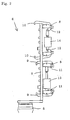
- a holding mechanism 6 for a coarse aluminum casting (W) is mounted on the arm 5 of the robot 3 so as to hold two of the coarse aluminum castings.
- Fig. 2 it comprises a supporting member 7 that is mounted on the end of the arm 5 and that extends in its longitudinal direction, and two pairs of claw-parts 9, 9, 10, 10 that are installed in two pairs of brackets 8, 8. They are rotatable around the supporting member 7.
- Two pairs of L-shaped links 11, 11, 12, 12 are rotatably jointed by pins at the ends of the claw-parts 9, 9, 10, 10 and pivoted at the crooks of the brackets 8, 8.
- Two cylinders 13, 14 are mounted between the ends of each pair of the links 11, 11, 12, 12 by pins.
- the two pairs of claw-parts 9, 9, 10, 10 can be opened and closed by the expansion and contraction of the cylinders 13, 14.
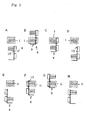
- a treated coarse aluminum casting (hereafter, treated work) that has been treated by the machining unit I is located on a setting table (i), and an untreated coarse aluminum casting (hereafter, untreated work) is held with the pair of claw-parts 10, 10 of the holding means 6.
- the holding means 6 that holds the untreated work moves and causes the vacant pair of claw-parts 9, 9 to be located on a setting table (i) so that it can grasp the treated work that has been treated by the machining unit I.
- the holding means 6 moves and removes the treated work that has been treated by the machining unit I from the setting table (i) as well as bringing the untreated work to the setting table (i), as shown in Fig. 3 - C .
- the holding means 6 opens the pair of claw-parts 10, 10 to put the untreated work on the setting table (i).
- the machining unit I processes the untreated work on the setting table (i).
- Fig. 3 - D the holding means 6 opens the pair of claw-parts 10, 10 to put the untreated work on the setting table (i).
- the machining unit I processes the untreated work on the setting table (i).
- the holding means 6 is rotated by 180 degrees around the axis of the arm 5 and causes the treated work that has been treated by the machining unit I to be reversed.
- the holding means 6 that holds the treated work that has been treated by the machining unit I also moves to a setting table (ii) of the machining unit II on which the treated work has been treated by the machining unit II.
- a holding means 6 that holds the treated work that has been treated by the machining unit I moves and positions the vacant pair of claw-parts 10, 10 on the setting table (ii) so as hold the treated work that has been treated by the machining unit II. Then, it grasps the treated work that has been treated by the machining unit II and that is located on the setting table (ii) by closing the pair of claw-parts 10, 10.
- the holding means 6 moves and removes the treated work that has been treated by the machining unit II from the setting table (ii) as well as brings the treated work that has been treated by the machining unit I to the setting table (ii). Then, as shown in Fig.
- the holding means 6 opens the pair of claw-parts 9, 9 to put the treated work that has been treated by the machining unit I on the setting table (ii). After that, the holding means 6 that holds the treated work that has been treated by the machining unit II moves to the predetermined position at a carrying-out corner. Then, the machining unit II processes the treated work that has been treated by the machining unit I and that is located on the setting table (ii).
Landscapes
- Engineering & Computer Science (AREA)
- Mechanical Engineering (AREA)
- Multi-Process Working Machines And Systems (AREA)
- Specific Conveyance Elements (AREA)
- Bending Of Plates, Rods, And Pipes (AREA)
- Manipulator (AREA)
- Manufacture And Refinement Of Metals (AREA)
Claims (6)
- Verfahren zum Ausführen der Nachbehandlung für Rohaluminium-Gussteile (W), die durch ein Inselfertigungssystem kontinuierlich hergestellt werden, wobei ein Roboter (3) mit einer Halteeinrichtung (6), die zwei Rohaluminium-Gussteile (W) halten kann, jedes der Rohaluminium-Gussteile (W) Stück für Stück zu der ersten und zweiten Bearbeitungseinheit (I, II) befördert, die an ihnen die Nachbehandlung ausführen, wobei das Verfahren die folgenden Schritte beinhaltet:Halten eines unbehandelten Rohaluminium-Gussteils (W), das an einer vorgegebenen Position eines abgewinkelten Einbringbereichs angeordnet ist, mit der Halteeinrichtung (6) und Befördern desselben neben die erste Bearbeitungseinheit (I) durch den Roboter (3),Halten eines behandelten Rohaluminium-Gussteils (W), das durch die erste Bearbeitungseinheit (I) behandelt worden ist, mit der Halteeinrichtung (6) und Überführen des unbehandelten Rohaluminium-Gussteils (W) von der Halteeinrichtung (6) zur ersten Bearbeitungseinheit (I),Befördern des behandelten Rohaluminium-Gussteils (W), das durch die erste Bearbeitungseinheit (I) behandelt worden ist, neben die zweite Bearbeitungseinheit (II) durch den Roboter (3),Halten eines behandelten Rohaluminium-Gussteils (W), das durch die zweite Bearbeitungseinheit (II) behandelt worden ist, mit der Halteeinrichtung (6) und Überführen des behandelten Rohaluminium-Gussteils (W), das durch die erste Bearbeitungseinheit (I) behandelt worden ist, von der Halteeinrichtung (6) zur zweiten Bearbeitungseinheit (II), undBefördern des behandelten Rohaluminium-Gussteils (W), das durch die zweite Bearbeitungseinheit (II) behandelt worden ist, zu einer vorgegebenen Position an einem abgewinkelten Ausbringbereich durch den Roboter (3).
- Verfahren zum Ausführen der Nachbehandlung der Rohaluminium-Gussteile (W) nach Anspruch 1, wobei:jedes behandelte Rohaluminium-Gussteil (W) um 180° gedreht wird während des Vorgangs, bei dem der Roboter (3) das behandelte Rohaluminium-Gussteil (W), das durch die erste Bearbeitungseinheit (I) behandelt worden ist, zur zweiten Bearbeitungseinheit (II) befördert.
- Anlage, welche die Nachbehandlungen für Rohaluminium-Gussteile (W) nach Anspruch 1 ausführt, mit
zwei Bearbeitungseinheiten (I, II), die in einem bestimmten Abstand voneinander installiert sind, und
einem Roboter (3), der in der Nähe der beiden Bearbeitungseinheiten (I, II) installiert ist und eine Halteeinrichtung (6) aufweist, die zwei Rohaluminium-Gussteile (W) gleichzeitig halten kann, dadurch gekennzeichnet, dass die Halteeinrichtung die beiden Rohaluminium-Gussteile (W) nebeneinander halten kann. - Anlage nach Anspruch 3, wobei
jede der beiden Bearbeitungseinheiten (I, II) ausgewählt wird aus oder eine beliebige Kombination ist aus einer Überlauf-Trenneinheit, die den Überlaufbereich der Rohaluminium-Gussteile (W) entfernt, einer Anguss-Schneideeinheit, die den Bereich nahe des Angusses des Rohaluminium-Gussteils (W) abträgt, einer Oberflächen-Vergütungseinheit, welche die Oberflächenvergütng des Rohaluminium-Gussteils (W) ausführt, einer Entgratungseinheit, welche die Grate des Rohaluminium-Gussteils (W) beseitigt, und einer Oberflächenbearbeitungseinheit, die das Oberflächenbearbeiten der Rohaluminium-Gussteile (W) ausführt. - Anlage nach Anspruch 3 oder 4, wobei
mehr als zwei der Bearbeitungseinheiten (I, II) in einer Einheit kombiniert sind. - Anlage nach Anspruch 3 bis 5, wobei
die Halteeinrichtung (6) das Rohaluminium-Gussteil (W) um 180° drehen kann.
Applications Claiming Priority (2)
| Application Number | Priority Date | Filing Date | Title |
|---|---|---|---|
| JP2004197098 | 2004-07-02 | ||
| PCT/JP2005/011972 WO2006003947A1 (ja) | 2004-07-02 | 2005-06-29 | アルミニウム鋳物粗材の後処理方法およびその設備 |
Publications (3)
| Publication Number | Publication Date |
|---|---|
| EP1767293A1 EP1767293A1 (de) | 2007-03-28 |
| EP1767293A4 EP1767293A4 (de) | 2007-10-31 |
| EP1767293B1 true EP1767293B1 (de) | 2013-08-14 |
Family
ID=35782754
Family Applications (1)
| Application Number | Title | Priority Date | Filing Date |
|---|---|---|---|
| EP05755826.4A Expired - Lifetime EP1767293B1 (de) | 2004-07-02 | 2005-06-29 | Verfahren und einrichtung zur nachbehandlung von aluminiumguss-grobmaterial |
Country Status (7)
| Country | Link |
|---|---|
| US (1) | US7975361B2 (de) |
| EP (1) | EP1767293B1 (de) |
| JP (1) | JP4036238B2 (de) |
| CN (1) | CN100528415C (de) |
| MX (1) | MX2007000271A (de) |
| TW (1) | TW200609060A (de) |
| WO (1) | WO2006003947A1 (de) |
Families Citing this family (2)
| Publication number | Priority date | Publication date | Assignee | Title |
|---|---|---|---|---|
| CN102690931A (zh) * | 2012-05-21 | 2012-09-26 | 温州瑞明工业股份有限公司 | 定位定点式空气淬火装置及其使用方法 |
| JP7259554B2 (ja) * | 2018-05-31 | 2023-04-18 | 新東工業株式会社 | 鋳造物及び鋳物の製造方法 |
Citations (3)
| Publication number | Priority date | Publication date | Assignee | Title |
|---|---|---|---|---|
| JPS59152038A (ja) * | 1983-01-28 | 1984-08-30 | Toshiba Corp | ワ−クの自動段取装置 |
| EP0139857A1 (de) * | 1983-07-11 | 1985-05-08 | Asea Ab | Roboteranlagen |
| GB2171047A (en) * | 1984-10-17 | 1986-08-20 | Takara Co Ltd | Automatically controlled rotational casting machine |
Family Cites Families (12)
| Publication number | Priority date | Publication date | Assignee | Title |
|---|---|---|---|---|
| US2792953A (en) * | 1953-12-08 | 1957-05-21 | King Donald Mayer | Mechanical handling mechanisms or devices |
| US3968885A (en) * | 1973-06-29 | 1976-07-13 | International Business Machines Corporation | Method and apparatus for handling workpieces |
| US4307891A (en) * | 1980-02-14 | 1981-12-29 | Robert Doornick | Remote control robot with person supporting platform |
| US5022636A (en) | 1990-03-26 | 1991-06-11 | Chick Machine Tool Inc. | Workholding apparatus |
| JP3052105B2 (ja) * | 1992-11-20 | 2000-06-12 | 東京エレクトロン株式会社 | 洗浄処理装置 |
| JP3300960B2 (ja) * | 1993-03-25 | 2002-07-08 | ヤマハ発動機株式会社 | 加振装置 |
| JP3148875B2 (ja) * | 1993-06-11 | 2001-03-26 | ヤマハ発動機株式会社 | 鋳造物用移送装置 |
| US5471738A (en) * | 1993-10-04 | 1995-12-05 | Ford Motor Company | Robotic system for inserting cylinder liners into internal combustion engine cylinder blocks |
| US5570920A (en) * | 1994-02-16 | 1996-11-05 | Northeastern University | Robot arm end effector |
| DE10020879B4 (de) * | 2000-04-28 | 2006-01-19 | Dipl.-Ing. Laempe Gmbh | Vorrichtung zum mechanischen Vor- und/oder Fertigbearbeiten von Gussteilen |
| US6632068B2 (en) * | 2000-09-27 | 2003-10-14 | Asm International N.V. | Wafer handling system |
| JP4079206B2 (ja) | 2000-12-15 | 2008-04-23 | 東京エレクトロン株式会社 | 基板検査装置および基板検査方法ならびに基板検査装置を備えた液処理装置 |
-
2005
- 2005-06-29 EP EP05755826.4A patent/EP1767293B1/de not_active Expired - Lifetime
- 2005-06-29 CN CNB2005800279907A patent/CN100528415C/zh not_active Expired - Lifetime
- 2005-06-29 TW TW094121847A patent/TW200609060A/zh unknown
- 2005-06-29 US US11/631,116 patent/US7975361B2/en active Active
- 2005-06-29 JP JP2006528757A patent/JP4036238B2/ja not_active Expired - Fee Related
- 2005-06-29 WO PCT/JP2005/011972 patent/WO2006003947A1/ja not_active Ceased
- 2005-06-29 MX MX2007000271A patent/MX2007000271A/es active IP Right Grant
Patent Citations (3)
| Publication number | Priority date | Publication date | Assignee | Title |
|---|---|---|---|---|
| JPS59152038A (ja) * | 1983-01-28 | 1984-08-30 | Toshiba Corp | ワ−クの自動段取装置 |
| EP0139857A1 (de) * | 1983-07-11 | 1985-05-08 | Asea Ab | Roboteranlagen |
| GB2171047A (en) * | 1984-10-17 | 1986-08-20 | Takara Co Ltd | Automatically controlled rotational casting machine |
Also Published As
| Publication number | Publication date |
|---|---|
| TW200609060A (en) | 2006-03-16 |
| JPWO2006003947A1 (ja) | 2008-04-17 |
| JP4036238B2 (ja) | 2008-01-23 |
| MX2007000271A (es) | 2007-04-02 |
| CN100528415C (zh) | 2009-08-19 |
| EP1767293A1 (de) | 2007-03-28 |
| EP1767293A4 (de) | 2007-10-31 |
| CN101005912A (zh) | 2007-07-25 |
| US7975361B2 (en) | 2011-07-12 |
| WO2006003947A1 (ja) | 2006-01-12 |
| US20090193954A1 (en) | 2009-08-06 |
Similar Documents
| Publication | Publication Date | Title |
|---|---|---|
| US4185376A (en) | Unmanned machining center with tool checking | |
| EP2070642B1 (de) | Verfahren und Vorrichtung zur Montage eines komplexen Produkts in einem Parallelprozesssystem | |
| JP6982003B2 (ja) | 鋳物工場用砂型を製造するための自動組立セルおよび組立ライン | |
| US5150624A (en) | Method of calibrating a rotary tool unit for an assembly line | |
| US20100233939A1 (en) | Method of and apparatus for grinding cams of a camshaft | |
| EP0788856B1 (de) | Verfahren und Vorrichtung zur Herstellung von Gussstücken aus Aluminiumlegierung | |
| RU2165836C2 (ru) | Универсальный автоматизированный комплекс для базирования крупногабаритных обводообразующих деталей, их механической обработки и сборки и способ базирования крупногабаритных обводообразующих деталей, их механической обработки и сборки | |
| US7785173B2 (en) | Superfinishing machine and method | |
| EP1767293B1 (de) | Verfahren und einrichtung zur nachbehandlung von aluminiumguss-grobmaterial | |
| RU99104053A (ru) | Универсальный автоматизированный комплекс для базирования крупногабаритных обводообразующих деталей, их механической обработки и сборки (кбмос) и способ его настройки | |
| JP2009142928A (ja) | 研削方法と研削装置 | |
| JP5512354B2 (ja) | 棒状ワークの加工方法及びその装置 | |
| US4266120A (en) | Unmanned machining center with tool checking | |
| CA2229824A1 (en) | An apparatus for working a workpiece | |
| JP2763354B2 (ja) | 歯切機用ワーク着脱装置 | |
| KR20010098913A (ko) | 긴 벨트형상 워크의 가공장치 및 가공방법 | |
| KR20070030944A (ko) | 알루미늄 주물 조재의 후처리 방법 및 그 설비 | |
| JP2609989B2 (ja) | ホーニング治具および自動ホーニングシステム | |
| JP2863224B2 (ja) | リングギヤ加工装置 | |
| EP1071537B1 (de) | Werkzeugmaschine und verfahren zur bearbeitung des verfahrens | |
| JPH07299628A (ja) | 自動翼面加工装置 | |
| US4727982A (en) | Workpiece transfer apparatus | |
| JP4815778B2 (ja) | 主軸ピックアップ旋盤 | |
| JPS63126619A (ja) | 曲げ加工機の自動化装置 | |
| JPH05123936A (ja) | 工作機械における被加工物の移送装置と移送方法 |
Legal Events
| Date | Code | Title | Description |
|---|---|---|---|
| PUAI | Public reference made under article 153(3) epc to a published international application that has entered the european phase |
Free format text: ORIGINAL CODE: 0009012 |
|
| 17P | Request for examination filed |
Effective date: 20061222 |
|
| AK | Designated contracting states |
Kind code of ref document: A1 Designated state(s): AT BE BG CH CY CZ DE DK EE ES FI FR GB GR HU IE IS IT LI LT LU MC NL PL PT RO SE SI SK TR |
|
| DAX | Request for extension of the european patent (deleted) | ||
| A4 | Supplementary search report drawn up and despatched |
Effective date: 20071001 |
|
| 17Q | First examination report despatched |
Effective date: 20091008 |
|
| GRAP | Despatch of communication of intention to grant a patent |
Free format text: ORIGINAL CODE: EPIDOSNIGR1 |
|
| GRAS | Grant fee paid |
Free format text: ORIGINAL CODE: EPIDOSNIGR3 |
|
| GRAA | (expected) grant |
Free format text: ORIGINAL CODE: 0009210 |
|
| AK | Designated contracting states |
Kind code of ref document: B1 Designated state(s): AT BE BG CH CY CZ DE DK EE ES FI FR GB GR HU IE IS IT LI LT LU MC NL PL PT RO SE SI SK TR |
|
| REG | Reference to a national code |
Ref country code: GB Ref legal event code: FG4D |
|
| REG | Reference to a national code |
Ref country code: CH Ref legal event code: EP Ref country code: AT Ref legal event code: REF Ref document number: 626491 Country of ref document: AT Kind code of ref document: T Effective date: 20130815 |
|
| REG | Reference to a national code |
Ref country code: IE Ref legal event code: FG4D |
|
| REG | Reference to a national code |
Ref country code: DE Ref legal event code: R096 Ref document number: 602005040874 Country of ref document: DE Effective date: 20131010 |
|
| REG | Reference to a national code |
Ref country code: NL Ref legal event code: VDEP Effective date: 20130814 Ref country code: AT Ref legal event code: MK05 Ref document number: 626491 Country of ref document: AT Kind code of ref document: T Effective date: 20130814 |
|
| REG | Reference to a national code |
Ref country code: LT Ref legal event code: MG4D |
|
| PG25 | Lapsed in a contracting state [announced via postgrant information from national office to epo] |
Ref country code: IS Free format text: LAPSE BECAUSE OF FAILURE TO SUBMIT A TRANSLATION OF THE DESCRIPTION OR TO PAY THE FEE WITHIN THE PRESCRIBED TIME-LIMIT Effective date: 20131214 Ref country code: PT Free format text: LAPSE BECAUSE OF FAILURE TO SUBMIT A TRANSLATION OF THE DESCRIPTION OR TO PAY THE FEE WITHIN THE PRESCRIBED TIME-LIMIT Effective date: 20131216 Ref country code: AT Free format text: LAPSE BECAUSE OF FAILURE TO SUBMIT A TRANSLATION OF THE DESCRIPTION OR TO PAY THE FEE WITHIN THE PRESCRIBED TIME-LIMIT Effective date: 20130814 Ref country code: CY Free format text: LAPSE BECAUSE OF FAILURE TO SUBMIT A TRANSLATION OF THE DESCRIPTION OR TO PAY THE FEE WITHIN THE PRESCRIBED TIME-LIMIT Effective date: 20130717 Ref country code: LT Free format text: LAPSE BECAUSE OF FAILURE TO SUBMIT A TRANSLATION OF THE DESCRIPTION OR TO PAY THE FEE WITHIN THE PRESCRIBED TIME-LIMIT Effective date: 20130814 Ref country code: SE Free format text: LAPSE BECAUSE OF FAILURE TO SUBMIT A TRANSLATION OF THE DESCRIPTION OR TO PAY THE FEE WITHIN THE PRESCRIBED TIME-LIMIT Effective date: 20130814 |
|
| PG25 | Lapsed in a contracting state [announced via postgrant information from national office to epo] |
Ref country code: GR Free format text: LAPSE BECAUSE OF FAILURE TO SUBMIT A TRANSLATION OF THE DESCRIPTION OR TO PAY THE FEE WITHIN THE PRESCRIBED TIME-LIMIT Effective date: 20131115 Ref country code: SI Free format text: LAPSE BECAUSE OF FAILURE TO SUBMIT A TRANSLATION OF THE DESCRIPTION OR TO PAY THE FEE WITHIN THE PRESCRIBED TIME-LIMIT Effective date: 20130814 Ref country code: BE Free format text: LAPSE BECAUSE OF FAILURE TO SUBMIT A TRANSLATION OF THE DESCRIPTION OR TO PAY THE FEE WITHIN THE PRESCRIBED TIME-LIMIT Effective date: 20130814 Ref country code: FI Free format text: LAPSE BECAUSE OF FAILURE TO SUBMIT A TRANSLATION OF THE DESCRIPTION OR TO PAY THE FEE WITHIN THE PRESCRIBED TIME-LIMIT Effective date: 20130814 Ref country code: PL Free format text: LAPSE BECAUSE OF FAILURE TO SUBMIT A TRANSLATION OF THE DESCRIPTION OR TO PAY THE FEE WITHIN THE PRESCRIBED TIME-LIMIT Effective date: 20130814 |
|
| PG25 | Lapsed in a contracting state [announced via postgrant information from national office to epo] |
Ref country code: CY Free format text: LAPSE BECAUSE OF FAILURE TO SUBMIT A TRANSLATION OF THE DESCRIPTION OR TO PAY THE FEE WITHIN THE PRESCRIBED TIME-LIMIT Effective date: 20130814 |
|
| PG25 | Lapsed in a contracting state [announced via postgrant information from national office to epo] |
Ref country code: DK Free format text: LAPSE BECAUSE OF FAILURE TO SUBMIT A TRANSLATION OF THE DESCRIPTION OR TO PAY THE FEE WITHIN THE PRESCRIBED TIME-LIMIT Effective date: 20130814 Ref country code: SK Free format text: LAPSE BECAUSE OF FAILURE TO SUBMIT A TRANSLATION OF THE DESCRIPTION OR TO PAY THE FEE WITHIN THE PRESCRIBED TIME-LIMIT Effective date: 20130814 Ref country code: EE Free format text: LAPSE BECAUSE OF FAILURE TO SUBMIT A TRANSLATION OF THE DESCRIPTION OR TO PAY THE FEE WITHIN THE PRESCRIBED TIME-LIMIT Effective date: 20130814 Ref country code: NL Free format text: LAPSE BECAUSE OF FAILURE TO SUBMIT A TRANSLATION OF THE DESCRIPTION OR TO PAY THE FEE WITHIN THE PRESCRIBED TIME-LIMIT Effective date: 20130814 Ref country code: RO Free format text: LAPSE BECAUSE OF FAILURE TO SUBMIT A TRANSLATION OF THE DESCRIPTION OR TO PAY THE FEE WITHIN THE PRESCRIBED TIME-LIMIT Effective date: 20130814 Ref country code: CZ Free format text: LAPSE BECAUSE OF FAILURE TO SUBMIT A TRANSLATION OF THE DESCRIPTION OR TO PAY THE FEE WITHIN THE PRESCRIBED TIME-LIMIT Effective date: 20130814 |
|
| PG25 | Lapsed in a contracting state [announced via postgrant information from national office to epo] |
Ref country code: ES Free format text: LAPSE BECAUSE OF FAILURE TO SUBMIT A TRANSLATION OF THE DESCRIPTION OR TO PAY THE FEE WITHIN THE PRESCRIBED TIME-LIMIT Effective date: 20130814 Ref country code: IT Free format text: LAPSE BECAUSE OF FAILURE TO SUBMIT A TRANSLATION OF THE DESCRIPTION OR TO PAY THE FEE WITHIN THE PRESCRIBED TIME-LIMIT Effective date: 20130814 |
|
| PLBE | No opposition filed within time limit |
Free format text: ORIGINAL CODE: 0009261 |
|
| STAA | Information on the status of an ep patent application or granted ep patent |
Free format text: STATUS: NO OPPOSITION FILED WITHIN TIME LIMIT |
|
| 26N | No opposition filed |
Effective date: 20140515 |
|
| REG | Reference to a national code |
Ref country code: DE Ref legal event code: R097 Ref document number: 602005040874 Country of ref document: DE Effective date: 20140515 |
|
| PG25 | Lapsed in a contracting state [announced via postgrant information from national office to epo] |
Ref country code: MC Free format text: LAPSE BECAUSE OF FAILURE TO SUBMIT A TRANSLATION OF THE DESCRIPTION OR TO PAY THE FEE WITHIN THE PRESCRIBED TIME-LIMIT Effective date: 20130814 Ref country code: LU Free format text: LAPSE BECAUSE OF FAILURE TO SUBMIT A TRANSLATION OF THE DESCRIPTION OR TO PAY THE FEE WITHIN THE PRESCRIBED TIME-LIMIT Effective date: 20140629 |
|
| REG | Reference to a national code |
Ref country code: CH Ref legal event code: PL |
|
| REG | Reference to a national code |
Ref country code: IE Ref legal event code: MM4A |
|
| REG | Reference to a national code |
Ref country code: FR Ref legal event code: ST Effective date: 20150227 |
|
| PG25 | Lapsed in a contracting state [announced via postgrant information from national office to epo] |
Ref country code: LI Free format text: LAPSE BECAUSE OF NON-PAYMENT OF DUE FEES Effective date: 20140630 Ref country code: IE Free format text: LAPSE BECAUSE OF NON-PAYMENT OF DUE FEES Effective date: 20140629 Ref country code: CH Free format text: LAPSE BECAUSE OF NON-PAYMENT OF DUE FEES Effective date: 20140630 |
|
| PG25 | Lapsed in a contracting state [announced via postgrant information from national office to epo] |
Ref country code: FR Free format text: LAPSE BECAUSE OF NON-PAYMENT OF DUE FEES Effective date: 20140630 |
|
| PG25 | Lapsed in a contracting state [announced via postgrant information from national office to epo] |
Ref country code: BG Free format text: LAPSE BECAUSE OF FAILURE TO SUBMIT A TRANSLATION OF THE DESCRIPTION OR TO PAY THE FEE WITHIN THE PRESCRIBED TIME-LIMIT Effective date: 20130814 |
|
| PG25 | Lapsed in a contracting state [announced via postgrant information from national office to epo] |
Ref country code: HU Free format text: LAPSE BECAUSE OF FAILURE TO SUBMIT A TRANSLATION OF THE DESCRIPTION OR TO PAY THE FEE WITHIN THE PRESCRIBED TIME-LIMIT; INVALID AB INITIO Effective date: 20050629 Ref country code: TR Free format text: LAPSE BECAUSE OF FAILURE TO SUBMIT A TRANSLATION OF THE DESCRIPTION OR TO PAY THE FEE WITHIN THE PRESCRIBED TIME-LIMIT Effective date: 20130814 |
|
| PGFP | Annual fee paid to national office [announced via postgrant information from national office to epo] |
Ref country code: GB Payment date: 20200625 Year of fee payment: 16 |
|
| GBPC | Gb: european patent ceased through non-payment of renewal fee |
Effective date: 20210629 |
|
| PG25 | Lapsed in a contracting state [announced via postgrant information from national office to epo] |
Ref country code: GB Free format text: LAPSE BECAUSE OF NON-PAYMENT OF DUE FEES Effective date: 20210629 |
|
| PGFP | Annual fee paid to national office [announced via postgrant information from national office to epo] |
Ref country code: DE Payment date: 20240619 Year of fee payment: 20 |
|
| REG | Reference to a national code |
Ref country code: DE Ref legal event code: R071 Ref document number: 602005040874 Country of ref document: DE |