EP1764431B1 - Yarn feeding device for weft knitting machine - Google Patents
Yarn feeding device for weft knitting machine Download PDFInfo
- Publication number
- EP1764431B1 EP1764431B1 EP05751161.0A EP05751161A EP1764431B1 EP 1764431 B1 EP1764431 B1 EP 1764431B1 EP 05751161 A EP05751161 A EP 05751161A EP 1764431 B1 EP1764431 B1 EP 1764431B1
- Authority
- EP
- European Patent Office
- Prior art keywords
- yarn feeding
- yarn
- feeding port
- feeder
- feeder rod
- Prior art date
- Legal status (The legal status is an assumption and is not a legal conclusion. Google has not performed a legal analysis and makes no representation as to the accuracy of the status listed.)
- Expired - Lifetime
Links
Images


Classifications
-
- D—TEXTILES; PAPER
- D04—BRAIDING; LACE-MAKING; KNITTING; TRIMMINGS; NON-WOVEN FABRICS
- D04B—KNITTING
- D04B15/00—Details of, or auxiliary devices incorporated in, weft knitting machines, restricted to machines of this kind
- D04B15/38—Devices for supplying, feeding, or guiding threads to needles
- D04B15/54—Thread guides
- D04B15/56—Thread guides for flat-bed knitting machines
-
- D—TEXTILES; PAPER
- D04—BRAIDING; LACE-MAKING; KNITTING; TRIMMINGS; NON-WOVEN FABRICS
- D04B—KNITTING
- D04B15/00—Details of, or auxiliary devices incorporated in, weft knitting machines, restricted to machines of this kind
- D04B15/38—Devices for supplying, feeding, or guiding threads to needles
- D04B15/54—Thread guides
-
- D—TEXTILES; PAPER
- D04—BRAIDING; LACE-MAKING; KNITTING; TRIMMINGS; NON-WOVEN FABRICS
- D04B—KNITTING
- D04B7/00—Flat-bed knitting machines with independently-movable needles
- D04B7/24—Flat-bed knitting machines with independently-movable needles for producing patterned fabrics
- D04B7/26—Flat-bed knitting machines with independently-movable needles for producing patterned fabrics with colour patterns
Definitions
- the present invention relates to a yarn feeding device for a weft knitting machine comprising a plurality of yarn feeders, in which a yarn feeding port of the yarn feeder put on standby at an end portion of the knitting fabric or at a changed portion of the knitting pattern, for example, an intarsia knitting pattern, can be switched over to a position outside the fabric knitting region.
- a yarn feeder associated with a carriage to feed yarn to a needle in a needle bed for the knitting fabric is kept on a standby position outside the fabric knitting region.
- the position of a yarn is lowered proportionately as the yarn feeder greatly moves beyond the boundary with the adjoining knitting area so that the yarn feeding condition can be improved.
- the amount of swing of the yarn feeder must be sufficiently increased correspondingly to the amount necessitated to retire a yarn extending between the yarn feeder that has stopped inside the adjoining knitting region and the knitted fabric to a position that does not cause any obstruction of the subsequent knitting operation in the next knitting region.
- a yarn feeder of a weft knitting machine comprising a switching mechanism for switch-swinging the position of the yarn feeding port installed in a feeder case, the switching mechanism further comprising a pressing operation part switch-operating the swinging direction and altitude of the yarn feeding port in association, wherein the said yarn feeder is capable of obtaining the same effect as in a case in which the amount of swinging of a yarn feeder is substantially increased without increasing the amount thereof (See Patent Document 1).
- Patent Document 1 International Publication WO02-079556
- Prior art document EP 1 418 263 A1 which is a document of the applicant of the present application, discloses a switching mechanism for switching the position of a yarn feeding mouth to another and swinging a yarn feeder.
- the switching mechanism includes a push operating portion for changing a swing direction of the yarn feeding mouth and a height position thereof in cooperation with a leading means until a yarn feeder selected by the leading means feeds a yarn and is led from a stopped state.
- the push operating portion forms a lowering surface in a surface of the push operating portion. The lowering surface is used to further lower the yarn feeding mouth from a yarn feeding position so as to allow the yarn to pass under a backface side of the needle.
- the yarn feeding port of the yarn feeder moves vertically interlocking with a yarn feeding rod operated by a entraining device so that the yarn feeding port will be largely swung to the left or the right on its standby position and stop in a high position thereafter, and, as a result, the yarn drawn from the stitch at the end of the knitting region being pulled up. Therefore, there was such a problem that it may occur clogging of the stitch at the end of the knitting region and become very hard to form a uniform stitch therein.
- the present invention has been proposed in consideration of the aforementioned problems. It is therefore an object of the present invention to provide a yarn feeder of a yarn feeding device used for a weft knitting machine, which is capable of producing a fabric having uniform stitches without the yarn free-lifting from the yarn feeder.
- a yarn feeding device for weft knitting machine comprising a plurality of yarn feeders, the yarn feeding device having the features as set forth in claim 1.
- Preferred embodiments of the yarn feeding device are stated in the subclaims 2 - 4.
- a yarn feeding device used for a weft knitting machine comprising a plurality of yarn feeders which are engaged with and can slide on knitting yarn guide rails arranged over a needle bed, an entraining means for entraining selectively any one of the yarn feeders and a switching mechanism for changing over the swing of a yarn feeding port provided at a lower end of a feeder rod between a yarn feeding position and a standby position interlocking with the operation of the entraining means, wherein before a selected yarn feeder through the operation of the entraining means has been entrained from a standby position to a yarn feeding position, the switching mechanism is operaable so as to swing the yarn feeding port from the standby position to the yarn feeding position while, after having completed yarn feeding operation, the yarn feeding port is swung from one yarn feeding position to another standby position interlocking with the released selective operation of the entraining means, wherein:
- a yarn feeding device used for a weft knitting machine is characterized in that a lower plate that forms the feeder rod comprises a yarn feeding port forming member, a spring storage member disposed between the upper portion of the yarn feeding port forming member and a feeder rod guide, a compression spring that forms a depression member stored in the spring storage member, and a receiving portion that receives a lower end of the compression spring, wherein an abutment portion for abutting against a regulation unit is provided on an upper end of the spring storage members so as to move up and force the yarn feeding port forming member upward with the compression spring.
- a yarn feeding device used for a weft knitting machine is characterized in that a slot is provided with at least either one of an upper end of the yarn feeding port forming member and a lower end of the spring storage member, through which a fixing element is inserted to be coupled to each other such that a height position of the yarn feeding port is adjustable by changing of coupling position.
- a yarn feeder of a yarn feeding device used for a weft knitting machine is characterized in that a variable uppermost regulation position of the yarn feeding port can be adjusted by replacing the spring storage member having a different distance between a portion coupled to the yarn feeding port forming member and an upper portion abutting against the upper end of the spring storage member.
- the feeder rod is formed of at least two members, one being an upper member activated by the entraining means and another one being a lower member composed of a yarn feeding port at its lower end, both of the members being arranged to be relatively slide each other in a vertical direction and provided with a push-up member forced upward respectively, and the upper member of the feeder rod is moved downward through the action of the entraining means, as well as the lower member of the feeder rod downward so that the yarn feeding port is set into the yarn feeding position, while the feeder rod is moved upward into the standby position by means of a regulation unit provided on a support member bearing the feeder rod so as to keep the lower member from rising against the action of a force caused by the push-up member, and the rise of the lower member of the feeder rod is resultantly made less than that of the upper member to limit the rise of the yarn feeding port in the standby position below the determined altitude. Therefore, the present invention resides not only in reliably obtaining the swing width of the yarn feeder but also in preventing from a larger altitude
- the yarn feeder does not have greatly slid out of the knitting region, thus improving the productivity by reducing the sliding distance of the yarn feeder.
- the yarn feeding port in the present invention can be placed at a lower altitude. Therefore, even in case of a weft knitting machine of rough gauge or a needle-jumping-over knitting operation in which a large extent of swing of the yarn feeder is required, it can be advantageously kept at an ideal height apart from the yarn feeding port.
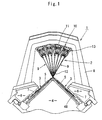
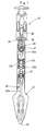
- Fig. 1 is a lateral view of a weft knitting machine having a yarn feeding device including yarn feeders of the present invention, wherein a reference numeral 1 denotes the weft knitting machine in its entirety, and 2 denotes the yarn feeding device.
- the weft knitting machine 1 has a pair of front and rear needle beds 3 disposed on a frame 4 in a fan shape with extreme ends thereof confronting each other, and each needle bed 3 has a plurality of knitting needles 5 thereon in parallel with each other so that they are movable back and force.
- a carriage 6 is disposed on an upper surface of each needle bed 3 so that it can be caused to reciprocate by a belt drive device (not shown).
- a bat 48 of each knitting needle 5 is operated by a knitting cam 7 attached to the carriage 6 as shown in the drawing so as to be advanced and retracted.
- a gate arm (slide drive mechanism) 8 is mounted on the carriages 6 so as to stride over the front and back needle beds 3, and is integrally coupled with the carriages 6.
- Mounted on the gate arm 8 are an entraining device 10 that brings yarn feeders 9, and a push-down member 13 that pushes down yarn feeding ports 12 of the respective yarn feeder 9 to positions adjacent to each extreme end of the knitting needles 5 and 5.
- Four knitting yarn guide rails 11 are elongated longitudinally over the needle beds 3 and arranged backward and forward over there in the form of a fan at the position in the radical direction apart from the center nearly close to the extreme one end of the knitting needles 5 disposed in parallel with each other on the needle beds 3.
- the entraining device 10 includes transmission rods 15 for transmitting movement of output shafts of solenoids, which are projected and retracted in response to a signal output from a controller (not shown) to entraining pins 14 as shown in Fig. 2 .
- the entraining pins 14 are forced downward by means of springs 16 engaged into engagement portions 19 which are formed respectively on a pair of right and left swinging pieces 18 disposed on a feeder case 17 of the respective yarn feeder 9 at portions adjacent to the center of upper end thereof. In this way, the yarn feeders 9 are fed by the entraining pins 14 (see Fig. 3 ).
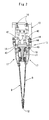
- the yarn feeder 9 is composed of a feeder case 17 supported by the knitting yarn guide rail 11 to be able to slide thereon a feeder rod 20 provided with the yarn feeding port 12 at its lower end and suspended from the lower end portion of the feeder case 17, and a neutral position holding mechanism that hangs a feeder rod guide 21 for guiding the feeder rod 20 and holds the yarn feeding ports 12 in a neutral state at the standby position.
- An upper pivot portion of the feeder rod guide 21 is pivoted to the feeder case 17 to be able to swing horizontally.
- the feeder rod 20 is formed of a slender sheet-shaped lower plate 22 whose right and left side edge portions are supported by the feeder rod guide 21 to be able to slide upward and downward, an intermediate plate 23 whose lower end portion is moveably coupled with an upper end portion of the lower plate 22, and an upper plate 25 whose lower end portion is coupled with the intermediate plate 23 through a push-down roller 24 projecting from an upper back surface of the intermediate plate 23.
- the push-down roller 24 is engaged with a lateral slot 26 formed at a lower end portion of the upper plate 25.
- An upper member of the yarn feeder 9 is composed of the upper plate 25 and the intermediate plate 23.
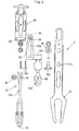
- the lower plate 22 comprises a lower member which is composed of a yarn feeding port forming member 22a and a spring storage member 22b interposed in a portion above the yarn feeding port forming member 22a between the yarn feeding port forming member 22a and the feeder rod guide 21, compression springs 22c stored in the spring storage member 22b and a receiving member 22d for supporting the compressed springs 22c (urging portion), the receiving member 22d being engaged with an engagement hole 21a of the feeder rod guide 21.
- the spring storage member 22b is provided at the upper portion thereof with an abutment portion 22e abutting against a regulation portion 46 (described later) such that the lower plate 22 is forced upward by the compressed springs 22c.
- the regulation portion 46 that abuts against the abutment portion 22e is formed of a dice-like member 47 fixed to be tightened to the feeder case 17 together with the feeder rod guide 21 through a sliding slot 23a.
- coil springs 27 are mounted on the coil receiving portions 28 of the feeder case 17 with the middle plate 23 and the lower plate 22 so as to forcibly move the upper plate 25 vertically (see fig.7 ).
- a switching roller 30 of a switching mechanism 29 for switching a position of the yarn feeding port 12 projects from a front surface of the intermediate plate 23 at an upper end portion thereof.
- the switching mechanism 29 includes the switching roller 30, a regulation hole 31 formed through the feeder case 17 for regulating a swinging motion of the switching roller 30, and a selection lever 32 disposed on a back surface side of the regulation hole 31.
- the regulation hole 31 is formed in substantially a trifoliate shape having spaces with which the switching roller 30 is engaged at the center, upper left and upper right portions thereof.
- the selection lever 32 that sets an upward moving direction of the switching roller 30 confronting the regulation hole 31 is formed in substantially a T-shape with its upper end portion 32a formed in a gentle V-shape.
- the selection lever 32 is pivoted to the feeder case 17 at a pivot portion 32b at the center, which hangs down from a center of the upper end portion 32a and terminates in an arrow shape having oblique surfaces 34 and 34 on the right and left sides thereof for directing the upward moving direction of the switching roller 30.
- the intermediate portion between the oblique surfaces 34 and 34 has a roller receiving portion 35 that receives the switching roller 30 in a neutral position.
- a holding means 36 for holding the switched positions of the selection lever 32 is disposed at an upper portion of an arrow-shaped portion formed of the two oblique surfaces 34 and 34 and the neutral position holding means.
- the holding means 36 is arranged such that mustache-like elastic portions 37 are extended in both horizontal directions from an upper portion of the arrow-like portion, and gripping portions 38 and 39 are formed by bending portions near extreme ends of the elastic portions 37. Further engaging projections 40 are formed on a back surface of the feeder case 17 such that any one of them is engaged with any one of the gripping portions 38 and 39 when the selection lever 32 is turned to any one of the right or left position or the neutral position.
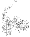
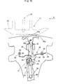
- the neutral position holding mechanism 50 that holds the yarn feeding port 12 at the low neutral position adjacent to the knitting needle 5 while keeping the selection lever 32 in an upright state at the standby position is, as shown in Fig. 4 , composed of pivot portions 51 and 51 each formed through the upper end portion of the feeder case 17 and a pair of links 53 having rotating portions 52 and 52 pivoted to the pivot portions 51 and 51 so as to be enabled to swing.
- the pair of links 53 includes engagement portions 54 each having the extreme end portion engaged with each other at the center of the feeder case 17 in a horizontal direction.
- Protrusions 55 for operating the selection lever 32 into the neutral position by pushing up the upper end portion 32a of the selection lever 32 from the lower side are formed at the respective side surfaces that face with each other.
- Operation pieces 56 each extending to the left and the right from the rotating portions 52 are formed at the upper portion of the respective links 53.
- the operation pieces 56 swung by the entraining pins 14 are formed to extend to the left and the right from the rotating portions 52, and have the upper surface oblique to be lower as it becomes closer to the engagement portion 54, and the outer end oblique downward.
- a reference numeral 57 denotes a plate of preventing dropout of the link 53.
- the push-down member 13 that pushes down the feeder rod 20 is composed of a coupling plate 42 having one end coupled with the entraining pin 14 at an intermediate height position thereof, and a cam plate 43 having upper end portion coupled with another end of the coupling plate 42, whereby the cam plate 43 can be swung back and forth about a swing pivot pin 44 interlocking with up and down movement of the entraining pin 14(see Fig.2 ).
- the entraining pin 14 is disposed on the middle of the cam plate 43 aside of the knitting yarn guide rail 11.
- a reference numeral 46 shown in Fig. 4 denotes a brake unit formed of a magnet attracted to the knitting yarn guide rail. Since the yarn feeder 9 is reduced in size and weight, the yarn feeder 9 can be stopped at an accurate position even by a light sliding friction generated by an attracting force of the magnet.
- the present invention never causes the problem of unstable on stop position due to a large inertia force applied thereon, even if the yarn feeder interlocking with entraining device is stopped in a place, which fails to allow the yarn feeder to stop at the desired position. It is unnecessary to provide a special brake unit for stopping the yarn feeder at the desired position against the large inertia force.
- the knitting needles 5 disposed in parallel with each other on the needle beds 3 are advanced and retreated by the knitting cams 7.
- a solenoid When the carriages 6 travel, in a portion where no knitting is executed, a solenoid is actuated responding to an output signal of pattern knitting operation so that the output shaft of the solenoid is projected downward and the entraining pin 14 of the entraining device 10 is moved upward against tension of a spring 16 through the transmission rod 15 thereafter.
- the solenoid is actuated in response to the signal output from the controller in front of a position where the carriage 6 confronts a predetermined yarn feeder 9 for supplying yarn to the knitting needles 5, and when the output shaft of the solenoid is receded upward, the entraining pin 14 moved upward is pushed downward by the tension of the spring 16.
- the cam plate 43 of the push-down member 13 is swung toward the yarn feeder 9 about the swing pivot pin 44 through the coupling plate 42 (refer to the cam plate 43 at the left side of Fig. 2 ).
- the cam plate 43 pushes down the upper end portion (push-down portion) 25a of the upper plate 25 against a force caused by contraction of a coil spring 27, the switching roller 30 borne in the regulation hole 31 being guided downward to be centered in the lower portion of the regulation hole 31 and put on the descended position as shown in Fig. 9 .
- the feeder rod guide 21 stands upright at the center of the feeder case 17 while projecting the yarn feeding port 12 of the feeder rod 20 downward from the lower end of the feeder rod guide 21, and the yarn feeding port 12 is located at a yarn feed position adjacent to the knitting needles 5 on a needle bed 3.
- the selection lever 32 is swung counterclockwise about the turning center position of the pivot portion 32b from one status as shown in Fig. 9 to the other status as shown in Fig. 10 .
- the position of the selection lever 32 is held because the left gripping portion 38, which forms a holding means 36, of the elastic portion 37 of the selection lever 32 is disengaged from the engaging projection 40, and because the right gripping portion 39 is engaged with engaging projection 41.
- the yarn feeder 9 is brought by the carriage 6, and yarn is fed to the knitting needles 5 from the yarn feeding port 12 of the yarn feeder 9. In this manner, the knitting operation is performed with the yarn fed from the yarn feeder 9 in the right knitting region.
- the solenoid When knitting operation of the determined knitting region having been finished and reached to the standby position outside the knitting region, the solenoid is energized in response to a signal output from the controller, in which the output shaft of the solenoid projects downward, the entraining pin 14 expanded downward being pushed up against the force caused by stretch of the spring 16.
- the lower portion of the selection lever 32 resides in a position diagonally deflected on the right side as shown in Fig.10 so that the switching roller 30 on its upper end is guided by the left side oblique surface 34 of the selection lever 32, and, therefore, the yarn feeding rod 12 ascends while it turning anticlockwise.
- the yarn feeding port forming member 22a stops rising vertically opposed to a force caused by the compression spring 22c without exceeding the current latitude while only the intermediate plate 23 keeps ascending furthermore in response to a push-up force caused by the compression spring 27. Resultantly, the yarn feeding port 12 starts to swing on the right side with stopping its further ascending.
- the yarn feeding port of the yarn feeder of the present invention can be held at a lower altitude, upon changing a yarn feeder at a knitting boundary portion of a knitted fabric, for example, an intarsia knitted fabric, the yarn feeder is very far away from the boundary portion. In this way, it can make a yarn feeding machine to perform such an intarsia knitting operation without causing interference between the yarn feeders each other.
- the reference numeral 61 denotes a swing regulation unit, in which after having depressed the upper plate 25 in the position that is not influenced by the cam plate 43, that is, in the yarn feeding position, the protrusion 61a of the swing regulation unit 61 is inserted into the lower end of the slide slot 23a formed through the intermediate plate 23 and the swing regulation unit 61 is mounted by screwing the fixture 62 against the female screw 63 in the feeder case 17, and, as a result, the yarn feeding rod guide 21 can be constrained on its sides to regulate the swinging motion to be operated as a yarn feeder for the normal knitting.
Landscapes
- Engineering & Computer Science (AREA)
- Textile Engineering (AREA)
- Knitting Machines (AREA)
Applications Claiming Priority (2)
| Application Number | Priority Date | Filing Date | Title |
|---|---|---|---|
| JP2004200779A JP4125267B2 (ja) | 2004-07-07 | 2004-07-07 | 横編機における給糸装置のヤーンフィーダ |
| PCT/JP2005/010851 WO2006006335A1 (ja) | 2004-07-07 | 2005-06-14 | 横編機における給糸装置のヤーンフィーダ |
Publications (3)
| Publication Number | Publication Date |
|---|---|
| EP1764431A1 EP1764431A1 (en) | 2007-03-21 |
| EP1764431A4 EP1764431A4 (en) | 2009-12-02 |
| EP1764431B1 true EP1764431B1 (en) | 2014-12-24 |
Family
ID=35783690
Family Applications (1)
| Application Number | Title | Priority Date | Filing Date |
|---|---|---|---|
| EP05751161.0A Expired - Lifetime EP1764431B1 (en) | 2004-07-07 | 2005-06-14 | Yarn feeding device for weft knitting machine |
Country Status (6)
| Country | Link |
|---|---|
| US (1) | US7543462B2 (enExample) |
| EP (1) | EP1764431B1 (enExample) |
| JP (1) | JP4125267B2 (enExample) |
| KR (1) | KR101094734B1 (enExample) |
| CN (1) | CN100535218C (enExample) |
| WO (1) | WO2006006335A1 (enExample) |
Families Citing this family (18)
| Publication number | Priority date | Publication date | Assignee | Title |
|---|---|---|---|---|
| DE102010010892B4 (de) * | 2010-03-10 | 2013-08-01 | H. Stoll Gmbh & Co. Kg | Verfahren zur Herstellung eines Gestricks und Flachstrickmaschine |
| US9060570B2 (en) | 2011-03-15 | 2015-06-23 | Nike, Inc. | Method of manufacturing a knitted component |
| US8522577B2 (en) * | 2011-03-15 | 2013-09-03 | Nike, Inc. | Combination feeder for a knitting machine |
| US8839532B2 (en) | 2011-03-15 | 2014-09-23 | Nike, Inc. | Article of footwear incorporating a knitted component |
| US10172422B2 (en) | 2011-03-15 | 2019-01-08 | Nike, Inc. | Knitted footwear component with an inlaid ankle strand |
| US8387418B1 (en) * | 2011-09-19 | 2013-03-05 | Pai Lung Machinery Mill Co., Ltd. | Yarn feeder for flat knitting machines |
| KR101226417B1 (ko) * | 2011-09-21 | 2013-01-24 | 파이룽 머시너리 밀 코., 엘티디. | 횡편기용 실 공급기 |
| US9371603B2 (en) * | 2013-02-28 | 2016-06-21 | Nike, Inc. | Feeder for knitting machine with friction reducing features |
| CN103741359B (zh) * | 2013-12-19 | 2015-05-27 | 瑞安市威克横机配件有限公司 | 组合交织导纱器 |
| JP6257322B2 (ja) * | 2013-12-27 | 2018-01-10 | 株式会社島精機製作所 | 横編機の給糸装置 |
| CN106906564B (zh) * | 2017-04-25 | 2018-12-14 | 绍兴金楚印染有限公司 | 一种防止导纱过程中动力中断的设备 |
| CN107829205B (zh) * | 2017-12-14 | 2023-07-04 | 唐山雾谷机电设备有限公司 | 换线器的喂纱结构 |
| JP7054913B2 (ja) * | 2018-04-19 | 2022-04-15 | 常陽工学株式会社 | 積層体製造装置とこの装置を用いた積層体の製造方法 |
| CN111501184B (zh) * | 2019-01-30 | 2021-10-26 | 佰龙机械厂股份有限公司 | 具有变化喂纱位置的横编机喂纱器 |
| US11421354B2 (en) * | 2019-02-27 | 2022-08-23 | Pai Lung Machinery Mill Co., Ltd. | Flat knitting machine yarn feeder with variable yarn feeding positions |
| TWD208383S (zh) * | 2019-06-18 | 2020-11-21 | 義大利商聖東尼股份公司 | 紡織機構件 |
| TWD208197S (zh) * | 2019-06-18 | 2020-11-11 | 義大利商聖東尼股份公司 | 紡織機構件 |
| JP2024158391A (ja) * | 2023-04-27 | 2024-11-08 | 株式会社島精機製作所 | 横編機 |
Family Cites Families (12)
| Publication number | Priority date | Publication date | Assignee | Title |
|---|---|---|---|---|
| DE3716931C1 (de) * | 1986-07-01 | 1988-01-28 | Stoll & Co H | Fadenfuehrerschlitten |
| JP2807848B2 (ja) * | 1991-07-11 | 1998-10-08 | 株式会社島精機製作所 | 横編機におけるヤーンフィーダの駆動装置 |
| EP0572360B1 (en) * | 1992-05-25 | 1998-09-23 | Emm S.R.L. | Yan carrier moving device for a flat knitting machine |
| JP3498270B2 (ja) * | 1994-04-28 | 2004-02-16 | 株式会社島精機製作所 | 横編機における糸案内方法及び装置 |
| JP3044370B2 (ja) * | 1997-08-21 | 2000-05-22 | 株式会社島精機製作所 | 横編機における糸供給装置 |
| US6647749B2 (en) * | 2000-02-29 | 2003-11-18 | Shima Seiki Mfg., Ltd. | Yarn feeding device of flat knitting machine |
| KR100867140B1 (ko) * | 2001-03-29 | 2008-11-06 | 가부시키가이샤 시마세이키 세이사쿠쇼 | 횡편기의 얀 피더 |
| CN100519866C (zh) * | 2001-07-24 | 2009-07-29 | 株式会社岛精机制作所 | 横机的喂纱装置及横机的喂纱方法 |
| EP1602762B1 (en) * | 2003-02-26 | 2013-04-10 | Shima Seiki Manufacturing Limited | Weft knitting machine with a yarn carrier |
| EP1605086B1 (en) * | 2003-03-07 | 2008-09-24 | Shima Seiki Mfg., Ltd | Yarn feeder of weft knitting machine |
| JP4125212B2 (ja) * | 2003-10-10 | 2008-07-30 | 株式会社島精機製作所 | 着脱式編成用移動体および編成部材切換装置を備える横編機 |
| JP4125268B2 (ja) * | 2004-07-07 | 2008-07-30 | 株式会社島精機製作所 | 横編機における給糸装置のヤーンフィーダ |
-
2004
- 2004-07-07 JP JP2004200779A patent/JP4125267B2/ja not_active Expired - Fee Related
-
2005
- 2005-06-14 KR KR1020067021567A patent/KR101094734B1/ko not_active Expired - Fee Related
- 2005-06-14 WO PCT/JP2005/010851 patent/WO2006006335A1/ja not_active Ceased
- 2005-06-14 CN CNB2005800159604A patent/CN100535218C/zh not_active Expired - Fee Related
- 2005-06-14 EP EP05751161.0A patent/EP1764431B1/en not_active Expired - Lifetime
- 2005-06-14 US US11/630,103 patent/US7543462B2/en not_active Expired - Fee Related
Also Published As
| Publication number | Publication date |
|---|---|
| JP2006022425A (ja) | 2006-01-26 |
| WO2006006335A1 (ja) | 2006-01-19 |
| CN1957126A (zh) | 2007-05-02 |
| US20080302137A1 (en) | 2008-12-11 |
| US7543462B2 (en) | 2009-06-09 |
| KR20070031289A (ko) | 2007-03-19 |
| EP1764431A4 (en) | 2009-12-02 |
| CN100535218C (zh) | 2009-09-02 |
| KR101094734B1 (ko) | 2011-12-16 |
| JP4125267B2 (ja) | 2008-07-30 |
| EP1764431A1 (en) | 2007-03-21 |
Similar Documents
| Publication | Publication Date | Title |
|---|---|---|
| EP1764431B1 (en) | Yarn feeding device for weft knitting machine | |
| KR100867140B1 (ko) | 횡편기의 얀 피더 | |
| JP3044370B2 (ja) | 横編機における糸供給装置 | |
| EP1764432B1 (en) | Yarn feeder of yarn feeding device in weft knitting machine | |
| KR100905251B1 (ko) | 횡편기의 급사장치 및 횡편기의 급사방법 | |
| US5345789A (en) | Apparatus for controlling displacement of yarn feeders | |
| JP2006022425A5 (enExample) | ||
| JP2006022426A5 (enExample) |
Legal Events
| Date | Code | Title | Description |
|---|---|---|---|
| PUAI | Public reference made under article 153(3) epc to a published international application that has entered the european phase |
Free format text: ORIGINAL CODE: 0009012 |
|
| 17P | Request for examination filed |
Effective date: 20070108 |
|
| AK | Designated contracting states |
Kind code of ref document: A1 Designated state(s): DE ES FR GB IT |
|
| DAX | Request for extension of the european patent (deleted) | ||
| RBV | Designated contracting states (corrected) |
Designated state(s): DE ES FR GB IT |
|
| A4 | Supplementary search report drawn up and despatched |
Effective date: 20091030 |
|
| 17Q | First examination report despatched |
Effective date: 20131105 |
|
| GRAP | Despatch of communication of intention to grant a patent |
Free format text: ORIGINAL CODE: EPIDOSNIGR1 |
|
| INTG | Intention to grant announced |
Effective date: 20140625 |
|
| INTG | Intention to grant announced |
Effective date: 20140702 |
|
| GRAS | Grant fee paid |
Free format text: ORIGINAL CODE: EPIDOSNIGR3 |
|
| GRAA | (expected) grant |
Free format text: ORIGINAL CODE: 0009210 |
|
| AK | Designated contracting states |
Kind code of ref document: B1 Designated state(s): DE ES FR GB IT |
|
| REG | Reference to a national code |
Ref country code: GB Ref legal event code: FG4D |
|
| REG | Reference to a national code |
Ref country code: DE Ref legal event code: R096 Ref document number: 602005045515 Country of ref document: DE Effective date: 20150219 |
|
| PG25 | Lapsed in a contracting state [announced via postgrant information from national office to epo] |
Ref country code: ES Free format text: LAPSE BECAUSE OF FAILURE TO SUBMIT A TRANSLATION OF THE DESCRIPTION OR TO PAY THE FEE WITHIN THE PRESCRIBED TIME-LIMIT Effective date: 20141224 |
|
| REG | Reference to a national code |
Ref country code: DE Ref legal event code: R097 Ref document number: 602005045515 Country of ref document: DE |
|
| PLBE | No opposition filed within time limit |
Free format text: ORIGINAL CODE: 0009261 |
|
| STAA | Information on the status of an ep patent application or granted ep patent |
Free format text: STATUS: NO OPPOSITION FILED WITHIN TIME LIMIT |
|
| 26N | No opposition filed |
Effective date: 20150925 |
|
| GBPC | Gb: european patent ceased through non-payment of renewal fee |
Effective date: 20150614 |
|
| REG | Reference to a national code |
Ref country code: FR Ref legal event code: ST Effective date: 20160229 |
|
| PG25 | Lapsed in a contracting state [announced via postgrant information from national office to epo] |
Ref country code: GB Free format text: LAPSE BECAUSE OF NON-PAYMENT OF DUE FEES Effective date: 20150614 |
|
| PG25 | Lapsed in a contracting state [announced via postgrant information from national office to epo] |
Ref country code: FR Free format text: LAPSE BECAUSE OF NON-PAYMENT OF DUE FEES Effective date: 20150630 |
|
| PGFP | Annual fee paid to national office [announced via postgrant information from national office to epo] |
Ref country code: IT Payment date: 20220510 Year of fee payment: 18 Ref country code: DE Payment date: 20220420 Year of fee payment: 18 |
|
| REG | Reference to a national code |
Ref country code: DE Ref legal event code: R119 Ref document number: 602005045515 Country of ref document: DE |
|
| PG25 | Lapsed in a contracting state [announced via postgrant information from national office to epo] |
Ref country code: DE Free format text: LAPSE BECAUSE OF NON-PAYMENT OF DUE FEES Effective date: 20240103 |
|
| PG25 | Lapsed in a contracting state [announced via postgrant information from national office to epo] |
Ref country code: IT Free format text: LAPSE BECAUSE OF NON-PAYMENT OF DUE FEES Effective date: 20230614 |