EP1762872B1 - Gehäuse für Unterseeausrüstung mit vergossenen Kabelenden - Google Patents
Gehäuse für Unterseeausrüstung mit vergossenen Kabelenden Download PDFInfo
- Publication number
- EP1762872B1 EP1762872B1 EP06120266A EP06120266A EP1762872B1 EP 1762872 B1 EP1762872 B1 EP 1762872B1 EP 06120266 A EP06120266 A EP 06120266A EP 06120266 A EP06120266 A EP 06120266A EP 1762872 B1 EP1762872 B1 EP 1762872B1
- Authority
- EP
- European Patent Office
- Prior art keywords
- housing
- inner housing
- repeater
- molded
- strength
- Prior art date
- Legal status (The legal status is an assumption and is not a legal conclusion. Google has not performed a legal analysis and makes no representation as to the accuracy of the status listed.)
- Not-in-force
Links
Images
Classifications
-
- H—ELECTRICITY
- H02—GENERATION; CONVERSION OR DISTRIBUTION OF ELECTRIC POWER
- H02G—INSTALLATION OF ELECTRIC CABLES OR LINES, OR OF COMBINED OPTICAL AND ELECTRIC CABLES OR LINES
- H02G15/00—Cable fittings
- H02G15/08—Cable junctions
- H02G15/10—Cable junctions protected by boxes, e.g. by distribution, connection or junction boxes
- H02G15/12—Cable junctions protected by boxes, e.g. by distribution, connection or junction boxes for incorporating transformers, loading coils or amplifiers
- H02G15/14—Cable junctions protected by boxes, e.g. by distribution, connection or junction boxes for incorporating transformers, loading coils or amplifiers specially adapted for submarine cables
-
- G—PHYSICS
- G02—OPTICS
- G02B—OPTICAL ELEMENTS, SYSTEMS OR APPARATUS
- G02B6/00—Light guides; Structural details of arrangements comprising light guides and other optical elements, e.g. couplings
- G02B6/44—Mechanical structures for providing tensile strength and external protection for fibres, e.g. optical transmission cables
- G02B6/4401—Optical cables
- G02B6/4415—Cables for special applications
- G02B6/4427—Pressure resistant cables, e.g. undersea cables
- G02B6/4428—Penetrator systems in pressure-resistant devices
-
- G—PHYSICS
- G02—OPTICS
- G02B—OPTICAL ELEMENTS, SYSTEMS OR APPARATUS
- G02B6/00—Light guides; Structural details of arrangements comprising light guides and other optical elements, e.g. couplings
- G02B6/44—Mechanical structures for providing tensile strength and external protection for fibres, e.g. optical transmission cables
- G02B6/4439—Auxiliary devices
- G02B6/444—Systems or boxes with surplus lengths
- G02B6/4441—Boxes
- G02B6/4448—Electro-optic
Definitions
- the present invention relates to undersea equipment housings and more particularly, to an undersea equipment housing including molded terminations.
- Repeaters are commonly used in undersea fiber optic systems to amplify optical signals being transmitted over long distances.
- a repeater housing houses the optical and electronic equipment used to amplify the optical signals and is coupled to a fiber optic cable at each end.
- Repeaters currently used in undersea fiber optic systems may accommodate four to eight fiber pairs, requiring four to eight amplifier pairs to amplify the optical signals in each of the fibers.
- the repeater housing is designed to have certain characteristics for use in an undersea environment.
- the housing should have strength characteristics designed to withstand the stresses caused by the undersea environment.
- the repeater should also provide voltage isolation between the cable ends and the optical and electronic equipment.
- the optical and electronic equipment housed in the repeater should also be maintained under dry conditions, for example, to prevent "arcing.”
- fibers are routed through a plastic tube (sometimes referred to as a "pigtail") on the outside of the repeater housing and a compressible stopper may be used to seal the plastic tube at the repeater wall where the fibers enter the repeater.
- repeater bodies have increased in size due to increases in the number of fibers and optical and electrical equipment needed to meet demands for greater transmission capacity. Larger repeater bodies, however, present problems when transporting, storing and deploying the repeater bodies. Due to the complexity of the conventional repeater designs and the extreme requirements imposed on repeaters, conventional repeaters are also difficult to assemble and require a long time to manufacture.
- JP 04101102 A discloses an optical submarine repeater having a watertight metallic cylinder.
- a repeater circuit unit with an insulator over it is held within the cylinder by a pair of annular pressure plates.
- Each plate is urged against the repeater circuit unit insulator by a disc spring held by a retainer secured in a groove in the inner surface of the cylinder.
- There is space between the repeater circuit unit insulator and the cylinder and accommodated in this space is helium and a metallic spring.
- Each annular pressure plate contains a pair of "O" rings which seals the space to prevent gas escaping therefrom.
- Each end portion of the cylinder is fitted within an outer casing which extends beyond the end portion.
- the cylinder has an inner recess at each end and an end part is fitted within each recess. Cabling from outside the cylinder is connected via the end parts to the repeater circuit unit.
- an undersea equipment housing capable of reducing the size of a repeater and capable of providing voltage isolation, sealing and strength characteristics desired in an undersea environment.
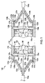
- FIG. 1 is a cross-sectional view of an undersea equipment housing, consistent with one embodiment of the present invention.
- an undersea equipment housing 100 with molded terminations is used to house equipment 102, such as optical and/or electrical equipment, in an undersea environment.
- the exemplary embodiment of the housing 100 is shown with break lines 10a, 10b indicating that the housing 100 may vary in size.
- the undersea equipment housing 100 may be connected between undersea fiber optic cables 104a, 104b.
- the undersea equipment housing 100 is used to house optical and electrical equipment 102 such as optical amplifiers in a repeater.
- the undersea equipment housing 100 may also be used to house other types of equipment such as splices in a cable joint.
- the undersea equipment housing 100 includes an inner housing 110, first and second molded terminations 120a, 120b and an outer strength housing 130.
- the inner housing 110 has first and second ends 112a, 112b and may be generally cylindrical in shape.
- the inner housing 110 may be made of a metallic material, such as steel.
- the inner housing 110 houses the optical and electrical equipment 102, which may be secured to a shelf 106.
- annular rings 116a, 116b extend inwardly from the inner housing 110, and the shelf 106 with optical and electrical equipment 102 is positioned between the annular rings 116a, 116b.
- the inside of the housing 100 is also shown with break lines 20a, 22a and 20b, 22b, indicating that the length of this area inside of the housing 100 may also vary.
- First and second molded terminations 120a, 120b are connected to the first and second ends 112a, 112b of the inner housing 110.
- the molded terminations 120a, 120b may include cable terminating structures 121a, 121b that are overmolded with a dielectric material such as polyethylene using techniques known to those skilled in the art.
- the cable terminating structures 121a, 121b may receive and terminate the ends of cables 104a, 104b using cable termination arrangements known to those skilled in the art.
- the cables 104a, 104b may include strength members (not shown), which are secured to the cable terminating structures 121a, 121b.
- the molded terminations 120a, 120b may include inside portions 122a, 122b that are located inside of the respective first and second ends 112a, 112b of the inner housing 110.
- the inside portions 122a, 122b are positioned against the respective annular rings 116a, 116b.
- Retaining rings 124a, 124b, 126a, 126b or other retaining structures may be used to secure the inside portions 122a, 122b against the respective annular rings 116a, 116b.
- the inside portions 122a, 122b may be sealed against the respective annular rings 116a, 116b, thereby hermetically sealing the inside of the housing 100.
- One or more sealing members 127a, 127b, 129a, 129b may also be positioned between the inside portions 122a, 122b of the molded terminations 120a, 120b, respectively, and the inside surface of the inner housing 110.
- the molded terminations 120a, 120b may also include outside portions 128a, 128b extending outside of the inner housing 110.
- the outside portions 128a, 128b are generally conically shaped conforming to the shape of the cable terminating structures 121a, 121b.
- the illustrated embodiment shows specific shapes and configurations, those skilled in the art will recognize that the molded terminations may have other shapes or configurations.
- the molded terminations 120a, 120b advantageously provide voltage isolation between the terminated cable ends and the inner housing 110 and the outer strength housing 130.
- the undersea equipment housing 100 may also include a molded portion 140 positioned inside of the inner housing 110 and molded portions 142a, 142b positioned inside of the annular rings 116a, 116b.
- the molded portions 140, 142a, 142b may also be made of a dielectric material such as polyethylene and provide voltage isolation between the optical and electrical equipment 102 and the inner housing 110.
- the outer strength housing 130 is located outside of the inner housing 110 and the molded terminations 120a, 120b and may also be generally cylindrical in shape.
- the outer strength housing 130 may be made of a metallic material such as steel and may be designed to have the desired strength characteristics.
- the outer strength housing 130 may include multiple strength housing pieces that are secured together, for example, outside pieces 132a, 132b, end pieces 134a, 134b and one or more intermediate pieces 136.
- the end pieces 134a, 134b may include engaging portions 138a, 138b that extend over the ends 112a, 112b of the inner housing 110 and engage the outside pieces 132a, 132b of the strength housing 130.
- the end pieces 134a, 134b may be threaded, at the other ends 139a, 139b, to the intermediate piece 136.
- the end pieces 134a, 134b may also be pinned or compressed and held together by other means.
- the outer strength housing 130 is designed to provide protection and to secure the housing from cable tension. Although the illustrated embodiment shows a five piece structure having a particular shape and configuration, those skilled in the art will recognize that the strength housing may have other shapes and configurations.
- the design of the undersea equipment housing 100 allows certain components in conventional repeaters to be eliminated, thereby reducing the size of the repeater.
- the design of the undersea equipment housing 100 can also be varied in size easily, for example, by varying the length of the inner housing 110 and strength housing 130.
- the optical and electrical equipment 102 may be positioned within the inner housing 110, for example, between the annular rings 116a, 116b.
- the ends of the cables 104a, 104b may be secured to the molded terminations 120a, 120b with the outside pieces 132a, 132b positioned over the molded terminations 120a, 120b.
- the molded terminations 120a, 120b may then be positioned inside the respective ends 112a, 112b of the inner housing 110 and secured, for example, using the retaining rings 124a, 124b, 126a, 126b.
- the intermediate piece 136 of the strength housing 130 may be positioned over the inner housing 110.
- the end pieces 134a, 134b of the strength housing 130 may then be positioned over the outside pieces 132a, 132b and secured to the intermediate piece 136.
- steps for assembling the housing 100 may be performed in different sequences and additional steps may also be performed.
- an undersea equipment housing includes an inner housing for housing optical and electronic equipment.
- First and second molded terminations are configured to be secured to respective first and second ends of the inner housing for receiving and terminating ends of a cable. At least a portion of each of the molded terminations is configured to be located inside of the respective first and second ends of the inner housing.
- An outer strength housing is configured to be located outside of the inner housing and the first and second molded terminations.
- a repeater includes an inner housing having first and second ends and repeater optical and electrical equipment housed in the inner housing.
- First and second molded terminations are secured to respective first and second ends of the inner housing for receiving and terminating ends of a cable.
- An outer strength housing is located outside of the inner housing and the first and second molded terminations.
Landscapes
- Physics & Mathematics (AREA)
- General Physics & Mathematics (AREA)
- Optics & Photonics (AREA)
- Engineering & Computer Science (AREA)
- Power Engineering (AREA)
- Cable Accessories (AREA)
- Light Guides In General And Applications Therefor (AREA)
Claims (13)
- Untersee-Ausrüstungsgehäuse (100), das Folgendes umfasst:ein inneres Gehäuse (110) zum Aufnehmen von optischer und elektronischer Ausrüstung (102), wobei das innere Gehäuse (110) ein erstes und ein zweites Ende (112a, 112b) hat,wobei das innere Gehäuse (110) einen ersten und einen zweiten ringförmigen Ring (116a, 116b) einschließt, die sich nach innen erstrecken,einen ersten und einen zweiten Endteil (120a, 120b), die dafür konfiguriert sind, an dem jeweiligen ersten bzw. zweiten Ende (112a, 112b) des inneren Gehäuses (110) befestigt zu werden, wobei wenigstens ein Abschnitt der Endteile (120a, 120b) dafür konfiguriert ist, innerhalb des jeweiligen ersten bzw. zweiten Endes (112a, 112b) des inneren Gehäuses (110) angeordnet zu werden, undein äußeres Druckgehäuse (130), das dafür konfiguriert ist, außerhalb des inneren Gehäuses (110) und des ersten und des zweiten Endteils (120a, 120b) angeordnet zu werden, dadurch gekennzeichnet, dassder erste und der zweite ringförmige Ring (116a, 116b) jeder eine Fläche haben, die dem jeweiligen ersten bzw. zweiten Ende (112a, 112b) gegenüberliegt,der erste und der zweite Endteil jeweils ein erster bzw. zweiter geformter Anschluss (120a, 120b) sind, wobei der erste und der zweite geformte Anschluss (120a, 120b) zum Aufnehmen und Anschließen von Enden eines Kabels (104a, 104b) dienen und gegenüber den jeweiligen Flächen des ersten bzw. zweiten ringförmigen Rings (116a, 116b) abgedichtet sind, wobei die geformten Anschlüsse (120a, 120b) jeder eine Kabelanschluss-Struktur (121a, 121b) einschließen, die mit einem dielektrischen Werkstoff überformt ist, und Spannung von dem inneren Gehäuse (110) und dem Druckgehäuse (130) isolieren, unddas äußere Druckgehäuse (130) eine gesamte Länge des inneren Gehäuses (110) abdeckt.
- Untersee-Ausrüstungsgehäuse nach Anspruch 1, wobei die ringförmigen Ringe (116a, 116b) derart konfiguriert sind, dass die optische und elektrische Ausrüstung (102) zwischen den ringförmigen Ringen (116a, 116b) angeordnet ist.
- Untersee-Ausrüstungsgehäuse nach Anspruch 1 oder 2, das Rückhalteringe (124a, 124b, 126a, 126b) einschließt, die zwischen das erste und das zweite Ende (112a, 112b) des inneren Gehäuses (110) und jeweilige innenseitige Abschnitte (122a, 122b) des ersten bzw. zweiten geformten Anschlusses (120a, 120b) gekoppelt sind, wobei die Rückhalteringe (124a, 124b, 126a, 126b) die innenseitigen Abschnitte (122a, 122b) des ersten und des zweiten geformten Anschlusses (120a, 120b) gegenüber dem jeweiligen ersten bzw. zweiten ringförmigen Ring (116a, 116b) sichern.
- Untersee-Ausrüstungsgehäuse nach einem der vorhergehenden Ansprüche, das einen geformten dielektrischen Abschnitt (140) einschließt, der innerhalb des inneren Gehäuses (110) angeordnet ist.
- Untersee-Ausrüstungsgehäuse nach einem der vorhergehenden Ansprüche, wobei das Druckgehäuse (130) mehrere Druckgehäuseteile (134a, 134b, 136) einschließt, die miteinander verbunden sind.
- Untersee-Ausrüstungsgehäuse nach einem der vorhergehenden Ansprüche, das geformte dielektrische Abschnitte (142a, 142b) einschließt, die innerhalb der ringförmigen Ringe (116a, 116b) angeordnet sind.
- Untersee-Ausrüstungsgehäuse nach einem der vorhergehenden Ansprüche, wobei das Druckgehäuse (130) Folgendes umfasst:ein Zwischenstück (136), das über einem Zwischenabschnitt des inneren Gehäuses (110) angeordnet ist,ein erstes und ein zweites Endstück (134a, 134b), die über dem jeweiligen ersten bzw. zweiten Ende (112a, 112b) des inneren Gehäuses (110) angeordnet und an das Zwischenstück (136) gekoppelt sind, undein erstes und ein zweites außenseitiges Stück (132a, 132b), die über dem jeweiligen ersten bzw. zweiten geformten Anschluss (120a, 120b) angeordnet und an das jeweilige erste bzw. zweite Endstück (134a, 134b) gekoppelt sind.
- Zwischenverstärker (100), der Folgendes umfasst:das Untersee-Ausrüstungsgehäuse nach Anspruch 1,optische und elektrische Verstärkerausrüstung (102), die in dem inneren Gehäuse (110) untergebracht ist, wobeider erste und der zweite Endteil (120a, 120b) an dem jeweiligen ersten bzw. zweiten Ende (112a, 112b) des inneren Gehäuses (110) befestigt sind, wenigstens ein Abschnitt der Endteile (120a, 120b) innerhalb des jeweiligen ersten bzw. zweiten Endes (112a, 112b) des inneren Gehäuses (110) angeordnet ist unddas äußere Druckgehäuse (130) außerhalb des inneren Gehäuses (110) und des ersten und des zweiten Endteils (120a, 120b) angeordnet ist.
- Zwischenverstärker nach Anspruch 8, wobei die optische und elektrische Ausrüstung (102) zwischen den ringförmigen Ringen (116a, 116b) angeordnet ist.
- Zwischenverstärker nach Anspruch 8 oder 9, der einen geformten dielektrischen Abschnitt (140) einschließt, der innerhalb des inneren Gehäuses (110) angeordnet ist.
- Zwischenverstärker nach Anspruch 8, 9 oder 10, wobei das Druckgehäuse (130) mehrere Druckgehäuseteile (134a, 134b, 136) einschließt, die miteinander verbunden sind.
- Zwischenverstärker nach einem der Ansprüche 8 bis 11, der Rückhalteringe (124a, 124b, 126a, 126b) einschließt, die zwischen das erste und das zweite Ende (112a, 112b) des inneren Gehäuses (110) und jeweilige innenseitige Abschnitte (122a, 122b) des ersten bzw. zweiten geformten Anschlusses (120a, 120b) gekoppelt sind, wobei die Rückhalteringe (124a, 124b, 126a, 126b) die innenseitigen Abschnitte (122a, 122b) des ersten und des zweiten geformten Anschlusses (120a, 120b) gegenüber dem jeweiligen ersten bzw. zweiten ringförmigen Ring (116a, 116b) sichern.
- Zwischenverstärker nach einem der Ansprüche 8 bis 12, wobei das Druckgehäuse (130) Folgendes umfasst:ein Zwischenstück (136), das über einem Zwischenabschnitt des inneren Gehäuses (110) angeordnet ist,ein erstes und ein zweites Endstück (134a, 134b), die über dem jeweiligen ersten bzw. zweiten Ende (112a, 112b) des inneren Gehäuses (110) angeordnet und an das Zwischenstück (136) gekoppelt sind, undein erstes und ein zweites außenseitiges Stück (132a, 132b), die über dem jeweiligen ersten bzw. zweiten geformten Anschluss (120a, 120b) angeordnet und an das jeweilige erste bzw. zweite Endstück (134a, 134b) gekoppelt sind.
Applications Claiming Priority (1)
| Application Number | Priority Date | Filing Date | Title |
|---|---|---|---|
| US11/221,572 US7278789B2 (en) | 2005-09-08 | 2005-09-08 | Undersea equipment housing with molded terminations |
Publications (2)
| Publication Number | Publication Date |
|---|---|
| EP1762872A1 EP1762872A1 (de) | 2007-03-14 |
| EP1762872B1 true EP1762872B1 (de) | 2011-09-07 |
Family
ID=37622295
Family Applications (1)
| Application Number | Title | Priority Date | Filing Date |
|---|---|---|---|
| EP06120266A Not-in-force EP1762872B1 (de) | 2005-09-08 | 2006-09-07 | Gehäuse für Unterseeausrüstung mit vergossenen Kabelenden |
Country Status (5)
| Country | Link |
|---|---|
| US (1) | US7278789B2 (de) |
| EP (1) | EP1762872B1 (de) |
| JP (1) | JP5388321B2 (de) |
| AU (1) | AU2006209685B2 (de) |
| CA (1) | CA2557434C (de) |
Families Citing this family (6)
| Publication number | Priority date | Publication date | Assignee | Title |
|---|---|---|---|---|
| US8328431B2 (en) * | 2010-02-01 | 2012-12-11 | Tyco Electronics Subsea Communications Llc | Coupling multiple conductor undersea optical cables to an undersea device with an isolated bypass conductive path across the undersea device |
| CN102147514B (zh) * | 2010-10-21 | 2013-01-23 | 华为技术有限公司 | 海底光缆设备的绝缘抗压筒体、海底光缆设备及制造方法 |
| US9557512B2 (en) * | 2013-03-26 | 2017-01-31 | Afl Telecommunications Llc | High pressure splice housing |
| EP3034561B1 (de) * | 2014-12-19 | 2019-02-06 | NKT HV Cables GmbH | Verfahren zur Herstellung einer Hochspannungsgleichstromkabelverbindung und Hochspannungsgleichstromkabelverbindung |
| EP3304665B1 (de) * | 2015-06-02 | 2020-08-12 | NKT HV Cables AB | Steife verbindungsanordnung |
| US11044015B2 (en) * | 2018-11-20 | 2021-06-22 | Google Llc | Low signal to noise ratio submarine communication system |
Family Cites Families (31)
| Publication number | Priority date | Publication date | Assignee | Title |
|---|---|---|---|---|
| GB742837A (en) | 1953-07-06 | 1956-01-04 | Vickers Armstrongs Ltd | Improvements in or relating to sealing devices |
| GB870743A (en) | 1958-09-03 | 1961-06-21 | Pirelli | Improvements in or relating to flexible repeaters for submarine telecommunication cables |
| US4064358A (en) | 1975-07-22 | 1977-12-20 | International Standard Electric Corporation | Termination for connecting a submarine coaxial cable to a submergible housing |
| US4172212A (en) * | 1978-07-24 | 1979-10-23 | International Telephone And Telegraph Corporation | Submarine housing for submarine cable system repeater components or the like |
| US4606603A (en) * | 1983-04-07 | 1986-08-19 | Lockheed Corporation | Underwater connector including integral bladder and seal with a set of constricting means |
| GB8320947D0 (en) | 1983-08-03 | 1983-09-07 | British Telecomm | Chamber assembly |
| JPS6068302A (ja) | 1983-09-26 | 1985-04-18 | Fujitsu Ltd | 光海底ケ−ブル用ジョイントボックス |
| US4682848A (en) * | 1984-10-03 | 1987-07-28 | Lockheed Corporation | Underwater-mateable optical fiber connector |
| IT1184648B (it) * | 1985-06-26 | 1987-10-28 | Pirelli Cavi Spa | Linea sottomarina per telecomunicazioni a firbre ottiche |
| US4785139A (en) | 1986-05-30 | 1988-11-15 | American Telephone And Telegraph Company, At&T Bell Laboratories | Cable with flexible high pressure equipment enclosure material and method of constructing same |
| US5000536A (en) | 1986-07-21 | 1991-03-19 | At&T Bell Laboratories | Connector for optical fiber cable |
| FR2606963B1 (fr) | 1986-11-14 | 1989-01-13 | Cit Alcatel | Boitier de repeteur sous-marin |
| FR2607939B1 (fr) * | 1986-12-05 | 1989-02-03 | Cables De Lyon Geoffroy Delore | Boite de raccordement pour cables a fibres optiques |
| FR2630575B1 (fr) | 1988-04-21 | 1990-07-13 | Cit Alcatel | Boitier pour equipement submersible |
| GB2229545B (en) | 1989-03-21 | 1993-04-28 | Stc Plc | Jointing optical fibre cables |
| JPH02250278A (ja) | 1989-03-23 | 1990-10-08 | Fujitsu Ltd | 海底中継器と海底ケーブルの接続構造 |
| GB8925819D0 (en) | 1989-11-15 | 1990-01-04 | Stc Plc | Flexible cable termination |
| JPH04101102A (ja) | 1990-08-21 | 1992-04-02 | Fujitsu Ltd | 光海底中継器の放熱・緩衝構造 |
| US5266742A (en) | 1991-05-23 | 1993-11-30 | Siemens Aktiengesellschaft | Longitudinal water-tight cable sleeve |
| JP2861788B2 (ja) | 1994-02-18 | 1999-02-24 | 日本電気株式会社 | 海底中継器の実装構造 |
| DE19547523C1 (de) * | 1995-12-08 | 1997-05-07 | Siemens Ag | Verschlußteil |
| US6028974A (en) | 1998-08-10 | 2000-02-22 | Alcatel | Seal for underwater cable joint |
| US6381394B1 (en) | 1999-09-03 | 2002-04-30 | Tycom (Us) Inc. | Method and apparatus for assembling an amplifier assembly |
| US6571042B1 (en) | 2000-09-26 | 2003-05-27 | Tyco Telecommunications (Us) Inc. | Multi-body modular repeater system and articulated housing for use therewith |
| US6836609B2 (en) | 2001-01-25 | 2004-12-28 | Tyco Telecommunications (Us) Inc. | Gas blocking device for optical fiber repeater |
| US6584253B2 (en) * | 2001-02-02 | 2003-06-24 | Tyco Telecommunications (Us) Inc. | Sealed cable connection |
| US6534712B1 (en) * | 2001-10-03 | 2003-03-18 | Corvis Corporation | Pressure vessel joint for repeaters in submarine optical communication systems |
| US7529020B2 (en) | 2002-11-19 | 2009-05-05 | Huawei Marine Networks Co., Ltd. | Optical amplifier module housed in a universal cable joint for an undersea optical transmission system |
| US20040175092A1 (en) | 2002-12-19 | 2004-09-09 | Young Mark K. | Hermetically sealed optical amplifier module to be integrated into a pressure vessel for undersea applications |
| US6950229B2 (en) * | 2003-11-17 | 2005-09-27 | Red Sky Systems, Inc. | Electrical insulating ring located between an end cap and a tension sleeve of an undersea pressure vessel housing an optical amplifier module |
| US7068419B2 (en) * | 2004-03-12 | 2006-06-27 | Red Sky Subsea Ltd. | Overmolded, ultra-small form factor optical repeater |
-
2005
- 2005-09-08 US US11/221,572 patent/US7278789B2/en not_active Expired - Lifetime
-
2006
- 2006-08-29 CA CA2557434A patent/CA2557434C/en not_active Expired - Fee Related
- 2006-09-06 AU AU2006209685A patent/AU2006209685B2/en not_active Ceased
- 2006-09-07 EP EP06120266A patent/EP1762872B1/de not_active Not-in-force
- 2006-09-08 JP JP2006243835A patent/JP5388321B2/ja not_active Expired - Fee Related
Also Published As
| Publication number | Publication date |
|---|---|
| AU2006209685A1 (en) | 2007-03-22 |
| US20070053645A1 (en) | 2007-03-08 |
| CA2557434A1 (en) | 2007-03-08 |
| JP2007072469A (ja) | 2007-03-22 |
| US7278789B2 (en) | 2007-10-09 |
| EP1762872A1 (de) | 2007-03-14 |
| AU2006209685B2 (en) | 2011-12-15 |
| JP5388321B2 (ja) | 2014-01-15 |
| CA2557434C (en) | 2013-03-19 |
Similar Documents
| Publication | Publication Date | Title |
|---|---|---|
| US7357579B2 (en) | Connection device with a cable gland having housing parts enabling relative movement therebetween | |
| EP0878722B1 (de) | Wellenlängenmultiplex-verzweigungseinheit und Betriebsverfahren eines optischen Übertragungssystem | |
| AU2014216341B2 (en) | Self engaging port plug | |
| KR20100112085A (ko) | 연결 시스템 | |
| US5735711A (en) | Cable connector | |
| US6665477B2 (en) | Undersea optical fiber telecommunication system and method | |
| CA2557434C (en) | Undersea equipment housing with molded terminations | |
| EP2354828B1 (de) | Umgossener LWL-Verstärker mit ultrakleinem Formfaktor | |
| US6290399B1 (en) | Optical submarine branching unit | |
| CA2510832A1 (en) | Hermetically sealed optical amplifier module to be integrated into a pressure vessel | |
| US9407073B2 (en) | Guiding support and kit for terminating a transmission cable | |
| US6508594B1 (en) | Optical plug connector | |
| JP4454500B2 (ja) | 海底光学トランスミッションシステム用の自在ケーブル継手に内蔵された光学増幅器モジュール | |
| EP4187300B1 (de) | Kabelbefestigungsvorrichtung | |
| US10969557B1 (en) | Optical fiber shuffle | |
| US7489438B1 (en) | Dielectric coating for an optical repeater pressure vessel | |
| EP3786676B1 (de) | Mehrfaserverbinder für telekommunikationsgehäuse | |
| WO2006024043A2 (en) | Undersea optical amplifier module having coupled outboard splice enclosures | |
| JP2003161843A (ja) | 海底機器の光ファイバ導入部構造 |
Legal Events
| Date | Code | Title | Description |
|---|---|---|---|
| PUAI | Public reference made under article 153(3) epc to a published international application that has entered the european phase |
Free format text: ORIGINAL CODE: 0009012 |
|
| AK | Designated contracting states |
Kind code of ref document: A1 Designated state(s): AT BE BG CH CY CZ DE DK EE ES FI FR GB GR HU IE IS IT LI LT LU LV MC NL PL PT RO SE SI SK TR |
|
| AX | Request for extension of the european patent |
Extension state: AL BA HR MK YU |
|
| 17P | Request for examination filed |
Effective date: 20070912 |
|
| 17Q | First examination report despatched |
Effective date: 20071010 |
|
| AKX | Designation fees paid |
Designated state(s): DE FR GB IT |
|
| RAP1 | Party data changed (applicant data changed or rights of an application transferred) |
Owner name: TYCO TELECOMMUNICATIONS (US) INC. |
|
| RAP1 | Party data changed (applicant data changed or rights of an application transferred) |
Owner name: TYCO ELECTRONICS SUBSEA COMMUNICATIONS LLC |
|
| RAP1 | Party data changed (applicant data changed or rights of an application transferred) |
Owner name: TYCO ELECTRONICS SUBSEA COMMUNICATIONS LLC |
|
| GRAP | Despatch of communication of intention to grant a patent |
Free format text: ORIGINAL CODE: EPIDOSNIGR1 |
|
| GRAS | Grant fee paid |
Free format text: ORIGINAL CODE: EPIDOSNIGR3 |
|
| GRAA | (expected) grant |
Free format text: ORIGINAL CODE: 0009210 |
|
| REG | Reference to a national code |
Ref country code: GB Ref legal event code: FG4D |
|
| REG | Reference to a national code |
Ref country code: DE Ref legal event code: R096 Ref document number: 602006024146 Country of ref document: DE Effective date: 20111110 |
|
| PLBE | No opposition filed within time limit |
Free format text: ORIGINAL CODE: 0009261 |
|
| STAA | Information on the status of an ep patent application or granted ep patent |
Free format text: STATUS: NO OPPOSITION FILED WITHIN TIME LIMIT |
|
| 26N | No opposition filed |
Effective date: 20120611 |
|
| REG | Reference to a national code |
Ref country code: DE Ref legal event code: R097 Ref document number: 602006024146 Country of ref document: DE Effective date: 20120611 |
|
| REG | Reference to a national code |
Ref country code: FR Ref legal event code: PLFP Year of fee payment: 11 |
|
| REG | Reference to a national code |
Ref country code: FR Ref legal event code: PLFP Year of fee payment: 12 |
|
| REG | Reference to a national code |
Ref country code: FR Ref legal event code: PLFP Year of fee payment: 13 |
|
| PGFP | Annual fee paid to national office [announced via postgrant information from national office to epo] |
Ref country code: IT Payment date: 20180629 Year of fee payment: 15 |
|
| REG | Reference to a national code |
Ref country code: DE Ref legal event code: R082 Ref document number: 602006024146 Country of ref document: DE Representative=s name: MARKS & CLERK (LUXEMBOURG) LLP, LU Ref country code: DE Ref legal event code: R081 Ref document number: 602006024146 Country of ref document: DE Owner name: SUBCOM, LLC (N.D.GES.D. STAATES DELAWARE), EAT, US Free format text: FORMER OWNER: TYCO ELECTRONICS SUBSEA COMMUNICATIONS LLC, MORRISTOWN, N.J., US |
|
| PGFP | Annual fee paid to national office [announced via postgrant information from national office to epo] |
Ref country code: FR Payment date: 20190815 Year of fee payment: 14 |
|
| PGFP | Annual fee paid to national office [announced via postgrant information from national office to epo] |
Ref country code: GB Payment date: 20190905 Year of fee payment: 14 |
|
| REG | Reference to a national code |
Ref country code: DE Ref legal event code: R119 Ref document number: 602006024146 Country of ref document: DE |
|
| PG25 | Lapsed in a contracting state [announced via postgrant information from national office to epo] |
Ref country code: DE Free format text: LAPSE BECAUSE OF NON-PAYMENT OF DUE FEES Effective date: 20200401 |
|
| GBPC | Gb: european patent ceased through non-payment of renewal fee |
Effective date: 20200907 |
|
| PG25 | Lapsed in a contracting state [announced via postgrant information from national office to epo] |
Ref country code: FR Free format text: LAPSE BECAUSE OF NON-PAYMENT OF DUE FEES Effective date: 20200930 |
|
| PG25 | Lapsed in a contracting state [announced via postgrant information from national office to epo] |
Ref country code: GB Free format text: LAPSE BECAUSE OF NON-PAYMENT OF DUE FEES Effective date: 20200907 |
|
| PG25 | Lapsed in a contracting state [announced via postgrant information from national office to epo] |
Ref country code: IT Free format text: LAPSE BECAUSE OF NON-PAYMENT OF DUE FEES Effective date: 20200907 |