EP4187300B1 - Kabelbefestigungsvorrichtung - Google Patents
Kabelbefestigungsvorrichtung Download PDFInfo
- Publication number
- EP4187300B1 EP4187300B1 EP22209735.4A EP22209735A EP4187300B1 EP 4187300 B1 EP4187300 B1 EP 4187300B1 EP 22209735 A EP22209735 A EP 22209735A EP 4187300 B1 EP4187300 B1 EP 4187300B1
- Authority
- EP
- European Patent Office
- Prior art keywords
- seal
- cable
- attachment device
- closure
- retaining arrangement
- Prior art date
- Legal status (The legal status is an assumption and is not a legal conclusion. Google has not performed a legal analysis and makes no representation as to the accuracy of the status listed.)
- Active
Links
Images




Classifications
-
- H—ELECTRICITY
- H02—GENERATION; CONVERSION OR DISTRIBUTION OF ELECTRIC POWER
- H02G—INSTALLATION OF ELECTRIC CABLES OR LINES, OR OF COMBINED OPTICAL AND ELECTRIC CABLES OR LINES
- H02G15/00—Cable fittings
- H02G15/007—Devices for relieving mechanical stress
-
- G—PHYSICS
- G02—OPTICS
- G02B—OPTICAL ELEMENTS, SYSTEMS OR APPARATUS
- G02B6/00—Light guides; Structural details of arrangements comprising light guides and other optical elements, e.g. couplings
- G02B6/44—Mechanical structures for providing tensile strength and external protection for fibres, e.g. optical transmission cables
- G02B6/4439—Auxiliary devices
- G02B6/4471—Terminating devices ; Cable clamps
-
- G—PHYSICS
- G02—OPTICS
- G02B—OPTICAL ELEMENTS, SYSTEMS OR APPARATUS
- G02B6/00—Light guides; Structural details of arrangements comprising light guides and other optical elements, e.g. couplings
- G02B6/44—Mechanical structures for providing tensile strength and external protection for fibres, e.g. optical transmission cables
- G02B6/4439—Auxiliary devices
- G02B6/4471—Terminating devices ; Cable clamps
- G02B6/4477—Terminating devices ; Cable clamps with means for strain-relieving to interior strengths element
-
- G—PHYSICS
- G02—OPTICS
- G02B—OPTICAL ELEMENTS, SYSTEMS OR APPARATUS
- G02B6/00—Light guides; Structural details of arrangements comprising light guides and other optical elements, e.g. couplings
- G02B6/44—Mechanical structures for providing tensile strength and external protection for fibres, e.g. optical transmission cables
- G02B6/4439—Auxiliary devices
- G02B6/4471—Terminating devices ; Cable clamps
- G02B6/44775—Cable seals e.g. feed-through
-
- H—ELECTRICITY
- H02—GENERATION; CONVERSION OR DISTRIBUTION OF ELECTRIC POWER
- H02G—INSTALLATION OF ELECTRIC CABLES OR LINES, OR OF COMBINED OPTICAL AND ELECTRIC CABLES OR LINES
- H02G15/00—Cable fittings
- H02G15/013—Sealing means for cable inlets
-
- G—PHYSICS
- G02—OPTICS
- G02B—OPTICAL ELEMENTS, SYSTEMS OR APPARATUS
- G02B6/00—Light guides; Structural details of arrangements comprising light guides and other optical elements, e.g. couplings
- G02B6/44—Mechanical structures for providing tensile strength and external protection for fibres, e.g. optical transmission cables
- G02B6/4439—Auxiliary devices
- G02B6/4459—Ducts; Conduits; Hollow tubes for air blown fibres
-
- H—ELECTRICITY
- H02—GENERATION; CONVERSION OR DISTRIBUTION OF ELECTRIC POWER
- H02G—INSTALLATION OF ELECTRIC CABLES OR LINES, OR OF COMBINED OPTICAL AND ELECTRIC CABLES OR LINES
- H02G1/00—Methods or apparatus specially adapted for installing, maintaining, repairing or dismantling electric cables or lines
- H02G1/06—Methods or apparatus specially adapted for installing, maintaining, repairing or dismantling electric cables or lines for laying cables, e.g. laying apparatus on vehicle
- H02G1/08—Methods or apparatus specially adapted for installing, maintaining, repairing or dismantling electric cables or lines for laying cables, e.g. laying apparatus on vehicle through tubing or conduit, e.g. rod or draw wire for pushing or pulling
- H02G1/086—Methods or apparatus specially adapted for installing, maintaining, repairing or dismantling electric cables or lines for laying cables, e.g. laying apparatus on vehicle through tubing or conduit, e.g. rod or draw wire for pushing or pulling using fluid as pulling means, e.g. liquid, pressurised gas or suction means
-
- H—ELECTRICITY
- H02—GENERATION; CONVERSION OR DISTRIBUTION OF ELECTRIC POWER
- H02G—INSTALLATION OF ELECTRIC CABLES OR LINES, OR OF COMBINED OPTICAL AND ELECTRIC CABLES OR LINES
- H02G3/00—Installations of electric cables or lines or protective tubing therefor in or on buildings, equivalent structures or vehicles
- H02G3/02—Details
- H02G3/06—Joints for connecting lengths of protective tubing or channels, to each other or to casings, e.g. to distribution boxes; Ensuring electrical continuity in the joint
- H02G3/0616—Joints for connecting tubing to casing
- H02G3/0625—Joints for connecting tubing to casing with means for preventing disengagement of conductors
- H02G3/0675—Joints for connecting tubing to casing with means for preventing disengagement of conductors with bolts operating in a direction parallel to the conductors
Definitions
- the present invention relates to a cable attachment device for inserting a telecommunication cable containing optical fibers, copper wires or coax cable into a telecommunications enclosure, for example into a terminal closure, pre-stubbed terminal, optical network terminal or other junction box.
- Telecommunication cables are ubiquitous and used for distributing all manner of data across vast networks.
- the majority of cables are electrically conductive cables (typically copper), although the use of optical fiber cables is growing rapidly in telecommunication systems as larger and larger amounts of data are transmitted. Additionally, as data transmissions increase, the fiber optic network is being extended closer to the end user which can be a premise, business, or a private residence.
- FTTX fiber to the X
- FTTP fiber to the premise
- FTTH fiber to the home
- FTTA fiber to the antenna
- optical fiber is brought to the end user and connected to the optical network terminal (ONT) unit mounted on a wall at the end user.
- the ONT converts this optical signal into conventional electrical signals to provide voice (telephone), Internet (data) and video signals to the end user.
- Blown Fiber is a technology used to deploy FTTH in many countries.
- Protective tubes or ducts are lain in the ground and the fiber-optic cables are then installed by being blown through the protective tube by a medium such as air or water.
- Fiber terminals are one type of telecommunication enclosure that is typically located near an end user in a FTTP network to distribute the final service to the end user.
- Typical fiber terminals are designed to drop services (to provide service connections) to a small number of premises having typically between four to twelve end users.
- the last service connection from the fiber terminal is made to the ONT, located at the end user using a drop cable.
- an optical connector attached to the terminal end of an optical fiber of the cable is preferred to allow quick, reliable field installation.
- a first example method of introducing a fiber-optic cable into a telecommunication enclosure is to provide a gas block or water block type connector at or near a wall of the telecommunication closure which separates the cable from the tube through which it is blown, and forms an interface between the cable and the interior of the closure.
- a protective tube or duct surrounding the fiber-optic cable is fed into one end of the connector and the exposed cable is fed out of the other end of the device and into the closure.
- a second example method of introducing a fiber-optic cable into a telecommunication enclosure is to feed a protective tube or duct surrounding a fiber-optic cable directly into a closure.
- the cable is not fixed relative to the closure. This can lead to movement of the cable within the closure, which can lead to the fibers becoming damaged. Additionally, the sealing between the cable and the tube is not adequate, and moisture can penetrate into the tube.
- US2014/0304970 discloses an apparatus for mounting blown fiber tubes, which includes a main housing mountable to an end of a flex tube, an outer ring positioned at an end of the main housing, and an inner ring positioned adjacent to and within the outer ring wherein the blown fiber tubes are positioned about an outer periphery of the inner ring.
- a trigger pushes the inner ring to compress the blown fiber tubes between the inner ring and the outer ring.
- the outer ring and the inner ring each include a plurality of spaced pockets each sized for receipt of a blown fiber tube.
- the trigger includes a threaded member which pushes the inner ring outwardly.
- portions of the inner ring separate during activation and press against the blown fiber tubes to compress the blown fiber tubes against the outer ring.
- a spring may be added to push on the inner ring.
- Anti-rotation and lock features are provided for the compression, sealing and fixation mechanisms.
- optical fiber cables are installed at an enclosure defining at least one cable port by loading a seal block assembly onto each optical fiber cable; installing and/or connecting a fixation assembly onto each optical fiber cable; and latching the seal block assembly to the enclosure.
- the cable is secured by the fixation assembly.
- the fixation assembly retains one or more types of strength members of the optical fiber cable.
- the seal block assembly snaps and/or clips into a locked position relative to the enclosure.
- a filler rod can be used to fill an unused port in the seal block assembly.
- An attachment device can be used to connect to the filler rod for adding a new tube to the seal block assembly.
- a cable attachment device for sealing and retaining a communications cable entering a telecommunications closure through an opening defined in the closure, the device comprising a housing, having a passage through which the communications cable extends, the housing having a first portion and a second portion; wherein the first portion of the housing is configured to receive a protective tube of the telecommunications cable; wherein the second portion of the housing is configured to engage with the closure; a first seal configured to form a seal between the device and the closure; a second seal configured to form a seal between the interior of the device and the protective tube; a third seal configured to seal between the communications cable and the interior of the device wherein the third seal circumscribes the communications cable; a first retaining arrangement configured to couple the device to the closure; a second retaining arrangement configured to hold the tube relative to the device; and a third retaining arrangement configured to fix the telecommunications cable relative to the device, wherein the first portion comprises an inlet portion for insertion in the telecommunications closure, and the second
- This arrangement provides the advantages of a gas block or water block type connector with those of a direct connector into a closure.
- this device provides a watertight solution which seals between the closure and the device, between the device and the tube and between the tube and the cable housed within.
- the device also prevents unwanted movement of the tube and cable by fixing both the tube and the cable within the device which can lead to damage of the fibers or other components.
- the second retaining arrangement which retains the tube within the device provides the advantage of the tube being able to remain in place if the cable needs to be replaced.
- the second portion may be partially received in the closure. Alternatively, the second portion may be fully received in the closure.
- the second retaining arrangement may still permit some movement of the tube relative to the device, such as rotational movement.
- the first seal circumscribes an outer surface of the second portion of the device housing.
- This arrangement can advantageously enable good sealing between the device and the closure as it is the second portion of the device which is received in the opening of the closure.
- Providing the seal on an outer surface of the device rather than in the opening of the closure can help to make routine maintenance operations easier for an operator. This is because the seal can be more easily replaced in case of failure.
- the cable attachment devices are intended to be replaced more often than a closure, meaning that the seal is replaced more frequently.
- Providing the seal as an integral part of the attachment device also reduces the operations needed to be made by an operator assembling the device in the closure.
- the second seal circumscribes the protective tube.
- the passage of the first portion of the housing is configured to receive the second seal.
- the first retaining arrangement is arranged on the second portion of the device housing.
- the first retaining arrangement comprises one or more resilient members that releasably engage with the closure.
- attachment device can be releasably connected to the closure. This can make assembly and disassembly easier, as well as providing an operator with more options for routine maintenance operations.
- the passage of the first portion of the housing is configured to receive the second retaining arrangement.
- the second retaining arrangement releasably engages with the tube.
- the tube when the second retaining member is engaged, the tube is able to rotate relative to the device.
- attachment device can advantageously allow the attachment device to be rotated in the closure without creating torsion in the tube. This is also advantageous for the assembly of the attachment device, where portions of the device have threaded connections and rotation of the portions is required.
- the device further comprises a second retaining member release mechanism which is configured to disengage the second retaining arrangement.
- the second retaining arrangement comprises a plurality of spaced apart resilient fingers.
- the protective tube is a duct for blown fiber and the communications cable is installed by being blown through the protective tube by a medium such as air or water.
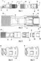
- FIG. 1 is an exploded view of an exemplary cable attachment device 1 according to an embodiment of the invention.
- the cable attachment device 1 housing has a first portion 6 and a second portion 7.
- the first portion 6 of the housing is configured to receive a protective tube of a telecommunications cable and the second portion of the housing is configured to engage with a telecommunications closure (not shown).
- the cable attachment device can also be divided into an inlet portion 10, a locknut portion 20 and a gasblock or waterblock portion 30.
- the inlet portion 10, locknut portion 20 and gasblock or waterblock portion 30 each have a respective central bore or passage.
- the device 1 has a first seal 11 on an outer surface of the inlet portion 10, configured to form a seal between the device 1 and the telecommunications closure.
- the first seal 11 is in the form of a gasket.
- the device 1 has a second seal 31 received in the gasblock or waterbock portion 30, configured to form a seal between the interior of the device 1 and the protective tube of the communications cable to be received in the device 1.
- the second seal 31 is in the form of a gasket.
- the device has a third seal 12 received in an end of the inlet portion 10, configured to seal between the communications cable and the interior of the device 1.
- the end of the inlet portion 10 has a number of resilient arms 15 that circumscribe the third seal 12 when it is inserted in the end of the inlet portion 10.
- the third seal 12 is in the form of a gasket.
- the device 1 further has a first retaining arrangement 13 configured to couple the device to the closure; a second retaining arrangement (not shown) configured to hold the tube relative to the device 1; and a third retaining arrangement 14 configured to fix the telecommunications cable relative to the device 1.
- the first retaining arrangement 13 is on the inlet portion 10 which is partially received in an opening of the closure, and is in the form of two resilient arms.
- the second retaining arrangement is received in the gasblock or waterblock portion 30 of the device 1.
- the second retaining arrangement will be described in more detail in relation to Figures 2 and 3 .
- the third retaining member 14 is on the inlet portion 10 of the device 1 and is a clamp in this example.
- the third retaining member 14 will be described in more detail in relation to Figures 15 and 16 .
- Figures 2 and 3 respectively show cross-sectional views of an assembled and exploded view of the locknut portion 20 and gasblock or waterblock 30 portion of the device 1.
- the second retaining arrangement 34 can be seen.
- the second retaining arrangement 34 is in the form of a ring with a plurality of resilient fingers which are configured to engage with the protective tube of the cable.
- An intermediate piece 32 is shown which helps to keep the second seal 31 in place in the gasblock or waterblock portion 30.
- a guide assembly 33 comprising a first guide piece 33a and a second guide piece 33b is shown which guide the tube into the gasblock or waterblock portion 30. These also help to retain the second retaining arrangement 34 in place in the gasblock or waterblock portion 30 and form the second retaining arrangement 34 release mechanism.
- the gasblock or waterblock portion 30 also has a mechanical stop 35 in the form of a narrowing of the central passage of the gasblock or waterblock portion 30. This mechanical stop 35 serves to stop the tube and prevent the tube from passing completely through the gasblock or waterblock portion 30.
- Figures 4 and 5 show a perspective view of an example intermediate piece 32.
- Figures 4 and 5 show another example of the intermediate piece 32 with an additional ring 36 which creates a uniform surface at the end of the intermediate piece 32 and helps to locate the second seal 31.
- Figures 6 to 8 show perspective views of the locknut 20 and gasblock or waterblock portion 30 at different stages of assembly.
- the tube 2 is inserted into an opening in the guide assembly 33, passes through the intermediate piece 32, the second retaining arrangement 34 and the second seal 31 and abuts the mechanical stop 35.
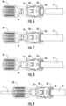
- Figures 9 to 11 show perspective views of an example cable 3 being assembled in the locknut 20 and gasblock or waterblock portion 30.
- Figure 9 shows the cable 3 being blown through the tube 2 in a medium such as air or water.
- Figure 10 shows the third seal 12 being placed over the cable 3 such that it circumscribes the cable.
- Figure 11 shows the cable 3 with the third seal 12 in place.
- a portion of the cable outer sheath which has passed through the locknut 20 and gasblock or waterblock portion 30 is stripped back to expose the fibers 4 and a strength member 5 therein.
- the strength member 5 can be cut down such that only a short length protrudes from the outer sheath of the cable 3.
- Figures 12 to 14 show perspective views of an example inlet portion 10 being assembled with the locknut portion 20 and gasblock or waterblock portion 30.
- Figure 12 shows the cable 3 and exposed fibers 4 and strength member 5 of Figure 11 being passed through the inlet portion 10, and the third seal 12 being inserted into the central bore of the inlet portion 10.
- Figure 13 shows the inlet portion 10 assembled to the locknut portion 20 and gasblock or waterblock portions 30 with an external thread of the inlet portion 10 engaged with an internal thread of the locknut portion 20.
- Figure 14 shows the third retaining arrangement 14 assembled to the inlet portion 10 and the strength member 5 of the cable retained by this third retaining arrangement 14.
- the third retaining arrangement 14 is a clamp.
- the cable is fully assembled in the cable attachment device.
- Figures 16 to 19 show a second embodiment of the locknut and gasblock or waterblock portions at different stages of assembly with a tube.
- Figure 16 is an exploded view of the locknut and gasblock or waterblock portions in which the two portions are separate components.
- the second seal 31 is placed in between the separate locknut portion 20 and gasblock or waterblock portion 30 and held in place by the threaded engagement of the locknut portion 20 with the gasblock or waterblock portion 30.
- an additional seal 21 is provided to seal between the body of the locknut portion 20 and the tube 2.
- the gasblock or waterblock portion 30 of this example also has a mechanical stop 35 to stop the tube 2 from being passed through.
- Figure 17 is an assembled perspective view of the locknut portion and gasblock or waterblock portion of Figure 16 .
- Figure 18 shows the assembled locknut portion 20 and gasblock or waterblock portion 30 of Figure 17 with a tube 2 installed.
- Figure 19 shows the assembled locknut portion 20 and gasblock or waterblock portion 30 of Figure 18 with a cable installed and stripped in the same way as is described in relation to the example of Figures 9 to 11 .
- Figures 20 to 22 show perspective views of the second embodiment of the locknut portion 20 and gasblock or waterblock portions 30 at different stages of assembly with an inlet portion 10.
- the steps of the installation of the inlet portion 10 described in relation to Figures 12 to 14 correspond respectively to the steps of Figures 20 to 22 and, for brevity will not be repeated.
- the strength member 5 of the cable is omitted from these Figures for simplicity but it will be appreciated that a strength member similar to that of Figures 12 to 14 could also be present in this embodiment.
- Figures 23 to 26 show a cable attachment device 1 according to the second embodiment, being installed in a closure 50.
- Figure 23 shows a cable attachment device 1 being installed in a closure 50.
- a portion of a closure wall 51 is shown, with an opening 52 configured to receive the first portion of the cable attachment device.
- the first retaining arrangement 13 is configured to engage with an inner surface of the wall 51 of the closure to retain the cable attachment device 1, to retain the device in the closure 50.
- Figure 24 shows the cable attachment device 1 coupled to the closure 50.
- Figure 25 is a cross sectional view of a cable attachment device 1 installed in a closure 50. This view shows how the first seal 11 forms a seal between the device 1 and the closure 50.
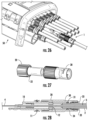
- Figure 26 is a perspective view showing a portion of a closure with a number of cable attachment devices 1 installed in openings 52 in the closure 50.
- FIGs 27 and 28 show another example of the second embodiment of the invention in which the locknut portion 20 and the gasblock or waterblock portion 30 are separate but configured to be permanently joined together by ultrasound welding or another suitable joining method.
- the locknut portion has an energy director 22 to focus the ultrasonic energy during ultrasonic welding to facilitate joining of the locknut portion 20 and the gasblock or waterblock portion 30.
- Figures 29 to 31 show a third embodiment of the locknut portion 20 and gasblock or waterblock portion 30 at different stages of assembly with a tube 2.
- the second seal 31, provided between the inside of the tube 2 and the cable 3 is in the form of a plug configured to be mounted to the end of the tube 2 and the second seal 31 has a channel through which the cable 3 can be passed.
- the locknut portion 20 and the gasblock or waterblock portion 30 form a single component.
- the second seal also has a flange 37 which engages with a mechanical stop 35 in the gasblock or waterblock portion 30 to stop the tube 2 from being passed through.
- This embodiment shares most of the features of the second embodiment and, for brevity, these will not be repeated.
- Figures 32 to 34 show various views of a third embodiment of the locknut portion and gasblock or waterblock portion being assembled with the inlet portion. These figures show that the locknut portion 20 and gasblock or waterblock portion 30 of the third embodiment is assembled with the inlet portion 10 in the same way as is described in respect of the first and second embodiments.
Landscapes
- Physics & Mathematics (AREA)
- General Physics & Mathematics (AREA)
- Optics & Photonics (AREA)
- Cable Accessories (AREA)
- Light Guides In General And Applications Therefor (AREA)
Claims (15)
- Kabelbefestigungsvorrichtung (1) zum Abdichten und Sichern eines Kommunikationskabels, das durch eine Öffnung in einen Telekommunikationsverschluss (50) eintritt, die in dem Verschluss definiert ist, wobei die Vorrichtung Folgendes aufweist:ein Gehäuse mit einem Durchgang, durch den das Kommunikationskabel (3) verläuft, wobei das Gehäuse einen ersten Teil (6) und einen zweiten Teil (7) aufweist;wobei der erste Teil (6) des Gehäuses zum Aufnehmen eines Schutzrohrs (2) des Telekommunikationskabels konfiguriert ist;wobei der zweite Teil (7) des Gehäuses konfiguriert ist, um mit dem Verschluss in Eingriff zu kommen;eine erste Dichtung (11), die zum Bilden einer Dichtung zwischen der Vorrichtung und dem Verschluss konfiguriert ist;eine zweite Dichtung (31), die zum Bilden einer Dichtung zwischen dem Inneren der Vorrichtung und dem Schutzrohr konfiguriert ist;eine dritte Dichtung (12), die zum Abdichten zwischen dem Kommunikationskabel (3) und dem Inneren der Vorrichtung konfiguriert ist, wobei die dritte Dichtung (12) das Kommunikationskabel (3) begrenzt;eine erste Sicherungsanordnung (13), die zum Koppeln der Vorrichtung mit dem Verschluss konfiguriert ist;eine zweite Sicherungsanordnung (34), die zum Halten des Schutzrohrs (2) relativ zur Vorrichtung konfiguriert ist; undeine dritte Sicherungsanordnung (14), die zum Fixieren des Kommunikationskabels (3) relativ zur Vorrichtung konfiguriert ist;wobei der zweite Teil (7) einen Einlassteil (10) zum Einführen in den Telekommunikationsverschluss (50) aufweist und der erste Teil (6) einen Sicherungsmutterteil (20) und einen Gasblockteil (30) aufweist;ein Ende des Einlassteils (10) ein zusammendrückbares Element (15) aufweist und wobei die dritte Dichtung konfiguriert ist, um in einer Bohrung des zusammendrückbaren Elements (15) aufgenommen zu werden; unddas Innere des Sicherungsmutterteils (20) so geformt ist, dass es eine Kraft auf das zusammendrückbare Element (15) des Einlassteils (10) ausübt, um die dritte Dichtung (12) zusammenzudrücken, wenn der Sicherungsmutterteil (20) mit dem Einlassteil gekoppelt ist, wobei die Dichtung zwischen dem Kommunikationskabel und dem Inneren der Vorrichtung gebildet wird.
- Kabelbefestigungsvorrichtung nach Anspruch 1, wobei die erste Dichtung (11) eine Außenfläche des zweiten Teils (7) des Vorrichtungsgehäuses begrenzt.
- Kabelbefestigungsvorrichtung nach Anspruch 1 oder Anspruch 2, wobei die zweite Dichtung (31) das Schutzrohr (2) begrenzt.
- Kabelbefestigungsvorrichtung nach einem der vorhergehenden Ansprüche, wobei der Durchgang des ersten Teils (6) des Gehäuses zum Aufnehmen der zweiten Dichtung (31) konfiguriert ist.
- Kabelbefestigungsvorrichtung nach einem der vorhergehenden Ansprüche, wobei das zusammendrückbare Element eine Mehrzahl von federnden Armen (15) aufweist, die zum Begrenzen der dritten Dichtung (12) konfiguriert sind, wenn die dritte Dichtung (12) das Kommunikationskabel (3) begrenzt und wenn die dritte Dichtung (12) in das Ende des Einlassteils (10) eingeführt ist.
- Kabelbefestigungsvorrichtung nach einem der vorhergehenden Ansprüche, wobei der Sicherungsmutterteil (20) des ersten Teils (6) und der Einlassteil (10) des zweiten Teils (7) zum Aneinanderkoppeln durch eine Schraubverbindung konfiguriert sind.
- Kabelbefestigungsvorrichtung nach einem der vorhergehenden Ansprüche, wobei die erste Sicherungsanordnung (13) am zweiten Teil (7) des Vorrichtungsgehäuses angeordnet ist und wobei die erste Sicherungsanordnung (13) ein oder mehrere federnde Elemente aufweist, die auslösbar mit dem Verschluss in Eingriff kommen.
- Kabelbefestigungsvorrichtung nach einem der vorhergehenden Ansprüche, wobei der Durchgang des ersten Teils (6) des Gehäuses zum Aufnehmen der zweiten Sicherungsanordnung (34) konfiguriert ist.
- Kabelbefestigungsvorrichtung nach Anspruch 8, wobei die zweite Sicherungsanordnung (34) auslösbar mit dem Schutzrohr (2) in Eingriff kommt.
- Kabelbefestigungsvorrichtung nach Anspruch 9, wobei, wenn die zweite Sicherungsanordnung (34) in Eingriff gebracht worden ist, das Entfernen des Schutzrohrs (2) nicht möglich ist.
- Kabelbefestigungsvorrichtung nach Anspruch 10, wobei, wenn die zweite Sicherungsanordnung (34) in Eingriff gebracht worden ist, das Schutzrohr (2) sich relativ zur Vorrichtung drehen kann.
- Kabelbefestigungsvorrichtung nach einem der Ansprüche 9 bis 11, wobei die Vorrichtung ferner einen Auslösemechanismus (33, 33b) für das zweite Sicherungselement aufweist, der konfiguriert ist, um die zweite Sicherungsanordnung (34) außer Eingriff zu bringen.
- Kabelbefestigungsvorrichtung nach Anspruch 12, wobei, wenn die zweite Sicherungsanordnung (34) außer Eingriff gebracht worden ist, das Entfernen des Schutzrohrs (2) von der Vorrichtung möglich ist.
- Kabelbefestigungsvorrichtung nach einem der vorhergehenden Ansprüche, wobei die zweite Sicherungsanordnung (34) eine Mehrzahl von voneinander beabstandeten federnden Fingern aufweist.
- Kabelbefestigungsvorrichtung nach einem der vorhergehenden Ansprüche, wobei das Schutzrohr ein Kanal für geblasene Fasern ist und das Kommunikationskabel verlegt wird, indem es mit einem Medium wie Luft oder Wasser durch das Schutzrohr geblasen wird.
Applications Claiming Priority (1)
| Application Number | Priority Date | Filing Date | Title |
|---|---|---|---|
| US202163284088P | 2021-11-30 | 2021-11-30 |
Publications (2)
| Publication Number | Publication Date |
|---|---|
| EP4187300A1 EP4187300A1 (de) | 2023-05-31 |
| EP4187300B1 true EP4187300B1 (de) | 2025-05-14 |
Family
ID=84363204
Family Applications (1)
| Application Number | Title | Priority Date | Filing Date |
|---|---|---|---|
| EP22209735.4A Active EP4187300B1 (de) | 2021-11-30 | 2022-11-25 | Kabelbefestigungsvorrichtung |
Country Status (2)
| Country | Link |
|---|---|
| US (1) | US12487426B2 (de) |
| EP (1) | EP4187300B1 (de) |
Families Citing this family (1)
| Publication number | Priority date | Publication date | Assignee | Title |
|---|---|---|---|---|
| CN117724217B (zh) * | 2024-01-02 | 2024-06-21 | 河间市瀛州电信器材有限公司 | 通信用光缆保护管 |
Family Cites Families (6)
| Publication number | Priority date | Publication date | Assignee | Title |
|---|---|---|---|---|
| US7568943B2 (en) * | 2005-07-27 | 2009-08-04 | Corning Cable Systems Llc | Sealing and retaining cable attachment for telecommunications closures |
| JP2011517274A (ja) * | 2008-04-09 | 2011-05-26 | スリーエム イノベイティブ プロパティズ カンパニー | 電気通信ケーブル入線装置 |
| EP2783250A2 (de) | 2011-11-22 | 2014-10-01 | Tyco Electronics Raychem BVBA | System und verfahren zum anbringen von geblasenen faserrohren an einem gehäuse |
| DK2856233T3 (da) | 2012-05-25 | 2021-04-26 | CommScope Connectivity Belgium BVBA | Kabelportanordninger til telekommunikationshus |
| FR2982039B1 (fr) | 2013-01-04 | 2014-05-09 | Parker Hannifin Mfg France Sas | Raccord pour circuit de fibres optiques et procede de connexion d'un tel circuit a un tel raccord |
| US11460655B2 (en) * | 2020-02-16 | 2022-10-04 | Corning Research & Development Corporation | Cable entry sealing systems for telecommunication enclosures |
-
2022
- 2022-11-17 US US17/989,167 patent/US12487426B2/en active Active
- 2022-11-25 EP EP22209735.4A patent/EP4187300B1/de active Active
Also Published As
| Publication number | Publication date |
|---|---|
| US12487426B2 (en) | 2025-12-02 |
| EP4187300A1 (de) | 2023-05-31 |
| US20230168458A1 (en) | 2023-06-01 |
Similar Documents
| Publication | Publication Date | Title |
|---|---|---|
| EP3550342B1 (de) | Faseroptischer stecker | |
| EP3660996B1 (de) | Eingangsöffnung für mechanisches kabel | |
| CN101636679B (zh) | 光纤电缆入口器件以及通信封装件系统 | |
| KR101459158B1 (ko) | 광섬유 분할기 모듈 | |
| US11579374B2 (en) | Hybrid ingress protected connector and adapter assembly | |
| CN101910902B (zh) | 通信电缆入口设备 | |
| EP2074455B1 (de) | System zum einstecken eines faseroptischen kabels in eine faseroptische buchse und kabeladapter dafür | |
| US20050254757A1 (en) | Connector port for network interface device | |
| CN113261215A (zh) | 具有防脱结构的电缆端子组件 | |
| US11041998B2 (en) | Telecommunication enclosures | |
| US20160103290A1 (en) | Distribution cable with bidirectional breakout locations | |
| US12487426B2 (en) | Cable attachment device | |
| US12461316B2 (en) | Fiber optic adapter conversion system | |
| US20260128574A1 (en) | Cable attachment system | |
| EP3786676B1 (de) | Mehrfaserverbinder für telekommunikationsgehäuse | |
| GB2631913A (en) | Block terminal |
Legal Events
| Date | Code | Title | Description |
|---|---|---|---|
| PUAI | Public reference made under article 153(3) epc to a published international application that has entered the european phase |
Free format text: ORIGINAL CODE: 0009012 |
|
| STAA | Information on the status of an ep patent application or granted ep patent |
Free format text: STATUS: THE APPLICATION HAS BEEN PUBLISHED |
|
| AK | Designated contracting states |
Kind code of ref document: A1 Designated state(s): AL AT BE BG CH CY CZ DE DK EE ES FI FR GB GR HR HU IE IS IT LI LT LU LV MC ME MK MT NL NO PL PT RO RS SE SI SK SM TR |
|
| STAA | Information on the status of an ep patent application or granted ep patent |
Free format text: STATUS: REQUEST FOR EXAMINATION WAS MADE |
|
| 17P | Request for examination filed |
Effective date: 20231127 |
|
| RBV | Designated contracting states (corrected) |
Designated state(s): AL AT BE BG CH CY CZ DE DK EE ES FI FR GB GR HR HU IE IS IT LI LT LU LV MC ME MK MT NL NO PL PT RO RS SE SI SK SM TR |
|
| GRAP | Despatch of communication of intention to grant a patent |
Free format text: ORIGINAL CODE: EPIDOSNIGR1 |
|
| STAA | Information on the status of an ep patent application or granted ep patent |
Free format text: STATUS: GRANT OF PATENT IS INTENDED |
|
| RIC1 | Information provided on ipc code assigned before grant |
Ipc: H02G 3/06 20060101ALN20241127BHEP Ipc: H02G 1/08 20060101ALN20241127BHEP Ipc: G02B 6/52 20060101ALN20241127BHEP Ipc: H02G 15/013 20060101ALI20241127BHEP Ipc: H02G 15/007 20060101ALI20241127BHEP Ipc: H02G 3/08 20060101ALI20241127BHEP Ipc: G02B 6/44 20060101AFI20241127BHEP |
|
| INTG | Intention to grant announced |
Effective date: 20241209 |
|
| GRAS | Grant fee paid |
Free format text: ORIGINAL CODE: EPIDOSNIGR3 |
|
| GRAA | (expected) grant |
Free format text: ORIGINAL CODE: 0009210 |
|
| STAA | Information on the status of an ep patent application or granted ep patent |
Free format text: STATUS: THE PATENT HAS BEEN GRANTED |
|
| AK | Designated contracting states |
Kind code of ref document: B1 Designated state(s): AL AT BE BG CH CY CZ DE DK EE ES FI FR GB GR HR HU IE IS IT LI LT LU LV MC ME MK MT NL NO PL PT RO RS SE SI SK SM TR |
|
| REG | Reference to a national code |
Ref country code: GB Ref legal event code: FG4D |
|
| REG | Reference to a national code |
Ref country code: CH Ref legal event code: EP |
|
| REG | Reference to a national code |
Ref country code: DE Ref legal event code: R096 Ref document number: 602022014603 Country of ref document: DE |
|
| REG | Reference to a national code |
Ref country code: IE Ref legal event code: FG4D |
|
| REG | Reference to a national code |
Ref country code: NL Ref legal event code: MP Effective date: 20250514 |
|
| PG25 | Lapsed in a contracting state [announced via postgrant information from national office to epo] |
Ref country code: ES Free format text: LAPSE BECAUSE OF FAILURE TO SUBMIT A TRANSLATION OF THE DESCRIPTION OR TO PAY THE FEE WITHIN THE PRESCRIBED TIME-LIMIT Effective date: 20250514 Ref country code: FI Free format text: LAPSE BECAUSE OF FAILURE TO SUBMIT A TRANSLATION OF THE DESCRIPTION OR TO PAY THE FEE WITHIN THE PRESCRIBED TIME-LIMIT Effective date: 20250514 Ref country code: PT Free format text: LAPSE BECAUSE OF FAILURE TO SUBMIT A TRANSLATION OF THE DESCRIPTION OR TO PAY THE FEE WITHIN THE PRESCRIBED TIME-LIMIT Effective date: 20250915 |
|
| REG | Reference to a national code |
Ref country code: LT Ref legal event code: MG9D |
|
| PG25 | Lapsed in a contracting state [announced via postgrant information from national office to epo] |
Ref country code: GR Free format text: LAPSE BECAUSE OF FAILURE TO SUBMIT A TRANSLATION OF THE DESCRIPTION OR TO PAY THE FEE WITHIN THE PRESCRIBED TIME-LIMIT Effective date: 20250815 Ref country code: NO Free format text: LAPSE BECAUSE OF FAILURE TO SUBMIT A TRANSLATION OF THE DESCRIPTION OR TO PAY THE FEE WITHIN THE PRESCRIBED TIME-LIMIT Effective date: 20250814 |
|
| PG25 | Lapsed in a contracting state [announced via postgrant information from national office to epo] |
Ref country code: NL Free format text: LAPSE BECAUSE OF FAILURE TO SUBMIT A TRANSLATION OF THE DESCRIPTION OR TO PAY THE FEE WITHIN THE PRESCRIBED TIME-LIMIT Effective date: 20250514 Ref country code: PL Free format text: LAPSE BECAUSE OF FAILURE TO SUBMIT A TRANSLATION OF THE DESCRIPTION OR TO PAY THE FEE WITHIN THE PRESCRIBED TIME-LIMIT Effective date: 20250514 |
|
| REG | Reference to a national code |
Ref country code: AT Ref legal event code: MK05 Ref document number: 1795255 Country of ref document: AT Kind code of ref document: T Effective date: 20250514 |
|
| PG25 | Lapsed in a contracting state [announced via postgrant information from national office to epo] |
Ref country code: BG Free format text: LAPSE BECAUSE OF FAILURE TO SUBMIT A TRANSLATION OF THE DESCRIPTION OR TO PAY THE FEE WITHIN THE PRESCRIBED TIME-LIMIT Effective date: 20250514 |
|
| PG25 | Lapsed in a contracting state [announced via postgrant information from national office to epo] |
Ref country code: HR Free format text: LAPSE BECAUSE OF FAILURE TO SUBMIT A TRANSLATION OF THE DESCRIPTION OR TO PAY THE FEE WITHIN THE PRESCRIBED TIME-LIMIT Effective date: 20250514 |
|
| PG25 | Lapsed in a contracting state [announced via postgrant information from national office to epo] |
Ref country code: AT Free format text: LAPSE BECAUSE OF FAILURE TO SUBMIT A TRANSLATION OF THE DESCRIPTION OR TO PAY THE FEE WITHIN THE PRESCRIBED TIME-LIMIT Effective date: 20250514 |
|
| PG25 | Lapsed in a contracting state [announced via postgrant information from national office to epo] |
Ref country code: RS Free format text: LAPSE BECAUSE OF FAILURE TO SUBMIT A TRANSLATION OF THE DESCRIPTION OR TO PAY THE FEE WITHIN THE PRESCRIBED TIME-LIMIT Effective date: 20250814 |
|
| PG25 | Lapsed in a contracting state [announced via postgrant information from national office to epo] |
Ref country code: IS Free format text: LAPSE BECAUSE OF FAILURE TO SUBMIT A TRANSLATION OF THE DESCRIPTION OR TO PAY THE FEE WITHIN THE PRESCRIBED TIME-LIMIT Effective date: 20250914 |
|
| PG25 | Lapsed in a contracting state [announced via postgrant information from national office to epo] |
Ref country code: LV Free format text: LAPSE BECAUSE OF FAILURE TO SUBMIT A TRANSLATION OF THE DESCRIPTION OR TO PAY THE FEE WITHIN THE PRESCRIBED TIME-LIMIT Effective date: 20250514 |
|
| PGFP | Annual fee paid to national office [announced via postgrant information from national office to epo] |
Ref country code: DE Payment date: 20251013 Year of fee payment: 4 |
|
| PG25 | Lapsed in a contracting state [announced via postgrant information from national office to epo] |
Ref country code: DK Free format text: LAPSE BECAUSE OF FAILURE TO SUBMIT A TRANSLATION OF THE DESCRIPTION OR TO PAY THE FEE WITHIN THE PRESCRIBED TIME-LIMIT Effective date: 20250514 Ref country code: SM Free format text: LAPSE BECAUSE OF FAILURE TO SUBMIT A TRANSLATION OF THE DESCRIPTION OR TO PAY THE FEE WITHIN THE PRESCRIBED TIME-LIMIT Effective date: 20250514 |
|
| PGFP | Annual fee paid to national office [announced via postgrant information from national office to epo] |
Ref country code: FR Payment date: 20251013 Year of fee payment: 4 |
|
| PG25 | Lapsed in a contracting state [announced via postgrant information from national office to epo] |
Ref country code: CZ Free format text: LAPSE BECAUSE OF FAILURE TO SUBMIT A TRANSLATION OF THE DESCRIPTION OR TO PAY THE FEE WITHIN THE PRESCRIBED TIME-LIMIT Effective date: 20250514 |
|
| PG25 | Lapsed in a contracting state [announced via postgrant information from national office to epo] |
Ref country code: EE Free format text: LAPSE BECAUSE OF FAILURE TO SUBMIT A TRANSLATION OF THE DESCRIPTION OR TO PAY THE FEE WITHIN THE PRESCRIBED TIME-LIMIT Effective date: 20250514 |
|
| PG25 | Lapsed in a contracting state [announced via postgrant information from national office to epo] |
Ref country code: SK Free format text: LAPSE BECAUSE OF FAILURE TO SUBMIT A TRANSLATION OF THE DESCRIPTION OR TO PAY THE FEE WITHIN THE PRESCRIBED TIME-LIMIT Effective date: 20250514 |
|
| PG25 | Lapsed in a contracting state [announced via postgrant information from national office to epo] |
Ref country code: IT Free format text: LAPSE BECAUSE OF FAILURE TO SUBMIT A TRANSLATION OF THE DESCRIPTION OR TO PAY THE FEE WITHIN THE PRESCRIBED TIME-LIMIT Effective date: 20250514 |
|
| REG | Reference to a national code |
Ref country code: DE Ref legal event code: R097 Ref document number: 602022014603 Country of ref document: DE |
|
| PG25 | Lapsed in a contracting state [announced via postgrant information from national office to epo] |
Ref country code: RO Free format text: LAPSE BECAUSE OF FAILURE TO SUBMIT A TRANSLATION OF THE DESCRIPTION OR TO PAY THE FEE WITHIN THE PRESCRIBED TIME-LIMIT Effective date: 20250514 |
|
| PLBE | No opposition filed within time limit |
Free format text: ORIGINAL CODE: 0009261 |
|
| STAA | Information on the status of an ep patent application or granted ep patent |
Free format text: STATUS: NO OPPOSITION FILED WITHIN TIME LIMIT |
|
| REG | Reference to a national code |
Ref country code: CH Ref legal event code: L10 Free format text: ST27 STATUS EVENT CODE: U-0-0-L10-L00 (AS PROVIDED BY THE NATIONAL OFFICE) Effective date: 20260325 |
|
| 26N | No opposition filed |
Effective date: 20260217 |