EP1761682B1 - Werkzeug-haltevorrichtung - Google Patents
Werkzeug-haltevorrichtung Download PDFInfo
- Publication number
- EP1761682B1 EP1761682B1 EP05732397A EP05732397A EP1761682B1 EP 1761682 B1 EP1761682 B1 EP 1761682B1 EP 05732397 A EP05732397 A EP 05732397A EP 05732397 A EP05732397 A EP 05732397A EP 1761682 B1 EP1761682 B1 EP 1761682B1
- Authority
- EP
- European Patent Office
- Prior art keywords
- pick
- tool
- opening
- receptacle
- holder
- Prior art date
- Legal status (The legal status is an assumption and is not a legal conclusion. Google has not performed a legal analysis and makes no representation as to the accuracy of the status listed.)
- Expired - Lifetime
Links
Images


Classifications
-
- E—FIXED CONSTRUCTIONS
- E21—EARTH OR ROCK DRILLING; MINING
- E21C—MINING OR QUARRYING
- E21C35/00—Details of, or accessories for, machines for slitting or completely freeing the mineral from the seam, not provided for in groups E21C25/00 - E21C33/00, E21C37/00 or E21C39/00
- E21C35/18—Mining picks; Holders therefor
- E21C35/19—Means for fixing picks or holders
- E21C35/197—Means for fixing picks or holders using sleeves, rings or the like, as main fixing elements
-
- E—FIXED CONSTRUCTIONS
- E21—EARTH OR ROCK DRILLING; MINING
- E21C—MINING OR QUARRYING
- E21C35/00—Details of, or accessories for, machines for slitting or completely freeing the mineral from the seam, not provided for in groups E21C25/00 - E21C33/00, E21C37/00 or E21C39/00
- E21C35/18—Mining picks; Holders therefor
- E21C35/187—Mining picks; Holders therefor with arrangement of fluid-spraying nozzles
-
- E—FIXED CONSTRUCTIONS
- E21—EARTH OR ROCK DRILLING; MINING
- E21C—MINING OR QUARRYING
- E21C35/00—Details of, or accessories for, machines for slitting or completely freeing the mineral from the seam, not provided for in groups E21C25/00 - E21C33/00, E21C37/00 or E21C39/00
- E21C35/18—Mining picks; Holders therefor
-
- E—FIXED CONSTRUCTIONS
- E21—EARTH OR ROCK DRILLING; MINING
- E21C—MINING OR QUARRYING
- E21C35/00—Details of, or accessories for, machines for slitting or completely freeing the mineral from the seam, not provided for in groups E21C25/00 - E21C33/00, E21C37/00 or E21C39/00
- E21C35/18—Mining picks; Holders therefor
- E21C35/188—Mining picks; Holders therefor characterised by adaptations to use an extraction tool
Definitions
- the invention relates to a tool holder with a chisel holder having a chisel receptacle for receiving a replaceable therein removable chisel in a holding approach, wherein the bit holder is formed bore-shaped and has a chisel insertion opening, the chisel holder facing away from a fastening side with a mounting lug and the mounting side an outer side and wherein centrifugal forces act in the direction from the attachment side to the outside during the tool insert.
- Such an arrangement is known from DE 43 22 401 C2 known.
- Such tool holders are used, for example, in road milling machines, ground stabilizers, mining machines or the like.
- the bit holder is usually grown on a base part of the surface of a milling drum.
- the chisel holder is used for exchangeable picking up a chisel in the chisel holder.
- the chisel is held with play in the bit holder, usually with the aid of a clamping sleeve. He is then captive in the chisel, but kept freely rotatable about its central longitudinal axis.
- the chisel with its chisel tip works the surface to be machined, for example a road surface.
- the surface material is crushed. This results in coarse and finer removed surface particles. These are discharged from the area of the milling drum.
- the fine particles can penetrate into the area of the bit receptacle. They settle in and hinder the free rotation of the chisel. Sometimes they completely set the chisels. The reduced rotational capability leads to rapid wear of the bit. If this is not detected in time, then the chisel holder is damaged. This then requires a costly exchange measure.
- the registered in the bit holder fine particulate material obstructs the replacement of the bit from the bit holder.
- the retaining lug has an opening which penetrates the inner wall of the bit receptacle and creates a spatial connection to the environment, and that the opening opens the bit receptacle towards the outside.
- the bit holder now has an opening in the area of the bit receptacle. This is arranged on the centrifugal side. When the waste material is fed into the bit holder, it enters the area of the opening and can escape into the environment again. In this way, the free rotation of the bit is maintained.
- the bit receptacle is designed as a through hole and the bit insertion opening facing away has a Austreibö réelle, and that the opening opens the bit receptacle in the region of the expulsion opening and extending from the expulsion opening in the direction of the chisel insertion.
- the user is then offered a generous accessibility to the bit holder, which allows a quick and easy bit disassembly.
- a chisel with a chisel shank is inserted into the chisel receiver, and that the opening is arranged at least in the region of the chisel holder assigned to the shank end.
- the opening can be arranged to close to the shaft end, to the shaft end or the shaft end partially across.
- the opening can then be easily manufactured if it is provided that it is formed as a slot-shaped recess having two mutually parallel in the direction of the longitudinal axis of the bit holder extending boundary surfaces, wherein the boundary surfaces have a distance from each other less than or equal to the bore diameter of the bit holder or the boundary surfaces are at an angle to each other and enclose an angle smaller than 180 °. If it is provided that the opening excludes a part of the inner wall of the bit holder, which extends over less than 180 ° of the circumference of the bore-shaped bit holder, then the bit holder is only slightly affected in their support function for the chisel shaft used.
- bit receptacle for a disassembly tool is further enhanced when it is provided that the bit holder is attached to a base member, that the base member has a recess which provides access for a disassembly tool to the bit receptacle, and that the recess merges into the aperture ,
- a tool holding device may be such that at least one liquid spraying device is associated with the bit holder, which introduces liquid through the opening into the bit receptacle. The liquid then dissolves the waste material collecting in the bit receptacle so that it can easily be discharged through the opening.
- liquid spray device applies a jet of liquid to the free end of the drill collar.
- the Fig. 1 shows a tool holding device, which has a base part 40. This can be welded by means of a fastening surface 41 on the curved surface of a milling drum (not shown), for example, welded.
- the base part 40 has a plug receptacle 42 into which a fastening lug 11 of a chisel holder 10 is inserted.
- the attachment lug 11 know a recess 13 with a pressure surface 13.1.
- the pressure surface 13.1 is acted upon by a pressure screw 46, which is screwed into an internal thread of the base part 40.
- the pressure screw 46 is accessible through a tool feedthrough 45 for a screwing tool.
- the pressure screw 46 acts on the pressure surface 13.1 that the attachment lug 11 is retracted into the socket 42. In this case, front prism-shaped guide surfaces 12 are pressed against correspondingly formed mating surfaces of the base member 40.
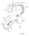
- the design of the chisel holder 10 can be closer in the Fig. 2 and 3 detect.
- the bit holder 10 has, following the attachment lug 11, a holding lug 15. This forms a rear support surface 14, which in the mounted state rests on a mating surface 43 of the base part 40.
- the retaining lug 15 has a cylindrical projection 16, in which formed as circumferential recesses wear marks are incorporated groove-like.
- the cylindrical projection 16 terminates with a support surface 18.
- the bit holder 20 is designed as a cylindrical through hole. It forms in the region of the support surface 18 a chisel introduction opening 24 and this averted a Austreibö Stamm 21st
- an opening 22 is incorporated in the holding lug 15 in the holding lug 15.
- the opening 22 opens the bit holder 20 to the centrifugal force side of the chisel holder 10. This can be clearly seen in the Fig. 1 seen.
- the bit holder 10 has a facing the base part 10 mounting side and this facing away from the centrifugal force side.
- a chisel 30 is inserted into the bit holder 20 of the chisel holder 10.
- the chisel 30 has a cylindrical chisel shaft 31 to which a chisel head 32 is integrally formed.
- a wear protection disc 35 is pushed in a known manner. This is circular and covers the support surface 18 of the chisel holder 10 completely.
- the chisel head 32 is supported centrally on the anti-wear washer 35.
- On the drill collar 31 a longitudinally slotted clamping sleeve 34 is pushed. This has holding elements 34.1, which engage in a circumferential groove of the drill collar 31 to form a rotary bearing.
- the bit 30 is thus freely rotatable in the clamping sleeve 34, but held captive axially.
- fine space material can reach the area of the bit receptacle 22. This finds its access in the area between the chisel head 32 and the anti-wear washer 35 or between the anti-wear washer 35 and the support surface 18 of the chisel holder 10. It passes through these paths in the chisel holder 20 and in the present case in the area between the drill collar 31 and the clamping sleeve 34. Due to the rotational movement and a small limited axial play of the drill collar 31 in the chip sleeve 34 creates a pumping effect. This promotes the space material in the direction of the free end of the drill collar 31. The space material often forms a sticky suspension when coolant, for example, water is used in the removal process.
- the scrap material becomes due to the pumping effect along the bit axis of the chisel insertion opening in the direction of the Austreibö réelle and thus promoted against the centrifugal force direction until it emerges from the intermediate region between the drill collar 31 and the clamping sleeve 34 at the free end of the drill collar 31.
- the centrifugal forces acting here on the accumulating space material now move this through the opening 22 from the bit receptacle 20.
- this area in terms of the direction of rotation of the roller in the "shadow", ie in the area of an open space of the bit 30 and the chisel holder 10 stands.
- a discharge in the direction of rotation or laterally is not possible due to the conditions at the milling drum, which is usually surrounded by a hood, since the path through the milled material or the surface to be removed is blocked here.
- the opening 22 extends a little way over the free end of the clamping sleeve 34 and thus also of the drill collar 31.
- the Austragungsrea can take place reliably. This would also succeed if the opening 22 terminates with the free end of the clamping sleeve 34 of the chisel shaft 31 or is arranged offset a distance.
- the opening 22 is in spatial communication with a rear-side recess 44 of the base part 40.
- the invention is of course not limited to the embodiment shown. It is also conceivable, for example, to use a clamping sleeve 34 which does not cover the entire cutter shank 31. The transport of the space material then takes place in the uncovered area between the inner wall of the bit holder 20 and the drill collar 31.
Landscapes
- Engineering & Computer Science (AREA)
- Mining & Mineral Resources (AREA)
- Mechanical Engineering (AREA)
- Life Sciences & Earth Sciences (AREA)
- General Life Sciences & Earth Sciences (AREA)
- Geochemistry & Mineralogy (AREA)
- Geology (AREA)
- Drilling And Exploitation, And Mining Machines And Methods (AREA)
- Road Repair (AREA)
- Processing Of Stones Or Stones Resemblance Materials (AREA)
- Earth Drilling (AREA)
- Gripping On Spindles (AREA)
- Grinding Of Cylindrical And Plane Surfaces (AREA)
- Grinding-Machine Dressing And Accessory Apparatuses (AREA)
- Auxiliary Devices For Machine Tools (AREA)
- Constituent Portions Of Griding Lathes, Driving, Sensing And Control (AREA)
- Percussive Tools And Related Accessories (AREA)
- Cutting Tools, Boring Holders, And Turrets (AREA)
- Food-Manufacturing Devices (AREA)
Description
- Die Erfindung betrifft eine Werkzeug-Haltevorrichtung mit einem Meißelhalter der in einem Halteansatz eine Meißelaufnahme zur Aufnahme eines darin auswechselbar aufnehmbaren Meißels aufweist, wobei die Meißelaufnahme bohrungsförmig ausgebildet ist und eine Meißeleinführungsöffnung aufweist, wobei der Meißelhalter eine Befestigungsseite mit einem Befestigungsansatz und der Befestigungsseite abgewandt eine Außenseite aufweist, und wobei während des Werkzeugeinsatzes Fliehkräfte in Richtung von der Befestigungseite zu der Außenseite wirken.
- Eine derartige Anordnung ist aus der
DE 43 22 401 C2 bekannt. Solche Werkzeug-Haltevorrichtungen werden beispielsweise bei Straßenfräsmaschinen, Bo-denstabilisierern, Bergbaumaschinen oder dergleichen eingesetzt. - Der Meißelhalter wird dabei üblicherweise über ein Basisteil an die Oberfläche einer Fräswalze angebaut. Der Meißelhalter dient zur auswechselbaren Aufnahme eines Meißels in der Meißelaufnahme. Dabei ist der Meißel mit Spiel in der Meißelaufnahme, meist unter Zuhilfenahme einer Spannhülse gehalten. Er ist dann in der Meißelaufnahme unverlierbar, jedoch um seine Mittellängsachse frei drehbar gehalten. Während des Werkzeugeinsatzes arbeitet der Meißel mit seiner Meißelspitze die zu bearbeitende Oberfläche, beispielsweise eine Straßenoberfläche ab. Dabei wird das Oberflächen-Material zerkleinert. Es entstehen grobe und feinere abgetragene Oberflächenteilchen. Diese werden aus dem Bereich der Fräswalze ausgetragen. Die feinen Partikel können in den Bereich der Meißelaufnahme vordringen. Sie setzen sich darin fest und behindern die freie Drehbarkeit des Meißels. Mitunter setzen sie die Meißel vollständig fest. Die verminderte Drehfähigkeit führt zu einem schnellen Verschleiß des Meißels. Wenn dieser nicht rechtzeitig erkannt wird, dann wird auch der Meißelhalter geschädigt. Dies bedingt dann eine kostenintensive Austauschmaßnahme.
- Weiterhin kann es sich als nachteilig erweisen, dass das in die Meißelaufnahme eingetragene feine Partikelmaterial das Auswechseln des Meißels aus der Meißelaufnahme behindert.
- Es ist Aufgabe der Erfindung, eine Werkzeug-Haltevorrichtung der eingangs erwähnten Art zu schaffen, bei der ein Festsetzen des Meißels infolge von in die Meißelaufnahme eingetragenen Abraummaterials verhindert ist.
- Diese Aufgabe wird dadurch gelöst, dass der Halteansatz eine Öffnung aufweist, die die Innenwandung der Meißelaufnahme durchdringt und eine räumliche Verbindung zur Umgebung schafft, und dass die Öffnung die Meißelaufnahme in Richtung zur Außenseite hin öffnet.
- Das in den Bereich der Meißelaufnahme eingetragene Abraummaterial wird von dem sich drehenden Meißel entlang der Meißellängsachse in die dem Meißelkopf abgewandte Richtung transportiert. Es entsteht somit eine "Pumpwirkung", die durch den periodischen Werkzeugeingriff unterstützt wird. Erfindungsgemäß weist nun der Meißelhalter eine Öffnung im Bereich der Meißelaufnahme auf. Diese ist fliehkraftseitig angeordnet. Wenn das Abraummaterial in die Meißelaufnahme eingefördert wird, gelangt es in den Bereich der Öffnung und kann wieder in die Umgebung entweichen. Auf diese Weise wird die freie Drehbarkeit des Meißels beibehalten.
- Gemäß einer möglichen Erfindungsvariante kann es vorgesehen sein, dass die Meißelaufnahme als Durchgangsbohrung ausgeführt ist und der Meißeleinführungsöffnung abgekehrt eine Austreiböffnung aufweist, und dass die Öffnung die Meißelaufnahme im Bereich der Austreiböffnung öffnet und sich ausgehend von der Austreiböffnung in Richtung der Meißeleinführöffnung erstreckt. Dem Anwender wird dann eine großzügige Zugänglichkeit zur Meißelaufnahme geboten, die eine schnelle und einfache Meißeldemontage zuläßt.
- Gemäß einer bevorzugten Ausgestaltungsvariante der Erfindung ist es vorgesehen, dass in die Meißelaufnahme ein Meißel mit einem Meißelschaft eingesetzt ist, und dass die Öffnung zumindest in dem dem Schaftende zugeordneten Bereich der Meißelaufnahme angeordnet ist. Bei dieser Anordnung macht man sich die Erkenntnis zunutze, dass das eingetragene Abraummaterial in Richtung der Meißelachse zum freien Ende des Meißelschaftes transportiert wird. Da nun die Öffnung in dem Bereich des Schaftendes des Meißels angeordnet ist, kann das sich hier ansammelnde Abraummaterial leicht in die Umgebung gelangen.
- Dabei kann die Öffnung bis dicht an das Schaftende, bis an das Schaftende oder das Schaftende teilweise übergreifend angeordnet sein.
- Die Öffnung läßt sich dann einfach fertigen, wenn vorgesehen ist, dass sie als schlitzförmige Ausnehmung ausgebildet ist, die zwei zueinander parallel in Richtung der Längsachse der Meißelaufnahme verlaufende Begrenzungsflächen aufweist, wobei die Begrenzungsflächen einen Abstand zueinander kleiner oder gleich dem Bohrungsdurchmesser der Meißelaufnahme aufweisen oder dass die Begrenzungsflächen im Winkel zueinander stehen und einen Winkel kleiner als 180° einschließen. Wenn vorgesehen ist, dass die Öffnung einen Teil der Innenwandung der Meißelaufnahme ausnimmt, der sich über weniger als 180° des Umfangs der bohrungsförmigen Meißelaufnahme erstreckt, dann wird die Meißelaufnahme in ihrer Stützfunktion für den eingesetzten Meißelschaft nur gering beeinträchtigt.
- Die Zugänglichkeit der Meißelaufnahme für ein Demontagewerkzeug wird dann weiter verbessert, wenn vorgesehen ist, dass der Meißelhalter an einem Basisteil befestigt ist, dass das Basisteil eine Ausnehmung aufweist, die Zugang für ein Demontagewerkzeug zu der Meißelaufnahme schafft, und dass die Ausnehmung in die Öffnung übergeht.
- Eine erfindungsgemäße Werkzeug-Haltevorrichtung kann dergestalt sein, dass dem Meißelhalter wenigstens eine Flüssigkeits-Sprühvorrichtung zugeordnet ist, die Flüssigkeit durch die Öffnung hindurch in die Meißelaufnahme einbringt. Die Flüssigkeit löst dann das sich in der Meißelaufnahme sammelnde Abraummaterial, so dass es leicht durch die Öffnung ausgetragen werden kann.
- Dies geschieht besonders effektiv dann, wenn vorgesehen ist, dass die Flüssigkeits-Sprühvorrichtung einen Flüssigkeitsstrahl auf das freie Ende des Meißelschaftes aufbringt.
- Die Erfindung wird im folgenden anhand eines in den Zeichnungen dargestellten Ausführungsbeispieles näher erläutert. Es zeigen:
- Fig. 1
- in Seitendarstellung und im Schnitt eine Werkzeug-Haltevorrichtung mit einem Meißel, einem Meißelhalter und einem Basisteil,
- Fig. 2
- den in
Fig. 1 gezeigten Meißelhalter in perspektivischer Rückansicht und - Fig. 3
- den Meißelhalter gemäß
Fig. 2 in verschiedenen Ansichten. - Die
Fig. 1 zeigt eine Werkzeug-Haltevorrichtung, die ein Basisteil 40 aufweist. Dieses kann mittels einer Befestigungsfläche 41 auf der gekrümmten Oberfläche einer Fräswalze (nicht gezeigt) befestigt beispielsweise angeschweißt werden. Das Basisteil 40 besitzt eine Steckaufnahme 42, in die ein Befestigungsansatz 11 eines Meißelhalters 10 eingesetzt ist. Der Befestigungsansatz 11 weißt eine Vertiefung 13 mit einer Druckfläche 13.1 auf. Die Druckfläche 13.1 wird von einer Druckschraube 46 beaufschlagt, die in ein Innengewinde des Basisteils 40 eingeschraubt ist. Die Druckschraube 46 ist durch eine Werkzeugdurchführung 45 hindurch für ein Schraubwerkzeug zugänglich. - Die Druckschraube 46 wirkt so auf die Druckfläche 13.1 ein, dass der Befestigungsansatz 11 in die Steckaufnahme 42 eingezogen wird. Dabei werden vorderseitige prismenförmig angeordnete Führungsflächen 12 gegen entsprechend ausgebildete Gegenflächen des Basisteils 40 angedrückt.
- Die Ausgestaltung des Meißelhalters 10 läßt sich näher in den
Fig. 2 und3 erkennen. Wie diese Dartstellungen zeigen, besitzt der Meißelhalter 10 im Anschluß an den Befestigungsansatz 11 einen Halteansatz 15. Dieser bildet eine rückwärtige Stützfläche 14, die im montierten Zustand auf einer Gegenfläche 43 des Basisteils 40 aufsitzt. Der Halteansatz 15 besitzt einen zylindrischen Ansatz 16, in den als umlaufende Vertiefungen ausgebildete Verschleißmarkierungen nutartig eingearbeitet sind. Der zylindrische Ansatz 16 schließt mit einer Stützfläche 18 ab. Durch die Stützfläche 18 hindurch ist eine Meißelaufnahme 20 in den Halteansatz 15 eingebracht. Die Meißelaufnahme 20 ist als zylindrische Durchgangsbohrung ausgeführt. Sie bildet im Bereich der Stützfläche 18 eine Meißeleinführungsöffnung 24 und dieser abgekehrt eine Austreiböffnung 21. - In den Halteansatz 15 ist eine Öffnung 22 eingearbeitet. Diese schafft eine räumliche Verbindung zwischen der Umgebung und der Meißelaufnahme 20. Dabei öffnet die Öffnung 22 die Meißelaufnahme 20 zur Fliehkraftseite des Meißelhalters 10 hin. Dies läßt sich deutlich aus der
Fig. 1 ersehen. Der Meißelhalter 10 besitzt eine zum Basisteil 10 gewandte Befestigungsseite und diesem abgewandt die Fliehkraftseite. - Während des Werkzeugeinsatzes wird die Fräswalze, und mit ihr die Werkzeug-Haltevorrichtung in Richtung des in
Fig. 1 angedeuteten Pfeils "A" gedreht. - Dabei entstehen Fliehkräfte, die radial nach außen gerichtet in Richtung der Fliehkraftseite des Meißelhalters 10 wirken.
- Wie die
Fig. 1 weiter erkennen läßt, ist in die Meißelaufnahme 20 des Meißelhalters 10 ein Meißel 30 eingesteckt. Der Meißel 30 besitzt einen zylindrischen Meißelschaft 31 an den einteilig ein Meißelkopf 32 angeformt ist. Auf den Meißelschaft 31 ist in bekannter Weise eine Verschleißschutz-Scheibe 35 aufgeschoben. Diese ist kreisförmig ausgebildet und deckt die Stützfläche 18 des Meißelhalters 10 vollständig ab. Auf der der Stützfläche 18 abgekehrten Seite stützt sich der Meißelkopf 32 zentrisch auf der Verschleißschutz-Scheibe 35 ab. Auf den Meißelschaft 31 ist eine längsgeschlitzte Spannhülse 34 aufgeschoben. Diese besitzt Halteelemente 34.1, die in eine umlaufende Nut des Meißelschaftes 31 zur Bildung einer Drehlagerung eingreifen. Der Meißel 30 ist damit in der Spannhülse 34 frei drehbar, jedoch axial unverlierbar gehalten. - Beim Spanabtrag kann feines Abraummaterial in den Bereich der Meißelaufnahme 22 gelangen. Dieses findet seinen Zugang im Bereich zwischen dem Meißelkopf 32 und der Verschleißschutz-Scheibe 35 beziehungsweise zwischen der Verschleißschutz-Scheibe 35 und der Stützfläche 18 des Meißelhalters 10. Es gelangt über diese Wege in die Meißelaufnahme 20 und im vorliegenden Fall in den Bereich zwischen dem Meißelschaft 31 und der Spannhülse 34. Infolge der Drehbewegung und eines gering begrenzten Axialspiels des Meißelschaftes 31 in der Spanhülse 34 entsteht ein Pumpeffekt. Dieser fördert das Abraummaterial in Richtung zum freien Ende des Meißelschaftes 31. Das Abraummaterial bildet häufig dann eine auch klebrige Suspension, wenn beim Abtragungsprozeß Kühlmittel, beispielsweise Wasser eingesetzt wird. Das Abraummaterial wird infolge des Pumpeffektes entlang der Meißelachse von der Meißeleinführungsöffnung in Richtung der Austreiböffnung und damit entgegen der Fliehkraftrichtung gefördert, bis es am freien Ende des Meißelschaftes 31 aus dem Zwischenbereich zwischen dem Meißelschaft 31 und der Spannhülse 34 austritt. Die hier auf das sich ansammelnde Abraummaterial einwirkenden Fliehkräfte bewegen nun dieses durch die Öffnung 22 hindurch aus der Meißelaufnahme 20.
- Hier macht man sich die Besonderheit zunutze, dass dieser Bereich in Bezug auf die Drehrichtung der Walze im "Schatten", also im Bereich einer Freifläche des Meißels 30 und des Meißelhalters 10 steht. Ein Austrag in Drehrichtung oder seitlich ist durch die Gegebenheiten an der üblicherweise von einer Haube umgebenen Fräswalze nicht möglich da hier der Weg durch das Fräsgut bzw. die abzutragende Oberfläche versperrt ist.
- Wie die
Fig. 1 deutlich zeigt, übergreift die Öffnung 22 ein Stück weit das freie Ende der Spannhülse 34 und damit auch des Meißelschaftes 31. Damit kann der Austragungsprozess zuverlässig stattfinden. Dies würde auch gelingen, wenn die Öffnung 22 mit dem freien Ende der Spannhülse 34 des Meißelschaftes 31 abschließt oder ein Stück weit versetzt angeordnet ist. - Die Öffnung 22 steht in räumlicher Verbindung mit einer rückseitigen Ausnehmung 44 des Basisteils 40.
- Damit wird ein großzügiger Zugang zum freien Ende des Meißelschaftes 31 geschaffen. Dies erleichtert das Ansetzen eines Demontagewerkzeuges auf das einsehbare Ende des Meißelschaftes 31. Dieses kann dann bequem durch die Austreiböffnung 43 in die Meißelaufnahme 20 geschoben werden.
- Die Erfindung ist selbstverständlich nicht auf das gezeigte Ausführungsbeispiel beschränkt. Es ist beispielsweise auch denkbar eine Spannhülse 34 zu verwenden, die nicht den gesamte Meißelschaft 31 überdeckt. Der Transport des Abraummaterials findet dann im nicht überdeckten Bereich zwischen der Innenwandung der Meißelaufnahme 20 und dem Meißelschaft 31 statt.
Claims (8)
- Werkzeug-Haltevorrichtung mit einem Meißelhalter (10), der in einem Halteansatz (15) eine Meißelaufnahme (20) zur Aufnahme eines darin auswechselbar aufnehmbaren Meißels (30) aufweist, wobei die Meißelaufnahme (20) bohrungsförmig ausgebildet ist und eine Meißeleinführungsöffnung (24) aufweist, wobei der Meißelhalter (10) eine Befestigungsseite mit einem Befestigungsansatz (11) und der Befestigungsseite abgewandt eine Außenseite aufweist, und wobei während des Werkzeug- einsatzes Fliehkräfte in Richtung von der Befestigungseite zu der Außenseite wirken,
dadurch gekennzeichnet,
dass der Halteansatz (15) eine Öffnung (22) aufweist, die die Innenwandung der Meißelaufnahme (20) durchdringt und eine räumliche Verbindung zur Umgebung schafft, und
dass die Öffnung (22) die Meißelaufnahme (20) in Richtung zur Außenseite hin öffnet. - Werkzeug-Haltevorrichtung nach Anspruch 1,
dadurch gekennzeichnet,
dass die Meißelaufnahme (20) als Durchgangsbohrung ausgeführt ist und der Meißeleinführungsöffnung (24) abgekehrt eine Austreiböffnung (21) aufweist, und
dass die Öffnung (22) die Meißelaufnahme (20) im Bereich der Austreiböffnung (21) öffnet und sich ausgehend von der Austreiböffnung (21) in Richtung der Meißeleinführöffnung (24) erstreckt. - Werkzeug-Haltevorrichtung nach Anspruch 1 oder 2,
dadurch gekennzeichnet,
dass in die Meißelaufnahme (20) ein Meißel (30) mit einem Meißelschaft (31) eingesetzt ist, und
dass die Öffnung (22) zumindest in dem dem Schaftende zugeordneten Bereich der Meißelaufnahme (20) angeordnet ist. - Werkzeug-Haltevorrichtung nach einem der Ansprüche 1 bis 3,
dadurch gekennzeichnet,
dass die Öffnung (22) als schlitzförmige Ausnehmung ausgebildet ist, die zwei zueinander parallel in Richtung der Längsachse der Meißelaufnahme (20) verlaufende Begrenzungsflächen (23) aufweist,
wobei die Begrenzungsflächen (23) einen Abstand zueinander kleiner oder gleich dem Bohrungsdurchmesser der Meißelaufnahme (20) aufweisen oder dass die Begrenzungsflächen (23) im Winkel zueinander stehen und einen Winkel kleiner als 180° einschließen. - Werkzeug-Haltevorrichtung nach einem der Ansprüche 1 bis 4,
dadurch gekennzeichnet,
dass die Öffnung (22) einen Teil der Innenwandung der Meißelaufnahme ausnimmt, der sich über weniger als 180° des Umfangs der bohrungsförmigen Meißelaufnahme (20) erstreckt. - Werkzeug-Haltevorrichtung nach einem der Ansprüche 1 bis 5,
dadurch gekennzeichnet,
dass der Meißelhalter (10) an einem Basisteil (40) befestigt ist,
dass das Basisteil (40) eine Ausnehmung (44) aufweist, die Zugang für ein Demontagewerkzeug zu der Austreiböffnung (21) der Meißelaufnahme (20) schafft, und
dass die Ausnehmung (44) in die Öffnung (22) übergeht. - Werkzeug-Haltevorrichtung nach einem der Ansprüche 1 bis 6,
dadurch gekennzeichnet,
dass dem Meißelhalter (10) wenigstens eine Flüssigkeits-Sprühvorrichtung zugeordnet ist, die Flüssigkeit durch die Öffnung (22) hindurch in die Meißelaufnahme (20) einbringt. - Werkzeug-Haltevorrichtung nach Anspruch 7,
dadurch gekennzeichnet,
dass die Flüssigkeits-Sprühvorrichtung einen Flüssigkeitsstrahl auf das freie Ende des Meißelschaftes (31) aufbringt.
Priority Applications (1)
| Application Number | Priority Date | Filing Date | Title |
|---|---|---|---|
| PL05732397T PL1761682T3 (pl) | 2004-06-24 | 2005-04-16 | Przyrząd do mocowania narzędzia |
Applications Claiming Priority (2)
| Application Number | Priority Date | Filing Date | Title |
|---|---|---|---|
| DE102004030691A DE102004030691B4 (de) | 2004-06-24 | 2004-06-24 | Werkzeug-Haltevorrichtung |
| PCT/EP2005/004057 WO2006000270A1 (de) | 2004-06-24 | 2005-04-16 | Werkzeug-haltevorrichtung |
Publications (2)
| Publication Number | Publication Date |
|---|---|
| EP1761682A1 EP1761682A1 (de) | 2007-03-14 |
| EP1761682B1 true EP1761682B1 (de) | 2008-03-19 |
Family
ID=34964635
Family Applications (1)
| Application Number | Title | Priority Date | Filing Date |
|---|---|---|---|
| EP05732397A Expired - Lifetime EP1761682B1 (de) | 2004-06-24 | 2005-04-16 | Werkzeug-haltevorrichtung |
Country Status (12)
| Country | Link |
|---|---|
| US (2) | US7597402B2 (de) |
| EP (1) | EP1761682B1 (de) |
| JP (1) | JP4696112B2 (de) |
| CN (1) | CN1942655B (de) |
| AT (1) | ATE389780T1 (de) |
| AU (1) | AU2005256341B2 (de) |
| BR (1) | BRPI0512409B1 (de) |
| DE (2) | DE102004030691B4 (de) |
| ES (1) | ES2303241T3 (de) |
| PL (1) | PL1761682T3 (de) |
| RU (1) | RU2334105C2 (de) |
| WO (1) | WO2006000270A1 (de) |
Cited By (1)
| Publication number | Priority date | Publication date | Assignee | Title |
|---|---|---|---|---|
| EP2336489A3 (de) * | 2009-12-17 | 2016-06-29 | Wirtgen GmbH | Meißelhalter und Basisteil zur Aufnahme eines Meißelhalters |
Families Citing this family (39)
| Publication number | Priority date | Publication date | Assignee | Title |
|---|---|---|---|---|
| DE102004057302B4 (de) * | 2004-11-26 | 2011-01-13 | Wirtgen Gmbh | Meißelhalter |
| EP2048323B1 (de) | 2007-10-11 | 2010-07-28 | Everpads Co., Ltd. | Werkzeughaltevorrichtung |
| DE102008045825B3 (de) * | 2008-09-05 | 2010-05-27 | Wirtgen Gmbh | Meißelhalter für eine Schrämmaschine, Straßenfräse, Suface-Miner oder dergleichen |
| DE102008052389A1 (de) * | 2008-10-16 | 2010-04-22 | Betek Bergbau- Und Hartmetalltechnik Karl-Heinz Simon Gmbh & Co. Kg | Meißel |
| DE102009049780B4 (de) * | 2009-10-19 | 2016-02-18 | Betek Gmbh & Co. Kg | Meißel, insbesondere Rundschaftmeißel |
| DE102009059188A1 (de) * | 2009-12-17 | 2011-06-22 | Wirtgen GmbH, 53578 | Meißelhalter und Basisteil |
| US9028009B2 (en) | 2010-01-20 | 2015-05-12 | Element Six Gmbh | Pick tool and method for making same |
| US8322795B2 (en) * | 2010-01-22 | 2012-12-04 | Joy Mm Delaware, Inc. | Miner cutting bit holding apparatus |
| CN102200012A (zh) * | 2010-03-26 | 2011-09-28 | 钴碳化钨硬质合金公司 | 用于可旋转切削刀头的夹持件 |
| DE102010044649A1 (de) * | 2010-09-07 | 2012-03-08 | Bomag Gmbh | Wechselhaltersystem für einen Meißel |
| DE102010051048A1 (de) * | 2010-11-11 | 2012-05-16 | Bomag Gmbh | Wechselhaltersystem für einen Meißel |
| TWI480447B (zh) | 2010-12-03 | 2015-04-11 | Wirtgen Gmbh | Turret (b) |
| RU2567256C2 (ru) * | 2010-12-03 | 2015-11-10 | Виртген Гмбх | Резцедержатель и система резцедержателя с резцедержателем и корпусом |
| DE102010061019A1 (de) | 2010-12-03 | 2012-06-06 | Betek Gmbh & Co. Kg | Meißelhalter und Werkzeugunterteil für einen Meißelhalter |
| KR101788266B1 (ko) | 2010-12-03 | 2017-10-19 | 비르트겐 게엠베하 | 치즐 홀더 |
| US9163502B2 (en) | 2010-12-03 | 2015-10-20 | Wirtgen Gmbh | Chisel holder, and chisel holder system comprising a chisel holder and a base part |
| USD667855S1 (en) | 2011-04-11 | 2012-09-25 | Betek Gmbh & Co. Kg | Base for a chisel holder |
| USD667856S1 (en) | 2011-04-11 | 2012-09-25 | Betek Gmbh & Co. Kg | Chisel holder |
| DE102011051525A1 (de) | 2011-07-04 | 2013-01-10 | Wirtgen Gmbh | Meißelhalter für eine Bodenbearbeitungsmaschine |
| USD671578S1 (en) | 2011-07-04 | 2012-11-27 | Wirtgen Gmbh | Chisel holder |
| GB201113591D0 (en) * | 2011-08-08 | 2011-09-21 | Hydra Mining Tools Internat Ltd | Mineral cutter tool |
| USD677285S1 (en) * | 2011-11-23 | 2013-03-05 | Wirtgen Gmbh | Chisel holder bar |
| USD669505S1 (en) * | 2011-11-23 | 2012-10-23 | Wirtgen Gmbh | Chisel holder bar |
| US8911024B2 (en) * | 2012-07-31 | 2014-12-16 | Caterpillar Paving Products Inc. | Milling drum tool holder |
| CN103669186B (zh) * | 2012-09-18 | 2015-12-16 | 常州市瑞泰工程机械有限公司 | 铣刨齿 |
| USD772315S1 (en) * | 2013-04-11 | 2016-11-22 | Betek Gmbh & Co. Kg | Chisel |
| DE102013110676A1 (de) | 2013-09-26 | 2015-03-26 | Betek Gmbh & Co. Kg | Meißel |
| DE102013110680A1 (de) | 2013-09-26 | 2015-03-26 | Betek Gmbh & Co. Kg | Meißelhalter und Kombination eines Meißelhalters mit einem Meißel |
| US11339656B1 (en) * | 2014-02-26 | 2022-05-24 | The Sollami Company | Rear of base block |
| CN104452559B (zh) * | 2014-10-23 | 2017-01-11 | 湖南三一路面机械有限公司 | 一种铣刨机及其铣刨鼓、快换刀座系统 |
| CN104594169A (zh) * | 2015-01-27 | 2015-05-06 | 浙江澳德耐磨零部件有限公司 | 一种路面铣刨机的组合刀座 |
| CN106032659B (zh) * | 2015-03-09 | 2018-04-06 | 徐工集团工程机械股份有限公司 | 刀齿夹持装置以及铣刨机 |
| CN106149535B (zh) * | 2015-03-27 | 2019-04-12 | 永沛得股份有限公司 | 刀具夹持器 |
| USD808449S1 (en) | 2016-03-11 | 2018-01-23 | Wirtgen Gmbh | Chisel |
| DE102016108808A1 (de) | 2016-05-12 | 2017-11-16 | Betek Gmbh & Co. Kg | Meißel mit einem Stützelement mit einem Zentrieransatz |
| USD844684S1 (en) * | 2017-02-22 | 2019-04-02 | American Carbide Tools Innovations, LLC | Rotatable cutting bit |
| DE202017107805U1 (de) * | 2017-09-21 | 2019-01-08 | Betek Gmbh & Co. Kg | Fixationselement |
| AU201816544S (en) | 2018-08-01 | 2018-11-27 | Betek Gmbh & Co Kg | A chisel |
| RU189511U1 (ru) * | 2018-12-28 | 2019-05-24 | Общество с ограниченной ответственностью "СиПиСи ИмпЭкс" | Укупорочное устройство с контейнером |
Family Cites Families (23)
| Publication number | Priority date | Publication date | Assignee | Title |
|---|---|---|---|---|
| IT245488Y1 (it) | 1998-11-10 | 2002-03-20 | Bitelli Spa | Portautensile per tamburo fresante di macchine scarificatrici. |
| JPS5020902A (de) * | 1973-06-26 | 1975-03-05 | ||
| AT354385B (de) | 1978-06-15 | 1980-01-10 | Voest Ag | Meisselanordnung fuer ein schraemwerkzeug |
| US4337980A (en) * | 1979-05-21 | 1982-07-06 | The Cincinnati Mine Machinery Company | Wedge arrangements and related means for mounting means, base members, and bits, and combinations thereof, for mining, road working, or earth moving machinery |
| US4684176A (en) * | 1984-05-16 | 1987-08-04 | Den Besten Leroy E | Cutter bit device |
| DE3441949C1 (de) * | 1984-11-16 | 1986-04-24 | Friedrich Wilhelm Paurat | Vorrichtung für die Halterung der Schneidmeißel sowie für die Steuerung der Bedüsungsmittelzufuhr bei einem Schneidkopf für eine Streckenvortriebsmaschine |
| DE8520046U1 (de) * | 1985-07-11 | 1985-08-22 | Jädke, Jürgen, 4320 Hattingen | Meißelhalter für einen Schaftmeißel |
| JPS62253897A (ja) * | 1986-04-23 | 1987-11-05 | 日本鉱機株式会社 | 掘削機のカツテイングヘツド装置 |
| DE3701905C1 (de) | 1987-01-23 | 1988-09-15 | Betek Bergbau & Hartmetall | Befestigung eines Rundschaftmeissels |
| JPS63126495U (de) * | 1987-02-12 | 1988-08-18 | ||
| US4915455A (en) * | 1988-11-09 | 1990-04-10 | Joy Technologies Inc. | Miner cutting bit holding apparatus |
| JPH0520902A (ja) | 1991-07-15 | 1993-01-29 | Koito Mfg Co Ltd | 車輌用灯具 |
| DE4322401C2 (de) * | 1993-07-06 | 1996-06-20 | Betek Bergbau & Hartmetall | Befestigung eines Schrämwerkzeugs an einem Schrämkörper |
| GB9400114D0 (en) | 1994-01-05 | 1994-03-02 | Minnovation Ltd | Mineral pick box |
| US5415462A (en) * | 1994-04-14 | 1995-05-16 | Kennametal Inc. | Rotatable cutting bit and bit holder |
| US5529384A (en) * | 1994-08-25 | 1996-06-25 | Rogers Tool Works, Inc. | Bit holder block and cutter bit therefor |
| ATE204625T1 (de) | 1995-10-31 | 2001-09-15 | Bitelli Spa | Einsatz-element zur aufnahme wenigstens eines fräswerkzeuges, das auf frästrommeln von arbeitsmaschinen zur entfernung von böden anzubringen ist |
| GB9717830D0 (en) * | 1997-08-22 | 1997-10-29 | Minnovation Ltd | Water spray nozzle etc for mining |
| UA73489C2 (en) * | 1998-12-08 | 2005-08-15 | Genisis Mining Technologies Pr | Cutting arrangement and sleeve for it |
| IT1308135B1 (it) | 1999-03-03 | 2001-11-29 | Bitelli Spa | Portautensile perfezionato per tamburi fresanti di macchine operatriciper la rimozione di suoli. |
| IT1308147B1 (it) | 1999-04-12 | 2001-11-29 | Bitelli Spa | Elemento attivo per tamburi fresanti dimacchine operatrici per la rimozione di suoli, provvisto di |
| ITVI20010100A1 (it) * | 2001-05-08 | 2002-11-08 | Bitelli Spa | Base di supporto per portautensili di tamburi fresanti per macchine scarificatrici e calotta di protezione per detta base di supporto |
| JP5020902B2 (ja) | 2008-07-28 | 2012-09-05 | 株式会社アネモス | 溶存酸素低減方法及び装置 |
-
2004
- 2004-06-24 DE DE102004030691A patent/DE102004030691B4/de not_active Expired - Fee Related
-
2005
- 2005-04-16 CN CN2005800118290A patent/CN1942655B/zh not_active Expired - Lifetime
- 2005-04-16 PL PL05732397T patent/PL1761682T3/pl unknown
- 2005-04-16 DE DE502005003350T patent/DE502005003350D1/de not_active Expired - Lifetime
- 2005-04-16 AT AT05732397T patent/ATE389780T1/de active
- 2005-04-16 JP JP2007517002A patent/JP4696112B2/ja not_active Expired - Fee Related
- 2005-04-16 ES ES05732397T patent/ES2303241T3/es not_active Expired - Lifetime
- 2005-04-16 EP EP05732397A patent/EP1761682B1/de not_active Expired - Lifetime
- 2005-04-16 WO PCT/EP2005/004057 patent/WO2006000270A1/de not_active Ceased
- 2005-04-16 AU AU2005256341A patent/AU2005256341B2/en not_active Ceased
- 2005-04-16 US US10/586,428 patent/US7597402B2/en not_active Ceased
- 2005-04-16 US US13/253,540 patent/USRE45540E1/en not_active Expired - Lifetime
- 2005-04-16 BR BRPI0512409A patent/BRPI0512409B1/pt not_active IP Right Cessation
- 2005-04-16 RU RU2006137077/03A patent/RU2334105C2/ru not_active IP Right Cessation
Cited By (1)
| Publication number | Priority date | Publication date | Assignee | Title |
|---|---|---|---|---|
| EP2336489A3 (de) * | 2009-12-17 | 2016-06-29 | Wirtgen GmbH | Meißelhalter und Basisteil zur Aufnahme eines Meißelhalters |
Also Published As
| Publication number | Publication date |
|---|---|
| CN1942655A (zh) | 2007-04-04 |
| DE102004030691B4 (de) | 2008-12-18 |
| BRPI0512409A (pt) | 2008-03-04 |
| BRPI0512409B1 (pt) | 2015-12-08 |
| JP4696112B2 (ja) | 2011-06-08 |
| USRE45540E1 (en) | 2015-06-02 |
| RU2006137077A (ru) | 2008-04-27 |
| ATE389780T1 (de) | 2008-04-15 |
| EP1761682A1 (de) | 2007-03-14 |
| AU2005256341A1 (en) | 2006-01-05 |
| CN1942655B (zh) | 2010-08-18 |
| WO2006000270A1 (de) | 2006-01-05 |
| PL1761682T3 (pl) | 2008-08-29 |
| AU2005256341B2 (en) | 2009-12-24 |
| JP2008503669A (ja) | 2008-02-07 |
| US20080223744A1 (en) | 2008-09-18 |
| US7597402B2 (en) | 2009-10-06 |
| DE502005003350D1 (de) | 2008-04-30 |
| DE102004030691A1 (de) | 2006-01-19 |
| ES2303241T3 (es) | 2008-08-01 |
| RU2334105C2 (ru) | 2008-09-20 |
Similar Documents
| Publication | Publication Date | Title |
|---|---|---|
| DE102004030691B4 (de) | Werkzeug-Haltevorrichtung | |
| DE102012100181B4 (de) | Meissel-Halterungssystem mit einer Öffnung zur Entnahme von zerbrochenen Meisseln | |
| DE19839440C2 (de) | Meißelhalter für ein Schrämwerkzeug | |
| DE102004057302B4 (de) | Meißelhalter | |
| EP2160274B1 (de) | Schaftmeissel | |
| DE19781717B4 (de) | Halterung für eine Schrämpicke | |
| EP2915642B1 (de) | Baumaschine | |
| DE10357810B4 (de) | Drehbarer Einsatz mit einer elastischen, spielbehafteten Sicherungshülse | |
| DE69423099T2 (de) | Ausnehmung zum lösen von meisseln mit flansch | |
| DE3439491C2 (de) | ||
| DE102013220884B4 (de) | Modulares Trägerwerkzeug sowie Werkzeugkopf | |
| DE60207371T2 (de) | Stumpfvermahlungsgerät | |
| DE3875534T2 (de) | Schneidwerkzeug fuer metall. | |
| EP2318656A1 (de) | Meisselhalter mit schweissung als verschleissschutzelement | |
| DE112010001584B4 (de) | Aus einem drehbaren Schneidwerkzeug, einem Werkzeughalter und einer Basis bestehendeAnordnung | |
| DE19857451A1 (de) | Schneid- oder Brechwerkzeug sowie Schneideinsatz für dieses | |
| EP2820243B1 (de) | Meisselhalter | |
| DE112010001564T5 (de) | Halteanordnung für eine Schneidspitze | |
| DE102005042663A1 (de) | Nicht drehbarer Verschleißring und Rückhaltemuffe für ein drehbares Werkzeug | |
| DE19810192A1 (de) | Bohrwerkzeug | |
| DE2409629B2 (de) | Schräm- bzw. BohrmeiBelanordnung für bergmännische Gewinnungsmaschinen | |
| DE102010052845A1 (de) | Rotierendes Schneidwerkzeug und Führungseinsatz hierfür | |
| DE10154434B4 (de) | Anschlagvorrichtung | |
| DE102011051584A1 (de) | Verfahren zur Lagerung eines Meißels sowie zugehörige Vorrichtung | |
| DE29703689U1 (de) | Haubenförmige Auffangeinrichtung für eine Bohrkrone o.dgl. zum Auffangen von Bohrmehl |
Legal Events
| Date | Code | Title | Description |
|---|---|---|---|
| PUAI | Public reference made under article 153(3) epc to a published international application that has entered the european phase |
Free format text: ORIGINAL CODE: 0009012 |
|
| 17P | Request for examination filed |
Effective date: 20070124 |
|
| AK | Designated contracting states |
Kind code of ref document: A1 Designated state(s): AT BE BG CH CY CZ DE DK EE ES FI FR GB GR HU IE IS IT LI LT LU MC NL PL PT RO SE SI SK TR |
|
| DAX | Request for extension of the european patent (deleted) | ||
| GRAP | Despatch of communication of intention to grant a patent |
Free format text: ORIGINAL CODE: EPIDOSNIGR1 |
|
| GRAS | Grant fee paid |
Free format text: ORIGINAL CODE: EPIDOSNIGR3 |
|
| GRAA | (expected) grant |
Free format text: ORIGINAL CODE: 0009210 |
|
| AK | Designated contracting states |
Kind code of ref document: B1 Designated state(s): AT BE BG CH CY CZ DE DK EE ES FI FR GB GR HU IE IS IT LI LT LU MC NL PL PT RO SE SI SK TR |
|
| REG | Reference to a national code |
Ref country code: GB Ref legal event code: FG4D Free format text: NOT ENGLISH |
|
| REG | Reference to a national code |
Ref country code: CH Ref legal event code: EP |
|
| REF | Corresponds to: |
Ref document number: 502005003350 Country of ref document: DE Date of ref document: 20080430 Kind code of ref document: P |
|
| REG | Reference to a national code |
Ref country code: IE Ref legal event code: FG4D Free format text: LANGUAGE OF EP DOCUMENT: GERMAN |
|
| PG25 | Lapsed in a contracting state [announced via postgrant information from national office to epo] |
Ref country code: LT Free format text: LAPSE BECAUSE OF FAILURE TO SUBMIT A TRANSLATION OF THE DESCRIPTION OR TO PAY THE FEE WITHIN THE PRESCRIBED TIME-LIMIT Effective date: 20080319 Ref country code: FI Free format text: LAPSE BECAUSE OF FAILURE TO SUBMIT A TRANSLATION OF THE DESCRIPTION OR TO PAY THE FEE WITHIN THE PRESCRIBED TIME-LIMIT Effective date: 20080319 |
|
| REG | Reference to a national code |
Ref country code: ES Ref legal event code: FG2A Ref document number: 2303241 Country of ref document: ES Kind code of ref document: T3 |
|
| REG | Reference to a national code |
Ref country code: PL Ref legal event code: T3 |
|
| PG25 | Lapsed in a contracting state [announced via postgrant information from national office to epo] |
Ref country code: SI Free format text: LAPSE BECAUSE OF FAILURE TO SUBMIT A TRANSLATION OF THE DESCRIPTION OR TO PAY THE FEE WITHIN THE PRESCRIBED TIME-LIMIT Effective date: 20080319 |
|
| REG | Reference to a national code |
Ref country code: CH Ref legal event code: NV Representative=s name: SCHNEIDER FELDMANN AG PATENT- UND MARKENANWAELTE |
|
| REG | Reference to a national code |
Ref country code: IE Ref legal event code: FD4D |
|
| PG25 | Lapsed in a contracting state [announced via postgrant information from national office to epo] |
Ref country code: PT Free format text: LAPSE BECAUSE OF FAILURE TO SUBMIT A TRANSLATION OF THE DESCRIPTION OR TO PAY THE FEE WITHIN THE PRESCRIBED TIME-LIMIT Effective date: 20080827 Ref country code: SK Free format text: LAPSE BECAUSE OF FAILURE TO SUBMIT A TRANSLATION OF THE DESCRIPTION OR TO PAY THE FEE WITHIN THE PRESCRIBED TIME-LIMIT Effective date: 20080319 |
|
| ET | Fr: translation filed | ||
| PG25 | Lapsed in a contracting state [announced via postgrant information from national office to epo] |
Ref country code: MC Free format text: LAPSE BECAUSE OF NON-PAYMENT OF DUE FEES Effective date: 20080430 Ref country code: RO Free format text: LAPSE BECAUSE OF FAILURE TO SUBMIT A TRANSLATION OF THE DESCRIPTION OR TO PAY THE FEE WITHIN THE PRESCRIBED TIME-LIMIT Effective date: 20080319 |
|
| PG25 | Lapsed in a contracting state [announced via postgrant information from national office to epo] |
Ref country code: IS Free format text: LAPSE BECAUSE OF FAILURE TO SUBMIT A TRANSLATION OF THE DESCRIPTION OR TO PAY THE FEE WITHIN THE PRESCRIBED TIME-LIMIT Effective date: 20080719 |
|
| PLBE | No opposition filed within time limit |
Free format text: ORIGINAL CODE: 0009261 |
|
| STAA | Information on the status of an ep patent application or granted ep patent |
Free format text: STATUS: NO OPPOSITION FILED WITHIN TIME LIMIT |
|
| PG25 | Lapsed in a contracting state [announced via postgrant information from national office to epo] |
Ref country code: IE Free format text: LAPSE BECAUSE OF FAILURE TO SUBMIT A TRANSLATION OF THE DESCRIPTION OR TO PAY THE FEE WITHIN THE PRESCRIBED TIME-LIMIT Effective date: 20080319 Ref country code: EE Free format text: LAPSE BECAUSE OF FAILURE TO SUBMIT A TRANSLATION OF THE DESCRIPTION OR TO PAY THE FEE WITHIN THE PRESCRIBED TIME-LIMIT Effective date: 20080319 Ref country code: DK Free format text: LAPSE BECAUSE OF FAILURE TO SUBMIT A TRANSLATION OF THE DESCRIPTION OR TO PAY THE FEE WITHIN THE PRESCRIBED TIME-LIMIT Effective date: 20080319 |
|
| 26N | No opposition filed |
Effective date: 20081222 |
|
| PG25 | Lapsed in a contracting state [announced via postgrant information from national office to epo] |
Ref country code: BG Free format text: LAPSE BECAUSE OF FAILURE TO SUBMIT A TRANSLATION OF THE DESCRIPTION OR TO PAY THE FEE WITHIN THE PRESCRIBED TIME-LIMIT Effective date: 20080619 |
|
| PG25 | Lapsed in a contracting state [announced via postgrant information from national office to epo] |
Ref country code: CY Free format text: LAPSE BECAUSE OF FAILURE TO SUBMIT A TRANSLATION OF THE DESCRIPTION OR TO PAY THE FEE WITHIN THE PRESCRIBED TIME-LIMIT Effective date: 20080319 |
|
| PG25 | Lapsed in a contracting state [announced via postgrant information from national office to epo] |
Ref country code: LU Free format text: LAPSE BECAUSE OF NON-PAYMENT OF DUE FEES Effective date: 20080416 Ref country code: HU Free format text: LAPSE BECAUSE OF FAILURE TO SUBMIT A TRANSLATION OF THE DESCRIPTION OR TO PAY THE FEE WITHIN THE PRESCRIBED TIME-LIMIT Effective date: 20080920 |
|
| PG25 | Lapsed in a contracting state [announced via postgrant information from national office to epo] |
Ref country code: GR Free format text: LAPSE BECAUSE OF FAILURE TO SUBMIT A TRANSLATION OF THE DESCRIPTION OR TO PAY THE FEE WITHIN THE PRESCRIBED TIME-LIMIT Effective date: 20080620 |
|
| REG | Reference to a national code |
Ref country code: FR Ref legal event code: PLFP Year of fee payment: 12 |
|
| REG | Reference to a national code |
Ref country code: FR Ref legal event code: PLFP Year of fee payment: 13 |
|
| REG | Reference to a national code |
Ref country code: FR Ref legal event code: PLFP Year of fee payment: 14 |
|
| PGFP | Annual fee paid to national office [announced via postgrant information from national office to epo] |
Ref country code: PL Payment date: 20200326 Year of fee payment: 16 |
|
| PGFP | Annual fee paid to national office [announced via postgrant information from national office to epo] |
Ref country code: CH Payment date: 20200420 Year of fee payment: 16 Ref country code: FR Payment date: 20200420 Year of fee payment: 16 Ref country code: TR Payment date: 20200415 Year of fee payment: 16 Ref country code: CZ Payment date: 20200415 Year of fee payment: 16 Ref country code: NL Payment date: 20200427 Year of fee payment: 16 Ref country code: ES Payment date: 20200629 Year of fee payment: 16 |
|
| PGFP | Annual fee paid to national office [announced via postgrant information from national office to epo] |
Ref country code: IT Payment date: 20200428 Year of fee payment: 16 Ref country code: SE Payment date: 20200427 Year of fee payment: 16 Ref country code: GB Payment date: 20200427 Year of fee payment: 16 Ref country code: BE Payment date: 20200427 Year of fee payment: 16 |
|
| PGFP | Annual fee paid to national office [announced via postgrant information from national office to epo] |
Ref country code: AT Payment date: 20200421 Year of fee payment: 16 |
|
| REG | Reference to a national code |
Ref country code: CH Ref legal event code: PFA Owner name: WIRTGEN GMBH, DE Free format text: FORMER OWNER: WIRTGEN GMBH, DE |
|
| REG | Reference to a national code |
Ref country code: SE Ref legal event code: EUG |
|
| REG | Reference to a national code |
Ref country code: NL Ref legal event code: MM Effective date: 20210501 |
|
| REG | Reference to a national code |
Ref country code: AT Ref legal event code: MM01 Ref document number: 389780 Country of ref document: AT Kind code of ref document: T Effective date: 20210416 |
|
| GBPC | Gb: european patent ceased through non-payment of renewal fee |
Effective date: 20210416 |
|
| REG | Reference to a national code |
Ref country code: BE Ref legal event code: MM Effective date: 20210430 |
|
| PG25 | Lapsed in a contracting state [announced via postgrant information from national office to epo] |
Ref country code: AT Free format text: LAPSE BECAUSE OF NON-PAYMENT OF DUE FEES Effective date: 20210416 Ref country code: CH Free format text: LAPSE BECAUSE OF NON-PAYMENT OF DUE FEES Effective date: 20210430 Ref country code: LI Free format text: LAPSE BECAUSE OF NON-PAYMENT OF DUE FEES Effective date: 20210430 Ref country code: SE Free format text: LAPSE BECAUSE OF NON-PAYMENT OF DUE FEES Effective date: 20210417 Ref country code: FR Free format text: LAPSE BECAUSE OF NON-PAYMENT OF DUE FEES Effective date: 20210430 Ref country code: GB Free format text: LAPSE BECAUSE OF NON-PAYMENT OF DUE FEES Effective date: 20210416 Ref country code: CZ Free format text: LAPSE BECAUSE OF NON-PAYMENT OF DUE FEES Effective date: 20210416 |
|
| PG25 | Lapsed in a contracting state [announced via postgrant information from national office to epo] |
Ref country code: NL Free format text: LAPSE BECAUSE OF NON-PAYMENT OF DUE FEES Effective date: 20210501 |
|
| REG | Reference to a national code |
Ref country code: ES Ref legal event code: FD2A Effective date: 20220701 |
|
| PG25 | Lapsed in a contracting state [announced via postgrant information from national office to epo] |
Ref country code: ES Free format text: LAPSE BECAUSE OF NON-PAYMENT OF DUE FEES Effective date: 20210417 Ref country code: BE Free format text: LAPSE BECAUSE OF NON-PAYMENT OF DUE FEES Effective date: 20210430 |
|
| PG25 | Lapsed in a contracting state [announced via postgrant information from national office to epo] |
Ref country code: PL Free format text: LAPSE BECAUSE OF NON-PAYMENT OF DUE FEES Effective date: 20210416 |
|
| PG25 | Lapsed in a contracting state [announced via postgrant information from national office to epo] |
Ref country code: IT Free format text: LAPSE BECAUSE OF NON-PAYMENT OF DUE FEES Effective date: 20200416 |
|
| P01 | Opt-out of the competence of the unified patent court (upc) registered |
Effective date: 20230525 |
|
| PGFP | Annual fee paid to national office [announced via postgrant information from national office to epo] |
Ref country code: DE Payment date: 20240418 Year of fee payment: 20 |
|
| REG | Reference to a national code |
Ref country code: DE Ref legal event code: R071 Ref document number: 502005003350 Country of ref document: DE |
|
| PG25 | Lapsed in a contracting state [announced via postgrant information from national office to epo] |
Ref country code: IT Free format text: LAPSE BECAUSE OF NON-PAYMENT OF DUE FEES Effective date: 20210416 |