EP1761179B1 - Bone plate - Google Patents
Bone plate Download PDFInfo
- Publication number
- EP1761179B1 EP1761179B1 EP05753705A EP05753705A EP1761179B1 EP 1761179 B1 EP1761179 B1 EP 1761179B1 EP 05753705 A EP05753705 A EP 05753705A EP 05753705 A EP05753705 A EP 05753705A EP 1761179 B1 EP1761179 B1 EP 1761179B1
- Authority
- EP
- European Patent Office
- Prior art keywords
- bone plate
- hole
- region
- plate
- holes
- Prior art date
- Legal status (The legal status is an assumption and is not a legal conclusion. Google has not performed a legal analysis and makes no representation as to the accuracy of the status listed.)
- Active
Links
Images


Classifications
-
- A—HUMAN NECESSITIES
- A61—MEDICAL OR VETERINARY SCIENCE; HYGIENE
- A61B—DIAGNOSIS; SURGERY; IDENTIFICATION
- A61B17/00—Surgical instruments, devices or methods, e.g. tourniquets
- A61B17/56—Surgical instruments or methods for treatment of bones or joints; Devices specially adapted therefor
- A61B17/58—Surgical instruments or methods for treatment of bones or joints; Devices specially adapted therefor for osteosynthesis, e.g. bone plates, screws, setting implements or the like
- A61B17/68—Internal fixation devices, including fasteners and spinal fixators, even if a part thereof projects from the skin
- A61B17/80—Cortical plates, i.e. bone plates; Instruments for holding or positioning cortical plates, or for compressing bones attached to cortical plates
- A61B17/8004—Cortical plates, i.e. bone plates; Instruments for holding or positioning cortical plates, or for compressing bones attached to cortical plates with means for distracting or compressing the bone or bones
- A61B17/8014—Cortical plates, i.e. bone plates; Instruments for holding or positioning cortical plates, or for compressing bones attached to cortical plates with means for distracting or compressing the bone or bones the extension or compression force being caused by interaction of the plate hole and the screws
-
- A—HUMAN NECESSITIES
- A61—MEDICAL OR VETERINARY SCIENCE; HYGIENE
- A61B—DIAGNOSIS; SURGERY; IDENTIFICATION
- A61B17/00—Surgical instruments, devices or methods, e.g. tourniquets
- A61B17/56—Surgical instruments or methods for treatment of bones or joints; Devices specially adapted therefor
- A61B17/58—Surgical instruments or methods for treatment of bones or joints; Devices specially adapted therefor for osteosynthesis, e.g. bone plates, screws, setting implements or the like
- A61B17/68—Internal fixation devices, including fasteners and spinal fixators, even if a part thereof projects from the skin
- A61B17/80—Cortical plates, i.e. bone plates; Instruments for holding or positioning cortical plates, or for compressing bones attached to cortical plates
- A61B17/8052—Cortical plates, i.e. bone plates; Instruments for holding or positioning cortical plates, or for compressing bones attached to cortical plates immobilised relative to screws by interlocking form of the heads and plate holes, e.g. conical or threaded
- A61B17/8057—Cortical plates, i.e. bone plates; Instruments for holding or positioning cortical plates, or for compressing bones attached to cortical plates immobilised relative to screws by interlocking form of the heads and plate holes, e.g. conical or threaded the interlocking form comprising a thread
-
- A—HUMAN NECESSITIES
- A61—MEDICAL OR VETERINARY SCIENCE; HYGIENE
- A61B—DIAGNOSIS; SURGERY; IDENTIFICATION
- A61B17/00—Surgical instruments, devices or methods, e.g. tourniquets
- A61B17/56—Surgical instruments or methods for treatment of bones or joints; Devices specially adapted therefor
- A61B17/58—Surgical instruments or methods for treatment of bones or joints; Devices specially adapted therefor for osteosynthesis, e.g. bone plates, screws, setting implements or the like
- A61B17/68—Internal fixation devices, including fasteners and spinal fixators, even if a part thereof projects from the skin
- A61B17/80—Cortical plates, i.e. bone plates; Instruments for holding or positioning cortical plates, or for compressing bones attached to cortical plates
- A61B17/8061—Cortical plates, i.e. bone plates; Instruments for holding or positioning cortical plates, or for compressing bones attached to cortical plates specially adapted for particular bones
- A61B17/8066—Cortical plates, i.e. bone plates; Instruments for holding or positioning cortical plates, or for compressing bones attached to cortical plates specially adapted for particular bones for pelvic reconstruction
-
- A—HUMAN NECESSITIES
- A61—MEDICAL OR VETERINARY SCIENCE; HYGIENE
- A61B—DIAGNOSIS; SURGERY; IDENTIFICATION
- A61B17/00—Surgical instruments, devices or methods, e.g. tourniquets
- A61B17/56—Surgical instruments or methods for treatment of bones or joints; Devices specially adapted therefor
- A61B17/58—Surgical instruments or methods for treatment of bones or joints; Devices specially adapted therefor for osteosynthesis, e.g. bone plates, screws, setting implements or the like
- A61B17/68—Internal fixation devices, including fasteners and spinal fixators, even if a part thereof projects from the skin
- A61B17/82—Internal fixation devices, including fasteners and spinal fixators, even if a part thereof projects from the skin for bone cerclage
Definitions
- the present invention relates generally to devices for bone fracture fixation and more specifically, to bone plates and systems for stabilization and/or compression of bone fracture.
- bone plate and screw systems for treatment of bone fractures is widespread.
- Conventional bone plate and screw systems promote healing of a fracture by compressing the fracture ends together and drawing the bone fragments into close apposition with each other. If the plate is not provided with the appropriate hole types adapted to receive the proper screw types, then the angular relationships between the plate and screws may change postoperatively. This can lead to malalignment and poor clinical results.
- each hole primarily intended for use with a different type of bone screw.
- the first type of bole is a non-threaded relatively smooth hole, through which a screw with a smooth (non-threaded) head is inserted. These screws do not lock with the bone plate and arc thus referred to as "non-locking" screws. Because non-locking screws do not lock with the plate hole, non-locking screws are not limited to a fixed angle with respect to the plate, but rather can be inserted at numerous angles. Inserting non-locking screws through the non-threaded plate holes and threading them into the bone effectively provides the desired compression of fracture ends.
- US-B1-6,342,055 shows such a first type of bone plate comprising an upper surface, a lower surface and holes. The holes extend through the upper and lower surfaces.
- the holes have a central axis and a vertical axis, wherein some of the holes have a central axis which is not parallel to the vertical axis of the respective hole.
- the holes have three vertically separate regions which are non-threaded.
- the second middle region of the holes is formed as a concave undercut.
- US-B1-6,342,055 further discloses a bone plate system comprising such a bone plate and a fastener to fasten the bone plate to the bone.
- the second type of hole is an internally threaded hole, which is adapted to mate with a screws having an externally threaded head.
- the threaded-head or "looking" screw is inserted at a fixed, predetermined angular relationship (determined by the central axis of the threaded hole) with respect to the bone plate.
- Locking screws when mated with threaded bone-plate holes, possess high resistance to shear and torsional forces. Locking screws therefore resist loosening and thereby ensure stability between the screw and the bone plate.
- US-A-5,709,686 shows such a second type of bone plate comprising an upper surface, a lower surface and elongated slots as holes.
- the slots extend through the upper and lower surfaces.
- the slots have two vertically separate regions wherein the first upper region of the slot is non-threaded and the second lower region of the slot is partly threaded.
- US-A-5,709,686 further discloses a bone plate system comprising such a bone plate and a fastener to fasten the bone plate to the bone.
- DE-A1-198 58 889 shows a further type of bone plate comprising an upper surface, a lower surface and elongated slots as holes.
- the slots extend through the upper and lower surfaces and are provided with at least one ledge.
- the ledge of the slots is deformed by the thread of the bone screw as a fastener when the bone screw is screwed-in. Thereby a threaded engagement between the bone screw and the slot is formed.
- DE-A1-198 58 889 further discloses a bone plate system comprising such a bone plate and a fastener to fasten the bone plate to the bone.
- Bone plates having both of the aforementioned types of holes are therefore desirable and are well known. Surgeons are limited, however, by the manufacturers' placement of the varying holes on a given bone plate. A surgeon can achieve optimal compression when using a screw (e.g., a non-locking screw) without locking it to the plate. A surgeon can achieve desired stability between the screw, plate, and bone when using a locking screw with an internally-threaded hole.
- a screw e.g., a non-locking screw
- a hole in a bone plate prefferably be adapted to receive, at the surgeon's election, either non-locking screws for obtaining optimal compression or locking-screws for obtaining optimal stability, while minimizing any compromise in the strength of the bone plate.
- the bone plate of present invention is a bone plate used for bone fracture fixation.
- Various embodiments of a bone plate having coaxial combination holes are described.
- Non-locking screws are typically used with unthreaded holes and, unlike locking screws that mate with threaded holes, may be inserted at any one of a number of angles. Non-locking screws provide optimal compression of fractured ends.
- a coaxial combination hole is, at once, adapted to receive (and utilize the benefits of) either a locking screw or non-locking screw.
- a coaxial combination hole is a hole which is threaded only partially through its length.
- the hole has a generally circular cross section with varying hole diameter.
- the hole has three regions: an upper region, a middle region, and a lower region.
- the first upper region is unthreaded and may have in a direction from the plate's upper surface to its lower surface, a curved inward taper.
- the second middle region is threaded and may have, in a direction from the plate's upper surface to its lower surface, a conical inward taper.
- the third lower region is unthreaded and may have, in a direction from the plate's upper surface to its lower surface, an outward taper.
- a screw with an unthreaded head may be inserted through a coaxial combination hole, without any mating of any threads, at any one of a number of angles.
- the outward taper of the coaxial combination, hole's lower region provides room for the screw's shaft to be inserted an angle (with respect to the center of the hole).
- Coaxial combination holes may be placed in any type of bone plate. Coaxial combination holes provide multiple options for the surgeon. And because the holes do not require a larger cavity in the bone plate than would otherwise be necessary for an ordinary hole, the strength, size, and integrity of the bone plate are not compromised. Coaxial combination holes are therefore particularly useful in relatively small bone plates (e.g., pubic symphysis plates).
- a coaxial combination hole has a central axis and a vertical axis.
- the hole's vertical axis is perpendicular to the plane formed by the plate's upper surface (if the plate has a straight upper surface), or to the plane that is tangential to the pinnacle of the plate's upper surface (if the plate is convex).
- a hole have a central axis that is not parallel to its vertical axis (thereby biasing the shaft of the screw in one direction or another).
- a plate may have holes with any combination of foregoing hole orientations.
- bone plates have between 4 and 8 holes.
- all plate holes are coaxial combination holes.
- the bone plates may have some coaxial combination first holes and at least one of another of a number of types of second holes.
- One example of another type of hole is a dynamic compression ("DC") hole.
- a dynamic compression hole may be an elongated, hole having an oblique portion or ramp having an inclination such that when the ramp is engaged by the underside of the head of a screw, the bone plate is displaced in a direction to move the ramp away from the non-locking screw, causing the plate to apply a pressure to hold the fracture ends in contact or in tight engagement.
- Another example of another type of hole is a non-coaxial combination hole.
- a non-coaxial combination hole may be an elongated hole having a portion of its perimeter threaded and another portion of its perimeter unthreaded.
- other types of holes may be formed in a bone plate having coaxial combination holes.
- the plate has a longitudinal axis, and has a straight center portion and curved ends. In one embodiment, the plate has two holes in the straight portion and two holes in each of the curved end portions. In one embodiment of this plate, all six holes may be coaxial combination holes. In another embodiment of this plate, the two holes on the straight portion may be either DC holes or non-coaxial combination holes, and the four holes on the curved end portions may be coaxial combination holes. In one embodiment of this plate, the width of the bone plate is narrower where there are no holes than where there are holes.
- the plate has a longitudinal axis and is straight.
- the plate may have only coaxial combination holes, all of which may lie along the plate's longitudinal axis.
- the entire plate may be curved.
- the plate may have only coaxial combination holes, all of which may lie along the plate's longitudinal axis (which runs along the center of the plate's width).
- the plate's upper and lower surfaces may be straight or curved.
- the plate's upper surface may be convex, while the plate's lower surface may be concave.
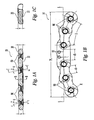
- FIG. 1A is a side cross-sectional view of a first embodiment of a bone plate having coaxial combination holes.
- FIG. 1B is a plan view of the bone plate of FIG. 1A .
- FIG. 1C is a cross-sectional view of the bone plate of FIG. 1A taken along the cross section B-B.
- FIG. 2A is a side cross-sectional view of a second embodiment of a bone plate having coaxial combination holes and having dynamic compression holes.
- FIG. 2B is a plan view of the bone plate of FIG. 2A .
- FIG. 2C is a cross-sectional view of the bone plate of FIG. 2A taken along the cross section B-B.
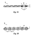
- FIG. 3A is a third embodiment of a bone plate having coaxial combination holes.
- FIG. 3B is a plan view of the bone plate of FIG. 3A .
- FIG. 4A is a cross-sectional view of one embodiment of a coaxial combination hole.
- FIG. 4B is a magnified view of a portion of the thread of the coaxial combination hole of FIG. 4A .
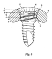
- FIG. 5 is a cross-sectional view of a screw, having a threaded head, inserted through a coaxial combination hole.
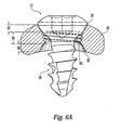
- FIG. 6A is a cross-sectional view of a screw, having a non-threaded head, inserted through a coaxial combination hole at one angle.
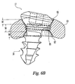
- FIG. 6B is a cross-sectional view of a unthreaded-head screw inserted through a coaxial combination hole at an angle different from that of the screw of FIG. 6A .
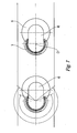
- FIG. 7 is a plan view of a segment of a bone plate having non-coaxial combination holes.
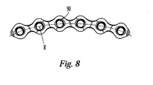
- FIG. 8 is a plan view of the bone plate of FIGS. 3A and 3B , in a curved condition.
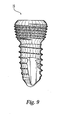
- FIG. 9 is a side view of one embodiment of a screw that has a conically-tapered threaded head.
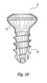
- FIG. 10 is a side view of one embodiment of a screw having an unthreaded head.
- the bone plates may have at least one coaxial combination or first hole 90, which has a lengh L that extends from the upper surface of the bone plate to the lower surface of the bone plate.
- the coaxial combination hole 90 is threaded only partially through the hole's length L.
- a surgeon may elect to: (1) thread a screw having a thread on at least a portion of its head into and through the hole; or (2) insert a screw having an unthreaded head through the hole and into the bone.
- the hole 90 has length L of approximately 3.4mm to 4.0mm which preferably corresponds to the thickness T of the bone plate.
- FIGS. 1B , 2B , and 3B illustrate plan views of various embodiments of the bone plate having at least one coaxial combination hole 90.
- Each bone plate may have at least a central region with a longitudinal axis L-L.
- Each bone plate hole 90 may have a vertical axis V-V, which is perpendicular to the plane on which the plate's upper surface lies (if the plate has a straight upper surface), or to the plane that is tangential to the pinnacle of the plate's upper surface (if the plate is convex). (See FIGS. 1A , 2A , and 3A )
- FIGS. 1C and 2C illustrate cross-sectional views of the bone plates along the respective cross sections B-B.
- the upper surface of the plate may be convex and the lower surface of the plate may be concave, as shown in FIGS 1C and 2C .
- the radius of curvature for both surfaces may be from about 15mm to about 35mm, and preferably about 25mm. In another embodiment, one or both of the plate surfaces may be flat.
- hole 90 may extend from the upper surface 20 to the lower surface 22 of the bone plate 10.
- the diameters of the hole 90 at its uppermost surface and its lower most surface may be equal or close to equal.
- the hole 90 may be widest at the uppermost surface 20 and lowermost surface 22 of the plate 10.
- Each hole 90 may have a central axis C-C. (See FIGS. 1A and 2A .)
- the central axis C-C of hole 90 will intersect with the vertical axis V-V at an angle ⁇ , as shown in FIGS. 1A and 2A .
- the angle ⁇ may vary from about 3° to about 17°, although other angles are contemplated.
- the hole 90 have three regions: an first upper region 92, a second middle region 94, and a third lower region 96.
- the upper region 92 of the hole 90 have an unthreaded inner surface 93 which, is preferably smooth, although texturing may be provided.
- the upper region 92 may have a curved inward taper, preferably concave, more preferably spherical, from the top surface of the plate to where the upper region 92 of the hole 90 meets the middle region 94.
- the upper region 92 of the hole 90 is preferably narrowest where it meets the middle region 94.
- the upper region is approximately 1.0mm to approximately 1.2mm in length (along the axis C-C).
- the upper region may comprise about 25% to about 35% of the thickness T of the plate.
- the diameter of the upper region 92, at the region's broadest point may be about 6mm and, at the region's narrowest point, may be about 4mm. In another embodiment the diameter of the upper region 92, at the region's broadest point, may be about 8mm and, at the region's narrowest point, may be about 6mm.
- the middle region 94 of the hole 90 has a threaded inner surface 95.
- the threads have a pitch P (as shown in FIG. 4B , which is a magnified partial view of the threaded surface 95) of approximately 0.3mm to 0.5mm.
- the thread angle ⁇ may be approximately 50° to 70°, and preferably about 60°.
- the threaded region has at least one thread revolution, and preferably about three thread revolutions.
- the threaded inner surface 95 may, in a direction from the upper surface to the lower surface, have a conical inward taper.
- the threaded inner surface 95 may taper at an angle ⁇ of approximately 5) to 15°, and preferably approximately 10).
- the middle region 94 may be the narrowest region (i.e., smallest-diameter region) of the hole 90.
- the middle region 94 may be approximately 1.5mm to approximately 1.9mm in length (along the axis C-C).
- the middle region 94 may comprise about 40% to 50% of the thickness T of the plate.
- the diameter of the middle region 94 may vary only slightly (due to the relatively shallow conical taper) and may be about 4mm or, in another embodiment, about 6mm. The diameter or taper of the middle region 94 may of course vary depending upon the size and/or taper of the screw.
- the lower region 96 of the hole 90 has an unthreaded inner surface 97 which is preferably smooth, although texturing may be provided.
- the lower region 96 may, from where it meets the middle region 94 to the lower surface of the plate, have a conical outward capa.
- the lower region 96 may taper outwardly at an angle ⁇ of approximately 35° to 55°, and preferably approximately 45°.
- the lower region 96 may be approximately 0.8mm to approximately 1.2mm in length (along the axis C-C).
- the lower region 96 may comprise about 20% to 35% of the thickness T of the plate.
- the diameter of the lower region 96, at the region's narrowest point may be about 4mm and, at the region's broadest point, may be about 6mm. In another embodiment, the diameter of the lower region 96, at the region's narrowest point, may be about 6mm and, at the region's broadest point, may be about 8mm.
- Screws may be used with the hole 90.
- One type of screw is a screw that has a conically-tapered threaded head (shown in FIG. 9 ). As shown in FIG. 5 , the external threads of the screw's head may mate with the internal threads 95 of the middle region 94 of the hole 90. This threaded-head screw 15 may be inserted at only one angle (with respect to the plate), which may be fixed by the threads 95 in the plate 10.
- a second type of screw that may be used with the hole 90 is a screw with a threaded shaft, but with an unthreaded head (shown in Fig. 10 ).
- An unthreaded-head screw may be inserted into hole 90 at any one of a number of angles.
- FIG. 6A illustrates an unthreaded-head screw 17 inserted at an angle substantially perpendicular to the longitudinal axis of the plate 10.
- FIG. 6B illustrates an unthreaded-head screw 17 inserted at a non-perpendicular angle with respect to the plate 10.
- the conical outward taper (shown at surface 97) of the lower region 96 of the hole 90 provides room for screw shaft 18 to be inserted at an angle with respect to the center of the hole 90.
- the curved inward taper of the upper region 92 of the hole 90 provides a seat (at surface 93) for the screw head to rest in when an unthreaded-head screw 17 is inserted at an angle.
- a threaded-head screw may be used with a coaxial combination hole 90 in the same manner as the aforementioned unthreaded-head screw 17.
- coaxial combination holes are particularly useful for pubic symphysis plates and other relatively small bone plates.
- the pubic symphysis is the connection between the two halves of the pubis and may be damaged as a result of an accident
- a bone plate having a coaxial combination hole may be more versatile than plates having other types of holes.
- the benefits may include: (1) a reduced need to manufacture many different plates having varying hole arrangement patterns; and (2) enhancement of clinical results.
- a coaxial combination hole does not require a substantially larger cavity in the bone plate than would otherwise be necessary for a simple hole, a coaxial combination hole provides desired flexibility for the surgeon without unduly compromising the strength, size, or integrity of the bone plate. Plates having coaxial combination holes may thus find particular utilization in pubic symphysis plates and other relatively small bone plates.
- the bone plate of the present invention may be a pubic symphysis plate as shown in FIG. 1B , and may have a plurality of holes, all of which may be coaxial combination holes 90.
- the plate may have a length PL of approximately 70mm to 90mm.
- the plate may have curved ends as shown in FIG. 1B , with a radius of curvature R.
- two coaxial combination holes 90 arc located on the straight center portion of the plate.
- the plate ends may curve approximately at a 45mm-55mm radius R, spanning a 25°-35° angle ⁇ .
- two coaxial combination holes 90 are placed along an ares (on both sides of the plate's straight center portion) having a radius of curvature of about 50mm.
- the hole 90 on the curved portion adjacent to the hole 90 on the straight portion is located approximately 12°-18° on the arc away from the hole 90 on the straight portion.
- the two holes 90 on either curved portion may be placed along an arc approximately 12°-18° apart from each other.
- the plate may be symmetrical from one side to the other (i.e., a mirror hole arrangement on the other side of the plate is contemplated).
- the two holes near the center of the plate may lie along the longitudinal axis L-L of the center region of the plate 10. The remaining holes may be offset from the longitudinal axis L-L, as shown in FIG. 1B .
- the central axes C-C of the holes 90 are not parallel to the respective vertical axes V-V of the holes 90.
- the two holes near the center of the plate have central axes C-C oriented to bias the tips of the screws in a direction away from the center of plate.
- the angle ⁇ between each of these two central axes C-C and the vertical axes V-V is approximately 8° to 15°.
- each of the holes 90, that are located near the ends of the plate has a central axis C-C oriented to bias the tips of the screws in a direction towards the center of plate.
- the angle ⁇ between each of these central axes C-C and the vertical axes V-V is approximately 4° to 10°.
- the linear plate-surface distance d1 between the edges of holes 90 may vary from hole to hole and may be approximately 10mm to 12mm.
- there may be necking of the plate surface in between hole locations i.e., the webs between the holes maybe narrowed. This necking serves to achieve a desired balance between plate strength and plate size: plate strength is maximized, while plate size is minimized.
- the width of the plate between holes may be the same as the width of the plate where the holes are located.
- the plate may have at least one hole 99, preferably near the center of the plate. Holes 99 may aid in the placement of the plate onto the bone (e.g., for use with a guide wire) or may be provided as a suture hole.
- a shorter bone plate having only a few (e.g., 4) holes may be used when the fracture is relatively small or when the patient's bone or joint (e.g., pubic symphysis) being operated on is relatively small.
- FIG. 2B A plan view of a second embodiment of a pubic symphysis plate is shown in FIG. 2B .
- the primary difference between this embodiment and the foregoing embodiment is that the two second holes near the center of the plate 30 of this embodiment are dynamic compression ("DC") holes 70 instead of coaxial combination holes 90.
- DC dynamic compression
- This embodiment of a bone plate is particularly useful when, to bring parts closer together, "extra" compression is desired.
- the DC holes are substantially similar is those disclosed in the specifications of United States publications No. 2002/0045901 , in U-S. patent No. 6,669,701 , and in reissued U.S. Patent No. R.E. 31,628 , the contents of which are incorporated herein by reference.
- DC hole 70 is elongated in a direction substantially aligned with the longitudinal axis L-L of the plate 30.
- DC hole 70 has an oblique portion or ramp 35 having an inclination such that when ramp 35 is engaged by the underside 13 of the head of a screw, preferably a screw having a head that is not threaded, and is preferably smooth and curved on the underside 13 which contracts the bone plate, the bone plate 30 is displaced in a direction to move ramp 35 away from the non-locking screw, causing the plate 30 to apply a pressure to hold the fracture ends in contact, preferably in engagement, along at least a portion of the fracture length.
- each of the holes 70 has a length X (illustrated in FIG. 2A ) of approximately 6mm to 7mm.
- the two holes near the center of the plate 30 may be non-coaxial combination holes 40 (instead of coaxial combination holes 90 or DC holts 70).
- the non-coaxial combination holes are substantially similar to those disclosed in the specifications of U.S. patent No. 6,669,701 and of United States publication No. 2002/0045901 , the contents of which are hereby incorporated by reference.
- FIG. 7 illustrates a bone plate having a plurality of combination holes 40, which extend from the plate's upper surface to its lower surface.
- the holes 40 may be elongated (e.g., in a direction substantially aligned with a longitudinal axis of the plate) and may include a threaded portion 5 and a non-threaded portion 6.
- the threaded portion 5 may extend over a range of greater than about 180° with respect to a center point C1.
- the threaded portion 5 of the hole 40 may be dimensioned and configured to engage a threaded head portion of a threaded-head bone screw, and fix the bone screw at a predetermined angle with respect to the bone plate.
- the threaded portion 5 of the hole 40 extends through the full thickness of the bone plate ( i.e., from the plate's upper surface to its lower surface) thus maximizing the stability of the bone screw to bone plate interface.
- a threaded-head screw or a non-threaded head screw may (e.g., for compression) pass through the non-threaded portion 6 of a combination hole 40.
- the plate 50 may have a plurality of holes, all of which may be coaxial combination holes 90.
- Each of the holes 90 may lie along the longitudinal axis L-L of the plate 50.
- the linear plate-surface distance d2 between the edges of holes 90 may be approximately 6mm to 9mm.
- FIG. 8 is the bone plate of FIGS. 3A and 3B , in a "curved condition."
- the bone plate of FIGS. 3A and 3B may be formed of such material to allow a surgeon to preoperatively bead the plate into a desired shape, a bone plate manufactured to a bend condition may be desirable.
- a ball-and-socket joint is formed by the two acetabula of the pelvis and the head of each femur.
- the bone plate of FIG. 9 may be especially useful for use on the posterior outer surface of a fractured acetabulum.
- the plate may have a radius of curvature R, which in a preferred embodiment, is about 100-115mm.
Priority Applications (1)
| Application Number | Priority Date | Filing Date | Title |
|---|---|---|---|
| PL05753705T PL1761179T3 (pl) | 2004-05-21 | 2005-05-19 | Płytka kostna |
Applications Claiming Priority (2)
| Application Number | Priority Date | Filing Date | Title |
|---|---|---|---|
| US10/851,849 US7776076B2 (en) | 2004-05-11 | 2004-05-21 | Bone plate |
| PCT/US2005/017987 WO2005112802A1 (en) | 2004-05-21 | 2005-05-19 | Bone plate |
Publications (3)
| Publication Number | Publication Date |
|---|---|
| EP1761179A1 EP1761179A1 (en) | 2007-03-14 |
| EP1761179A4 EP1761179A4 (en) | 2009-04-08 |
| EP1761179B1 true EP1761179B1 (en) | 2010-12-22 |
Family
ID=35376201
Family Applications (1)
| Application Number | Title | Priority Date | Filing Date |
|---|---|---|---|
| EP05753705A Active EP1761179B1 (en) | 2004-05-21 | 2005-05-19 | Bone plate |
Country Status (15)
| Country | Link |
|---|---|
| US (2) | US7776076B2 (es) |
| EP (1) | EP1761179B1 (es) |
| JP (1) | JP5057976B2 (es) |
| KR (1) | KR101200822B1 (es) |
| CN (2) | CN1988854B (es) |
| AT (1) | ATE492228T1 (es) |
| AU (1) | AU2005245007A1 (es) |
| BR (1) | BRPI0511274B1 (es) |
| CA (1) | CA2567321C (es) |
| DE (1) | DE602005025480D1 (es) |
| ES (1) | ES2356648T3 (es) |
| NZ (1) | NZ551911A (es) |
| PL (1) | PL1761179T3 (es) |
| WO (1) | WO2005112802A1 (es) |
| ZA (1) | ZA200610161B (es) |
Families Citing this family (150)
| Publication number | Priority date | Publication date | Assignee | Title |
|---|---|---|---|---|
| US7951176B2 (en) | 2003-05-30 | 2011-05-31 | Synthes Usa, Llc | Bone plate |
| US11259851B2 (en) | 2003-08-26 | 2022-03-01 | DePuy Synthes Products, Inc. | Bone plate |
| CA2536960C (en) | 2003-08-26 | 2011-12-06 | Synthes Gmbh | Bone plate |
| US8105367B2 (en) | 2003-09-29 | 2012-01-31 | Smith & Nephew, Inc. | Bone plate and bone plate assemblies including polyaxial fasteners |
| US8182485B1 (en) | 2003-11-21 | 2012-05-22 | Toby Orthopaedics, Llc | Fracture fixation system |
| US11291484B2 (en) | 2004-01-26 | 2022-04-05 | DePuy Synthes Products, Inc. | Highly-versatile variable-angle bone plate system |
| US8574268B2 (en) | 2004-01-26 | 2013-11-05 | DePuy Synthes Product, LLC | Highly-versatile variable-angle bone plate system |
| US7637928B2 (en) | 2004-01-26 | 2009-12-29 | Synthes Usa, Llc | Variable angle locked bone fixation system |
| US7621914B2 (en) * | 2004-10-28 | 2009-11-24 | Biodynamics, Llc | Adjustable bone plate |
| US8172886B2 (en) | 2004-12-14 | 2012-05-08 | Depuy Products, Inc. | Bone plate with pre-assembled drill guide tips |
| DE102005004841B4 (de) * | 2004-12-30 | 2009-10-29 | Königsee Implantate und Instrumente zur Osteosynthese GmbH | Osteosyntheseplatte mit einer Vielzahl von Bohrungen zur Aufnahme von Knochenschrauben |
| US8118848B2 (en) * | 2005-01-28 | 2012-02-21 | Orthohelix Surgical Designs, Inc. | Orthopedic plate for use in fibula repair |
| US8118846B2 (en) * | 2005-01-28 | 2012-02-21 | Orthohelix Surgical Designs, Inc. | Orthopedic plates for use in clavicle repair and methods for their use |
| DE102005032026B3 (de) * | 2005-07-08 | 2006-12-14 | Stryker Leibinger Gmbh & Co. Kg | Osteosyntheseplatte mit schräg zur Plattenebene verlaufenden Durchgangsöffnungen |
| US8382807B2 (en) | 2005-07-25 | 2013-02-26 | Smith & Nephew, Inc. | Systems and methods for using polyaxial plates |
| AU2006272646C1 (en) | 2005-07-25 | 2018-06-21 | Smith & Nephew, Inc. | Systems and methods for using polyaxial plates |
| US7905909B2 (en) | 2005-09-19 | 2011-03-15 | Depuy Products, Inc. | Bone stabilization system including multi-directional threaded fixation element |
| PL1800615T3 (pl) * | 2005-12-23 | 2008-04-30 | Aap Implantate Ag | Płytka kostna |
| US7935126B2 (en) | 2006-03-20 | 2011-05-03 | Depuy Products, Inc. | Bone plate shaping system |
| US7951178B2 (en) * | 2006-04-03 | 2011-05-31 | Acumed Llc | Bone plates with hybrid apertures |
| US20070270849A1 (en) * | 2006-04-21 | 2007-11-22 | Orbay Jorge L | Fixation Plate With Multifunctional Holes |
| WO2007131287A1 (en) * | 2006-05-17 | 2007-11-22 | Gordon Slater | Ankle fusion plate |
| DE102006031801A1 (de) * | 2006-07-06 | 2008-01-10 | Aap Implantate Ag | Osteosynthesisches Fixationssystem |
| US20080234749A1 (en) * | 2007-01-26 | 2008-09-25 | Zimmer Technology, Inc. | Bone plate providing threaded locking head screw capture |
| US20090216282A1 (en) * | 2007-05-18 | 2009-08-27 | Blake Doris M | Systems and methods for retaining a plate to a substrate with an asynchronous thread form |
| MY154229A (en) * | 2007-08-27 | 2015-05-15 | Adler Mediequip Private Ltd | Bone plate and bone palte assemblies |
| EP2185095A1 (de) * | 2007-09-12 | 2010-05-19 | Cendres + Métaux SA | Anordnung zur bildung einer stegkonstruktion und fixationsschraube dafür |
| CA2704451A1 (en) * | 2007-10-30 | 2009-05-07 | Alberto A. Fernandez Dell'oca | Variable angle locked bone plate |
| EP2397082B1 (en) * | 2007-11-02 | 2014-08-13 | Biomet C.V. | Elbow fracture fixation system |
| US8366752B1 (en) * | 2008-11-25 | 2013-02-05 | Jones A Alexander M | Cervical plate having graduated thickness |
| US8317842B2 (en) | 2007-11-30 | 2012-11-27 | Biomet C.V. | Distal tibia plating system |
| AU2009223517B2 (en) * | 2008-03-10 | 2015-02-12 | Eduardo Gonzalez-Hernandez | Bone fixation system |
| US20090228048A1 (en) * | 2008-03-10 | 2009-09-10 | Duncan Scott F M | Joint Fixation System For the Hand |
| AU2008354730A1 (en) | 2008-04-17 | 2009-10-22 | Toby Orthopaedics, Inc. | Soft tissue attachment system and clip |
| KR100999789B1 (ko) * | 2008-05-14 | 2010-12-08 | (주)트라디메딕스 | 접골용 보철 |
| US8257405B2 (en) * | 2008-07-31 | 2012-09-04 | Biomet C.V. | Periarticular bone plate with biplanar offset head member |
| US8262707B2 (en) * | 2008-07-31 | 2012-09-11 | Biomet C.V. | Periarticular bone plate with biplanar offset head member |
| ES2533802T3 (es) * | 2008-09-02 | 2015-04-14 | Stryker Trauma Sa | Dispositivo localizador para una placa ósea |
| US8784458B1 (en) | 2008-10-10 | 2014-07-22 | Greatbatch Medical S.A. | Polyaxial insert for surgical screws |
| US8906076B2 (en) | 2008-10-17 | 2014-12-09 | Osteomed Llc | Angulated locking plate and screw |
| US8597334B2 (en) * | 2008-10-17 | 2013-12-03 | Osteomed Llc | Angulated locking plate/screw interface |
| DE102008043370A1 (de) * | 2008-10-31 | 2010-05-06 | Universität Rostock | Fixationsvorrichtung für Knochen |
| US8366719B2 (en) | 2009-03-18 | 2013-02-05 | Integrated Spinal Concepts, Inc. | Image-guided minimal-step placement of screw into bone |
| US20100256687A1 (en) * | 2009-04-01 | 2010-10-07 | Merete Medical Gmbh | Fixation Device and Method of Use for a Ludloff Osteotomy Procedure |
| DE102009016394B4 (de) | 2009-04-07 | 2016-02-11 | Merete Medical Gmbh | Vorrichtung zur winkelstabilen Fixation und Kompression einer Bruchstelle bzw. Osteotomie an einem Knochen |
| US8986353B2 (en) | 2009-07-09 | 2015-03-24 | Orthohelix Surgical Designs, Inc. | Osteotomy plate, plate driver and method for their use |
| CN102497830A (zh) * | 2009-09-14 | 2012-06-13 | 斯恩蒂斯有限公司 | 可变角度压板 |
| US10390867B2 (en) | 2009-09-18 | 2019-08-27 | Biomet C.V. | Bone plate system and method |
| IN2012DN02761A (es) * | 2009-09-18 | 2015-09-18 | Biomet Cv | |
| US8496692B2 (en) | 2009-09-21 | 2013-07-30 | Jmea Corporation | Locking securing member |
| US8551107B2 (en) | 2009-10-15 | 2013-10-08 | Biomet, C.V. | Bending tool and method for reshaping a bone plate |
| US8348980B2 (en) | 2009-10-15 | 2013-01-08 | Biomet C.V. | Method and plate for fusing the medial column bones of the foot |
| EP2515779B1 (de) | 2009-12-22 | 2016-03-02 | Merete Medical GmbH | Knochenplattensystem für die osteosynthese |
| US20110218580A1 (en) | 2010-03-08 | 2011-09-08 | Stryker Trauma Sa | Bone fixation system with curved profile threads |
| US20110224736A1 (en) * | 2010-03-09 | 2011-09-15 | Humphrey C Scott | Proximal humerus fracture repair plate and system |
| US20120059424A1 (en) * | 2010-03-10 | 2012-03-08 | Advanced Orthopaedic Solutions, Inc. | Clavicle Bone Plate |
| US20110245871A1 (en) * | 2010-04-06 | 2011-10-06 | Williams Lytton A | Crosslink element and bender for spine surgery procedures |
| ES2427981T3 (es) * | 2010-05-25 | 2013-11-05 | Stryker Trauma Sa | Implante para fijación ósea |
| US8696715B2 (en) | 2010-06-17 | 2014-04-15 | Chris Sidebotham | Low profile medical locking plate and bone screw design for bone fractures |
| US8961573B2 (en) | 2010-10-05 | 2015-02-24 | Toby Orthopaedics, Inc. | System and method for facilitating repair and reattachment of comminuted bone portions |
| WO2012058448A2 (en) | 2010-10-27 | 2012-05-03 | Toby Orthopaedics, Llc | System and method for fracture replacement of comminuted bone fractures or portions thereof adjacent bone joints |
| US8852281B2 (en) | 2011-01-18 | 2014-10-07 | Globus Medical, Inc. | Artificial spinal disk prosthesis |
| US8709092B2 (en) | 2011-02-16 | 2014-04-29 | Genesis Medical Devices, LLC | Periprosthetic fracture management enhancements |
| WO2012119146A2 (en) | 2011-03-03 | 2012-09-07 | Toby Orthopaedics, Llc | Anterior lesser tuberosity fixed angle fixation device and method of use associated therewith |
| US8672978B2 (en) | 2011-03-04 | 2014-03-18 | Zimmer Spine, Inc. | Transverse connector |
| US8845697B2 (en) | 2011-04-01 | 2014-09-30 | DePuy Synthes Products, LLC | Posterior vertebral plating system |
| US20130046389A1 (en) * | 2011-04-11 | 2013-02-21 | Johann Fierlbeck | Acetabular Roof Reinforcement Plate |
| US20120323284A1 (en) | 2011-06-15 | 2012-12-20 | Smith & Nephew, Inc. | Variable angle locking implant |
| DE202011051165U1 (de) | 2011-08-31 | 2011-11-14 | Merete Medical Gmbh | Anatomisch angepasste, plantare Knochenplatte sowie Knochenplattensystem |
| US9271772B2 (en) | 2011-10-27 | 2016-03-01 | Toby Orthopaedics, Inc. | System and method for fracture replacement of comminuted bone fractures or portions thereof adjacent bone joints |
| US9730797B2 (en) | 2011-10-27 | 2017-08-15 | Toby Orthopaedics, Inc. | Bone joint replacement and repair assembly and method of repairing and replacing a bone joint |
| US9402667B2 (en) | 2011-11-09 | 2016-08-02 | Eduardo Gonzalez-Hernandez | Apparatus and method for use of the apparatus for fracture fixation of the distal humerus |
| US20130150902A1 (en) * | 2011-12-13 | 2013-06-13 | Neoortho Produtos Ortopedicos | Blocked bone plate and screw provided with a threaded conic or parabolic head and arrangement comprising an implant and respective insertion method of said implant to a bone tissue |
| DE102012103894B4 (de) | 2012-05-03 | 2016-10-27 | Merete Medical Gmbh | Knochenplattensystem für Osteosynthese |
| US9387022B2 (en) | 2012-06-27 | 2016-07-12 | DePuy Synthes Products, Inc. | Variable angle bone fixation device |
| US9265542B2 (en) * | 2012-06-27 | 2016-02-23 | DePuy Synthes Products, Inc. | Variable angle bone fixation device |
| US9452005B2 (en) | 2012-08-23 | 2016-09-27 | DePuy Synthes Products, Inc. | Bone fixation system |
| CN104736082B (zh) | 2012-08-23 | 2018-03-30 | 新特斯有限责任公司 | 骨植入物 |
| US10004603B2 (en) | 2012-08-23 | 2018-06-26 | DePuy Synthes Products, Inc. | Bone implant |
| RU2648850C2 (ru) * | 2012-08-23 | 2018-03-28 | Зинтес Гмбх | Система фиксации кости |
| US9283008B2 (en) | 2012-12-17 | 2016-03-15 | Toby Orthopaedics, Inc. | Bone plate for plate osteosynthesis and method for use thereof |
| US9107711B2 (en) | 2013-02-20 | 2015-08-18 | Stryker Trauma Sa | Screw thread with flattened peaks |
| US9333014B2 (en) | 2013-03-15 | 2016-05-10 | Eduardo Gonzalez-Hernandez | Bone fixation and reduction apparatus and method for fixation and reduction of a distal bone fracture and malunion |
| US9545276B2 (en) | 2013-03-15 | 2017-01-17 | Aristotech Industries Gmbh | Fixation device and method of use for a lapidus-type plantar hallux valgus procedure |
| US9510880B2 (en) * | 2013-08-13 | 2016-12-06 | Zimmer, Inc. | Polyaxial locking mechanism |
| US9468479B2 (en) | 2013-09-06 | 2016-10-18 | Cardinal Health 247, Inc. | Bone plate |
| USD745162S1 (en) | 2014-01-27 | 2015-12-08 | Merete Medical Gmbh | Bone plate |
| US10226287B2 (en) | 2014-03-31 | 2019-03-12 | Association For The Advancement Of Musculoskeletal | Bone plate with versatile screw holes |
| US10226288B2 (en) * | 2014-11-10 | 2019-03-12 | Biomedtrix, Llc | Osteotomy plate for long bones |
| US10828068B2 (en) | 2014-12-17 | 2020-11-10 | Medartis Holding Ag | Bone plate, surgical sets and reconstruction sets |
| US10314626B2 (en) * | 2015-01-16 | 2019-06-11 | DePuy Synthes Procucts, Inc. | Washer plate |
| US11076898B2 (en) | 2015-08-27 | 2021-08-03 | Globus Medical, Inc. | Proximal humeral stabilization system |
| US11197682B2 (en) | 2015-08-27 | 2021-12-14 | Globus Medical, Inc. | Proximal humeral stabilization system |
| US10687874B2 (en) | 2015-08-27 | 2020-06-23 | Globus Medical, Inc | Proximal humeral stabilization system |
| US10058363B2 (en) * | 2015-09-07 | 2018-08-28 | Karl Leibinger Medizintechnik Gmbh & Co Kg | Rib fixation system |
| US10993750B2 (en) | 2015-09-18 | 2021-05-04 | Smith & Nephew, Inc. | Bone plate |
| US10130402B2 (en) | 2015-09-25 | 2018-11-20 | Globus Medical, Inc. | Bone fixation devices having a locking feature |
| US9974581B2 (en) | 2015-11-20 | 2018-05-22 | Globus Medical, Inc. | Expandable intramedullary systems and methods of using the same |
| US10478237B2 (en) * | 2016-01-04 | 2019-11-19 | OsteoCertus, LLC | Orthopedic bone plate system |
| US10357293B2 (en) | 2016-02-02 | 2019-07-23 | Stryker European Holdings I, Llc | Bone plate with alternating chamfers |
| US9795411B2 (en) | 2016-03-02 | 2017-10-24 | Globus Medical, Inc. | Fixators for bone stabilization and associated systems and methods |
| US9962192B2 (en) * | 2016-03-17 | 2018-05-08 | Medos International Sarl | Multipoint fixation implants |
| US10531905B2 (en) | 2016-04-19 | 2020-01-14 | Globus Medical, Inc. | Implantable compression screws |
| JPWO2017208318A1 (ja) | 2016-05-31 | 2019-03-22 | オリンパステルモバイオマテリアル株式会社 | 骨プレートおよび骨プレートシステム |
| JP6936799B2 (ja) | 2016-07-25 | 2021-09-22 | オリンパステルモバイオマテリアル株式会社 | 骨手術用圧迫器具 |
| US10751098B2 (en) | 2016-08-17 | 2020-08-25 | Globus Medical Inc. | Stabilization systems |
| US11197701B2 (en) | 2016-08-17 | 2021-12-14 | Globus Medical, Inc. | Stabilization systems |
| US10575884B2 (en) | 2016-08-17 | 2020-03-03 | Globus Medical, Inc. | Fracture plates, systems, and methods |
| US11141204B2 (en) | 2016-08-17 | 2021-10-12 | Globus Medical Inc. | Wrist stabilization systems |
| US11213327B2 (en) | 2016-08-17 | 2022-01-04 | Globus Medical, Inc. | Fracture plates, systems, and methods |
| US10420596B2 (en) | 2016-08-17 | 2019-09-24 | Globus Medical, Inc. | Volar distal radius stabilization system |
| US10383668B2 (en) | 2016-08-17 | 2019-08-20 | Globus Medical, Inc. | Volar distal radius stabilization system |
| US11432857B2 (en) | 2016-08-17 | 2022-09-06 | Globus Medical, Inc. | Stabilization systems |
| US11331128B2 (en) | 2016-08-17 | 2022-05-17 | Globus Medical Inc. | Distal radius stabilization system |
| US10687873B2 (en) * | 2016-08-17 | 2020-06-23 | Globus Medical Inc. | Stabilization systems |
| US10820930B2 (en) | 2016-09-08 | 2020-11-03 | DePuy Synthes Products, Inc. | Variable angle bone plate |
| US10905476B2 (en) | 2016-09-08 | 2021-02-02 | DePuy Synthes Products, Inc. | Variable angle bone plate |
| US10624686B2 (en) | 2016-09-08 | 2020-04-21 | DePuy Synthes Products, Inc. | Variable angel bone plate |
| EP3348218B1 (en) * | 2017-01-13 | 2022-11-16 | Globus Medical, Inc. | Stabilization systems |
| WO2018156563A1 (en) * | 2017-02-21 | 2018-08-30 | William Scott Van Dyke | Implants for bridging osseous defects |
| US10881438B2 (en) | 2017-03-10 | 2021-01-05 | Globus Medical, Inc. | Clavicle fixation system |
| US10905477B2 (en) | 2017-03-13 | 2021-02-02 | Globus Medical, Inc. | Bone stabilization systems |
| US10368928B2 (en) | 2017-03-13 | 2019-08-06 | Globus Medical, Inc. | Bone stabilization systems |
| US10709566B2 (en) * | 2017-05-04 | 2020-07-14 | Wright Medical Technology, Inc. | Implant and method for ankle syndesmosis treatment |
| US11096730B2 (en) | 2017-09-13 | 2021-08-24 | Globus Medical Inc. | Bone stabilization systems |
| US10856920B2 (en) | 2017-09-13 | 2020-12-08 | Globus Medical Inc. | Bone stabilization systems |
| WO2019166851A1 (en) | 2018-02-27 | 2019-09-06 | 41Medical Ag | Variable angle bone plate system |
| US11071570B2 (en) | 2018-03-02 | 2021-07-27 | Globus Medical, Inc. | Distal tibial plating system |
| US11039865B2 (en) | 2018-03-02 | 2021-06-22 | Stryker European Operations Limited | Bone plates and associated screws |
| US11224468B2 (en) | 2018-03-02 | 2022-01-18 | Globus Medical, Inc. | Distal tibial plating system |
| US10898232B2 (en) | 2018-03-20 | 2021-01-26 | Medos International Sàrl | Multipoint fixation implants and related methods |
| US11026727B2 (en) | 2018-03-20 | 2021-06-08 | DePuy Synthes Products, Inc. | Bone plate with form-fitting variable-angle locking hole |
| US10772665B2 (en) | 2018-03-29 | 2020-09-15 | DePuy Synthes Products, Inc. | Locking structures for affixing bone anchors to a bone plate, and related systems and methods |
| US11141172B2 (en) | 2018-04-11 | 2021-10-12 | Globus Medical, Inc. | Method and apparatus for locking a drill guide in a polyaxial hole |
| US11013541B2 (en) | 2018-04-30 | 2021-05-25 | DePuy Synthes Products, Inc. | Threaded locking structures for affixing bone anchors to a bone plate, and related systems and methods |
| US11141285B2 (en) * | 2018-08-06 | 2021-10-12 | Baylor University | Carpal bone fusion device and method |
| US10925651B2 (en) | 2018-12-21 | 2021-02-23 | DePuy Synthes Products, Inc. | Implant having locking holes with collection cavity for shavings |
| US11202663B2 (en) | 2019-02-13 | 2021-12-21 | Globus Medical, Inc. | Proximal humeral stabilization systems and methods thereof |
| RU190172U1 (ru) * | 2019-03-28 | 2019-06-21 | Федеральное государственное бюджетное образовательное учреждение высшего образования "Самарский государственный медицинский университет" Министерства здравоохранения Российской Федерации | Пластина для накостного остеосинтеза |
| US11179180B2 (en) | 2019-06-11 | 2021-11-23 | DePuy Synthes Products, Inc. | Deformable threaded locking structures, and related systems and methods |
| US11944360B2 (en) | 2019-06-11 | 2024-04-02 | DePuy Synthes Products, Inc. | Deformable threaded locking structures, and related systems and methods |
| US11389209B2 (en) | 2019-07-19 | 2022-07-19 | Medos International Sarl | Surgical plating systems, devices, and related methods |
| US11426210B2 (en) | 2019-09-25 | 2022-08-30 | Medos International Sàrl | Multipoint angled fixation implants for multiple screws and related methods |
| US11129627B2 (en) | 2019-10-30 | 2021-09-28 | Globus Medical, Inc. | Method and apparatus for inserting a bone plate |
| WO2021112892A1 (en) * | 2019-12-06 | 2021-06-10 | Life Spine, Inc. | Spinal facet joint and laminoplasty implant |
| US11723647B2 (en) | 2019-12-17 | 2023-08-15 | Globus Medical, Inc. | Syndesmosis fixation assembly |
| CN115087404A (zh) | 2020-02-14 | 2022-09-20 | 美多斯国际有限公司 | 集成式多点固定螺钉 |
| KR102472323B1 (ko) * | 2020-08-21 | 2022-12-01 | 주식회사 코렌텍 | 보강 임플란트 |
| KR102568192B1 (ko) * | 2021-04-07 | 2023-08-22 | 주식회사 코렌텍 | 이종 다공성 구조가 적용된 보강 임플란트 |
| DE102021118087A1 (de) * | 2021-07-13 | 2023-01-19 | Ot Medizintechnik Gmbh | Symphysenknochenplatte und Set |
Family Cites Families (82)
| Publication number | Priority date | Publication date | Assignee | Title |
|---|---|---|---|---|
| US524290A (en) * | 1894-08-07 | Island | ||
| CH462375A (de) * | 1966-06-22 | 1968-09-15 | Synthes Ag | Osteosynthetische Druckplatte |
| USRE28841E (en) * | 1966-06-22 | 1976-06-08 | Synthes A.G. | Osteosynthetic pressure plate construction |
| USRE31628E (en) * | 1966-06-22 | 1984-07-10 | Synthes Ag | Osteosynthetic pressure plate construction |
| US3716050A (en) * | 1971-02-11 | 1973-02-13 | F Johnston | Olecranon plate |
| US3779240A (en) * | 1972-03-31 | 1973-12-18 | S Kondo | Compression plate for osteosynthesis |
| FR2233973A1 (en) | 1973-06-25 | 1975-01-17 | Chatin Robert | Osteosynthesis plate for femoral fracture surgery - has anchoring holes in ablong flat portion and widened blade |
| CH611147A5 (en) | 1977-01-07 | 1979-05-31 | Mueller Kurt | Osteosynthesis compression plate |
| CH613858A5 (es) * | 1977-04-22 | 1979-10-31 | Straumann Inst Ag | |
| FR2405062A1 (fr) | 1977-10-10 | 1979-05-04 | Dayan Robert | Plaques d'osteosynthese destinees au traitement chirurgical des fractures de l'extremite inferieure du femur |
| FR2405706A1 (fr) | 1977-10-14 | 1979-05-11 | Dayan Robert | Plaque d'osteosynthese pour le traitement chirurgical des fractures de l'extremite inferieure de l'humerus |
| FR2405705A1 (fr) | 1977-10-14 | 1979-05-11 | Dayan Robert | Plaque d'osteosynthese pour le traitement chirurgical des fractures de l'extremite superieure du tibia |
| CH645013A5 (de) * | 1980-04-14 | 1984-09-14 | Wenk Wilh Ag | Osteosynthetische kompressionsplatte. |
| CH651192A5 (de) * | 1980-11-20 | 1985-09-13 | Synthes Ag | Osteosynthetische vorrichtung und dazu passende bohrlehre. |
| DE8034274U1 (de) | 1980-12-23 | 1981-05-27 | Schwan-Stabilo Schwanhäußer GmbH & Co, 8500 Nürnberg | Kosmetikstift |
| CH650915A5 (de) * | 1981-03-16 | 1985-08-30 | Synthes Ag | Vorrichtung zur stabilisierung des bereiches eines knochenbruches oder einer osteotomie. |
| AT378324B (de) * | 1982-09-13 | 1985-07-25 | Streli Elke | Zinkenplatte zur gegenseitigen lagefixierung der knochenteile bei knochenbruechen |
| DE8431616U1 (de) * | 1984-10-27 | 1984-12-20 | Howmedica International, Inc. Zweigniederlassung Kiel, 2314 Schönkirchen | Platte für die Osteosynthese |
| SU1279626A1 (ru) | 1985-06-06 | 1986-12-30 | Центральный научно-исследовательский институт травматологии и ортопедии им.Н.Н.Приорова | Компрессирующее устройство дл остеосинтеза |
| DE8519854U1 (de) | 1985-07-05 | 1986-04-30 | Mecron Medizinische Produkte Gmbh, 1000 Berlin | Selbstspannende gerade Knochenplatte |
| CH668174A5 (de) | 1985-08-30 | 1988-12-15 | Synthes Ag | Osteosynthetische druckplatte. |
| US4776330A (en) * | 1986-06-23 | 1988-10-11 | Pfizer Hospital Products Group, Inc. | Modular femoral fixation system |
| US5190544A (en) * | 1986-06-23 | 1993-03-02 | Pfizer Hospital Products Group, Inc. | Modular femoral fixation system |
| US5151103A (en) * | 1987-11-03 | 1992-09-29 | Synthes (U.S.A.) | Point contact bone compression plate |
| CH673762A5 (es) * | 1987-12-02 | 1990-04-12 | Synthes Ag | |
| DE8808123U1 (es) * | 1988-06-24 | 1988-09-22 | Herzberg, Wolfgang, Dr. Med., 2000 Wedel, De | |
| US4927421A (en) * | 1989-05-15 | 1990-05-22 | Marlowe Goble E | Process of endosteal fixation of a ligament |
| US5006120A (en) * | 1989-10-10 | 1991-04-09 | Carter Peter R | Distal radial fracture set and method for repairing distal radial fractures |
| DE3942326A1 (de) * | 1989-12-21 | 1991-06-27 | Haerle Anton | Schraube als osteosynthesehilfsmittel |
| US5085660A (en) * | 1990-11-19 | 1992-02-04 | Lin Kwan C | Innovative locking plate system |
| US5129901A (en) * | 1991-06-10 | 1992-07-14 | Decoste Vern X | Cannulated orthopedic screw |
| US5275601A (en) * | 1991-09-03 | 1994-01-04 | Synthes (U.S.A) | Self-locking resorbable screws and plates for internal fixation of bone fractures and tendon-to-bone attachment |
| CH686339A5 (de) * | 1991-12-10 | 1996-03-15 | Synthes Ag | Schraubenmutter fuer die Plattenosteosynthese. |
| US5304180A (en) * | 1992-01-17 | 1994-04-19 | Slocum D Barclay | Tibial osteotomy fixation plate |
| US5197966A (en) * | 1992-05-22 | 1993-03-30 | Sommerkamp T Greg | Radiodorsal buttress blade plate implant for repairing distal radius fractures |
| US5365399A (en) * | 1992-08-03 | 1994-11-15 | Motorola, Inc. | Heat sinking apparatus for surface mountable power devices |
| US5324290A (en) | 1992-09-24 | 1994-06-28 | Danek Medical, Inc. | Anterior thoracolumbar plate |
| US5364399A (en) | 1993-02-05 | 1994-11-15 | Danek Medical, Inc. | Anterior cervical plating system |
| DE9321544U1 (de) | 1993-12-09 | 1999-09-23 | Koenigsee Implantate & Instr | Osteosynthetische Platte |
| DE4341980B4 (de) | 1993-12-09 | 2005-02-17 | Königsee Implantate und Instrumente zur Ostheosynthese GmbH | Osteosynthetische Knochenplatte |
| DE4343117C2 (de) | 1993-12-17 | 1999-11-04 | Dietmar Wolter | Fixationssystem für Knochen |
| DE4438264C2 (de) | 1994-09-08 | 1996-11-28 | Schaefer Micomed Gmbh | Osteosynthesevorrichtung |
| US5810823A (en) * | 1994-09-12 | 1998-09-22 | Synthes (U.S.A.) | Osteosynthetic bone plate and lock washer |
| US5601553A (en) * | 1994-10-03 | 1997-02-11 | Synthes (U.S.A.) | Locking plate and bone screw |
| DE59508718D1 (de) * | 1995-03-27 | 2000-10-19 | Synthes Ag | Knochenplatte |
| US5520690A (en) * | 1995-04-13 | 1996-05-28 | Errico; Joseph P. | Anterior spinal polyaxial locking screw plate assembly |
| DE59509247D1 (de) | 1995-09-06 | 2001-06-13 | Synthes Ag | Knochenplatte |
| US5702399A (en) * | 1996-05-16 | 1997-12-30 | Pioneer Laboratories, Inc. | Surgical cable screw connector |
| ES2253809T5 (es) * | 1997-02-11 | 2009-05-25 | Zimmer Spine, Inc. | Sistema de colocacion de placas cervicales anteriores. |
| US5954722A (en) * | 1997-07-29 | 1999-09-21 | Depuy Acromed, Inc. | Polyaxial locking plate |
| JP3596809B2 (ja) * | 1997-09-04 | 2004-12-02 | ジンテーズ アクチエンゲゼルシャフト クール | 対称骨プレート |
| US7052499B2 (en) * | 1998-02-18 | 2006-05-30 | Walter Lorenz Surgical, Inc. | Method and apparatus for bone fracture fixation |
| US5938664A (en) * | 1998-03-31 | 1999-08-17 | Zimmer, Inc. | Orthopaedic bone plate |
| US6533786B1 (en) * | 1999-10-13 | 2003-03-18 | Sdgi Holdings, Inc. | Anterior cervical plating system |
| US6302883B1 (en) * | 1998-10-22 | 2001-10-16 | Depuy Acromed, Inc. | Bone plate-ratcheting compression apparatus |
| US6183475B1 (en) * | 1998-12-18 | 2001-02-06 | Sulzer Orthopedics Inc. | Distal femoral osteotomy system and method |
| DE19858889B4 (de) | 1998-12-19 | 2008-08-07 | Wolter, Dietmar, Prof. Dr.Med. | Fixationssystem für Knochen |
| ES2223163T3 (es) | 1999-03-09 | 2005-02-16 | Synthes Ag Chur | Placa para osteosintesis con roscado conico. |
| DE59910412D1 (de) | 1999-03-09 | 2004-10-07 | Synthes Ag | Knochenplatte |
| US6342055B1 (en) * | 1999-04-29 | 2002-01-29 | Theken Surgical Llc | Bone fixation system |
| DE50009225D1 (de) * | 1999-05-03 | 2005-02-17 | Medartis Ag Basel | Verblockbare knochenplatte |
| PT1211992E (pt) * | 1999-09-13 | 2004-06-30 | Synthes Ag | Sistema de placa de osso |
| EP1211993B1 (de) * | 1999-09-14 | 2005-10-26 | Dietmar Prof. Dr. Wolter | Fixationssystem für knochen |
| CA2398372C (en) * | 2000-01-27 | 2007-01-09 | Synthes (U.S.A.) | Bone plate |
| US6440135B2 (en) * | 2000-02-01 | 2002-08-27 | Hand Innovations, Inc. | Volar fixation system with articulating stabilization pegs |
| US6358250B1 (en) * | 2000-02-01 | 2002-03-19 | Hand Innovations, Inc. | Volar fixation system |
| US6767351B2 (en) * | 2000-02-01 | 2004-07-27 | Hand Innovations, Inc. | Fixation system with multidirectional stabilization pegs |
| DE20007908U1 (de) * | 2000-05-03 | 2000-12-21 | Medartis Ag Basel | Konturierte Knochenplatte |
| AU2000252043B2 (en) * | 2000-06-26 | 2004-10-21 | Synthes Gmbh | Bone plate for osteosynthesis |
| DE10224005B4 (de) * | 2002-05-29 | 2015-08-13 | Stryker Leibinger Gmbh & Co. Kg | Trenn-/Biegesystem zum Anpassen einer Knochenplatte |
| US7179260B2 (en) * | 2003-09-29 | 2007-02-20 | Smith & Nephew, Inc. | Bone plates and bone plate assemblies |
| US6955677B2 (en) * | 2002-10-15 | 2005-10-18 | The University Of North Carolina At Chapel Hill | Multi-angular fastening apparatus and method for surgical bone screw/plate systems |
| USD479331S1 (en) * | 2002-11-05 | 2003-09-02 | Zimmer | Orthopedic bone plate |
| US20040097937A1 (en) * | 2002-11-19 | 2004-05-20 | Sandi Pike | Orthopedic bone plate |
| ATE331475T1 (de) * | 2003-03-20 | 2006-07-15 | Stryker Trauma Sa | Knochenverbindungsvorrichtung |
| BRPI0408769A (pt) * | 2003-03-26 | 2006-03-28 | Swiss Orthopedic Solutions Sa | placa óssea de trava |
| US7722653B2 (en) | 2003-03-26 | 2010-05-25 | Greatbatch Medical S.A. | Locking bone plate |
| US7951176B2 (en) | 2003-05-30 | 2011-05-31 | Synthes Usa, Llc | Bone plate |
| US7637928B2 (en) * | 2004-01-26 | 2009-12-29 | Synthes Usa, Llc | Variable angle locked bone fixation system |
| US7491221B2 (en) * | 2004-03-23 | 2009-02-17 | Stryker Spine | Modular polyaxial bone screw and plate |
| US7488327B2 (en) * | 2004-04-12 | 2009-02-10 | Synthes (U.S.A.) | Free hand drill guide |
| US20050277937A1 (en) * | 2004-06-10 | 2005-12-15 | Leung Takkwong R | Bone plating system |
-
2004
- 2004-05-21 US US10/851,849 patent/US7776076B2/en active Active
-
2005
- 2005-05-19 CN CN2005800246937A patent/CN1988854B/zh active Active
- 2005-05-19 JP JP2007527532A patent/JP5057976B2/ja active Active
- 2005-05-19 NZ NZ551911A patent/NZ551911A/en unknown
- 2005-05-19 BR BRPI0511274-5A patent/BRPI0511274B1/pt active IP Right Grant
- 2005-05-19 EP EP05753705A patent/EP1761179B1/en active Active
- 2005-05-19 ES ES05753705T patent/ES2356648T3/es active Active
- 2005-05-19 ZA ZA200610161A patent/ZA200610161B/en unknown
- 2005-05-19 DE DE602005025480T patent/DE602005025480D1/de active Active
- 2005-05-19 AU AU2005245007A patent/AU2005245007A1/en not_active Abandoned
- 2005-05-19 CA CA2567321A patent/CA2567321C/en not_active Expired - Fee Related
- 2005-05-19 PL PL05753705T patent/PL1761179T3/pl unknown
- 2005-05-19 CN CN201310174058.3A patent/CN103356277B/zh active Active
- 2005-05-19 AT AT05753705T patent/ATE492228T1/de active
- 2005-05-19 KR KR1020067026996A patent/KR101200822B1/ko not_active IP Right Cessation
- 2005-05-19 WO PCT/US2005/017987 patent/WO2005112802A1/en active Application Filing
-
2010
- 2010-07-08 US US12/832,466 patent/US20100274247A1/en not_active Abandoned
Also Published As
| Publication number | Publication date |
|---|---|
| WO2005112802A1 (en) | 2005-12-01 |
| CN1988854B (zh) | 2013-06-19 |
| US20100274247A1 (en) | 2010-10-28 |
| ES2356648T3 (es) | 2011-04-11 |
| AU2005245007A1 (en) | 2005-12-01 |
| JP5057976B2 (ja) | 2012-10-24 |
| JP2008500143A (ja) | 2008-01-10 |
| ATE492228T1 (de) | 2011-01-15 |
| CN103356277A (zh) | 2013-10-23 |
| AU2005245007A8 (en) | 2009-05-14 |
| US20050261688A1 (en) | 2005-11-24 |
| CN103356277B (zh) | 2016-08-10 |
| EP1761179A4 (en) | 2009-04-08 |
| BRPI0511274A (pt) | 2007-12-04 |
| CN1988854A (zh) | 2007-06-27 |
| CA2567321C (en) | 2013-09-17 |
| BRPI0511274B1 (pt) | 2022-09-27 |
| KR101200822B1 (ko) | 2012-11-13 |
| ZA200610161B (en) | 2008-06-25 |
| DE602005025480D1 (de) | 2011-02-03 |
| NZ551911A (en) | 2010-09-30 |
| PL1761179T3 (pl) | 2011-05-31 |
| CA2567321A1 (en) | 2005-12-01 |
| KR20070037714A (ko) | 2007-04-06 |
| EP1761179A1 (en) | 2007-03-14 |
| US7776076B2 (en) | 2010-08-17 |
Similar Documents
| Publication | Publication Date | Title |
|---|---|---|
| EP1761179B1 (en) | Bone plate | |
| JP4619048B2 (ja) | 骨接合プレートまたは類似のインプラントおよび球状ソケット | |
| US9820787B2 (en) | Apparatus for the constant-angle fixation and compression of a fracture or osteotomy of a bone | |
| CN102188282B (zh) | 具有弯曲形状螺纹的骨固定系统 | |
| US8998903B2 (en) | Wedge opening osteotomy plate | |
| CA2448522C (en) | Bone plate for the fixation of fractures of the proximal humerus | |
| CA2367088C (en) | Bone plate with conical screw threads | |
| US10052142B2 (en) | Bone plate with enlarged angle of inclination for a bone anchor to a favored side | |
| EP3768181B1 (en) | Bone plate with form-fitting variable-angle locking hole | |
| US20090088807A1 (en) | Locking Screw System With Relatively Hard Spiked Polyaxial Bushing | |
| US20210196329A1 (en) | Floating Locking Insert | |
| US20220226025A1 (en) | Anchoring member for a polyaxial bone anchoring device and polyaxial bone anchoring device with such an anchoring member | |
| EP3572020B1 (en) | Bone fixation assembly with enlarged angle of inclination for a bone anchor to a favored side |
Legal Events
| Date | Code | Title | Description |
|---|---|---|---|
| PUAI | Public reference made under article 153(3) epc to a published international application that has entered the european phase |
Free format text: ORIGINAL CODE: 0009012 |
|
| 17P | Request for examination filed |
Effective date: 20061221 |
|
| AK | Designated contracting states |
Kind code of ref document: A1 Designated state(s): AT BE BG CH CY CZ DE DK EE ES FI FR GB GR HU IE IS IT LI LT LU MC NL PL PT RO SE SI SK TR |
|
| RIN1 | Information on inventor provided before grant (corrected) |
Inventor name: BOLHOFNER, BRETT, R. Inventor name: MAYO, KEITH, A. Inventor name: KOAY, KENNY Inventor name: GRADY, MARK, P., JR Inventor name: MAST, JEFF, W. |
|
| DAX | Request for extension of the european patent (deleted) | ||
| A4 | Supplementary search report drawn up and despatched |
Effective date: 20090310 |
|
| 17Q | First examination report despatched |
Effective date: 20090817 |
|
| GRAP | Despatch of communication of intention to grant a patent |
Free format text: ORIGINAL CODE: EPIDOSNIGR1 |
|
| GRAS | Grant fee paid |
Free format text: ORIGINAL CODE: EPIDOSNIGR3 |
|
| GRAA | (expected) grant |
Free format text: ORIGINAL CODE: 0009210 |
|
| AK | Designated contracting states |
Kind code of ref document: B1 Designated state(s): AT BE BG CH CY CZ DE DK EE ES FI FR GB GR HU IE IS IT LI LT LU MC NL PL PT RO SE SI SK TR |
|
| REG | Reference to a national code |
Ref country code: GB Ref legal event code: FG4D |
|
| REG | Reference to a national code |
Ref country code: CH Ref legal event code: EP |
|
| REG | Reference to a national code |
Ref country code: IE Ref legal event code: FG4D |
|
| REG | Reference to a national code |
Ref country code: CH Ref legal event code: NV Representative=s name: ROSENICH PAUL; GISLER CHRISTIAN PATENTBUERO PAUL R |
|
| REF | Corresponds to: |
Ref document number: 602005025480 Country of ref document: DE Date of ref document: 20110203 Kind code of ref document: P |
|
| REG | Reference to a national code |
Ref country code: DE Ref legal event code: R096 Ref document number: 602005025480 Country of ref document: DE Effective date: 20110203 |
|
| REG | Reference to a national code |
Ref country code: ES Ref legal event code: FG2A Ref document number: 2356648 Country of ref document: ES Kind code of ref document: T3 Effective date: 20110411 |
|
| REG | Reference to a national code |
Ref country code: NL Ref legal event code: VDEP Effective date: 20101222 |
|
| PG25 | Lapsed in a contracting state [announced via postgrant information from national office to epo] |
Ref country code: LT Free format text: LAPSE BECAUSE OF FAILURE TO SUBMIT A TRANSLATION OF THE DESCRIPTION OR TO PAY THE FEE WITHIN THE PRESCRIBED TIME-LIMIT Effective date: 20101222 |
|
| LTIE | Lt: invalidation of european patent or patent extension |
Effective date: 20101222 |
|
| PG25 | Lapsed in a contracting state [announced via postgrant information from national office to epo] |
Ref country code: FI Free format text: LAPSE BECAUSE OF FAILURE TO SUBMIT A TRANSLATION OF THE DESCRIPTION OR TO PAY THE FEE WITHIN THE PRESCRIBED TIME-LIMIT Effective date: 20101222 Ref country code: SE Free format text: LAPSE BECAUSE OF FAILURE TO SUBMIT A TRANSLATION OF THE DESCRIPTION OR TO PAY THE FEE WITHIN THE PRESCRIBED TIME-LIMIT Effective date: 20101222 Ref country code: SI Free format text: LAPSE BECAUSE OF FAILURE TO SUBMIT A TRANSLATION OF THE DESCRIPTION OR TO PAY THE FEE WITHIN THE PRESCRIBED TIME-LIMIT Effective date: 20101222 Ref country code: BG Free format text: LAPSE BECAUSE OF FAILURE TO SUBMIT A TRANSLATION OF THE DESCRIPTION OR TO PAY THE FEE WITHIN THE PRESCRIBED TIME-LIMIT Effective date: 20110322 Ref country code: CY Free format text: LAPSE BECAUSE OF FAILURE TO SUBMIT A TRANSLATION OF THE DESCRIPTION OR TO PAY THE FEE WITHIN THE PRESCRIBED TIME-LIMIT Effective date: 20101222 |
|
| REG | Reference to a national code |
Ref country code: PL Ref legal event code: T3 |
|
| REG | Reference to a national code |
Ref country code: HU Ref legal event code: AG4A Ref document number: E010248 Country of ref document: HU |
|
| PG25 | Lapsed in a contracting state [announced via postgrant information from national office to epo] |
Ref country code: BE Free format text: LAPSE BECAUSE OF FAILURE TO SUBMIT A TRANSLATION OF THE DESCRIPTION OR TO PAY THE FEE WITHIN THE PRESCRIBED TIME-LIMIT Effective date: 20101222 Ref country code: GR Free format text: LAPSE BECAUSE OF FAILURE TO SUBMIT A TRANSLATION OF THE DESCRIPTION OR TO PAY THE FEE WITHIN THE PRESCRIBED TIME-LIMIT Effective date: 20110323 Ref country code: CZ Free format text: LAPSE BECAUSE OF FAILURE TO SUBMIT A TRANSLATION OF THE DESCRIPTION OR TO PAY THE FEE WITHIN THE PRESCRIBED TIME-LIMIT Effective date: 20101222 Ref country code: EE Free format text: LAPSE BECAUSE OF FAILURE TO SUBMIT A TRANSLATION OF THE DESCRIPTION OR TO PAY THE FEE WITHIN THE PRESCRIBED TIME-LIMIT Effective date: 20101222 Ref country code: IS Free format text: LAPSE BECAUSE OF FAILURE TO SUBMIT A TRANSLATION OF THE DESCRIPTION OR TO PAY THE FEE WITHIN THE PRESCRIBED TIME-LIMIT Effective date: 20110422 Ref country code: PT Free format text: LAPSE BECAUSE OF FAILURE TO SUBMIT A TRANSLATION OF THE DESCRIPTION OR TO PAY THE FEE WITHIN THE PRESCRIBED TIME-LIMIT Effective date: 20110422 |
|
| PG25 | Lapsed in a contracting state [announced via postgrant information from national office to epo] |
Ref country code: NL Free format text: LAPSE BECAUSE OF FAILURE TO SUBMIT A TRANSLATION OF THE DESCRIPTION OR TO PAY THE FEE WITHIN THE PRESCRIBED TIME-LIMIT Effective date: 20101222 Ref country code: SK Free format text: LAPSE BECAUSE OF FAILURE TO SUBMIT A TRANSLATION OF THE DESCRIPTION OR TO PAY THE FEE WITHIN THE PRESCRIBED TIME-LIMIT Effective date: 20101222 Ref country code: RO Free format text: LAPSE BECAUSE OF FAILURE TO SUBMIT A TRANSLATION OF THE DESCRIPTION OR TO PAY THE FEE WITHIN THE PRESCRIBED TIME-LIMIT Effective date: 20101222 |
|
| PLBE | No opposition filed within time limit |
Free format text: ORIGINAL CODE: 0009261 |
|
| STAA | Information on the status of an ep patent application or granted ep patent |
Free format text: STATUS: NO OPPOSITION FILED WITHIN TIME LIMIT |
|
| PG25 | Lapsed in a contracting state [announced via postgrant information from national office to epo] |
Ref country code: DK Free format text: LAPSE BECAUSE OF FAILURE TO SUBMIT A TRANSLATION OF THE DESCRIPTION OR TO PAY THE FEE WITHIN THE PRESCRIBED TIME-LIMIT Effective date: 20101222 |
|
| 26N | No opposition filed |
Effective date: 20110923 |
|
| REG | Reference to a national code |
Ref country code: DE Ref legal event code: R082 Ref document number: 602005025480 Country of ref document: DE Representative=s name: KSNH PATENTANWAELTE KLUNKER/SCHMITT-NILSON/HIR, DE Ref country code: DE Ref legal event code: R082 Ref document number: 602005025480 Country of ref document: DE Representative=s name: KLUNKER IP PATENTANWAELTE PARTG MBB, DE |
|
| PG25 | Lapsed in a contracting state [announced via postgrant information from national office to epo] |
Ref country code: MC Free format text: LAPSE BECAUSE OF NON-PAYMENT OF DUE FEES Effective date: 20110531 |
|
| REG | Reference to a national code |
Ref country code: DE Ref legal event code: R097 Ref document number: 602005025480 Country of ref document: DE Effective date: 20110923 |
|
| REG | Reference to a national code |
Ref country code: IE Ref legal event code: MM4A |
|
| PG25 | Lapsed in a contracting state [announced via postgrant information from national office to epo] |
Ref country code: IE Free format text: LAPSE BECAUSE OF NON-PAYMENT OF DUE FEES Effective date: 20110519 |
|
| PG25 | Lapsed in a contracting state [announced via postgrant information from national office to epo] |
Ref country code: LU Free format text: LAPSE BECAUSE OF NON-PAYMENT OF DUE FEES Effective date: 20110519 |
|
| PG25 | Lapsed in a contracting state [announced via postgrant information from national office to epo] |
Ref country code: TR Free format text: LAPSE BECAUSE OF FAILURE TO SUBMIT A TRANSLATION OF THE DESCRIPTION OR TO PAY THE FEE WITHIN THE PRESCRIBED TIME-LIMIT Effective date: 20101222 |
|
| PGFP | Annual fee paid to national office [announced via postgrant information from national office to epo] |
Ref country code: ES Payment date: 20150413 Year of fee payment: 11 |
|
| PGFP | Annual fee paid to national office [announced via postgrant information from national office to epo] |
Ref country code: AT Payment date: 20150427 Year of fee payment: 11 |
|
| REG | Reference to a national code |
Ref country code: FR Ref legal event code: PLFP Year of fee payment: 12 |
|
| REG | Reference to a national code |
Ref country code: AT Ref legal event code: MM01 Ref document number: 492228 Country of ref document: AT Kind code of ref document: T Effective date: 20160519 |
|
| PG25 | Lapsed in a contracting state [announced via postgrant information from national office to epo] |
Ref country code: AT Free format text: LAPSE BECAUSE OF NON-PAYMENT OF DUE FEES Effective date: 20160519 |
|
| REG | Reference to a national code |
Ref country code: FR Ref legal event code: PLFP Year of fee payment: 13 |
|
| REG | Reference to a national code |
Ref country code: DE Ref legal event code: R082 Ref document number: 602005025480 Country of ref document: DE Representative=s name: KLUNKER IP PATENTANWAELTE PARTG MBB, DE |
|
| PGFP | Annual fee paid to national office [announced via postgrant information from national office to epo] |
Ref country code: PL Payment date: 20170413 Year of fee payment: 13 |
|
| PGFP | Annual fee paid to national office [announced via postgrant information from national office to epo] |
Ref country code: HU Payment date: 20170424 Year of fee payment: 13 |
|
| REG | Reference to a national code |
Ref country code: FR Ref legal event code: PLFP Year of fee payment: 14 |
|
| PG25 | Lapsed in a contracting state [announced via postgrant information from national office to epo] |
Ref country code: ES Free format text: LAPSE BECAUSE OF NON-PAYMENT OF DUE FEES Effective date: 20160520 |
|
| REG | Reference to a national code |
Ref country code: ES Ref legal event code: FD2A Effective date: 20181204 |
|
| PG25 | Lapsed in a contracting state [announced via postgrant information from national office to epo] |
Ref country code: HU Free format text: LAPSE BECAUSE OF NON-PAYMENT OF DUE FEES Effective date: 20180520 |
|
| PG25 | Lapsed in a contracting state [announced via postgrant information from national office to epo] |
Ref country code: PL Free format text: LAPSE BECAUSE OF NON-PAYMENT OF DUE FEES Effective date: 20180519 |
|
| REG | Reference to a national code |
Ref country code: CH Ref legal event code: PCAR Free format text: NEW ADDRESS: ROTENBODENSTRASSE 12, 9497 TRIESENBERG (LI) |
|
| REG | Reference to a national code |
Ref country code: FR Ref legal event code: PLFP Year of fee payment: 19 |
|
| PGFP | Annual fee paid to national office [announced via postgrant information from national office to epo] |
Ref country code: GB Payment date: 20230330 Year of fee payment: 19 |
|
| PGFP | Annual fee paid to national office [announced via postgrant information from national office to epo] |
Ref country code: IT Payment date: 20230412 Year of fee payment: 19 Ref country code: FR Payment date: 20230411 Year of fee payment: 19 Ref country code: DE Payment date: 20230331 Year of fee payment: 19 Ref country code: CH Payment date: 20230602 Year of fee payment: 19 |