EP1760834A2 - Assemblage de bornes électriques - Google Patents
Assemblage de bornes électriques Download PDFInfo
- Publication number
- EP1760834A2 EP1760834A2 EP06016756A EP06016756A EP1760834A2 EP 1760834 A2 EP1760834 A2 EP 1760834A2 EP 06016756 A EP06016756 A EP 06016756A EP 06016756 A EP06016756 A EP 06016756A EP 1760834 A2 EP1760834 A2 EP 1760834A2
- Authority
- EP
- European Patent Office
- Prior art keywords
- contact
- electrical connection
- side cable
- arrangement according
- connection arrangement
- Prior art date
- Legal status (The legal status is an assumption and is not a legal conclusion. Google has not performed a legal analysis and makes no representation as to the accuracy of the status listed.)
- Granted
Links
- 239000012777 electrically insulating material Substances 0.000 claims description 2
- 241000196324 Embryophyta Species 0.000 description 5
- 238000000034 method Methods 0.000 description 4
- 238000003780 insertion Methods 0.000 description 3
- 230000037431 insertion Effects 0.000 description 3
- 238000004804 winding Methods 0.000 description 3
- 239000004020 conductor Substances 0.000 description 2
- 238000010276 construction Methods 0.000 description 2
- 230000006378 damage Effects 0.000 description 2
- 238000009413 insulation Methods 0.000 description 2
- 241000233805 Phoenix Species 0.000 description 1
- 208000027418 Wounds and injury Diseases 0.000 description 1
- 239000003990 capacitor Substances 0.000 description 1
- 238000006073 displacement reaction Methods 0.000 description 1
- 208000014674 injury Diseases 0.000 description 1
- 238000009434 installation Methods 0.000 description 1
- 239000000463 material Substances 0.000 description 1
- 238000003825 pressing Methods 0.000 description 1
Images

Classifications
-
- H—ELECTRICITY
- H01—ELECTRIC ELEMENTS
- H01R—ELECTRICALLY-CONDUCTIVE CONNECTIONS; STRUCTURAL ASSOCIATIONS OF A PLURALITY OF MUTUALLY-INSULATED ELECTRICAL CONNECTING ELEMENTS; COUPLING DEVICES; CURRENT COLLECTORS
- H01R4/00—Electrically-conductive connections between two or more conductive members in direct contact, i.e. touching one another; Means for effecting or maintaining such contact; Electrically-conductive connections having two or more spaced connecting locations for conductors and using contact members penetrating insulation
- H01R4/24—Connections using contact members penetrating or cutting insulation or cable strands
- H01R4/2416—Connections using contact members penetrating or cutting insulation or cable strands the contact members having insulation-cutting edges, e.g. of tuning fork type
- H01R4/242—Connections using contact members penetrating or cutting insulation or cable strands the contact members having insulation-cutting edges, e.g. of tuning fork type the contact members being plates having a single slot
- H01R4/2425—Flat plates, e.g. multi-layered flat plates
- H01R4/2429—Flat plates, e.g. multi-layered flat plates mounted in an insulating base
- H01R4/2433—Flat plates, e.g. multi-layered flat plates mounted in an insulating base one part of the base being movable to push the cable into the slot
-
- H—ELECTRICITY
- H01—ELECTRIC ELEMENTS
- H01R—ELECTRICALLY-CONDUCTIVE CONNECTIONS; STRUCTURAL ASSOCIATIONS OF A PLURALITY OF MUTUALLY-INSULATED ELECTRICAL CONNECTING ELEMENTS; COUPLING DEVICES; CURRENT COLLECTORS
- H01R4/00—Electrically-conductive connections between two or more conductive members in direct contact, i.e. touching one another; Means for effecting or maintaining such contact; Electrically-conductive connections having two or more spaced connecting locations for conductors and using contact members penetrating insulation
- H01R4/28—Clamped connections, spring connections
- H01R4/48—Clamped connections, spring connections utilising a spring, clip, or other resilient member
- H01R4/4809—Clamped connections, spring connections utilising a spring, clip, or other resilient member using a leaf spring to bias the conductor toward the busbar
- H01R4/4828—Spring-activating arrangements mounted on or integrally formed with the spring housing
- H01R4/48365—Spring-activating arrangements mounted on or integrally formed with the spring housing with integral release means
-
- H—ELECTRICITY
- H01—ELECTRIC ELEMENTS
- H01R—ELECTRICALLY-CONDUCTIVE CONNECTIONS; STRUCTURAL ASSOCIATIONS OF A PLURALITY OF MUTUALLY-INSULATED ELECTRICAL CONNECTING ELEMENTS; COUPLING DEVICES; CURRENT COLLECTORS
- H01R2201/00—Connectors or connections adapted for particular applications
- H01R2201/22—Connectors or connections adapted for particular applications for transformers or coils
Definitions
- the invention relates to an electrical connection arrangement for the electrical connection of an electrical device, in particular an electric motor, with a lower part for receiving at least one device-side cable, with an upper part for receiving at least one connection-side cable and with a contact body for electrical connection of the device-side cable to the connection side Cable, wherein the lower part and the upper part consist essentially of electrically insulating material.
- Terminal blocks for example, are known from plant construction and are usually provided in a control cabinet for top hat rail mounting and consist of a lower part and an upper part ( Phoenix Contact Product Catalog "COMBICON - PCB Connection", 2000/01, pages 198-212 ).
- a device-side cable which has been freed from its end insulation, inserted into the lower part and there electrically connected to a arranged in the lower part of the contact body by a clamping or screw connection.
- Connection-side, stripped cable are then attached to or in a contact body, which is arranged in the upper part designed as a plug strip.
- connection arrangement which, however, is tailored to the specific use for connecting a connection cable to the stator winding ends of an external rotor motor.
- the lower part of this connection arrangement is provided for mounting on the motor housing, wherein the device-side cable - so the motor-side coil ends - are electrically connected to arranged in the lower part Kunststoffkörpem, which formed as cutting contacts are; the necessity of a preliminary stripping of the device-side cable ends does not exist.
- the distributed contact bodies each extend as far as a plug receptacle formed in the lower part into which the upper part designed as a plug strip can be inserted.
- Corresponding contact bodies which are in turn electrically connectable to the connection-side cables are arranged in the upper part.
- About jumpers that can be inserted into the upper part, arranged in the upper part contact body can be electrically connected to each other, which is used in particular to the desired interconnection of the motor windings to a star or triangular arrangement.
- the invention is therefore based on the object to provide an electrical connection arrangement with improved and simplified connection properties available.
- the electrical connection arrangement according to the invention in which this object is achieved, is initially and essentially characterized in that in the lower part at least one fastening means for fixing at least one device-side cable is formed, that the contact body is arranged in the upper part, that the contact body a first Having contact means and a second contact means, and that the contact body in the joining position of the lower part with the upper part with the first contact means contacted the device-side cable and the connection side cable is contactable with the second contact means.
- the electrical connection arrangement according to the invention is advantageous in several respects.
- the fact that the contact body is arranged in the upper part of the terminal assembly eliminates a contact point with respect to the known from the prior art terminal arrangements, namely the contact point between the arranged in the lower part and the upper part in the contact body.
- the contacting process of the device-side cable is much easier and safer, since the contact between the contact body and device-side cable is made only in the joining position of the lower part and the upper part. There is thus neither the risk of mechanical damage to the first contact means producing the connection nor the risk of an electric shock by touching the possibly under tension first contact means.
- connection arrangement according to the invention can be further improved in terms of their usability by the first contact means of the contact body is formed as a cutting contact. This has the advantage that the device-side cable can be processed completely isolated and after contacting by the cutting contacts a safe and vibration-proof electrical connection is made.
- the second contact means for contacting the connection-side cable is designed as a spring clamp or as a screw terminal.
- the contact body is further formed so that it can receive a leg of a jumper contacting, so that at least two contact bodies are electrically connected to each other.
- the usability of the terminal arrangement according to the invention for connecting an electric motor is ensured in order to enable the previously mentioned interconnection of different windings of electric polyphase motors.
- the fastening means is formed in the lower part in the form of a clamp which allows the clamping of a device-side cable without the aid of tools. This simplifies the connection process in hard to reach places, especially where you can not work both ways, for example, a hand must be used to secure the position.
- each upper part segment has at least one contact body and is separately connectable to the lower part.
- the individual shells can then be connected together as a terminal block.
- the upper part with the lower part or each upper segment with the lower part in the joining position can be locked, in particular by the upper part or the upper part segment associated latching elements engageable in the joining position with corresponding RastelementausEnglishept in the lower part of the terminal arrangement are.
- the locking element and the Rastelementausappelung are configured so that they act as a guide during assembly of the lower part and the upper part or the lower part and the upper part segment as well as an exact positioning of the first contact means relative to the fixing means of the lower part fixed device-side cable and thus ensuring a secure contact.
- the electrical arrangement according to the invention will be described with reference to several preferred embodiments for connecting an electric motor.
- the invention could just as well be based on other uses be described for connecting other electrical equipment; the electrical connection arrangement according to the invention is completely independent of the specific application and the function of the electrical device which is contacted with the electrical connection arrangement.
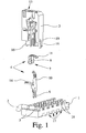
- Fig. 1 shows an exploded view of a preferred embodiment, the essential components of the terminal assembly according to the invention, comprising a lower part 1, which serves to receive a device-side cable 2, an upper part 3 for receiving a - not shown here - connection side cable and a contact body 4, by an electrical connection between the device-side cable 2 and the connection-side cable is made.
- fastening means 5 are further formed, with which the device-side cable 2 can be fixed to or in the lower part 1. The attachment of the device-side cable 2 in the lower part 1 by means of the fastening means 5 takes place without electrical contact of the device-side cable. 2
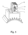
- the contact body 4 is assigned to the upper part 3 and fixed functionally in the upper part 3 in its installation position, which is shown in FIGS. 3, 5, 7 and 9.
- the contact body 4 is arranged in the upper part 3, that the contact body 4 contacted with a first contact means 6 attached in the lower part 1 device side cable 2 in the joining position of the lower part 1 with the upper part 3.
- the joining position of the lower part 1 and the upper part 3 is again shown in FIGS. 3, 5, 7 and 9.
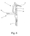
- the contact body 4 has a second contact means 7, 8, via which the connection-side cable to the contact body 4 is electrically connectable and mechanically sufficiently fastened to the contact body 4, so that the electrical connection is ensured even under certain Auszug theory on the connection side cable.
- the first contact means 6 is designed as a cutting contact.
- the particular advantage of using a trained as a cutting contact first contact means 6 is just in connection with the terminal arrangement according to the invention is that the device-side cable 2 must not be exposed for contacting, so that the handling of the device-side cable 2 in its attachment to the Lower part 1 of the connection arrangement with the fastening means 5 is safely possible.
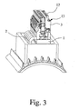
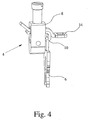
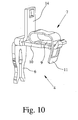
- the second contact means 7, 8 of the contact body 4 can in principle be configured in any desired manner. Illustrated are in FIGS. 1 and 5 to 10 each embodiment using spring clamps 7 and in Figs. 3 and 4 an embodiment using a screw 8 as a second contact means.
- the electrical connection arrangement according to the invention is not limited to these variants, but other connection techniques can be used.
- the spring terminals 7 are configured in a known manner as a loop-shaped tension springs, with a plant leg 9 for contact with a busbar 10 and with a spring leg 11, the free end is angled in the direction of plant leg 9, wherein the free end of the abutment leg 9 passes through an opening in the spring leg 11 movable.
- Figures 1, 5, 6, 9 and 10 show embodiments in which the spring leg 11 of the spring-loaded terminals 7 faces the insertion direction of the connection-side cable.
- the spring terminal is shown in each case in its deflected, open position, which can be caused by external force, for example by pressing the spring terminal 7 with an operating tool. The operating tool is thereby brought in the usual way via an actuating opening in the upper part 3 of the terminal assembly to the spring terminal 7.
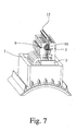
- the loop-shaped bent spring terminal 7 is arranged with its spring leg 11 facing away from the insertion direction of the connection-side cable in the upper part 3 of the connection arrangement.
- the operating principle is comparable to that of the previously described spring-loaded terminals 7, but the design of the spring-loaded terminal 7 according to FIGS. 7 and 8 permits a more compact design of the upper part 3 than is possible in the previously described embodiments.
- the spring clamp is designed as a U-shaped pawl spring in which the festzuklemmende conductor is pressed by the free end of a spring leg against a busbar and locks the conductor in the extension direction.
- the contact body 4 is not stretched substantially rectilinear as in the other illustrated embodiments, but the plant leg 9 of the spring terminal 7 and the busbar 10 are arranged opposite to the first contact means 6 substantially at right angles angled an overall flatter construction - measured from the bottom 1 of the terminal assembly is achieved.
- the contact body 4 is always formed so that it can receive a leg of a jumper 12.
- the contact body 4 in the embodiments of FIGS. 1 6 and 10 are each formed so that a contact leg 14 is formed on it, which serves an opening for receiving a preferably elastically or conically shaped leg of a jumper 12.
- the contact leg 14 is not formed on the contact body 4, but inserted into the screw 8 of the contact body 4, wherein a secure contact between the screw 8, the busbar 10 and the contact leg 14 by tightening the Screw terminal 8 is produced.
- a recess 13 is formed in the upper part 3 of the terminal assembly for receiving the jumper 12 is. On the one hand, this reduces or eliminates the risk of unwanted electrical contact with the conductive parts of the jumper 12 and, on the other hand, minimizes the risk of accidental removal of the jumper 12 from the upper part 3 of the terminal arrangement.
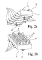
- Figures 2a and 2b illustrate the lower part 1 of the terminal assembly separately.
- the fixing of the device-side cable 2 serving fastening means 5 in the lower part 1 is here each formed as a pair of brackets.
- the fastening means 5 is formed in the lower part 1 and insofar consists of the same isolierrichen material as the entire lower part 1.
- a particularly good attachment of the device-side cable 2 by the fastener 5 is achieved when the lower part 1 in the region of Cable receptacle is formed trough-like, so that the device-side cable 2 not only flat on the lower part 1 rests, but at least partially surrounded by the lower part 1.
- the fastening means 5 designed as a clamp are so elastic that the device-side cable 2 to be fixed by them can be pressed into the fastening means 5 without tools.
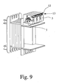
- All illustrated embodiments of the terminal arrangement according to the invention show a modular shell 3, which consists of several shell segments, which are like a disk next to each other.
- each upper part segment has a contact body 4.
- the individual upper part segments can be fastened together, for example by a fixing rod, not shown, which is guided by corresponding holes in the upper part segments of the upper part.
- the fixation is produced by corresponding wedges and grooves or by corresponding latching pins and latching recesses which are provided on the sides of each upper part segment and can be connected to one another via the adjacent upper part segments to form a block.
- the lower part 1 of the connection arrangement furthermore has further fastening means 15 with the aid of which the lower part 1 is attached to a Mounting surface is fastened.
- the further fastening means 15 is configured as a latching bolt, which can be inserted into a mounting wall in a fixed manner.
- the further fastening means 15 in at least one screw receptacle - through hole - or a DIN rail receptacle for securing the electrical connection assembly to a DIN rail.
- the illustrated and described embodiments of the electrical connection arrangement all have the advantage of a particularly simple and safe electrical connection of electrical equipment, due to the arrangement of the contact body 4 in the upper part 3 of the terminal assembly and the achievable thereby contacting the contact body 4 with the device-side cable. 2 when assembling the lower part 1 and the upper part. 3
- connection arrangement according to FIG. 1 is furthermore designed so that the lower part 1 and the upper part 3 have corresponding guide means 18, 19 which force a selective joining movement of the upper part 3 relative to the lower part 1 during assembly, so that a secure contacting of the in the Lower part 1 fixed device-side cable 2 is ensured by designed as a cutting contact contact means 6 of the contact body 4.
- the guide means 18, 19 may also be formed as a guide pin and guide pin receptacle.
- the latching connection 16, 17 at the same time assume the function of the guide means 18, 19.
- the lower part 1 of the terminal arrangement is designed in the illustrated embodiments so that it can accommodate a total of six upper segments, whereby in particular the connection of three-phase motors is advantageously possible.
Landscapes
- Connections Arranged To Contact A Plurality Of Conductors (AREA)
- Details Of Connecting Devices For Male And Female Coupling (AREA)
- Motor Or Generator Frames (AREA)
Applications Claiming Priority (1)
| Application Number | Priority Date | Filing Date | Title |
|---|---|---|---|
| DE102005041778A DE102005041778A1 (de) | 2005-09-01 | 2005-09-01 | Elektrische Anschlußanordnung |
Publications (3)
| Publication Number | Publication Date |
|---|---|
| EP1760834A2 true EP1760834A2 (fr) | 2007-03-07 |
| EP1760834A3 EP1760834A3 (fr) | 2010-05-05 |
| EP1760834B1 EP1760834B1 (fr) | 2014-12-03 |
Family
ID=37460018
Family Applications (1)
| Application Number | Title | Priority Date | Filing Date |
|---|---|---|---|
| EP06016756.6A Active EP1760834B1 (fr) | 2005-09-01 | 2006-08-11 | Assemblage de bornes électriques |
Country Status (4)
| Country | Link |
|---|---|
| US (1) | US7252534B2 (fr) |
| EP (1) | EP1760834B1 (fr) |
| CN (1) | CN1941508B (fr) |
| DE (1) | DE102005041778A1 (fr) |
Cited By (1)
| Publication number | Priority date | Publication date | Assignee | Title |
|---|---|---|---|---|
| FR3020507A1 (fr) * | 2014-04-29 | 2015-10-30 | Abb France | Connecteur debrochable |
Families Citing this family (22)
| Publication number | Priority date | Publication date | Assignee | Title |
|---|---|---|---|---|
| US7384317B1 (en) * | 2006-12-21 | 2008-06-10 | General Electric Company | Multi-terminal block for electronic devices having superimposed conductor connecting levels |
| DE102007022806B3 (de) * | 2007-05-11 | 2008-11-27 | Wago Verwaltungsgesellschaft Mbh | Klemmenbauteil |
| DE102007035016A1 (de) * | 2007-07-26 | 2009-01-29 | Abb Ag | Schraubanschlussklemme und Verfahren zu deren Herstellung |
| US7491098B1 (en) * | 2007-10-10 | 2009-02-17 | General Electric Company | Screwless terminal for electrical leads |
| DE102008025433B4 (de) * | 2008-02-29 | 2011-01-13 | Phoenix Contact Gmbh & Co. Kg | Klemmenanschlußblock |
| DE102008025432A1 (de) * | 2008-02-29 | 2009-09-10 | Phoenix Contact Gmbh & Co. Kg | KLemmenanschlußblock |
| DE102008050322B4 (de) * | 2008-10-04 | 2021-07-15 | Te Connectivity Germany Gmbh | Elektromotor-Anschluss sowie Elektromotor |
| DE102010009805B4 (de) * | 2010-03-01 | 2013-02-14 | Phoenix Contact Gmbh & Co. Kg | Steckbrücke |
| US7988486B1 (en) * | 2010-06-09 | 2011-08-02 | K.S. Terminals Inc. | Junction box and conductive terminals therein |
| US8951064B2 (en) | 2010-12-14 | 2015-02-10 | Ideal Industries, Inc. | Terminal structures for wiring devices |
| DE102010063978A1 (de) * | 2010-12-22 | 2012-06-28 | Beckhoff Automation Gmbh | Verbindungsmodul und Verbindungssystem |
| US8795006B2 (en) * | 2012-10-16 | 2014-08-05 | Leviton Manufacturing Co., Inc. | Reconfigurable electrical terminal with multiple configurations employing a clamp and a fastener |
| CN103001024A (zh) * | 2012-12-04 | 2013-03-27 | 上海友邦电气(集团)股份有限公司 | 一种用于低压电器接线模块的笼式弹簧卡紧模块 |
| JP6557021B2 (ja) * | 2015-02-17 | 2019-08-07 | スリーエム イノベイティブ プロパティズ カンパニー | コネクタ、及びコネクタアセンブリ |
| DE102015107853B4 (de) * | 2015-05-19 | 2020-08-13 | Wago Verwaltungsgesellschaft Mbh | Leiteranschlussklemme |
| DE102016107482A1 (de) * | 2016-04-22 | 2017-10-26 | Phoenix Contact Gmbh & Co. Kg | Steckkontakt |
| DE102016111627A1 (de) | 2016-06-24 | 2017-12-28 | Wago Verwaltungsgesellschaft Mbh | Leiteranschlussklemme |
| DE102016224526A1 (de) * | 2016-12-08 | 2018-06-14 | Brose Fahrzeugteile GmbH & Co. Kommanditgesellschaft, Würzburg | Stator einer elektrischen Maschine, elektrische Maschine sowie Verlege- und Kontakteinrichtung für eine elektrische Maschine |
| BE1025936B1 (de) * | 2018-01-22 | 2019-08-21 | Phoenix Contact Gmbh & Co Kg | Baukastensystem zum Herstellen eines elektrischen Geräts |
| DE102018120749A1 (de) * | 2018-07-24 | 2020-01-30 | Tdk Electronics Ag | Anschluss für ein elektronisches leistungsbauteil und elektronisches leistungsbauteil |
| CN109286091B (zh) * | 2018-08-23 | 2021-01-08 | 广州市昊志机电股份有限公司 | 用于直线电机的接线装置、直线电机及直线电机系统 |
| DE102022126516A1 (de) * | 2022-10-12 | 2024-04-18 | Schaeffler Technologies AG & Co. KG | Stator |
Citations (3)
| Publication number | Priority date | Publication date | Assignee | Title |
|---|---|---|---|---|
| US4262985A (en) | 1979-03-26 | 1981-04-21 | Bell Telephone Laboratories, Incorporated | Connector for plural conductors |
| DE10201495A1 (de) | 2002-01-17 | 2003-08-14 | Wieland Electric Gmbh | Elektrische Anschlussklemme |
| DE10232281A1 (de) | 2002-07-16 | 2004-02-12 | Phoenix Contact Gmbh & Co. Kg | Elektrische Anschlußanordnung |
Family Cites Families (17)
| Publication number | Priority date | Publication date | Assignee | Title |
|---|---|---|---|---|
| US4118095A (en) * | 1977-07-06 | 1978-10-03 | Bell Telephone Laboratories, Incorporated | Wire connecting block |
| FR2407578A1 (fr) * | 1977-10-26 | 1979-05-25 | Alsthom Cgee | Borne de raccordement axial |
| FR2600831B1 (fr) * | 1986-06-26 | 1988-09-16 | Mars Actel | Connecteur, notamment pour paire telephonique |
| US5147218A (en) * | 1991-04-12 | 1992-09-15 | Minnesota Mining And Manufacturing Company | Pluggable modular splicing connector and bridging adapter |
| US5281163A (en) * | 1991-09-23 | 1994-01-25 | Minnesota Mining And Manufacturing Company | Cross connect system for telecommunications systems |
| US5364288A (en) * | 1992-07-24 | 1994-11-15 | North American Philips Corporation | Electrical connecting device |
| US5498172A (en) * | 1993-07-30 | 1996-03-12 | Sunx Kabushiki Kaisha | Electrical connector for interconnecting parallel multiconductor cables |
| US5722850A (en) * | 1995-11-27 | 1998-03-03 | Molex Incorporated | Telecommunications connectors |
| DE29917852U1 (de) | 1998-10-14 | 2000-03-02 | Hoogovens Aluminium Bausysteme | Halteelement für plattenartige Bauelemente |
| FR2789525B1 (fr) * | 1999-02-05 | 2001-03-16 | Schneider Electric Sa | Appareil interrupteur electrique et ensemble a assemblage rapide |
| DE29910867U1 (de) * | 1999-06-28 | 1999-09-30 | Stocko Contact Gmbh & Co Kg | Elektrischer Kabelsteckverbinder mit Kurzschlußüberbrückung |
| DE29917825U1 (de) * | 1999-10-09 | 2001-02-22 | Weidmueller Interface | Verbindungselement mit Querverbindung |
| DE10021027B4 (de) * | 2000-05-02 | 2009-12-17 | Wago Verwaltungsgesellschaft Mbh | Elektrische Klemme |
| EP1449277B1 (fr) * | 2001-11-21 | 2007-07-25 | Woodhead Industries, Inc. | Connecteur électrique moulé |
| DE10163809B4 (de) * | 2001-12-22 | 2006-01-26 | Wieland Electric Gmbh | Anschlussklemme |
| CN2613898Y (zh) * | 2003-01-17 | 2004-04-28 | 叶圣兴 | 连接器端子 |
| DE20315898U1 (de) * | 2003-10-16 | 2005-02-24 | Weidmüller Interface GmbH & Co. KG | Anschlußklemme zum Aufsetzen auf ein Trägerelement |
-
2005
- 2005-09-01 DE DE102005041778A patent/DE102005041778A1/de not_active Ceased
-
2006
- 2006-08-11 EP EP06016756.6A patent/EP1760834B1/fr active Active
- 2006-08-31 US US11/468,885 patent/US7252534B2/en not_active Expired - Fee Related
- 2006-09-01 CN CN200610126733.5A patent/CN1941508B/zh not_active Expired - Fee Related
Patent Citations (3)
| Publication number | Priority date | Publication date | Assignee | Title |
|---|---|---|---|---|
| US4262985A (en) | 1979-03-26 | 1981-04-21 | Bell Telephone Laboratories, Incorporated | Connector for plural conductors |
| DE10201495A1 (de) | 2002-01-17 | 2003-08-14 | Wieland Electric Gmbh | Elektrische Anschlussklemme |
| DE10232281A1 (de) | 2002-07-16 | 2004-02-12 | Phoenix Contact Gmbh & Co. Kg | Elektrische Anschlußanordnung |
Non-Patent Citations (1)
| Title |
|---|
| "COMBICON - Leiterplattenanschluß", PHOENIX CONTACT PRODUKTKATALOG, January 2001 (2001-01-01), pages 198 - 212 |
Cited By (1)
| Publication number | Priority date | Publication date | Assignee | Title |
|---|---|---|---|---|
| FR3020507A1 (fr) * | 2014-04-29 | 2015-10-30 | Abb France | Connecteur debrochable |
Also Published As
| Publication number | Publication date |
|---|---|
| EP1760834A3 (fr) | 2010-05-05 |
| US20070049104A1 (en) | 2007-03-01 |
| US7252534B2 (en) | 2007-08-07 |
| CN1941508B (zh) | 2014-05-07 |
| DE102005041778A1 (de) | 2007-03-08 |
| CN1941508A (zh) | 2007-04-04 |
| EP1760834B1 (fr) | 2014-12-03 |
Similar Documents
| Publication | Publication Date | Title |
|---|---|---|
| EP1760834B1 (fr) | Assemblage de bornes électriques | |
| EP1811604B1 (fr) | Barette à bornes électriques | |
| EP2724420B1 (fr) | Borne électrique de raccordement | |
| DE102008024366B4 (de) | Durchführungsklemme | |
| DE102005050399B3 (de) | Anschlussklemme für Leiterplatten | |
| EP1507315B1 (fr) | Pont à fiche pour des borniers électriques et borniers associées | |
| EP1515397A1 (fr) | Borne de connexion électrique à raccordement enfichable directe de conducteur électrique | |
| DE19626390C2 (de) | Elektrische Klemme mit Sammelschienenanschluß | |
| DE102007016333A1 (de) | Elektrisches Reiheneinbaugerät | |
| DE4102784C2 (de) | Anschlußklemme | |
| DE10134417C1 (de) | Elektrische Anschluß- oder Verbindungseinrichtung | |
| DE102008025433B4 (de) | Klemmenanschlußblock | |
| DE202005007221U1 (de) | Befestigungseinsatz für einen Steckverbinder | |
| DE102004040859B4 (de) | Elektrische Reihenklemme und Prüfstecker zur Verwendung bei einer elektrischen Klemme | |
| DE102008025432A1 (de) | KLemmenanschlußblock | |
| EP3405998B1 (fr) | Pince crocodile à barre omnibus dotée de la technologie à ressort de serrage et procédé de réalisation d'une pince crocodile à barre omnibus | |
| DE3934981C2 (fr) | ||
| DE102018214104A1 (de) | Elektromaschine und Montageverfahren | |
| DE102006008971B4 (de) | Funktionsstecker und Baueinheit aus zwei elektrischen Reihenklemmen und einem Funktionsstecker | |
| EP1990879B1 (fr) | Support de spécification destiné à la fixation d'un relais de surcharge | |
| DE102018107604A1 (de) | Überspannungsschutzeinrichtung mit mindestens einem Überspannungsschutzgerät, bestehend aus einem Sockelteil und einem mit dem Sockelteil verbindbaren Steckteil | |
| DE102017110645A1 (de) | Anschlusseinrichtung zum Anschließen zumindest eines elektrischen Leiters an eine Bolzenklemme | |
| DE10338787A1 (de) | Querverbinder für Reihenklemmen | |
| DE4400470A1 (de) | Querverbinder zur elektrischen Verbindung einer PE-Klemme mit einer N-Klemme | |
| DE102021117232A1 (de) | Klemmenanschlussblock mit Anschlusselementen |
Legal Events
| Date | Code | Title | Description |
|---|---|---|---|
| PUAI | Public reference made under article 153(3) epc to a published international application that has entered the european phase |
Free format text: ORIGINAL CODE: 0009012 |
|
| AK | Designated contracting states |
Kind code of ref document: A2 Designated state(s): AT BE BG CH CY CZ DE DK EE ES FI FR GB GR HU IE IS IT LI LT LU LV MC NL PL PT RO SE SI SK TR |
|
| AX | Request for extension of the european patent |
Extension state: AL BA HR MK YU |
|
| PUAL | Search report despatched |
Free format text: ORIGINAL CODE: 0009013 |
|
| AK | Designated contracting states |
Kind code of ref document: A3 Designated state(s): AT BE BG CH CY CZ DE DK EE ES FI FR GB GR HU IE IS IT LI LT LU LV MC NL PL PT RO SE SI SK TR |
|
| AX | Request for extension of the european patent |
Extension state: AL BA HR MK RS |
|
| 17P | Request for examination filed |
Effective date: 20101105 |
|
| AKX | Designation fees paid |
Designated state(s): DE ES FR GB IT |
|
| 17Q | First examination report despatched |
Effective date: 20101216 |
|
| GRAP | Despatch of communication of intention to grant a patent |
Free format text: ORIGINAL CODE: EPIDOSNIGR1 |
|
| INTG | Intention to grant announced |
Effective date: 20140612 |
|
| GRAS | Grant fee paid |
Free format text: ORIGINAL CODE: EPIDOSNIGR3 |
|
| GRAA | (expected) grant |
Free format text: ORIGINAL CODE: 0009210 |
|
| AK | Designated contracting states |
Kind code of ref document: B1 Designated state(s): DE ES FR GB IT |
|
| REG | Reference to a national code |
Ref country code: GB Ref legal event code: FG4D Free format text: NOT ENGLISH |
|
| REG | Reference to a national code |
Ref country code: DE Ref legal event code: R096 Ref document number: 502006014095 Country of ref document: DE Effective date: 20150115 |
|
| PG25 | Lapsed in a contracting state [announced via postgrant information from national office to epo] |
Ref country code: ES Free format text: LAPSE BECAUSE OF FAILURE TO SUBMIT A TRANSLATION OF THE DESCRIPTION OR TO PAY THE FEE WITHIN THE PRESCRIBED TIME-LIMIT Effective date: 20141203 |
|
| REG | Reference to a national code |
Ref country code: FR Ref legal event code: PLFP Year of fee payment: 10 |
|
| REG | Reference to a national code |
Ref country code: DE Ref legal event code: R097 Ref document number: 502006014095 Country of ref document: DE |
|
| PLBE | No opposition filed within time limit |
Free format text: ORIGINAL CODE: 0009261 |
|
| STAA | Information on the status of an ep patent application or granted ep patent |
Free format text: STATUS: NO OPPOSITION FILED WITHIN TIME LIMIT |
|
| 26N | No opposition filed |
Effective date: 20150904 |
|
| GBPC | Gb: european patent ceased through non-payment of renewal fee |
Effective date: 20150811 |
|
| PG25 | Lapsed in a contracting state [announced via postgrant information from national office to epo] |
Ref country code: GB Free format text: LAPSE BECAUSE OF NON-PAYMENT OF DUE FEES Effective date: 20150811 |
|
| REG | Reference to a national code |
Ref country code: FR Ref legal event code: PLFP Year of fee payment: 11 |
|
| PGFP | Annual fee paid to national office [announced via postgrant information from national office to epo] |
Ref country code: FR Payment date: 20160825 Year of fee payment: 11 |
|
| REG | Reference to a national code |
Ref country code: FR Ref legal event code: ST Effective date: 20180430 |
|
| PG25 | Lapsed in a contracting state [announced via postgrant information from national office to epo] |
Ref country code: FR Free format text: LAPSE BECAUSE OF NON-PAYMENT OF DUE FEES Effective date: 20170831 |
|
| PGFP | Annual fee paid to national office [announced via postgrant information from national office to epo] |
Ref country code: IT Payment date: 20180823 Year of fee payment: 13 |
|
| PG25 | Lapsed in a contracting state [announced via postgrant information from national office to epo] |
Ref country code: IT Free format text: LAPSE BECAUSE OF NON-PAYMENT OF DUE FEES Effective date: 20190811 |
|
| P01 | Opt-out of the competence of the unified patent court (upc) registered |
Effective date: 20230424 |
|
| REG | Reference to a national code |
Ref country code: DE Ref legal event code: R084 Ref document number: 502006014095 Country of ref document: DE |
|
| PGFP | Annual fee paid to national office [announced via postgrant information from national office to epo] |
Ref country code: DE Payment date: 20231027 Year of fee payment: 18 |