EP1760498B1 - Lichtreflektor und oberflächenlichtquelleneinrichtung damit - Google Patents
Lichtreflektor und oberflächenlichtquelleneinrichtung damit Download PDFInfo
- Publication number
- EP1760498B1 EP1760498B1 EP05746002A EP05746002A EP1760498B1 EP 1760498 B1 EP1760498 B1 EP 1760498B1 EP 05746002 A EP05746002 A EP 05746002A EP 05746002 A EP05746002 A EP 05746002A EP 1760498 B1 EP1760498 B1 EP 1760498B1
- Authority
- EP
- European Patent Office
- Prior art keywords
- light
- light reflector
- layer
- substrate layer
- reflector
- Prior art date
- Legal status (The legal status is an assumption and is not a legal conclusion. Google has not performed a legal analysis and makes no representation as to the accuracy of the status listed.)
- Not-in-force
Links
Images
Classifications
-
- G—PHYSICS
- G02—OPTICS
- G02B—OPTICAL ELEMENTS, SYSTEMS OR APPARATUS
- G02B6/00—Light guides; Structural details of arrangements comprising light guides and other optical elements, e.g. couplings
- G02B6/0001—Light guides; Structural details of arrangements comprising light guides and other optical elements, e.g. couplings specially adapted for lighting devices or systems
- G02B6/0011—Light guides; Structural details of arrangements comprising light guides and other optical elements, e.g. couplings specially adapted for lighting devices or systems the light guides being planar or of plate-like form
- G02B6/0033—Means for improving the coupling-out of light from the light guide
- G02B6/005—Means for improving the coupling-out of light from the light guide provided by one optical element, or plurality thereof, placed on the light output side of the light guide
- G02B6/0055—Reflecting element, sheet or layer
-
- G—PHYSICS
- G02—OPTICS
- G02F—OPTICAL DEVICES OR ARRANGEMENTS FOR THE CONTROL OF LIGHT BY MODIFICATION OF THE OPTICAL PROPERTIES OF THE MEDIA OF THE ELEMENTS INVOLVED THEREIN; NON-LINEAR OPTICS; FREQUENCY-CHANGING OF LIGHT; OPTICAL LOGIC ELEMENTS; OPTICAL ANALOGUE/DIGITAL CONVERTERS
- G02F1/00—Devices or arrangements for the control of the intensity, colour, phase, polarisation or direction of light arriving from an independent light source, e.g. switching, gating or modulating; Non-linear optics
- G02F1/01—Devices or arrangements for the control of the intensity, colour, phase, polarisation or direction of light arriving from an independent light source, e.g. switching, gating or modulating; Non-linear optics for the control of the intensity, phase, polarisation or colour
- G02F1/13—Devices or arrangements for the control of the intensity, colour, phase, polarisation or direction of light arriving from an independent light source, e.g. switching, gating or modulating; Non-linear optics for the control of the intensity, phase, polarisation or colour based on liquid crystals, e.g. single liquid crystal display cells
- G02F1/133—Constructional arrangements; Operation of liquid crystal cells; Circuit arrangements
- G02F1/1333—Constructional arrangements; Manufacturing methods
- G02F1/1335—Structural association of cells with optical devices, e.g. polarisers or reflectors
- G02F1/1336—Illuminating devices
- G02F1/133602—Direct backlight
- G02F1/133605—Direct backlight including specially adapted reflectors
-
- Y—GENERAL TAGGING OF NEW TECHNOLOGICAL DEVELOPMENTS; GENERAL TAGGING OF CROSS-SECTIONAL TECHNOLOGIES SPANNING OVER SEVERAL SECTIONS OF THE IPC; TECHNICAL SUBJECTS COVERED BY FORMER USPC CROSS-REFERENCE ART COLLECTIONS [XRACs] AND DIGESTS
- Y10—TECHNICAL SUBJECTS COVERED BY FORMER USPC
- Y10T—TECHNICAL SUBJECTS COVERED BY FORMER US CLASSIFICATION
- Y10T428/00—Stock material or miscellaneous articles
- Y10T428/24—Structurally defined web or sheet [e.g., overall dimension, etc.]
- Y10T428/24355—Continuous and nonuniform or irregular surface on layer or component [e.g., roofing, etc.]
Definitions
- the present invention is useful for a light-reflective member for use in reflecting plates in planar light source devices, reflectors and various lighting instruments, and relates to a light reflector and a planar light source device that comprises the light reflector.
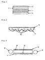
- a typical structure of an underlight-type backlight comprises a housing 11 that serves both as a profile case and as a light reflector, a diffuser sheet 14, and a light source such as a cold-cathode lamp 15, as in Fig. 2 .
- a typical structure of a sidelight-type backlight comprises a light waveguide with a dot print 12 on a transparent acrylic plate 13, a light reflector 11, a diffuser sheet 14, and a light source such as a cold-cathode lamp 15, as in Fig. 3 .
- the light from the light source is reflected on the light reflector, and forms uniform planar light though the diffuser.
- some improvements have been made in these by increasing the power of the lighting source and by increasing the number of the light source lamps therein.
- plural light sources may be disposed, as in Fig. 2 and Fig. 3 .
- white polyester films have been much used for the light reflector for the application as herein (e.g., JP-A 4-239540 ).
- a light reflector that comprises a white polyester film is often problematic in point of its discoloration (yellowing) owing to the recent increase in the quantity of light and to the increase in the ambient temperature by the heat from lamp, and materials that are less discolored have become desired.
- a light reflector comprising a white polyolefin film has been proposed (e.g., JP-A 6-298957 , 2002-31704 ).
- a white polyolefin film has also been proposed, of which the discoloration is smaller than a light reflector comprising a white polyester film (e.g., JP-A 8-262208 , 2003-176367 ).
- EP 1 424 571 and WO 03/014778 both describe a light reflector formed of a biaxially-stretched film.
- the light reflector has a surface layer B which can include particles, a substrate layer A and a back layer C which, after being laminated, have been stretched together.
- An object of the invention is to provide a light reflector having high reflectivity, which is characterized by its specific structure and has thereby attained an improvement of the brightness thereof not known by anyone till now.
- the laminate film comprises a substrate layer (A) having a function of a light-reflective layer and, provided thereon, a light-diffusive layer (B) having an intrinsic surface roughness and having a function of efficiently diffusing light, in which a light-diffusing capability is imparted to the light reflector surface and the reflectivity of the film is thereby greatly increased, and which is characterized in that its surface roughness index Z is at least 1 ⁇ m -1 , its reflectance is at least 95% and its regular reflectance is at most 3%.
- the light reflector of the invention comprises the laminate film having a light-diffusive layer (B) on one surface of a substrate layer (A), which is characterized in that the surface roughness index Z, as represented by the following formula (1), of the light-reflective surface of the light reflector is at least 1 ⁇ m -1 , that the reflectance R1 thereof at a wavelength of 550 nm is at least 95%, and that the regular reflectance R2 thereof, as represented by the following formula (2), at a wavelength of 550 nm is at most 3%:
- Surface roughness index Z surface area , Sf , of light - reflective surface / volume , V , of the projections of light - reflective surface
- Regular Reflectance R ⁇ 2 reflectance R ⁇ 1 - diffuse reflectance R ⁇ 3 wherein R3 is a diffuse reflectance at a wavelength of 550 nm.
- the scattering coefficient S is preferably at least 0.5; and the brightness is preferably at least 1430 cd/m 2
- the substrate layer (A) contains a thermoplastic resin and a filler, it is stretched in at least one direction, and its areal draw ratio is from 1.3 to 80 times.
- the filler concentration in the substrate layer (A) is from 5 to 75% by weight, and the filler is an inorganic filler having a mean particle size of from 0.05 to 1.5 ⁇ m and/or an organic filler having a mean dispersed particle size of from 0.05 to 1.5 ⁇ m.
- the filler concentration in the light-diffusive layer (B) is from 5 to 90% by weight, and the filler is an inorganic filler having a mean particle size of from 0.05 to 15 ⁇ m and/or an organic filler having a mean dispersed particle size of from 0.05 to 15 ⁇ m.
- a surface-treated inorganic filter is preferably used.
- Scattering Coefficient S 100 ⁇ R ⁇ 1 / 100 - R ⁇ 1 ⁇ T A ⁇ P wherein T A is the thickness ( ⁇ m) of the substrate layer (A); P is a porosity (%) represented by the following formula (4).
- Porosity P ⁇ ⁇ 0 - ⁇ / ⁇ ⁇ 0 x 100 wherein ⁇ 0 is the true density of the laminate film, and p indicates the density of the substrate layer A.
- the laminate film has an interlayer (C) on the face of the substrate layer (A) opposite to the face thereof having the light-diffusive layer (B) thereon; preferably, the surface strength of the face opposite to the light-reflective face thereof is at least 250 g; preferably, the surface strength of the light-reflective face thereof is at least 250 g; and preferably the thickness of the light-diffusive layer (B) is from 0.5 to 20 ⁇ m.
- the porosity P of the laminate film is from 15 to 60%; and preferably, the thermoplastic resin is a polyolefin-based resin.
- the invention further provides a planar light source device comprising the above light reflector.
- the light reflector of the invention has high reflectivity and has excellent light diffusibility.
- the planar light source device produced by the use of the light reflector of the invention has high brightness and is extremely useful.
- 1 is a substrate layer (A)
- 2 is a light-diffusive layer (B)
- 3 is an interlayer (C)
- 11 is a light reflector (housing)
- 12 is a dot print
- 13 is an acrylic plate
- 14 is a diffuser sheet
- 15 is a cold-cathode lamp.
- the numerical range expressed by the wording "a number to another number” means the range that falls between the former number indicating the lowermost limit of the range and the latter number indicating the uppermost limit thereof.
- the substrate layer (A) having a function of a light-reflective layer preferably contains a large number of pores of which the thickness is controlled to the wavelength size of visible light.
- the substrate layer (A) preferably contains a thermoplastic resin and a filler.
- thermoplastic resin for use in the substrate layer (A) in the invention is not specifically defined.
- the thermoplastic resin for use in the substrate film (A) may be any thermoplastic resin including ethylenic resins such as high-density polyethylene, middle-density polyethylene, low-density polyethylene; propylenic resins; polyolefin-based resins such as polymethyl-1-pentene, ethylene-cyclic olefin copolymer; polyamide resins such as nylon-6, nylon-6,6, nylon-6, 10, nylon-6, 12; thermoplastic polyester resins such as polyethylene terephthalate and its copolymer, polyethylene naphthalate, aliphatic polyester; and other thermoplastic resins such as polycarbonate, atactic polystyrene, syndiotactic polystyrene, polyphenylene sulfide. Two or more of these may be mixed for use herein.
- polyolefin-based resins in view of the chemical resistance and the production cost thereof; and more preferred are propylenic resins.
- the propylenic resins include propylene homopolymers, and propylene-based copolymers with ⁇ -olefin such as ethylene, 1-butene, 1-hexene, 1-heptene, 4-methyl-1-pentene.
- the stereospecificity of the resins is not specifically defined.
- the resins may be isotactic or syndiotactic, and may have any desired degree of stereospecificity.
- the copolymers may be binary, ternary or quaternary ones, and may be random copolymers or block copolymers.
- the substrate layer (A) contains from 25 to 95% by weight, more preferably from 30 to 90% by weight of such a thermoplastic resin.
- the thermoplastic resin content of at least 25% by weight in the substrate layer (A) may prevent surface scratches in stretching and forming the laminate film mentioned below, and the thermoplastic resin content of at most 95% by weight may readily provide a satisfactory degree of porosity of the film.
- filler to be in the substrate layer (A) in the invention along with the thermoplastic resin therein, usable are various inorganic fillers or organic fillers.
- the inorganic filler includes heavy calcium carbonate, precipitated calcium carbonate, calcined clay, talc, titanium oxide, barium sulfate, aluminium sulfate, silica, zinc oxide, magnesium oxide, diatomaceous earth.
- those inorganic fillers processed with various surface-treating agents are also usable herein.
- heavy calcium carbonate, precipitated calcium carbonate and their surface-treated products, and clay and diatomaceous earth are preferred as they are inexpensive and facilitate the formation of pores in stretching. More preferred are heavy calcium carbonate and precipitated calcium carbonate that have been processed with various surface-treating agents.
- Preferred examples of the surface-treating agents are, for example, resin acids, fatty acids, organic acids, sulfuric ester-type anionic surfactants, sulfonic acid-type anionic surfactants, petroleum resin acids, their sodium, potassium or ammonium salts, and their fatty acid esters, resin acid esters, wax and paraffin. Also preferred are nonionic surfactants, dienic polymers, titanate-type coupling agents, silane-type coupling agents, and phosphate-type coupling agents.
- the sulfuric ester-type anionic surfactants are, for example, long-chain alcohol sulfuric esters, polyoxyethylene alkyl ether sulfuric esters, sulfurized oils, and their sodium or potassium salts.
- the sulfonic acid-type anionic surfactants are, for example, alkylbenzenesulfonic acids, alkylnaphthalene sulfonic acids, paraffin sulfonic acids, ⁇ -olefinsulfonic acids, alkylsulfosuccinic acids, and their sodium or potassium salts.
- the fatty acids are, for example, caproic acid, caprylic acid, pelargonic acid, capric acid, undecanoic acid, lauric acid, myristic acid, palmitic acid, stearic acid, behenic acid, oleic acid, linolic acid, linolenic acid, eleostearic acid;
- the organic acids are, for example, maleic acid, sorbic acid;
- the dienic polymers are, for example, polybutadiene, isoprene;
- the nonionic surfactants are polyethylene glycol ester-type surfactants.
- One or more these surface-treating agents may be used herein either singly or as combined.
- the organic filler for use herein may have a melting point or a glass transition point (e.g., 120 to 300°C) higher than the melting point or the glass transition point of the thermoplastic resin.
- a melting point or a glass transition point e.g., 120 to 300°C
- its examples are polyethylene terephthalate, polybutylene terephthalate, polyamide, polycarbonate, polyethylene naphthalate, polystyrene, melamine resin, cyclic olefin homopolymer, copolymer of cyclic olefin and ethylene, polyethylene sulfite, polyimide, polyethyl ether ketone, polyphenylene sulfite.
- immiscible organic fillers having a higher melting point or glass transition temperature than that of the polyolefin resin used for easy pore formation.
- One of the inorganic filler or the organic filler may be selected and may be used singly in the substrate layer (A); or two or more may be selected from those fillers and may be combined to be in the substrate layer. In case where two or more fillers are combined and used, then the inorganic filler and the organic filler may be mixed and used.
- the mean particle size of the inorganic filler and the mean dispersed particle size of the organic filler may be determined, for example, according to a microtrack method, or through primary particle size observation with a scanning electronic microscope (in the invention, the mean value of the data of 100 particles is the mean particle size), or through specific surface area-based computation (in the invention, the specific surface area is measured with a powder specific area meter, Shimadzu's SS-100).
- the mean particle size of the inorganic filler and the mean dispersed particle size of the organic filler each are preferably from 0.05 to 1.5 ⁇ m, more preferably from 0.1 to 1 ⁇ m.
- the filler having a mean particle size or a mean diffused particle size of at most 1.5 ⁇ m is used, then uniform pores will be easy to form in the film.
- the filler having a mean particle size or a mean dispersed particle size of at least 0.05 ⁇ m is used, then predetermined pores will be easy to form in the film.
- the filler content of the stretched film to constitute the substrate layer (A) is preferably from 5 to 75% by weight, more preferably from 10 to 70% by weight.
- the filler content of at least 5% by weight may readily provide a satisfactory degree of porosity of the film, and the filler content of at most 75% by weight may prevent surface scratches in the film.
- the main resin that constitutes the substrate layer (A) is a propylenic resin
- a resin having a lower melting point than that of the propylenic resin such as polyethylene or ethylene/vinyl acetate may be added thereto in an amount of from 3 to 25% by weight for improving the stretchability of the film.
- the substrate layer (A) for use in the invention may have a single-layered structure or a multi-layered structure.
- the thickness of the substrate layer (A) is preferably from 30 to 1000 ⁇ m, more preferably from 40 to 400 ⁇ m, even more preferably from 50 to 300 ⁇ m.
- the light-diffusive layer (B) having a light-diffusing function preferably has many fine projections.
- the light-diffusive layer (B) may be formed only on the light-reflective face of the substrate layer (A) or on both faces thereof.
- the size of the fine projections may be generally from 0.1 to 2.5 ⁇ m, preferably from 0.2 to 1.5 ⁇ m, more preferably from 0.2 to 1.0 ⁇ m, even more preferably the wavelength size of visible light (from 0.38 to 0.78 ⁇ m).
- the inventors have found that, when a light-diffusive layer capable of efficiently diffusing and reflecting visible light is laminated on a conventional light reflector substrate to thereby increase the diffuse reflectance at around the surface of the light reflector, then the overall light reflection on the reflector can be basically increased with the result that the light reflector can have a more increased light reflectivity and can have a more increased brightness, and on the basis of these findings, the inventors have completed the invention.
- the same thermoplastic resin and the same filler as those used in the substrate layer (A) may be used.
- the size of the fine projections of the light-reflective layer (B) may be controlled depending on the particle size of the filler.
- the particle size of the filler is preferably from 0.05 to 1.5 ⁇ m, more preferably from 0.1 to 1.0 ⁇ m, even more preferably from 0.2 to 0.7 ⁇ m.
- the particle size of the filler is at least 0.05 ⁇ m, then it may facilitate the surface roughness formation and therefore the layer may readily have good light-diffusing capability.
- the layer may readily keep its good light-diffusing capability.
- a higher concentration of the filler is added to the layer within a range within which the layer may keep its surface strength, then the layer may have better light-diffusing capability.
- the filler concentration is preferably from 5 to 90% by weight, more preferably from 30 to 80% by weight, even more preferably from 45 to 70% by weight.
- the filler concentration is at least 5% by weight, then the surface roughness may be more easily formed and the layer may have better light-diffusing capability.
- it is at most 90% by weight then the layer may readily keep its surface strength to a degree not lower than a predetermined level.
- the thickness of the light-diffusive layer (B) is preferably from 0.5 to 20 ⁇ m, more preferably from 1 to 15 ⁇ m, even more preferably from 2 to 6 ⁇ m. When the thickness thereof is at least 0. 5 ⁇ m, then the layer may readily have a sufficient light-diffusing capability and may therefore readily attain a good reflectivity. When it is at most 20 ⁇ m, then the layer may hardly detract from the reflecting capability of the substrate layer and may therefore more readily prevent the reduction in the reflectivity of the reflector.
- the laminate film that constitute the light reflector of the invention may be composed of only the substrate layer (A) and the light-diffusive layer (B), or may additionally have an interlayer (C) and any other suitable material.
- the light-diffusive layer (B) may be laminated on both faces of the substrate layer (A) ; or an interlayer (C) may be disposed on the surface of the substrate layer (A) opposite to the surface thereof having the light-diffusive layer (B) thereon, or between the substrate layer (A) and the light-diffusive layer (B) .
- examples of the constitution of the laminate film are (B)/(A), (B)/(A)/(B), (B)/(A)/(C), (B)/(C)/(A), (B)/(C)/(A)/(B), (B)/(C)/(A)/(C)/(B).
- the same thermoplastic resin as in the substrate layer (A) may be used.
- the interlayer (C) may contain the above-mentioned filler, and the amount of the filler therein is preferably from 0 to 20% by weight, more preferably from 0 to 10% by weight, even more preferably from 0 to 5% by weight, still more preferably from 0 to 3% by weight.
- the thickness of the interlayer (C) is preferably at least 1 ⁇ m, more preferably from 2 to 30 ⁇ m, even more preferably from 3 to 20 ⁇ m. When the thickness thereof is at least 1 ⁇ m, then the layer may well enhance the surface strength of the light reflector and may therefore augment the workability thereof.
- the laminate film of the invention may contain fluorescent brightener, heat stabilizer, light stabilizer, dispersant, lubricant.
- the heat stabilizer may be a steric-hindered phenol-type, or phosphorus-containing, or amine-type stabilizer, and its content may be from 0.001 to 1% by weight.
- the light stabilizer may be a steric-hindered amine-type, or benzotriazole-type, or benzophenone-type light stabilizer, and its content may be from 0.001 to 1% by weight.
- the inorganic filler dispersant may be a silane-coupling agent, a higher fatty acid such as oleic acid or stearic acid, metal soap, polyacrylic acid, polymethacrylic acid or their salt, and its content may be from 0.01 to 4% by weight.
- employable is any ordinary monoaxially-stretching or biaxially-stretching method.
- a monoaxial-stretching method that comprises sheetwise extruding resin melt(s) through a single-layer or multi-layer T-die or I-die connected to a screw extruder, and then monoaxially stretching the resulting sheet in a mode of machine-direction stretching to be attained by utilizing the peripheral speed difference between multiple rolls; or a biaxial-stretching method that comprises a combination of the same step as in the monoaxial-stretching method and an additional step of cross-direction stretching to be attained in a tenter oven; or a simultaneous biaxial-stretching method to be attained by a combination of a tenter oven and a linear motor.
- the laminate film comprising the substrate layer (A) and the light-diffusive layer (B)
- employable is a method of coextruding a melt material for the light-diffusive layer (B) through a multi-layer T-die or I-die onto the substrate layer (A) before stretching it, and then stretching the resulting laminate;
- the substrate layer (A) is a biaxially-stretched one, a method that comprises extruding a melt material for the light-diffusive layer (B) onto the layer (A) that has been monoaxially stretched and sticking it to the latter, and then monoaxially stretching the resulting laminate; or a method that comprises stretching the substrate layer (A), then extruding a resin material for the light-diffusive layer (B) onto the layer and sticking it thereto directly or via an adhesive layer therebetween.
- the interlayer (C) is formed, then the same may apply thereto.
- the stretching temperature may be lower by 2 to 60°C than the melting point of the thermoplastic resin used, but is higher by 2 to 60°C than the glass transition point of the resin.
- the resin is propylene homopolymer (melting point, 155 to 167°C)
- the stretching temperature preferably falls between 95 and 165°C.
- the resin is polyethylene terephthalate (glass transition point: about 70°C)
- the stretching temperature preferably falls between 100 and 130°C.
- the pulling rate for the stretching preferably falls between 20 and 350 m/min.
- the obtained laminate film may be optionally heat-treated (annealed) for promoting the crystallization thereof and for reducing the thermal shrinkage of the laminate film.
- the areal draw ratio of the substrate layer (A) preferably falls between 1.3 and 80 times, more preferably between 7 and 70 times, even more preferably between 22 and 65 times, most preferably between 25 and 60 times.
- the areal draw ratio falling between 1.3 and 80 times readily forms fine pores in the film, not lowering the reflectivity of the film.
- the degree of porosity of the film is preferably from 15 to 60%, more preferably from 20 to 55%.
- the "porosity" as referred to herein is meant to indicate the value calculated according to the above-mentioned formula (4).
- ⁇ 0 indicates the true density
- p indicates the density (JIS P-8118). So far as the unstretched material does not contain much air, the true density is nearly equal to the density of the unstretched film.
- the density of the laminate film for use in the invention generally falls between 0.5 and 1.2 g/cm 3 Films having more pores have a smaller density and have a larger porosity. Films having a larger porosity may have improved surface-reflecting characteristics.
- the light reflector of the invention comprises the above-mentioned laminate film.
- the surface roughness index, Z, of the light reflector of the invention is at least 1 ⁇ m -1 , preferably from 1 to 1000, more preferably from 2 to 100, even more preferably from 3 to 10.
- the surface roughness index Z indicates the degree of surface projections, and it is proportional to the number of fine projections per a unit area of the light reflector. When the surface roughness Z is less than 1 ⁇ m -1 , then it is unfavorable since the regular reflectance tends to be high and the reflectivity tends to lower and since the brightness in planar light source devices lowers.
- a method adding a filler of which the particle size is near to the wavelength size (0.38 to 0.78 ⁇ m) of visible light to the light-diffusive layer (B) and stretching the film.
- the reflectance, R1 measured at a wavelength of 550 nm is at least 95%, preferably at least 97%, more preferably from 98% to 100%.
- the regular reflectance, R2 is at most 3%, preferably at most 2.5%, more preferably from 0% to 2%. When the reflectance is less than 95%, then it is unfavorable since the brightness in planar light source devices is low. When the regular reflectance, R2 is more than 3%, it is also unfavorable since the reflectance R1 tends to lower and the brightness in planar light source devices is low.
- R1 at least 95%, for example, employable is a method of adding a filler of which the particle size is near to the wavelength size (0.38 to 0.78 ⁇ m) of visible light to the substrate layer (A) and then stretching the film to thereby form a large number of pores having a thickness near to the wavelength size of visible light, or a method of adding a high-concentration filler with a high refractive index, of which the particle size is near to the wavelength size of visible light, to the substrate layer (A), as the light reflector may readily have the intended microstructure and its producibility is good.
- the light reflector of the invention has a scattering coefficient S, as defined by formula (3), of at least 0.5, preferably from 0. 6 to 100, more preferably from 0.8 to 50.
- the scattering coefficient, S means a degree of light scattering per a unit volume of pores, and is proportional to R1 and inversely proportional to the thickness T A and the porosity P of the substrate layer (A). According to the invention, a number of flat pores that are finer and have a more uniform size may be formed in the substrate layer (A), and therefore the light reflector can have the intended brightness not requiring any unnecessary increase in the thickness of the substrate layer (A).
- the brightness of the light reflector may be determined according to the method mentioned hereinunder.
- the brightness of the light reflector of the invention is preferably at least 1430 cd/m 2 , more preferably at least 1450 cd/m 2 ; even more preferably from 1460 cd/m 2 to 3000 cd/m 2 , still more preferably from 1470 cd/m 2 to 2000 cd/m 2 .
- the surface strength of the face (non-reflecting face) opposite to the light-reflective face thereof is at least 250 g, preferably from 270 to 1000 g.
- the surface strength of the light-reflective face of the light reflector is preferably at least 250 g, more preferably from 270 to 1000 g.
- the surface strength is less than 250 g, the surface of the light reflector may be readily scratched when it is handled thereby often causing a problem of surface fracture, etc.
- the surface strength as referred to in this description means the peeling load that is determined by sticking an adhesive tape having a width of 18 mm to the test surface of the light reflector and peeling it at a speed of 300 mm/min, as shown by the determination method mentioned below.
- the light reflector of the invention having a surface strength of at least 250 g is free from a problem of loosing or peeling thereof when it is stuck to a tabular material and shaped and worked variously.
- the shape of the light reflector of the invention is not specifically defined, and may be suitably determined in accordance with the use, the object and the service condition thereof. In general, it is used as a plate or film, but may be used in any other form capable of serving as a light reflector, and any and every form that serves as a light reflector falls within the scope of the invention.
- the light reflector of the invention may be built in a planar light source device.
- the concrete structure of the planar light source device of the invention is not specifically defined.
- One typical structure of the planar light source device comprises at least a light source, a light waveguide and a light reflector, and preferably has a diffuser sheet.
- an underlight-type backlight as in Fig. 2
- a sidelight-type backlight as in Fig. 3
- the light reflector of the invention is extremely useful as that for constituting a sidelight-type backlight.
- the light having passed through the light waveguide may be uniformly reflected by the light reflector therein with no trouble of uneven brightness in the plane direction of the device. Accordingly, the backlight device of the type gives light of a natural feel to viewers.
- the planar light source device of the invention may be effectively disposed in liquid-crystal displays, etc. When used in liquid-crystal displays, it ensures good image quality and brightness for a long period of time.
- the light reflector of the invention may be used not only in such planar light source devices as above but also in any other power-saving display devices which are not equipped with a built-in light source and in which room light is intended to reflect on the light reflector. In addition, it may be widely utilized for the back of indoor or outdoor lighting devices and for the back of decorative illumination signboards.
- composition (A), a composition (B) and a composition (C) prepared by mixing the ingredients shown in Table 1 in the ratio shown in Table 2 were separately melt-kneaded in different extruders at 250°C. Next, these were fed to one co-extrusion die, in which (B) was laminated on the surface of (A) and (C) was on the back of (A), and sheetwise extruded out and cooled to about 60°C with a chill roll to obtain a laminate of B/A/C.
- the laminate was re-heated at 145°C, then stretched in the machine direction thereof by utilizing the peripheral speed difference between a number of rolls, again re-heated up to about 150°C, and stretched in the cross direction thereof in a tenter. Then, the laminate was re-heated at 160°C and stretched in the cross direction thereof in a tenter. Next, this was annealed at 160°C and then cooled to 60°C, and its edges were trimmed away to give a three-layered laminate film. The laminate film is used as a light reflector.
- the substrate layer (A) was re-heated at 145°C, and then stretched in the machine direction to the draw ratio as in Table 2, by utilizing the peripheral speed difference between a number of rolls.
- compositions (B) and (C) prepared by mixing the ingredients shown in Table 1 in the ratio shown in Table 2 were melt-kneaded, and extruded out onto both faces of the substrate layer (A) to form a light-diffusive layer (B) and an interlayer (C) thereon, thereby giving a laminate of B/C/A/C. Then, the laminate was re-heated at 160°C and stretched in the cross direction to the draw ratio as in Table 2, in a tenter. Next, this was annealed at 160°C and then cooled to 60°C, and its edges were trimmed away to give a four-layered laminate film having a thickness as in Table 2 ( Fig. 1 ) . The laminate film is used as a light reflector.
- a light reflector was obtained in the same manner as in Example 2, for which, however, the ingredients in Table 1 were mixed in the ratio as in Table 2.
- the substrate layer (A) was re-heated at 145°C, and then stretched in the machine direction to the draw ratio as in Table 2, by utilizing the peripheral speed difference between a number of rolls.
- a composition (C) prepared by mixing the ingredients shown in Table 1 in the ratio shown in Table 2 was melt-kneaded, and extruded out onto both faces of the substrate layer (A) to an interlayer (C) thereon, thereby giving a laminate of C/A/C. Then, the laminate was re-heated at 160°C and stretched in the cross direction to the draw ratio as in Table 2, in a tenter. Next, this was annealed at 160°C and then cooled to 60°C, and its edges were trimmed away to give a three-layered laminate film having a thickness as in Table 2. The laminate film is used as a light reflector.
- Example 5 in JP-A 2002-031704 is used as a light reflector.
- the light reflector is set at the position 11 of the 14-inches-size planar light source device illustrated in Fig. 3 , and an inverter unit by Harrison is connected to the cold-cathode lamp 15.
- a tubular current of 6 mA at 12 V is applied to the cold-cathode lamp 15, and the device is switched on for lighting. After 3 hours, this is evaluated in the following matter.
- a brightness meter by Topcon (trade name, BM-7) is used for measuring the brightness.
- the distance between the part at which the brightness is determined and the planar light source device relative to the normal line direction of the planar light source device is 50 cm.
- the brightness is measured at 9 points in all, and the data are averaged.
Claims (13)
- Ein Lichtreflektor, der einen Laminatfilm mit einer Licht-diffusiven Schicht (B) auf einer Oberfläche einer Trägerschicht (A) aufweist, wobei:deren Reflexionsvermögen R1 bei einer Wellenlänge von 550 nm mindestens 95% beträgt, undderen normales Reflexionsvermögen R2, gemäß der folgenden Formel (2), bei einer Wellenlänge von 550 nm höchstens 3% beträgt:

wobei R3 eine diffusives Reflexionsvermögen bei einer Wellenlänge von 550 nm darstellt, dadurch gekennzeichnet, dass
die Licht-diffusive Schicht (B) feine Erhebungen hat und anorganische Füllstoffe mit einer Partikelgröße von 0,2 bis 0,7 µm in einer Menge von 5 bis 90 Gew.% aufweist, welche die Größe der Erhebungen kontrollieren,
der Oberflächenrauhigkeitsindex Z der Seite der Licht-diffusiven Schicht (B) des Lichtreflektors, gemäß der folgenden Formel (1), mindestens 1 µm-1 beträgt, wobei
- Der Lichtreflektor nach Anspruch 1, wobei der Streukoeffizient S der Lichtreflektierenden Oberfläche, gemäß der folgenden Formel (3), mindestens 0,5 µm-1 beträgt:

wobei TA die Dicke (µm) der Substratschicht (A) ist; P eine Porosität des Laminatfilms (%) gemäß der folgenden Formel (4) darstellt
wobei ρ0 die tatsächliche Dichte des Laminatfilms ist; und p die Dichte der Substratschicht A bezeichnet. - Der Lichtreflektor nach Anspruch 1 oder 2, wobei dieser eine Helligkeit von mindestens 1430 cd/m2 aufweist.
- Der Lichtreflektor nach einem der Ansprüche 1 bis 3, wobei die Substratschicht (A) ein thermoplastisches Harz und einen Füllstoff aufweist, und in mindestens eine Richtung gestreckt ist, und ihre Streckverhältnis von 1,3 bis 80 mal beträgt..
- Der Lichtreflektor nach einem der Ansprüche 1 bis 4, wobei die Substratschicht (A) einen anorganischen Füllstoff mit einer mittleren Partikelgröße von 0,05 bis 1,5 µm und/oder einen organischen Füllstoff mit einer mittleren dispergierten Teilchengröße von 0,05 bis 1,5 µm aufweist und die Füllstoff-Konzentration in der Substrat-Schicht (A) von 5 bis 75 Gew% aufweist.
- Der Lichtreflektor nach einem der Ansprüche 1 bis 5, wobei die Substratschicht (A) und/oder die Licht-diffusive Schicht (B) einen oberflächenbehandelten anorganischen Füllstoff aufweist.
- Der Lichtreflektor nach einem der Ansprüche 1 bis 6, wobei der Laminatfilm eine Zwischenschicht (C) auf der Fläche aufweist, welche der Fläche gegenüberliegt, welche die Licht-diffusive Schicht (B) aufweist.
- Der Lichtreflektor nach einem der Ansprüche 1 bis 7, wobei die Oberflächenfestigkeit der Fläche, die gegenüber der lichtreflektierenden Fläche des Laminatfilms liegt, mindestens 250 g beträgt.
- Der Lichtreflektor nach einem der Ansprüche1 bis 8, wobei die Oberflächenfestigkeit der Licht-reflektierenden Fläche des Laminatfilms mindestens 250 g beträgt.
- Der Lichtreflektor nach einem der Ansprüche 1 bis 9, wobei die Dicke der Licht-diffusiven Schicht (B) von 0,5 bis 20 µm beträgt.
- Der Lichtreflektor nach einem der Ansprüche 1 bis 10, wobei die Porosität P des Laminatfilms von 15 bis 60% ist.
- Der Lichtreflektor nach einem der Ansprüche 1 bis 11, wobei das thermoplastische Harz ein auf Polyolefin basierendes Harz ist.
- Eine planare Lichtquellenvorrichtung mit einem Lichtreflektor nach einem der Ansprüche 1 bis 12.
Applications Claiming Priority (2)
| Application Number | Priority Date | Filing Date | Title |
|---|---|---|---|
| JP2004161465 | 2004-05-31 | ||
| PCT/JP2005/010304 WO2005116699A1 (ja) | 2004-05-31 | 2005-05-31 | 光反射体およびそれを用いた面光源装置 |
Publications (3)
| Publication Number | Publication Date |
|---|---|
| EP1760498A1 EP1760498A1 (de) | 2007-03-07 |
| EP1760498A4 EP1760498A4 (de) | 2010-08-04 |
| EP1760498B1 true EP1760498B1 (de) | 2012-11-28 |
Family
ID=35451009
Family Applications (1)
| Application Number | Title | Priority Date | Filing Date |
|---|---|---|---|
| EP05746002A Not-in-force EP1760498B1 (de) | 2004-05-31 | 2005-05-31 | Lichtreflektor und oberflächenlichtquelleneinrichtung damit |
Country Status (6)
| Country | Link |
|---|---|
| US (1) | US7548372B2 (de) |
| EP (1) | EP1760498B1 (de) |
| KR (1) | KR101123479B1 (de) |
| CN (1) | CN100541238C (de) |
| TW (1) | TW200608113A (de) |
| WO (1) | WO2005116699A1 (de) |
Families Citing this family (14)
| Publication number | Priority date | Publication date | Assignee | Title |
|---|---|---|---|---|
| EP1837686A4 (de) * | 2004-12-17 | 2009-11-18 | Yupo Corp | Lichtreflektor und oberflächenlichtquelleneinrichtung |
| CN101416077B (zh) * | 2006-03-31 | 2011-08-24 | 东洋纺织株式会社 | 光扩散性薄膜 |
| CN102269831B (zh) | 2006-10-27 | 2013-09-18 | 东丽株式会社 | 光反射板用白色聚酯膜 |
| KR100880724B1 (ko) * | 2007-03-14 | 2009-02-02 | 제일모직주식회사 | 광확산 물질을 포함하는 액정표시장치용 도광판 및 이를이용한 액정표시장치 백라이트 유닛 |
| TWI382203B (zh) * | 2007-05-31 | 2013-01-11 | Chi Mei Corp | Light diffusion laminated board |
| KR20090009107A (ko) * | 2007-07-19 | 2009-01-22 | 도레이 카부시키가이샤 | 백색 폴리에스테르필름 |
| KR100912262B1 (ko) * | 2007-08-28 | 2009-08-17 | 제일모직주식회사 | 균일한 표면 거칠기를 가지는 광확산 필름 및 그 제조방법 |
| KR100963674B1 (ko) | 2007-12-05 | 2010-06-15 | 제일모직주식회사 | 균일한 표면 거칠기 및 저 리타데이션 값을 가지는 광확산필름 및 그 제조방법 |
| WO2009152460A1 (en) * | 2008-06-13 | 2009-12-17 | Toray Plastics (America), Inc. | Matte biaxially oriented polylactic acid film |
| EP2317350A4 (de) * | 2008-07-24 | 2012-09-26 | Yupo Corp | Lichtreflektor und ebene beleuchtungsquelle sowie beleuchtungsvorrichtung mit dem lichtreflektor |
| KR101640270B1 (ko) * | 2008-12-22 | 2016-07-15 | 가부시키가이샤 유포 코포레숀 | 광 반사체 및 면광원 장치 |
| CN103003067B (zh) * | 2010-07-16 | 2015-03-04 | 三菱树脂株式会社 | 反射材料 |
| JP5805951B2 (ja) * | 2010-07-16 | 2015-11-10 | 三菱樹脂株式会社 | 反射材 |
| KR102538884B1 (ko) * | 2017-03-31 | 2023-06-01 | 도레이 카부시키가이샤 | 트레이형상을 갖는 반사판 |
Family Cites Families (19)
| Publication number | Priority date | Publication date | Assignee | Title |
|---|---|---|---|---|
| JPH0816175B2 (ja) | 1991-01-22 | 1996-02-21 | 東レ株式会社 | 液晶ディスプレイ反射板用白色ポリエステルフイルム |
| DE69219371T3 (de) * | 1991-01-22 | 2003-04-17 | Toray Industries | Reflektor für flächenartige Lichtquelle |
| JP3067856B2 (ja) | 1991-08-09 | 2000-07-24 | 丸尾カルシウム株式会社 | 表面処理炭酸カルシウム及びその製造方法 |
| JP2745033B2 (ja) | 1991-11-12 | 1998-04-28 | 丸尾カルシウム株式会社 | 炭酸カルシウムの表面処理方法 |
| JPH06298957A (ja) | 1993-04-12 | 1994-10-25 | Mitsui Toatsu Chem Inc | 光反射シート |
| JPH07300568A (ja) | 1994-05-02 | 1995-11-14 | Fuaimatetsuku:Kk | 無機微粉体の製造方法 |
| JP3683965B2 (ja) | 1995-01-27 | 2005-08-17 | 三井化学株式会社 | 光反射体及びそれを用いた光反射装置 |
| JP3960644B2 (ja) | 1996-12-17 | 2007-08-15 | 株式会社ファイマテック | 帯電防止性無機フィラー、該フィラーを含有する樹脂組成物及びその製造方法 |
| JPH11256144A (ja) | 1998-03-11 | 1999-09-21 | Mitsubishi Paper Mills Ltd | 帯電防止剤および帯電防止性フィラー |
| JP3685031B2 (ja) | 1998-04-10 | 2005-08-17 | 丸尾カルシウム株式会社 | 合成樹脂用表面処理炭酸カルシウム填料、その製造方法、並びに該填料を配合してなる樹脂組成物 |
| JP3151196B2 (ja) | 1998-04-10 | 2001-04-03 | 丸尾カルシウム株式会社 | 表面処理炭酸カルシウム填料、その製造方法、並びに該填料を配合してなる樹脂組成物 |
| JP4688339B2 (ja) | 2000-04-26 | 2011-05-25 | 株式会社ユポ・コーポレーション | 光反射体 |
| JP2001350004A (ja) | 2000-06-08 | 2001-12-21 | Mitsui Chemicals Inc | 反射シート |
| TW527507B (en) * | 2000-07-12 | 2003-04-11 | Toray Industries | White film for surface light source |
| JP2002196117A (ja) * | 2000-12-25 | 2002-07-10 | Nitto Denko Corp | 光拡散層、光拡散性シート及び光学素子 |
| JP2002220547A (ja) | 2001-01-29 | 2002-08-09 | Maruo Calcium Co Ltd | 表面処理連鎖状炭酸カルシウム及びこれを配合してなる樹脂組成物 |
| JP3897543B2 (ja) | 2001-06-01 | 2007-03-28 | 丸尾カルシウム株式会社 | 樹脂用表面処理無機フィラー及びこれを配合した樹脂組成物 |
| JP4263882B2 (ja) | 2001-08-06 | 2009-05-13 | 株式会社ユポ・コーポレーション | 光反射体 |
| EP1424571A4 (de) * | 2001-08-06 | 2008-10-29 | Yupo Corp | Lichtreflektor |
-
2005
- 2005-05-31 WO PCT/JP2005/010304 patent/WO2005116699A1/ja active Application Filing
- 2005-05-31 TW TW094117867A patent/TW200608113A/zh unknown
- 2005-05-31 EP EP05746002A patent/EP1760498B1/de not_active Not-in-force
- 2005-05-31 CN CNB200580017780XA patent/CN100541238C/zh active Active
- 2005-05-31 US US11/628,075 patent/US7548372B2/en active Active
- 2005-05-31 KR KR1020067026914A patent/KR101123479B1/ko active IP Right Grant
Also Published As
| Publication number | Publication date |
|---|---|
| US20080259473A1 (en) | 2008-10-23 |
| KR20070044403A (ko) | 2007-04-27 |
| TWI354162B (de) | 2011-12-11 |
| KR101123479B1 (ko) | 2012-03-28 |
| EP1760498A4 (de) | 2010-08-04 |
| US7548372B2 (en) | 2009-06-16 |
| CN100541238C (zh) | 2009-09-16 |
| CN1985192A (zh) | 2007-06-20 |
| WO2005116699A1 (ja) | 2005-12-08 |
| EP1760498A1 (de) | 2007-03-07 |
| TW200608113A (en) | 2006-03-01 |
Similar Documents
| Publication | Publication Date | Title |
|---|---|---|
| EP1760498B1 (de) | Lichtreflektor und oberflächenlichtquelleneinrichtung damit | |
| EP1837686A1 (de) | Lichtreflektor und oberflächenlichtquelleneinrichtung | |
| KR100885608B1 (ko) | 다층구조 광확산판 및 그를 포함하는 액정 디스플레이 장치 | |
| EP1424571A1 (de) | Lichtreflektor | |
| JP4933060B2 (ja) | 光反射体およびそれを用いた面光源装置 | |
| EP1731930A1 (de) | Reflexionsblatt und herstellungsverfahren dafür | |
| US8950920B2 (en) | Light reflector, and planar light source device and illuminating device using the light reflector | |
| US7344283B2 (en) | Optical reflector and planar light source device | |
| EP1953574B1 (de) | Lichtreflektor, planare lichtquelle und beleuchtungseinrichtung damit | |
| JP5464997B2 (ja) | 光反射体及び面光源装置 | |
| US20060158585A1 (en) | Light-reflector and planar light source using same | |
| EP1515084B1 (de) | Oberflächenlichtquellenvorrichtung und flüssigkristallanzeigevorrichtung | |
| JP2010191436A (ja) | 光反射体およびそれを用いた面光源装置 | |
| TWI495907B (zh) | 光反射體及使用其之面光源裝置 | |
| JP4866075B2 (ja) | 光反射体およびそれを用いた面光源装置 | |
| JP4836414B2 (ja) | 光反射体およびそれを用いた面光源装置 | |
| WO2010073611A1 (ja) | 光反射体及び面光源装置 | |
| JP2004317680A (ja) | 反射体、それを用いた照明装置および表示装置 | |
| JP4914562B2 (ja) | 光反射体およびそれを用いた面光源装置 | |
| JP5465115B2 (ja) | 光反射体およびそれを用いた面光源装置 |
Legal Events
| Date | Code | Title | Description |
|---|---|---|---|
| PUAI | Public reference made under article 153(3) epc to a published international application that has entered the european phase |
Free format text: ORIGINAL CODE: 0009012 |
|
| 17P | Request for examination filed |
Effective date: 20061229 |
|
| AK | Designated contracting states |
Kind code of ref document: A1 Designated state(s): AT BE BG CH CY CZ DE DK EE ES FI FR GB GR HU IE IS IT LI LT LU MC NL PL PT RO SE SI SK TR |
|
| DAX | Request for extension of the european patent (deleted) | ||
| A4 | Supplementary search report drawn up and despatched |
Effective date: 20100701 |
|
| 17Q | First examination report despatched |
Effective date: 20110420 |
|
| REG | Reference to a national code |
Ref country code: DE Ref legal event code: R079 Ref document number: 602005037192 Country of ref document: DE Free format text: PREVIOUS MAIN CLASS: G02B0005020000 Ipc: G02B0006000000 |
|
| RIC1 | Information provided on ipc code assigned before grant |
Ipc: G02B 6/00 20060101AFI20120430BHEP Ipc: G02F 1/1335 20060101ALI20120430BHEP |
|
| GRAP | Despatch of communication of intention to grant a patent |
Free format text: ORIGINAL CODE: EPIDOSNIGR1 |
|
| GRAS | Grant fee paid |
Free format text: ORIGINAL CODE: EPIDOSNIGR3 |
|
| GRAA | (expected) grant |
Free format text: ORIGINAL CODE: 0009210 |
|
| AK | Designated contracting states |
Kind code of ref document: B1 Designated state(s): AT BE BG CH CY CZ DE DK EE ES FI FR GB GR HU IE IS IT LI LT LU MC NL PL PT RO SE SI SK TR |
|
| REG | Reference to a national code |
Ref country code: GB Ref legal event code: FG4D |
|
| REG | Reference to a national code |
Ref country code: CH Ref legal event code: EP |
|
| REG | Reference to a national code |
Ref country code: AT Ref legal event code: REF Ref document number: 586452 Country of ref document: AT Kind code of ref document: T Effective date: 20121215 |
|
| REG | Reference to a national code |
Ref country code: IE Ref legal event code: FG4D |
|
| REG | Reference to a national code |
Ref country code: DE Ref legal event code: R096 Ref document number: 602005037192 Country of ref document: DE Effective date: 20130124 |
|
| REG | Reference to a national code |
Ref country code: AT Ref legal event code: MK05 Ref document number: 586452 Country of ref document: AT Kind code of ref document: T Effective date: 20121128 |
|
| REG | Reference to a national code |
Ref country code: NL Ref legal event code: VDEP Effective date: 20121128 |
|
| REG | Reference to a national code |
Ref country code: LT Ref legal event code: MG4D |
|
| PG25 | Lapsed in a contracting state [announced via postgrant information from national office to epo] |
Ref country code: FI Free format text: LAPSE BECAUSE OF FAILURE TO SUBMIT A TRANSLATION OF THE DESCRIPTION OR TO PAY THE FEE WITHIN THE PRESCRIBED TIME-LIMIT Effective date: 20121128 Ref country code: LT Free format text: LAPSE BECAUSE OF FAILURE TO SUBMIT A TRANSLATION OF THE DESCRIPTION OR TO PAY THE FEE WITHIN THE PRESCRIBED TIME-LIMIT Effective date: 20121128 Ref country code: SE Free format text: LAPSE BECAUSE OF FAILURE TO SUBMIT A TRANSLATION OF THE DESCRIPTION OR TO PAY THE FEE WITHIN THE PRESCRIBED TIME-LIMIT Effective date: 20121128 Ref country code: ES Free format text: LAPSE BECAUSE OF FAILURE TO SUBMIT A TRANSLATION OF THE DESCRIPTION OR TO PAY THE FEE WITHIN THE PRESCRIBED TIME-LIMIT Effective date: 20130311 |
|
| PG25 | Lapsed in a contracting state [announced via postgrant information from national office to epo] |
Ref country code: CY Free format text: LAPSE BECAUSE OF FAILURE TO SUBMIT A TRANSLATION OF THE DESCRIPTION OR TO PAY THE FEE WITHIN THE PRESCRIBED TIME-LIMIT Effective date: 20121128 Ref country code: BE Free format text: LAPSE BECAUSE OF FAILURE TO SUBMIT A TRANSLATION OF THE DESCRIPTION OR TO PAY THE FEE WITHIN THE PRESCRIBED TIME-LIMIT Effective date: 20121128 Ref country code: PT Free format text: LAPSE BECAUSE OF FAILURE TO SUBMIT A TRANSLATION OF THE DESCRIPTION OR TO PAY THE FEE WITHIN THE PRESCRIBED TIME-LIMIT Effective date: 20130328 Ref country code: PL Free format text: LAPSE BECAUSE OF FAILURE TO SUBMIT A TRANSLATION OF THE DESCRIPTION OR TO PAY THE FEE WITHIN THE PRESCRIBED TIME-LIMIT Effective date: 20121128 Ref country code: GR Free format text: LAPSE BECAUSE OF FAILURE TO SUBMIT A TRANSLATION OF THE DESCRIPTION OR TO PAY THE FEE WITHIN THE PRESCRIBED TIME-LIMIT Effective date: 20130301 Ref country code: SI Free format text: LAPSE BECAUSE OF FAILURE TO SUBMIT A TRANSLATION OF THE DESCRIPTION OR TO PAY THE FEE WITHIN THE PRESCRIBED TIME-LIMIT Effective date: 20121128 |
|
| PG25 | Lapsed in a contracting state [announced via postgrant information from national office to epo] |
Ref country code: AT Free format text: LAPSE BECAUSE OF FAILURE TO SUBMIT A TRANSLATION OF THE DESCRIPTION OR TO PAY THE FEE WITHIN THE PRESCRIBED TIME-LIMIT Effective date: 20121128 |
|
| PG25 | Lapsed in a contracting state [announced via postgrant information from national office to epo] |
Ref country code: CZ Free format text: LAPSE BECAUSE OF FAILURE TO SUBMIT A TRANSLATION OF THE DESCRIPTION OR TO PAY THE FEE WITHIN THE PRESCRIBED TIME-LIMIT Effective date: 20121128 Ref country code: DK Free format text: LAPSE BECAUSE OF FAILURE TO SUBMIT A TRANSLATION OF THE DESCRIPTION OR TO PAY THE FEE WITHIN THE PRESCRIBED TIME-LIMIT Effective date: 20121128 Ref country code: EE Free format text: LAPSE BECAUSE OF FAILURE TO SUBMIT A TRANSLATION OF THE DESCRIPTION OR TO PAY THE FEE WITHIN THE PRESCRIBED TIME-LIMIT Effective date: 20121128 Ref country code: SK Free format text: LAPSE BECAUSE OF FAILURE TO SUBMIT A TRANSLATION OF THE DESCRIPTION OR TO PAY THE FEE WITHIN THE PRESCRIBED TIME-LIMIT Effective date: 20121128 Ref country code: BG Free format text: LAPSE BECAUSE OF FAILURE TO SUBMIT A TRANSLATION OF THE DESCRIPTION OR TO PAY THE FEE WITHIN THE PRESCRIBED TIME-LIMIT Effective date: 20130228 |
|
| PG25 | Lapsed in a contracting state [announced via postgrant information from national office to epo] |
Ref country code: RO Free format text: LAPSE BECAUSE OF FAILURE TO SUBMIT A TRANSLATION OF THE DESCRIPTION OR TO PAY THE FEE WITHIN THE PRESCRIBED TIME-LIMIT Effective date: 20121128 Ref country code: NL Free format text: LAPSE BECAUSE OF FAILURE TO SUBMIT A TRANSLATION OF THE DESCRIPTION OR TO PAY THE FEE WITHIN THE PRESCRIBED TIME-LIMIT Effective date: 20121128 Ref country code: IT Free format text: LAPSE BECAUSE OF FAILURE TO SUBMIT A TRANSLATION OF THE DESCRIPTION OR TO PAY THE FEE WITHIN THE PRESCRIBED TIME-LIMIT Effective date: 20121128 |
|
| PLBE | No opposition filed within time limit |
Free format text: ORIGINAL CODE: 0009261 |
|
| STAA | Information on the status of an ep patent application or granted ep patent |
Free format text: STATUS: NO OPPOSITION FILED WITHIN TIME LIMIT |
|
| 26N | No opposition filed |
Effective date: 20130829 |
|
| REG | Reference to a national code |
Ref country code: DE Ref legal event code: R097 Ref document number: 602005037192 Country of ref document: DE Effective date: 20130829 |
|
| PG25 | Lapsed in a contracting state [announced via postgrant information from national office to epo] |
Ref country code: MC Free format text: LAPSE BECAUSE OF FAILURE TO SUBMIT A TRANSLATION OF THE DESCRIPTION OR TO PAY THE FEE WITHIN THE PRESCRIBED TIME-LIMIT Effective date: 20121128 |
|
| REG | Reference to a national code |
Ref country code: CH Ref legal event code: PL |
|
| GBPC | Gb: european patent ceased through non-payment of renewal fee |
Effective date: 20130531 |
|
| PG25 | Lapsed in a contracting state [announced via postgrant information from national office to epo] |
Ref country code: CH Free format text: LAPSE BECAUSE OF NON-PAYMENT OF DUE FEES Effective date: 20130531 Ref country code: LI Free format text: LAPSE BECAUSE OF NON-PAYMENT OF DUE FEES Effective date: 20130531 |
|
| REG | Reference to a national code |
Ref country code: IE Ref legal event code: MM4A |
|
| REG | Reference to a national code |
Ref country code: FR Ref legal event code: ST Effective date: 20140131 |
|
| PG25 | Lapsed in a contracting state [announced via postgrant information from national office to epo] |
Ref country code: IE Free format text: LAPSE BECAUSE OF NON-PAYMENT OF DUE FEES Effective date: 20130531 Ref country code: GB Free format text: LAPSE BECAUSE OF NON-PAYMENT OF DUE FEES Effective date: 20130531 |
|
| PG25 | Lapsed in a contracting state [announced via postgrant information from national office to epo] |
Ref country code: FR Free format text: LAPSE BECAUSE OF NON-PAYMENT OF DUE FEES Effective date: 20130531 |
|
| PG25 | Lapsed in a contracting state [announced via postgrant information from national office to epo] |
Ref country code: TR Free format text: LAPSE BECAUSE OF FAILURE TO SUBMIT A TRANSLATION OF THE DESCRIPTION OR TO PAY THE FEE WITHIN THE PRESCRIBED TIME-LIMIT Effective date: 20121128 |
|
| PG25 | Lapsed in a contracting state [announced via postgrant information from national office to epo] |
Ref country code: HU Free format text: LAPSE BECAUSE OF FAILURE TO SUBMIT A TRANSLATION OF THE DESCRIPTION OR TO PAY THE FEE WITHIN THE PRESCRIBED TIME-LIMIT; INVALID AB INITIO Effective date: 20050531 Ref country code: LU Free format text: LAPSE BECAUSE OF NON-PAYMENT OF DUE FEES Effective date: 20130531 |
|
| PG25 | Lapsed in a contracting state [announced via postgrant information from national office to epo] |
Ref country code: IS Free format text: LAPSE BECAUSE OF FAILURE TO SUBMIT A TRANSLATION OF THE DESCRIPTION OR TO PAY THE FEE WITHIN THE PRESCRIBED TIME-LIMIT Effective date: 20121128 |
|
| PGFP | Annual fee paid to national office [announced via postgrant information from national office to epo] |
Ref country code: DE Payment date: 20180515 Year of fee payment: 14 |
|
| REG | Reference to a national code |
Ref country code: DE Ref legal event code: R119 Ref document number: 602005037192 Country of ref document: DE |
|
| PG25 | Lapsed in a contracting state [announced via postgrant information from national office to epo] |
Ref country code: DE Free format text: LAPSE BECAUSE OF NON-PAYMENT OF DUE FEES Effective date: 20191203 |