EP1759572B1 - Appareil à faucher et/ou couper - Google Patents
Appareil à faucher et/ou couper Download PDFInfo
- Publication number
- EP1759572B1 EP1759572B1 EP06007680A EP06007680A EP1759572B1 EP 1759572 B1 EP1759572 B1 EP 1759572B1 EP 06007680 A EP06007680 A EP 06007680A EP 06007680 A EP06007680 A EP 06007680A EP 1759572 B1 EP1759572 B1 EP 1759572B1
- Authority
- EP
- European Patent Office
- Prior art keywords
- mowing
- boom arm
- section
- vehicle
- cutting apparatus
- Prior art date
- Legal status (The legal status is an assumption and is not a legal conclusion. Google has not performed a legal analysis and makes no representation as to the accuracy of the status listed.)
- Active
Links
- 238000005520 cutting process Methods 0.000 title claims description 27
- 230000009471 action Effects 0.000 claims description 6
- 244000025254 Cannabis sativa Species 0.000 abstract description 3
- 230000007704 transition Effects 0.000 description 4
- 230000002349 favourable effect Effects 0.000 description 3
- 230000004048 modification Effects 0.000 description 3
- 238000012986 modification Methods 0.000 description 3
- 230000008901 benefit Effects 0.000 description 2
- 230000006872 improvement Effects 0.000 description 2
- 238000004091 panning Methods 0.000 description 2
- 238000003860 storage Methods 0.000 description 2
- 230000004913 activation Effects 0.000 description 1
- 230000005540 biological transmission Effects 0.000 description 1
- 238000006243 chemical reaction Methods 0.000 description 1
- 238000004140 cleaning Methods 0.000 description 1
- 230000001419 dependent effect Effects 0.000 description 1
- 238000006073 displacement reaction Methods 0.000 description 1
- 238000009826 distribution Methods 0.000 description 1
- 230000000694 effects Effects 0.000 description 1
- 239000012530 fluid Substances 0.000 description 1
- 238000003801 milling Methods 0.000 description 1
- 230000007480 spreading Effects 0.000 description 1
- 238000003892 spreading Methods 0.000 description 1
- 230000003068 static effect Effects 0.000 description 1
Images


Classifications
-
- A—HUMAN NECESSITIES
- A01—AGRICULTURE; FORESTRY; ANIMAL HUSBANDRY; HUNTING; TRAPPING; FISHING
- A01D—HARVESTING; MOWING
- A01D34/00—Mowers; Mowing apparatus of harvesters
- A01D34/835—Mowers; Mowing apparatus of harvesters specially adapted for particular purposes
- A01D34/86—Mowers; Mowing apparatus of harvesters specially adapted for particular purposes for use on sloping ground, e.g. on embankments or in ditches
- A01D34/866—Mounting means
Definitions
- the invention relates to a mowing and / or cutting device with a halterbaren to a vehicle and with respect to this movable boom for supporting a working head according to the preamble of claim 1 (see, eg EP-A-1 159 866 ).
- the invention is based on the problem of achieving an improvement here.
- At least two different transport positions of a boom are possible, so that it can be decided depending on the application, whether this boom should be held longitudinally or transversely to the vehicle.
- the truck bed for winter service can be provided with a high-build and heavy grit container with applicator and then the boom with the working head in front of the vehicle are held transversely, whereas the boom after removal of the grit container then the cab can be stored across the back ,
- the boom When the boom is movably supported transversely to the vehicle on a front-side support means and laterally displaceable for a rearward position thereof opposite a vertical vehicle longitudinal plane, this can bring about a significant improvement in the driver's field of vision.
- the boom can then be moved far to the right, for example, to allow a left-seated driver a large field of view.
- the boom from the rearward position out in a similar manner to both sides can be pivoted forward. This allows use of the working head on both sides of the vehicle, without in between A plugging, a dismantling or conversion or similar measures would be required.
- At least two hydraulic cylinders which can be acted on the delivery arm are provided, which can be realized with a low control effort and allows favorable angles of attack for the introduction of force.
- the directions of force are arranged axially symmetrical to a vehicle longitudinal plane intersecting the vertical pivot axis of the boom, resulting in the same conditions for both pivoting directions of the boom from this position out.
- the boom can also reach laterally from the vehicle. At an angle of about 110 ° is also a Schrägverschwenken with, for example, forward facing the vehicle component possible. The driver can keep an eye on the working head very well.
- hydraulic cylinders each comprise an outer cylinder, the piston rod like a telescope an inner cylinder with an extendable and at the Anlenkungsachse on the lever Deflection axis attacking inner piston rod forms.
- both the piston rod of the outer and the piston rod of the inner cylinder can be retracted, so that the drive unit can be arranged very compact and space-saving behind the actual vertical pivot axis of the boom.
- the boom starting from a vehicle-side support, comprises at least a first section which can be elevated highly in a working position, an adjoining transversely engageable second section and at least one third section which can be extended downward in the direction of the working head, it is possible to also to overlap wide obstacles, wherein the cross-extending portion is guided in this overarching position above the obstacle.
- the boom thereby forms a portal, whose upper frame part extends substantially transversely and thus can bridge a considerable width.
- the third section is particularly variable in length, in order to be able to extend to the ground even at a high position of the section crossing an obstacle.
- the second, hinged to the first section may have a length of at least 90 centimeters, often well over 1.20 meters, which also allows the spread of wide directional and Orts fundamentaltagen possible.
- a spreading over of a driver's cab of the vehicle is possible with the training according to the invention without any problems, which may be due to the towering first section of this close to a steep windshield and unlike the prior art requires no large distance from this in the vehicle longitudinal direction.
- the boom can still be folded very space-saving in a transverse transport position by then the first section transverse to the vehicle, the second section at least almost vertically downwards and the third section obliquely upward or almost horizontally with a first section opposite transverse component.
- the working head in order to leave room for a second boom with a second working head, the working head can then also be vertical.
- a length and / or angle adjustment of the third section can be adapted to the geometry of the respective loading area, so that it can be of different lengths or heights.
- a great advantage of the invention is also that, despite the different transport positions of a boom and a second boom can be provided with at least one other working head, such as a laterally offset mowing of grass strips in front and behind guide posts. Even with the assembly of the second arm can take the transport of the first boom still both transport positions with the space-saving transverse transport position, where he can save space in his transversely deposited transport position at least partially overlap the second boom.
- the second arm can form a bearing surface for the first.
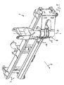
- FIG. 1 illustrated and generally designated 1 mowing and / or Schncidterrorism comprises a here self-propelled vehicle 2, which is not mandatory, at least one here multi-part boom 3 with at least one working head 4, for example, as mowing, cutting or milling head or as clearing or cleaning head may be formed. It can be provided with cutting and / or impact means. In addition to grass mowing heads with one or more vertically or horizontally rotating cutting or impact rollers, for example, a pure hedge trimmer or the like can be mounted. In addition to the front assembly of the boom 3 shown here is also an assembly on the bed or a rear mounting a boom into consideration.
- the boom 3 is mounted on a support 5, which comprises a transverse guide device 6 with, for example, two horizontal profiles and a transversely to the vehicle 2 slidably and towering support 8 with an upstanding and hereinafter referred to as vertical pivot axis 7 around which the boom 3 is pivotable. Since this holder 8 does not laterally reach over the transverse guide device 6, it is not referred to here as the first section of the cantilever.
- the boom Since the boom is held movable on the front side support means 5 transversely to the vehicle 2, it is for a longitudinal transport position described in more detail below according to the Figures 3 and 4 laterally staggered relative to a vertical vehicle longitudinal plane, so that it does not necessarily have to be in a vertical vehicle longitudinal center plane, but may be moved transversely, for example, in front of the passenger side.
- the vehicle 2 may be designed as a narrow-track tractor in order to enable flexible use even in narrow areas. Even larger, truck-like vehicles are possible.
- the can be stored to the rear boom 3 includes in the illustrated embodiment, at least a first, in a working position ( Fig. 1 ) highly aufrable section 9, an adjoining transversely engageable second section 10 and a third, downward in the direction of the working head 4 extendable section 11. All sections 9, 10, 11 are articulated and individually connected to each other by means of drives pivotally connected to each other. On the third section 11, the working head 4 is attached pivotably about an axis 26 directly or with the interposition of further sections.
- the aufragbare from the carrier 5 first portion 9 of the boom 3 is formed here as well as the second portion 10 as a rigid profile, but could also be variable in length.
- the first section may have a length L1 of at least about 1.80 meters to avoid even high obstacles to reach from 2.50 to 3.0 meters in height. In the illustrated embodiment, the length L1 of the first section 9 is about two meters.
- the second section 10 of the boom 3, however, can be significantly shorter, at least in this working position. He has in particular a - possibly variable - length L2 between 0.70 and 1.60 meters.
- this section 10 forms the upper frame part of a portal formed by the boom and übergrcift the obstacle 20 substantially horizontally or only slightly inclined lying. This results in an optimized clear width below the portal, which may include almost the entire length L2 of the section 10.
- the third section 11 is variable in length here in the manner of a telescope, its length L3 can be considerably more than two meters.
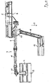
- transverse transport position is the arm 3 transversely before (or behind) the vehicle 2 halterbar that the first portion 9 as the uppermost part of the boom 3 is approximately at the lower edge of a windshield transverse to the vehicle 2, the second section 10 at least almost vertically downwards , which is possible due to its small length, and the third section 11 extends in the cin installed position obliquely upward with a first portion opposite to the transverse component,
- the pack size is therefore minimized, the width low.
- the mowing head 4 can thus be kept horizontal and far down, the driver thus remains an optimized field of view. A vertical mounting of the mowing head 4 is possible and is further down in the FIGS. 11 to 13 shown.
- the transverse transport position is also at least one in the Figures 3 and 4 illustrated longitudinal transport position without any modification allows, in which the boom 3 is frontally mounted longitudinally to the vehicle halterbar, wherein the first section 9 is positioned so far that its articulation to the second section 10 projects beyond the cab 21, the second section approximately horizontally above the Cab 21 is located and the third section 11 extends slightly downward towards a loading area 22, where a - in the illustration after Fig. 4 increased - tray 23 may be provided for the working head 4. Due to the fact that the first section 9 can rise steeply and an intermediate section 10 is provided for bridging to the working section supporting the last section 11, the windshield can be steep without a risk of collision with the boom 3. Nevertheless, the bracket 8 for the boom does not have to be placed far in front of the windshield to allow this collision freedom. The vehicle length can therefore remain low.
- a length and / or angle adjustment of the third section 11 to the geometry of the respective loading surface 22 is adaptable, so that the height of the tray 23 and its longitudinal orientation may be different.
- the third section 11 of the boom is partially extended, so that the working head is located here in the rear area of the loading area 22, in Fig. 4 is for a further up and up located position of the working head 4 of the third section 1 retracted.
- a boom 3 which is optionally at least in a first transport position across the front of the vehicle and in a second transport position along the rear behind a cab 21 of the vehicle 2 can be retrofitted.
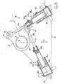
- movable hydraulic drive unit 12 For the pivoting of the boom 3 about the axis 7 a with the boom 3 transverse to the vehicle 2 movable hydraulic drive unit 12 is provided, which here comprises two hydraulic cylinder units 13, 14 which are referred to in the following despite their complicated structure (see below) as a whole hydraulic cylinder , They are horizontal and thus located perpendicular to the pivot axis 7 of the boom.
- the hydraulic cylinders 13, 14 In the rearward pointing zero position of the boom 3 ( Fig. 3 . Fig. 4 . Fig. 8 ), the hydraulic cylinders 13, 14 symmetrical to each other and arranged symmetrically to a pivot axis 7 intersecting vehicle longitudinal plane 24.
- the hydraulic cylinders 13, 14 engage from different directions on levers 15, 16 which are associated with the holder 8.
- the levers 15, 16 are part of a common single or double plate 17.
- the hydraulic cylinders 13, 14 each have a parallel to the pivot axis 7 Anlenkungsachse 27, 28 with their piston rods 13c, 14c.
- Ends are the cylinders 13, 14 via support axes 29, 30, which are also parallel to the axis 7, pivotally supported on a support 31.
- the connecting lines of the mounting axes. 29, 30 with the boom axis 7 form an isosceles Triangle off ( Fig. 8 ).
- the possibility of movement of the boom 3 about the axis 7 to the right and left is completely symmetrical, so as to allow without modification both editing the right and the left roadside.
- the rearwardly facing position of the boom 3 forms a dynamic or static zero position. From this out the boom is pivotable on both sides by at least 90 ° about the axis 7. Then he is in panning to the right side of the vehicle, for example, in the transversely extending position Fig. 1 or the transverse transport position Fig. 2 ,
- the boom 3 can still be pivoted forward by at least 20 ° further, compared to the zero position so by at least 110 °, whereby he then in the in Fig. 6 indicated and slightly before the front end of the vehicle cross position comes.
- each hydraulic cylinder 13, 14 consists of two nested cylinders; nevertheless, only three external connections must be provided:
- the holding on the support axes 29, 30 pivotally supported on the carrier 31 outer piston housing 13a and 14a is provided on the piston crown side with a pressure medium connection AR2 and AL2.
- a pressure medium connection AR2 and AL2 For piston rod side pressure medium loading of the outer cylinder of the terminal BR2 or BL2 is used.
- the piston rod 13b or 14b which can be moved in the piston housing 13a, 14a of the outer cylinder at the same time forms the piston housing for an inner piston rod 13e or 14c, which can then engage the articulation axes 27, 28 of the levers 15, 16 of the plate 17.
- the passage channel AR1 or AL1 which connects the piston head of the inner cylinder with that of the outer cylinder.
- This connection is not mandatory, but simplistic. A further external connection could alternatively be provided.
- Fig. 8 In the zero position after Fig. 8 are the piston rod side ports BR1 and BR2 of the left in the direction of travel cylinder 13 and the piston rod side ports BL1 and BL2 of the right in the direction of travel F cylinder 14 pressurized so that both the piston rods 13c, 14c of the inner cylinder and the piston rods 13b, 14b of the outer Cylinders are retracted.
- the piston bottom ports AR2, AL2 are connected to the return.
- FIGS. 9 to 13 when compared to the FIGS. 1 to 8 unchanged boom 3 in addition a second, also transversely displaceable boom 18 with one or several other working heads 19, such as mowing heads, can be mounted.
- the first cantilever 3 can remain uninfluenced by this in both transport positions, that is to say both transversely in front of the vehicle and also longitudinally to the rear, can be deposited.
- the first boom stands with its holder 8 with respect to the direction of travel F on the far left.
- the second boom 18 is displaced approximately centrally on the transverse guide device 6 and of the mowing head 4 placed vertically about the axis 26 and otherwise exactly as in FIG Fig. 2 filed first boom overlapped.
- the second arm 18 comprises a transverse from the transverse guide device 6 forward in the direction of travel F extending low base 25 through which the third portion 11 of the boom 3 can engage ( Fig. 13 ), so that both arms 3, 18 can be nested.
- this base 25 can also form an at least partially supporting support for a part 11 of the boom 3 which can be deposited backwards.
- An attachment or disassembly of the second arm 18 is easily possible, so that there is a high flexibility.
- the first boom 3 are in the transverse transport position and for a faster ride or for any other work uninfluenced by the second boom 18 in longitudinal transport position pointing backwards.
- Both working heads 4, 19, these can work laterally offset from each other, for example, two strips in front of and behind a guardrail or the like mow.
- the base 25 and the bracket 18 can both largely as far as the direction of travel to the right ( Fig. 9 . Fig. 10 ) as well as, for example, for a link operation to the other side.
Landscapes
- Life Sciences & Earth Sciences (AREA)
- Environmental Sciences (AREA)
- Harvester Elements (AREA)
- Shovels (AREA)
- Working Measures On Existing Buildindgs (AREA)
Claims (16)
- Appareil (1) de fauchage et/ou de coupe, comprenant au moins un bras (3; 18) maintenu de façon mobile sur un véhicule (2), qui peut être étendu vers l'extérieur dans une position de travail, et porte au moins une tête de travail (4; 19),
caractérisé en ce que
un bras (3) peut être déposé, au choix, dans au moins une première position de transport, transversalement devant le véhicule (2), ou dans une deuxième position de transport, longitudinalement vers l'arrière, en s'engageant derrière une cabine (21) du véhicule (2). - Appareil de fauchage et/ou de coupe selon la revendication 1,
caractérisé en ce que
le bras (3) pouvant être déposé vers l'arrière est maintenu sur un dispositif de support frontal (5) de façon transversalement mobile par rapport au véhicule (2), et peut y être maintenu de façon latéralement décalée par rapport à un plan longitudinal médian de véhicule vertical, en vue d'adopter une position orientée vers l'arrière. - Appareil de fauchage et/ou de coupe selon l'une des revendications 1 ou 2,
caractérisé en ce que
le bras (3), qui peut être déposé vers l'arrière, peut être retourné vers l'avant, depuis la position d'engagement vers l'arrière, parallèlement au sens longitudinal du véhicule, en pouvant être déplacé de la même manière vers les deux côtés. - Appareil de fauchage et/ou de coupe selon l'une des revendications 1 à 3,
caractérisé en ce que
pour effectuer les deux mouvements de pivotement du bras (3) dans un plan au moins à peu près perpendiculaire à l'axe de pivotement vertical (7) du bras (3), une unité d'entraînement (12) est prévue, au moyen de laquelle des forces peuvent être appliquées au bras (3) dans deux ou plusieurs directions (29-27 ; 30-28) différentes. - Appareil de fauchage et/ou de coupe selon la revendication 4,
caractérisé en ce que
l'unité d'entraînement (12) est une unité d'entraînement hydraulique ayant au moins deux vérins hydrauliques (13 ; 14) agissant sur le bras (3). - Appareil de fauchage et/ou de coupe selon l'une des revendications 1 à 5,
caractérisé en ce que
l'angle de mouvement du bras (3), depuis la position neutre, est d'au moins 110° des deux côtés. - Appareil de fauchage et/ou de coupe selon l'une des revendications 1 à 6,
caractérisé en ce que
dans une position zéro au moins, les directions d'application de forces (29 à 27 ; 30 à 28) sont disposés de façon symétrique par rapport à un plan longitudinal (24) du véhicule, qui coupe l'axe de pivotement vertical (7) du bras (3). - Appareil de fauchage et/ou de coupe selon l'une des revendications 1 à 7,
caractérisé en ce que
le mouvement de pivotement autour de l'axe vertical (7) peut être effectué de façon libre de toute butée extérieure. - Appareil de fauchage et/ou de coupe selon l'une des revendications 1 à 8,
caractérisé en ce que
dans la position d'orientation longitudinale dirigée vers l'arrière du bras (3), la ligne d'action suivant l'axe longitudinal de l'un au moins des vérins hydrauliques (13 ; 14) passe à côté de l'axe (7) du bras, du côté du véhicule. - Appareil de fauchage et/ou de coupe selon l'une des revendications 1 à 9,
caractérisé en ce que
pour effectuer le mouvement de pivotement du bras (3), au moins un vérin hydraulique (13 ; 14) est prévu, qui comprend un cylindre extérieur (13a, 13b ; 14a, 14b), dont la tige de piston (13b ; 14b) forme un cylindre intérieur (13b, 13c ; 14b, 14c) comprenant une tige de piston intérieure coulissante (13c ; 14c), à la manière d'un télescope. - Appareil de fauchage et/ou de coupe selon l'une des revendications 1 à 10,
caractérisé en ce que
le bras (3) pouvant être déposé vers l'arrière comprend au moins une première section (9) mobile en montée et descente, se dressant vers le haut dans une position de travail, une deuxième section (10) rejoignant la première, pouvant être déployée transversalement, et au moins une troisième section (11) pouvant être déployée vers le bas, en direction de la tête de travail (4). - Appareil de fauchage et/ou de coupe selon la revendication 11,
caractérisé en ce que
dans une position de transport transversale, ce bras (3) peut être maintenu transversalement devant ou derrière le véhicule (2) d'une manière telle que la première section (9) s'étende transversalement au véhicule (2), la deuxième section (10) s'étende au moins presque verticalement vers le bas, et la troisième section (11) s'étende obliquement vers le haut, ou de façon presque horizontale, avec une composante transversale opposée à la première section (9). - Appareil de fauchage et/ou de coupe selon l'une des revendications 11 ou 12
caractérisé en ce que
dans une position de transport longitudinale de ce bras (3), lorsque celui-ci est monté à l'avant, la première section (9) est dressée vers le haut à un point tel que son articulation avec la deuxième section (10) surmonte la cabine (21), que la deuxième section (10) soit située au-dessus de la cabine (21), et que la troisième section (11) s'étende vers le bas en direction d'une surface de chargement (22). - Appareil de fauchage et/ou de coupe selon la revendication 13,
caractérisé en ce que
dans la position de transport longitudinale, une position longitudinale et/ou une position angulaire de la troisième section (11) peut être adaptée à la géométrie de la surface de chargement correspondante (22). - Appareil de fauchage et/ou de coupe selon l'une des revendications 11 à 14,
caractérisé en ce que
un deuxième bras (18) muni d'au moins une autre tête de travail (19) est maintenu sur le véhicule (2). - Appareil de fauchage et/ou de coupe selon l'une des revendications 11 à 14,
caractérisé en ce que
dans sa position de transport, le deuxième bras (18) peut être recouvert, par secteurs (25) au moins, par le premier bras (3), dans la position de transport à rangement transversal de celui-ci.
Priority Applications (1)
| Application Number | Priority Date | Filing Date | Title |
|---|---|---|---|
| PL06007680T PL1759572T3 (pl) | 2005-04-22 | 2006-04-12 | Przyrząd do koszenia i/lub cięcia |
Applications Claiming Priority (5)
| Application Number | Priority Date | Filing Date | Title |
|---|---|---|---|
| DE102005018987.3A DE102005018987B4 (de) | 2005-04-22 | 2005-04-22 | Mäh- und/oder Schneidgerät |
| DE200520006540 DE202005006540U1 (de) | 2005-04-22 | 2005-04-22 | Mäh- und/oder Schneidgerät |
| DE200520006539 DE202005006539U1 (de) | 2005-04-22 | 2005-04-22 | Mäh- und/oder Schneidgerät |
| DE200520006541 DE202005006541U1 (de) | 2005-04-22 | 2005-04-22 | Mäh- und/oder Schneidgerät |
| DE200520006542 DE202005006542U1 (de) | 2005-04-22 | 2005-04-22 | Mäh- und/oder Schneidgerät |
Publications (2)
| Publication Number | Publication Date |
|---|---|
| EP1759572A1 EP1759572A1 (fr) | 2007-03-07 |
| EP1759572B1 true EP1759572B1 (fr) | 2009-02-11 |
Family
ID=36642786
Family Applications (6)
| Application Number | Title | Priority Date | Filing Date |
|---|---|---|---|
| EP06007679A Active EP1762132B1 (fr) | 2005-04-22 | 2006-04-12 | Appareil à faucher et/ou couper |
| EP06007680A Active EP1759572B1 (fr) | 2005-04-22 | 2006-04-12 | Appareil à faucher et/ou couper |
| EP06007677A Active EP1759571B1 (fr) | 2005-04-22 | 2006-04-12 | Appareil à faucher et/ou couper |
| EP06007678A Active EP1762131B1 (fr) | 2005-04-22 | 2006-04-12 | Appareil à faucher et/ou couper |
| EP06007689A Active EP1759573B1 (fr) | 2005-04-22 | 2006-04-12 | Appareil à faucher et/ou couper |
| EP10003552A Active EP2213156B1 (fr) | 2005-04-22 | 2006-04-12 | Appareil à faucher et/ou couper |
Family Applications Before (1)
| Application Number | Title | Priority Date | Filing Date |
|---|---|---|---|
| EP06007679A Active EP1762132B1 (fr) | 2005-04-22 | 2006-04-12 | Appareil à faucher et/ou couper |
Family Applications After (4)
| Application Number | Title | Priority Date | Filing Date |
|---|---|---|---|
| EP06007677A Active EP1759571B1 (fr) | 2005-04-22 | 2006-04-12 | Appareil à faucher et/ou couper |
| EP06007678A Active EP1762131B1 (fr) | 2005-04-22 | 2006-04-12 | Appareil à faucher et/ou couper |
| EP06007689A Active EP1759573B1 (fr) | 2005-04-22 | 2006-04-12 | Appareil à faucher et/ou couper |
| EP10003552A Active EP2213156B1 (fr) | 2005-04-22 | 2006-04-12 | Appareil à faucher et/ou couper |
Country Status (5)
| Country | Link |
|---|---|
| EP (6) | EP1762132B1 (fr) |
| AT (5) | ATE422286T1 (fr) |
| DE (5) | DE502006002793D1 (fr) |
| DK (6) | DK2213156T3 (fr) |
| PL (5) | PL1759572T3 (fr) |
Cited By (1)
| Publication number | Priority date | Publication date | Assignee | Title |
|---|---|---|---|---|
| EP4230797A1 (fr) * | 2022-02-18 | 2023-08-23 | Jürgen Stehr | Accessoire pour le brochage et l'épandage de surfaces et appareil de brochage doté d'un tel accessoire |
Families Citing this family (5)
| Publication number | Priority date | Publication date | Assignee | Title |
|---|---|---|---|---|
| SE534290C2 (sv) * | 2009-09-15 | 2011-06-28 | Bertil Karlsson | Vertikal redskapsbärare avsedd för motorfordon vid väg- och gatuvägunderhåll |
| FR2966693A1 (fr) * | 2010-10-29 | 2012-05-04 | Calvet | Potence porte-outils pour vehicules notamment agricole. |
| DE202014106218U1 (de) | 2014-12-22 | 2016-03-23 | Herder B.V. | Straßenfahrzeug, das mit einem Mähersystem ausgerüstet ist |
| DE102016122229B4 (de) | 2016-11-18 | 2023-06-01 | MULAG FAHRZEUGWERK Heinz Wössner GmbH & Co. KG | Auslegerarm sowie mit einem solchen Auslegerarm ausgestattetes Ausleger-Arbeitsgerät |
| NL2026977B1 (en) | 2020-11-25 | 2022-07-04 | Herder Bv | Boom system, vehicle and method for cutting vegetation |
Family Cites Families (14)
| Publication number | Priority date | Publication date | Assignee | Title |
|---|---|---|---|---|
| US3087296A (en) * | 1962-05-15 | 1963-04-30 | John T Cowles | Brush cutter |
| DE3218525C2 (de) * | 1982-05-17 | 1986-01-16 | Gerhard Dücker KG Landmaschinenfabrik, 4424 Stadtlohn | Böschungsmähgerät |
| EP0150975A3 (fr) * | 1984-01-28 | 1987-10-21 | Turner International (Engineering) Limited | Faucheuses |
| DE3709681A1 (de) * | 1986-12-18 | 1988-10-06 | Strautmann & Soehne | Schneidwerk fuer flachsilo-entnahmegeraet |
| NL192992C (nl) * | 1994-11-03 | 1998-07-03 | Conver Machines B V | Inrichting voor het dragen van een gereedschap. |
| IT1282257B1 (it) * | 1995-06-12 | 1998-03-16 | Gonzaga Odoardo Guerrieri | Insieme di braccio portattrezzi multifunzionale e componibile con altri elementi atto ad eseguire operazioni lateralmente ad un mezzo |
| ES2212505T3 (es) * | 1998-04-24 | 2004-07-16 | Binger France Sarl | Dispositivo de soporte de maquina utilizable particularmente en agricultura, arboricultura y viticultura. |
| US6047531A (en) * | 1999-01-08 | 2000-04-11 | Bryan, Iii; William | Apparatus for cutting brush |
| DE10027133B4 (de) * | 2000-05-31 | 2005-03-03 | Mulag Fahrzeugwerk Heinz Wössner GmbH u. Co KG | Mähgerät mit zwei Mähköpfen |
| ITBO20010595A1 (it) * | 2001-09-27 | 2003-03-27 | Ferri Srl | Dispositivo a braccio idraulico articolato particolarmente per un utensile agricolo |
| ATE300168T1 (de) * | 2002-05-15 | 2005-08-15 | Laserjet S R L | Buschmäherfahrzeug |
| DE10227261B4 (de) * | 2002-06-19 | 2016-02-18 | Gerhard Dücker GmbH & Co. KG Landmaschinenfabrik | Mäh- und/oder Schneidgerät |
| DE20211861U1 (de) * | 2002-08-01 | 2002-11-14 | Duecker Gerhard Gmbh & Co Kg | Mähgerät |
| DE102004032573A1 (de) | 2004-07-05 | 2006-02-23 | GÖDDE Maschinenbau GmbH | Trägerfahrzeug mit Mähgerät |
-
2006
- 2006-04-12 DK DK10003552.6T patent/DK2213156T3/da active
- 2006-04-12 DK DK06007689T patent/DK1759573T3/da active
- 2006-04-12 EP EP06007679A patent/EP1762132B1/fr active Active
- 2006-04-12 PL PL06007680T patent/PL1759572T3/pl unknown
- 2006-04-12 EP EP06007680A patent/EP1759572B1/fr active Active
- 2006-04-12 PL PL10003552T patent/PL2213156T3/pl unknown
- 2006-04-12 DK DK06007677.5T patent/DK1759571T3/da active
- 2006-04-12 AT AT06007680T patent/ATE422286T1/de active
- 2006-04-12 DK DK06007680T patent/DK1759572T3/da active
- 2006-04-12 AT AT06007677T patent/ATE482612T1/de active
- 2006-04-12 PL PL06007689T patent/PL1759573T3/pl unknown
- 2006-04-12 EP EP06007677A patent/EP1759571B1/fr active Active
- 2006-04-12 DE DE502006002793T patent/DE502006002793D1/de active Active
- 2006-04-12 DE DE502006007952T patent/DE502006007952D1/de active Active
- 2006-04-12 AT AT06007678T patent/ATE405143T1/de not_active IP Right Cessation
- 2006-04-12 EP EP06007678A patent/EP1762131B1/fr active Active
- 2006-04-12 DK DK06007679T patent/DK1762132T3/da active
- 2006-04-12 DE DE502006000872T patent/DE502006000872D1/de active Active
- 2006-04-12 DE DE502006002048T patent/DE502006002048D1/de active Active
- 2006-04-12 PL PL06007679T patent/PL1762132T3/pl unknown
- 2006-04-12 DK DK06007678T patent/DK1762131T3/da active
- 2006-04-12 AT AT06007679T patent/ATE413801T1/de active
- 2006-04-12 EP EP06007689A patent/EP1759573B1/fr active Active
- 2006-04-12 AT AT06007689T patent/ATE397376T1/de active
- 2006-04-12 DE DE502006001368T patent/DE502006001368D1/de active Active
- 2006-04-12 PL PL06007678T patent/PL1762131T3/pl unknown
- 2006-04-12 EP EP10003552A patent/EP2213156B1/fr active Active
Cited By (1)
| Publication number | Priority date | Publication date | Assignee | Title |
|---|---|---|---|---|
| EP4230797A1 (fr) * | 2022-02-18 | 2023-08-23 | Jürgen Stehr | Accessoire pour le brochage et l'épandage de surfaces et appareil de brochage doté d'un tel accessoire |
Also Published As
| Publication number | Publication date |
|---|---|
| EP2213156B1 (fr) | 2013-04-03 |
| EP1762132A1 (fr) | 2007-03-14 |
| EP1762132B1 (fr) | 2008-11-12 |
| EP1762131B1 (fr) | 2008-08-20 |
| EP1759573A1 (fr) | 2007-03-07 |
| PL1762131T3 (pl) | 2009-02-27 |
| PL1762132T3 (pl) | 2009-06-30 |
| PL1759573T3 (pl) | 2009-04-30 |
| DK1762131T3 (da) | 2008-12-08 |
| DK1762132T3 (da) | 2009-02-23 |
| ATE422286T1 (de) | 2009-02-15 |
| EP1759571B1 (fr) | 2010-09-29 |
| EP1759573B1 (fr) | 2008-06-04 |
| DE502006001368D1 (de) | 2008-10-02 |
| PL2213156T3 (pl) | 2013-11-29 |
| DK1759571T3 (da) | 2011-01-24 |
| ATE397376T1 (de) | 2008-06-15 |
| DE502006002048D1 (de) | 2008-12-24 |
| EP2213156A2 (fr) | 2010-08-04 |
| EP1759572A1 (fr) | 2007-03-07 |
| DK2213156T3 (da) | 2013-07-08 |
| DK1759573T3 (da) | 2008-10-13 |
| EP1762131A1 (fr) | 2007-03-14 |
| EP1759571A1 (fr) | 2007-03-07 |
| DE502006007952D1 (de) | 2010-11-11 |
| DE502006000872D1 (de) | 2008-07-17 |
| ATE482612T1 (de) | 2010-10-15 |
| EP2213156A3 (fr) | 2011-10-05 |
| DE502006002793D1 (de) | 2009-03-26 |
| ATE413801T1 (de) | 2008-11-15 |
| ATE405143T1 (de) | 2008-09-15 |
| PL1759572T3 (pl) | 2009-09-30 |
| DK1759572T3 (da) | 2009-05-25 |
Similar Documents
| Publication | Publication Date | Title |
|---|---|---|
| EP1759572B1 (fr) | Appareil à faucher et/ou couper | |
| DE102011105556B4 (de) | Straßenbaumaschine | |
| DE10039097A1 (de) | Verfahren und Vorrichtung zum Schwenken der Abteiler von mehrteiligen landwirtschaftlichen Erntemaschinen | |
| EP0073360B1 (fr) | Faucheuse | |
| EP1813730A2 (fr) | Chargeur frontal et cabine pour tracteur | |
| DE202004011990U1 (de) | Umschlaggerät | |
| DE19534695C2 (de) | An einem Schlepper ansetzbares Heckmähwerk | |
| DE102016102894A1 (de) | Frontgeräteträger mit einem ausfahrbaren Ausleger für Anbaugeräte und Verfahren zur Steuerung eines Frontgeräteträgers | |
| DE10321683B4 (de) | Pfosten-Freimäher und Verfahren zum Einsatz des Freimähers | |
| DE102005018987B4 (de) | Mäh- und/oder Schneidgerät | |
| DE202005006541U1 (de) | Mäh- und/oder Schneidgerät | |
| EP1142467A1 (fr) | Dispositif de cueillette de céréales | |
| EP3266292B1 (fr) | Outil agricole tracté et agricole et attelage comprenant un tel outil tracté | |
| EP3323283A1 (fr) | Bras ainsi qu'un appareil de travail à bras muni d'un tel bras | |
| EP3005853B1 (fr) | Outil agricole et procédé de fonctionnement d'un outil agricole | |
| EP1612335A2 (fr) | Dispositif de balayage automobile | |
| EP0545351B1 (fr) | Appareil porteur pour un outil de travail | |
| DE102021102774A1 (de) | Mähwerksanordnung | |
| DE4443170C2 (de) | Lademaschine mit verstellbarer Kabine | |
| EP0846411A1 (fr) | Véhicule agricole pour distribuer de l'ensilage aux animaux | |
| DE3630873A1 (de) | Geraeteanbauvorrichtung fuer landwirtschaftlich nutzbare zugfahrzeuge | |
| AT523600B1 (de) | Mähwerksanordnung | |
| EP1763987A1 (fr) | Dispositif pour faucher et/ou couper | |
| EP2526758A1 (fr) | Faucheuse | |
| EP1782674B1 (fr) | Faucheuse |
Legal Events
| Date | Code | Title | Description |
|---|---|---|---|
| PUAI | Public reference made under article 153(3) epc to a published international application that has entered the european phase |
Free format text: ORIGINAL CODE: 0009012 |
|
| AK | Designated contracting states |
Kind code of ref document: A1 Designated state(s): AT BE BG CH CY CZ DE DK EE ES FI FR GB GR HU IE IS IT LI LT LU LV MC NL PL PT RO SE SI SK TR |
|
| AX | Request for extension of the european patent |
Extension state: AL BA HR MK YU |
|
| 17P | Request for examination filed |
Effective date: 20070329 |
|
| AKX | Designation fees paid |
Designated state(s): AT BE BG CH CY CZ DE DK EE ES FI FR GB GR HU IE IS IT LI LT LU LV MC NL PL PT RO SE SI SK TR |
|
| GRAP | Despatch of communication of intention to grant a patent |
Free format text: ORIGINAL CODE: EPIDOSNIGR1 |
|
| GRAS | Grant fee paid |
Free format text: ORIGINAL CODE: EPIDOSNIGR3 |
|
| GRAA | (expected) grant |
Free format text: ORIGINAL CODE: 0009210 |
|
| AK | Designated contracting states |
Kind code of ref document: B1 Designated state(s): AT BE BG CH CY CZ DE DK EE ES FI FR GB GR HU IE IS IT LI LT LU LV MC NL PL PT RO SE SI SK TR |
|
| REG | Reference to a national code |
Ref country code: GB Ref legal event code: FG4D Free format text: NOT ENGLISH |
|
| REG | Reference to a national code |
Ref country code: CH Ref legal event code: EP |
|
| REG | Reference to a national code |
Ref country code: IE Ref legal event code: FG4D Free format text: LANGUAGE OF EP DOCUMENT: GERMAN |
|
| REF | Corresponds to: |
Ref document number: 502006002793 Country of ref document: DE Date of ref document: 20090326 Kind code of ref document: P |
|
| REG | Reference to a national code |
Ref country code: DK Ref legal event code: T3 |
|
| PG25 | Lapsed in a contracting state [announced via postgrant information from national office to epo] |
Ref country code: FI Free format text: LAPSE BECAUSE OF FAILURE TO SUBMIT A TRANSLATION OF THE DESCRIPTION OR TO PAY THE FEE WITHIN THE PRESCRIBED TIME-LIMIT Effective date: 20090211 Ref country code: ES Free format text: LAPSE BECAUSE OF FAILURE TO SUBMIT A TRANSLATION OF THE DESCRIPTION OR TO PAY THE FEE WITHIN THE PRESCRIBED TIME-LIMIT Effective date: 20090522 Ref country code: SI Free format text: LAPSE BECAUSE OF FAILURE TO SUBMIT A TRANSLATION OF THE DESCRIPTION OR TO PAY THE FEE WITHIN THE PRESCRIBED TIME-LIMIT Effective date: 20090211 Ref country code: LT Free format text: LAPSE BECAUSE OF FAILURE TO SUBMIT A TRANSLATION OF THE DESCRIPTION OR TO PAY THE FEE WITHIN THE PRESCRIBED TIME-LIMIT Effective date: 20090211 |
|
| PG25 | Lapsed in a contracting state [announced via postgrant information from national office to epo] |
Ref country code: LV Free format text: LAPSE BECAUSE OF FAILURE TO SUBMIT A TRANSLATION OF THE DESCRIPTION OR TO PAY THE FEE WITHIN THE PRESCRIBED TIME-LIMIT Effective date: 20090211 Ref country code: IS Free format text: LAPSE BECAUSE OF FAILURE TO SUBMIT A TRANSLATION OF THE DESCRIPTION OR TO PAY THE FEE WITHIN THE PRESCRIBED TIME-LIMIT Effective date: 20090611 Ref country code: SE Free format text: LAPSE BECAUSE OF FAILURE TO SUBMIT A TRANSLATION OF THE DESCRIPTION OR TO PAY THE FEE WITHIN THE PRESCRIBED TIME-LIMIT Effective date: 20090511 |
|
| REG | Reference to a national code |
Ref country code: IE Ref legal event code: FD4D |
|
| REG | Reference to a national code |
Ref country code: PL Ref legal event code: T3 |
|
| PG25 | Lapsed in a contracting state [announced via postgrant information from national office to epo] |
Ref country code: EE Free format text: LAPSE BECAUSE OF FAILURE TO SUBMIT A TRANSLATION OF THE DESCRIPTION OR TO PAY THE FEE WITHIN THE PRESCRIBED TIME-LIMIT Effective date: 20090211 Ref country code: CZ Free format text: LAPSE BECAUSE OF FAILURE TO SUBMIT A TRANSLATION OF THE DESCRIPTION OR TO PAY THE FEE WITHIN THE PRESCRIBED TIME-LIMIT Effective date: 20090211 Ref country code: IE Free format text: LAPSE BECAUSE OF FAILURE TO SUBMIT A TRANSLATION OF THE DESCRIPTION OR TO PAY THE FEE WITHIN THE PRESCRIBED TIME-LIMIT Effective date: 20090211 Ref country code: PT Free format text: LAPSE BECAUSE OF FAILURE TO SUBMIT A TRANSLATION OF THE DESCRIPTION OR TO PAY THE FEE WITHIN THE PRESCRIBED TIME-LIMIT Effective date: 20090713 |
|
| PLBI | Opposition filed |
Free format text: ORIGINAL CODE: 0009260 |
|
| PG25 | Lapsed in a contracting state [announced via postgrant information from national office to epo] |
Ref country code: RO Free format text: LAPSE BECAUSE OF FAILURE TO SUBMIT A TRANSLATION OF THE DESCRIPTION OR TO PAY THE FEE WITHIN THE PRESCRIBED TIME-LIMIT Effective date: 20090211 Ref country code: SK Free format text: LAPSE BECAUSE OF FAILURE TO SUBMIT A TRANSLATION OF THE DESCRIPTION OR TO PAY THE FEE WITHIN THE PRESCRIBED TIME-LIMIT Effective date: 20090211 |
|
| PLAX | Notice of opposition and request to file observation + time limit sent |
Free format text: ORIGINAL CODE: EPIDOSNOBS2 |
|
| 26 | Opposition filed |
Opponent name: MULAG FAHRZEUGWERK HEINZ WOESSNER GMBH & CO. KG Effective date: 20091111 |
|
| REG | Reference to a national code |
Ref country code: FR Ref legal event code: ST Effective date: 20091231 |
|
| PG25 | Lapsed in a contracting state [announced via postgrant information from national office to epo] |
Ref country code: BG Free format text: LAPSE BECAUSE OF FAILURE TO SUBMIT A TRANSLATION OF THE DESCRIPTION OR TO PAY THE FEE WITHIN THE PRESCRIBED TIME-LIMIT Effective date: 20090511 |
|
| NLR1 | Nl: opposition has been filed with the epo |
Opponent name: MULAG FAHRZEUGWERK HEINZ WOESSNER GMBH & CO. KG |
|
| PG25 | Lapsed in a contracting state [announced via postgrant information from national office to epo] |
Ref country code: FR Free format text: LAPSE BECAUSE OF NON-PAYMENT OF DUE FEES Effective date: 20091222 Ref country code: MC Free format text: LAPSE BECAUSE OF NON-PAYMENT OF DUE FEES Effective date: 20090430 |
|
| PLAF | Information modified related to communication of a notice of opposition and request to file observations + time limit |
Free format text: ORIGINAL CODE: EPIDOSCOBS2 |
|
| PLBB | Reply of patent proprietor to notice(s) of opposition received |
Free format text: ORIGINAL CODE: EPIDOSNOBS3 |
|
| PG25 | Lapsed in a contracting state [announced via postgrant information from national office to epo] |
Ref country code: GR Free format text: LAPSE BECAUSE OF FAILURE TO SUBMIT A TRANSLATION OF THE DESCRIPTION OR TO PAY THE FEE WITHIN THE PRESCRIBED TIME-LIMIT Effective date: 20090512 |
|
| REG | Reference to a national code |
Ref country code: CH Ref legal event code: PL |
|
| GBPC | Gb: european patent ceased through non-payment of renewal fee |
Effective date: 20100412 |
|
| PG25 | Lapsed in a contracting state [announced via postgrant information from national office to epo] |
Ref country code: CH Free format text: LAPSE BECAUSE OF NON-PAYMENT OF DUE FEES Effective date: 20100430 Ref country code: LI Free format text: LAPSE BECAUSE OF NON-PAYMENT OF DUE FEES Effective date: 20100430 |
|
| PG25 | Lapsed in a contracting state [announced via postgrant information from national office to epo] |
Ref country code: IT Free format text: LAPSE BECAUSE OF FAILURE TO SUBMIT A TRANSLATION OF THE DESCRIPTION OR TO PAY THE FEE WITHIN THE PRESCRIBED TIME-LIMIT Effective date: 20090211 Ref country code: GB Free format text: LAPSE BECAUSE OF NON-PAYMENT OF DUE FEES Effective date: 20100412 |
|
| PLBD | Termination of opposition procedure: decision despatched |
Free format text: ORIGINAL CODE: EPIDOSNOPC1 |
|
| PLBP | Opposition withdrawn |
Free format text: ORIGINAL CODE: 0009264 |
|
| PG25 | Lapsed in a contracting state [announced via postgrant information from national office to epo] |
Ref country code: LU Free format text: LAPSE BECAUSE OF NON-PAYMENT OF DUE FEES Effective date: 20090412 |
|
| PG25 | Lapsed in a contracting state [announced via postgrant information from national office to epo] |
Ref country code: HU Free format text: LAPSE BECAUSE OF FAILURE TO SUBMIT A TRANSLATION OF THE DESCRIPTION OR TO PAY THE FEE WITHIN THE PRESCRIBED TIME-LIMIT Effective date: 20090812 |
|
| PLBM | Termination of opposition procedure: date of legal effect published |
Free format text: ORIGINAL CODE: 0009276 |
|
| STAA | Information on the status of an ep patent application or granted ep patent |
Free format text: STATUS: OPPOSITION PROCEDURE CLOSED |
|
| 27C | Opposition proceedings terminated |
Effective date: 20110425 |
|
| PG25 | Lapsed in a contracting state [announced via postgrant information from national office to epo] |
Ref country code: TR Free format text: LAPSE BECAUSE OF FAILURE TO SUBMIT A TRANSLATION OF THE DESCRIPTION OR TO PAY THE FEE WITHIN THE PRESCRIBED TIME-LIMIT Effective date: 20090211 |
|
| PG25 | Lapsed in a contracting state [announced via postgrant information from national office to epo] |
Ref country code: CY Free format text: LAPSE BECAUSE OF FAILURE TO SUBMIT A TRANSLATION OF THE DESCRIPTION OR TO PAY THE FEE WITHIN THE PRESCRIBED TIME-LIMIT Effective date: 20090211 |
|
| PGFP | Annual fee paid to national office [announced via postgrant information from national office to epo] |
Ref country code: DK Payment date: 20230428 Year of fee payment: 18 Ref country code: DE Payment date: 20230430 Year of fee payment: 18 |
|
| PGFP | Annual fee paid to national office [announced via postgrant information from national office to epo] |
Ref country code: PL Payment date: 20230425 Year of fee payment: 18 Ref country code: AT Payment date: 20230426 Year of fee payment: 18 |
|
| PGFP | Annual fee paid to national office [announced via postgrant information from national office to epo] |
Ref country code: BE Payment date: 20230428 Year of fee payment: 18 |
|
| PGFP | Annual fee paid to national office [announced via postgrant information from national office to epo] |
Ref country code: NL Payment date: 20240411 Year of fee payment: 19 |