EP1759572B1 - Mowing and/or cutting device - Google Patents
Mowing and/or cutting device Download PDFInfo
- Publication number
- EP1759572B1 EP1759572B1 EP06007680A EP06007680A EP1759572B1 EP 1759572 B1 EP1759572 B1 EP 1759572B1 EP 06007680 A EP06007680 A EP 06007680A EP 06007680 A EP06007680 A EP 06007680A EP 1759572 B1 EP1759572 B1 EP 1759572B1
- Authority
- EP
- European Patent Office
- Prior art keywords
- mowing
- boom arm
- section
- vehicle
- cutting apparatus
- Prior art date
- Legal status (The legal status is an assumption and is not a legal conclusion. Google has not performed a legal analysis and makes no representation as to the accuracy of the status listed.)
- Active
Links
Images


Classifications
-
- A—HUMAN NECESSITIES
- A01—AGRICULTURE; FORESTRY; ANIMAL HUSBANDRY; HUNTING; TRAPPING; FISHING
- A01D—HARVESTING; MOWING
- A01D34/00—Mowers; Mowing apparatus of harvesters
- A01D34/835—Mowers; Mowing apparatus of harvesters specially adapted for particular purposes
- A01D34/86—Mowers; Mowing apparatus of harvesters specially adapted for particular purposes for use on sloping ground, e.g. on embankments or in ditches
- A01D34/866—Mounting means
Definitions
- the invention relates to a mowing and / or cutting device with a halterbaren to a vehicle and with respect to this movable boom for supporting a working head according to the preamble of claim 1 (see, eg EP-A-1 159 866 ).
- the invention is based on the problem of achieving an improvement here.
- At least two different transport positions of a boom are possible, so that it can be decided depending on the application, whether this boom should be held longitudinally or transversely to the vehicle.
- the truck bed for winter service can be provided with a high-build and heavy grit container with applicator and then the boom with the working head in front of the vehicle are held transversely, whereas the boom after removal of the grit container then the cab can be stored across the back ,
- the boom When the boom is movably supported transversely to the vehicle on a front-side support means and laterally displaceable for a rearward position thereof opposite a vertical vehicle longitudinal plane, this can bring about a significant improvement in the driver's field of vision.
- the boom can then be moved far to the right, for example, to allow a left-seated driver a large field of view.
- the boom from the rearward position out in a similar manner to both sides can be pivoted forward. This allows use of the working head on both sides of the vehicle, without in between A plugging, a dismantling or conversion or similar measures would be required.
- At least two hydraulic cylinders which can be acted on the delivery arm are provided, which can be realized with a low control effort and allows favorable angles of attack for the introduction of force.
- the directions of force are arranged axially symmetrical to a vehicle longitudinal plane intersecting the vertical pivot axis of the boom, resulting in the same conditions for both pivoting directions of the boom from this position out.
- the boom can also reach laterally from the vehicle. At an angle of about 110 ° is also a Schrägverschwenken with, for example, forward facing the vehicle component possible. The driver can keep an eye on the working head very well.
- hydraulic cylinders each comprise an outer cylinder, the piston rod like a telescope an inner cylinder with an extendable and at the Anlenkungsachse on the lever Deflection axis attacking inner piston rod forms.
- both the piston rod of the outer and the piston rod of the inner cylinder can be retracted, so that the drive unit can be arranged very compact and space-saving behind the actual vertical pivot axis of the boom.
- the boom starting from a vehicle-side support, comprises at least a first section which can be elevated highly in a working position, an adjoining transversely engageable second section and at least one third section which can be extended downward in the direction of the working head, it is possible to also to overlap wide obstacles, wherein the cross-extending portion is guided in this overarching position above the obstacle.
- the boom thereby forms a portal, whose upper frame part extends substantially transversely and thus can bridge a considerable width.
- the third section is particularly variable in length, in order to be able to extend to the ground even at a high position of the section crossing an obstacle.
- the second, hinged to the first section may have a length of at least 90 centimeters, often well over 1.20 meters, which also allows the spread of wide directional and Orts fundamentaltagen possible.
- a spreading over of a driver's cab of the vehicle is possible with the training according to the invention without any problems, which may be due to the towering first section of this close to a steep windshield and unlike the prior art requires no large distance from this in the vehicle longitudinal direction.
- the boom can still be folded very space-saving in a transverse transport position by then the first section transverse to the vehicle, the second section at least almost vertically downwards and the third section obliquely upward or almost horizontally with a first section opposite transverse component.
- the working head in order to leave room for a second boom with a second working head, the working head can then also be vertical.
- a length and / or angle adjustment of the third section can be adapted to the geometry of the respective loading area, so that it can be of different lengths or heights.
- a great advantage of the invention is also that, despite the different transport positions of a boom and a second boom can be provided with at least one other working head, such as a laterally offset mowing of grass strips in front and behind guide posts. Even with the assembly of the second arm can take the transport of the first boom still both transport positions with the space-saving transverse transport position, where he can save space in his transversely deposited transport position at least partially overlap the second boom.
- the second arm can form a bearing surface for the first.
- FIG. 1 illustrated and generally designated 1 mowing and / or Schncidterrorism comprises a here self-propelled vehicle 2, which is not mandatory, at least one here multi-part boom 3 with at least one working head 4, for example, as mowing, cutting or milling head or as clearing or cleaning head may be formed. It can be provided with cutting and / or impact means. In addition to grass mowing heads with one or more vertically or horizontally rotating cutting or impact rollers, for example, a pure hedge trimmer or the like can be mounted. In addition to the front assembly of the boom 3 shown here is also an assembly on the bed or a rear mounting a boom into consideration.
- the boom 3 is mounted on a support 5, which comprises a transverse guide device 6 with, for example, two horizontal profiles and a transversely to the vehicle 2 slidably and towering support 8 with an upstanding and hereinafter referred to as vertical pivot axis 7 around which the boom 3 is pivotable. Since this holder 8 does not laterally reach over the transverse guide device 6, it is not referred to here as the first section of the cantilever.
- the boom Since the boom is held movable on the front side support means 5 transversely to the vehicle 2, it is for a longitudinal transport position described in more detail below according to the Figures 3 and 4 laterally staggered relative to a vertical vehicle longitudinal plane, so that it does not necessarily have to be in a vertical vehicle longitudinal center plane, but may be moved transversely, for example, in front of the passenger side.
- the vehicle 2 may be designed as a narrow-track tractor in order to enable flexible use even in narrow areas. Even larger, truck-like vehicles are possible.
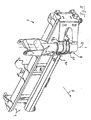
- the can be stored to the rear boom 3 includes in the illustrated embodiment, at least a first, in a working position ( Fig. 1 ) highly aufrable section 9, an adjoining transversely engageable second section 10 and a third, downward in the direction of the working head 4 extendable section 11. All sections 9, 10, 11 are articulated and individually connected to each other by means of drives pivotally connected to each other. On the third section 11, the working head 4 is attached pivotably about an axis 26 directly or with the interposition of further sections.
- the aufragbare from the carrier 5 first portion 9 of the boom 3 is formed here as well as the second portion 10 as a rigid profile, but could also be variable in length.
- the first section may have a length L1 of at least about 1.80 meters to avoid even high obstacles to reach from 2.50 to 3.0 meters in height. In the illustrated embodiment, the length L1 of the first section 9 is about two meters.
- the second section 10 of the boom 3, however, can be significantly shorter, at least in this working position. He has in particular a - possibly variable - length L2 between 0.70 and 1.60 meters.
- this section 10 forms the upper frame part of a portal formed by the boom and übergrcift the obstacle 20 substantially horizontally or only slightly inclined lying. This results in an optimized clear width below the portal, which may include almost the entire length L2 of the section 10.
- the third section 11 is variable in length here in the manner of a telescope, its length L3 can be considerably more than two meters.
- transverse transport position is the arm 3 transversely before (or behind) the vehicle 2 halterbar that the first portion 9 as the uppermost part of the boom 3 is approximately at the lower edge of a windshield transverse to the vehicle 2, the second section 10 at least almost vertically downwards , which is possible due to its small length, and the third section 11 extends in the cin installed position obliquely upward with a first portion opposite to the transverse component,
- the pack size is therefore minimized, the width low.
- the mowing head 4 can thus be kept horizontal and far down, the driver thus remains an optimized field of view. A vertical mounting of the mowing head 4 is possible and is further down in the FIGS. 11 to 13 shown.
- the transverse transport position is also at least one in the Figures 3 and 4 illustrated longitudinal transport position without any modification allows, in which the boom 3 is frontally mounted longitudinally to the vehicle halterbar, wherein the first section 9 is positioned so far that its articulation to the second section 10 projects beyond the cab 21, the second section approximately horizontally above the Cab 21 is located and the third section 11 extends slightly downward towards a loading area 22, where a - in the illustration after Fig. 4 increased - tray 23 may be provided for the working head 4. Due to the fact that the first section 9 can rise steeply and an intermediate section 10 is provided for bridging to the working section supporting the last section 11, the windshield can be steep without a risk of collision with the boom 3. Nevertheless, the bracket 8 for the boom does not have to be placed far in front of the windshield to allow this collision freedom. The vehicle length can therefore remain low.
- a length and / or angle adjustment of the third section 11 to the geometry of the respective loading surface 22 is adaptable, so that the height of the tray 23 and its longitudinal orientation may be different.
- the third section 11 of the boom is partially extended, so that the working head is located here in the rear area of the loading area 22, in Fig. 4 is for a further up and up located position of the working head 4 of the third section 1 retracted.
- a boom 3 which is optionally at least in a first transport position across the front of the vehicle and in a second transport position along the rear behind a cab 21 of the vehicle 2 can be retrofitted.
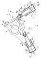
- movable hydraulic drive unit 12 For the pivoting of the boom 3 about the axis 7 a with the boom 3 transverse to the vehicle 2 movable hydraulic drive unit 12 is provided, which here comprises two hydraulic cylinder units 13, 14 which are referred to in the following despite their complicated structure (see below) as a whole hydraulic cylinder , They are horizontal and thus located perpendicular to the pivot axis 7 of the boom.
- the hydraulic cylinders 13, 14 In the rearward pointing zero position of the boom 3 ( Fig. 3 . Fig. 4 . Fig. 8 ), the hydraulic cylinders 13, 14 symmetrical to each other and arranged symmetrically to a pivot axis 7 intersecting vehicle longitudinal plane 24.
- the hydraulic cylinders 13, 14 engage from different directions on levers 15, 16 which are associated with the holder 8.
- the levers 15, 16 are part of a common single or double plate 17.
- the hydraulic cylinders 13, 14 each have a parallel to the pivot axis 7 Anlenkungsachse 27, 28 with their piston rods 13c, 14c.
- Ends are the cylinders 13, 14 via support axes 29, 30, which are also parallel to the axis 7, pivotally supported on a support 31.
- the connecting lines of the mounting axes. 29, 30 with the boom axis 7 form an isosceles Triangle off ( Fig. 8 ).
- the possibility of movement of the boom 3 about the axis 7 to the right and left is completely symmetrical, so as to allow without modification both editing the right and the left roadside.
- the rearwardly facing position of the boom 3 forms a dynamic or static zero position. From this out the boom is pivotable on both sides by at least 90 ° about the axis 7. Then he is in panning to the right side of the vehicle, for example, in the transversely extending position Fig. 1 or the transverse transport position Fig. 2 ,
- the boom 3 can still be pivoted forward by at least 20 ° further, compared to the zero position so by at least 110 °, whereby he then in the in Fig. 6 indicated and slightly before the front end of the vehicle cross position comes.
- each hydraulic cylinder 13, 14 consists of two nested cylinders; nevertheless, only three external connections must be provided:
- the holding on the support axes 29, 30 pivotally supported on the carrier 31 outer piston housing 13a and 14a is provided on the piston crown side with a pressure medium connection AR2 and AL2.
- a pressure medium connection AR2 and AL2 For piston rod side pressure medium loading of the outer cylinder of the terminal BR2 or BL2 is used.
- the piston rod 13b or 14b which can be moved in the piston housing 13a, 14a of the outer cylinder at the same time forms the piston housing for an inner piston rod 13e or 14c, which can then engage the articulation axes 27, 28 of the levers 15, 16 of the plate 17.
- the passage channel AR1 or AL1 which connects the piston head of the inner cylinder with that of the outer cylinder.
- This connection is not mandatory, but simplistic. A further external connection could alternatively be provided.
- Fig. 8 In the zero position after Fig. 8 are the piston rod side ports BR1 and BR2 of the left in the direction of travel cylinder 13 and the piston rod side ports BL1 and BL2 of the right in the direction of travel F cylinder 14 pressurized so that both the piston rods 13c, 14c of the inner cylinder and the piston rods 13b, 14b of the outer Cylinders are retracted.
- the piston bottom ports AR2, AL2 are connected to the return.
- FIGS. 9 to 13 when compared to the FIGS. 1 to 8 unchanged boom 3 in addition a second, also transversely displaceable boom 18 with one or several other working heads 19, such as mowing heads, can be mounted.
- the first cantilever 3 can remain uninfluenced by this in both transport positions, that is to say both transversely in front of the vehicle and also longitudinally to the rear, can be deposited.
- the first boom stands with its holder 8 with respect to the direction of travel F on the far left.
- the second boom 18 is displaced approximately centrally on the transverse guide device 6 and of the mowing head 4 placed vertically about the axis 26 and otherwise exactly as in FIG Fig. 2 filed first boom overlapped.
- the second arm 18 comprises a transverse from the transverse guide device 6 forward in the direction of travel F extending low base 25 through which the third portion 11 of the boom 3 can engage ( Fig. 13 ), so that both arms 3, 18 can be nested.
- this base 25 can also form an at least partially supporting support for a part 11 of the boom 3 which can be deposited backwards.
- An attachment or disassembly of the second arm 18 is easily possible, so that there is a high flexibility.
- the first boom 3 are in the transverse transport position and for a faster ride or for any other work uninfluenced by the second boom 18 in longitudinal transport position pointing backwards.
- Both working heads 4, 19, these can work laterally offset from each other, for example, two strips in front of and behind a guardrail or the like mow.
- the base 25 and the bracket 18 can both largely as far as the direction of travel to the right ( Fig. 9 . Fig. 10 ) as well as, for example, for a link operation to the other side.
Abstract
Description
Die Erfindung betrifft ein Mäh- und/oder Schneidgerät mit einem an einem Fahrzeug halterbaren und gegenüber diesem beweglichen Ausleger zum Tragen eines Arbeitskopfes nach dem Oberbegriff des Anspruchs 1 (siehe z.B.
Es sind derartige Geräte bekannt, bei denen ein Ausleger nach hinten über eine Fahrerkabine greifend ablegbar ist, so daß ein von dem Ausleger gehaltener Arbeitskopf auf einer Halterung der Ladefläche abstützbar ist. Damit ist die Nutzbarkeit der Ladefläche für andere Zwecke räumlich eingeschränkt, bei einer voll belasteten Ladefläche kann sich zudem eine ungünstige Gewichtsverteilung durch den dort auch noch abgelegten Arbeitskopf ergeben.There are such devices are known in which a boom to the rear over a driver's cab is laid down, so that a held by the boom working head can be supported on a bracket of the cargo area. Thus, the usability of the loading area for other purposes is limited in space, in a fully loaded loading area can also result in an unfavorable weight distribution by the there also stored working head.
Der Erfindung liegt das Problem zugrunde, hier eine Verbesserung zu erreichen.The invention is based on the problem of achieving an improvement here.
Die Erfindung löst dieses Problem durch ein Mäh- und/oder Schneidgerät mit den Merkmalen des Anspruchs 1. Hinsichtlich vorteilhafter Ausgestaltungen wird auf die abhängigen Ansprüche 2 bis 16 verwiesen.The invention solves this problem by a cutting and / or cutting device with the features of
Mit der Erfindung sind zumindest zwei unterschiedliche Transportstellungen eines Auslegers möglich, so daß je nach Einsatz entschieden werden kann, ob dieser Ausleger längs oder quer zum Fahrzeug gehalten werden soll. Beispielsweise kann so die Ladefläche für den Winterdienst mit einem hoch aufbauenden und schweren Streugutbehälter mit Ausbringvorrichtung versehen werden und dann der Ausleger mit dem Arbeitskopf vorne vor dem Fahrzeug quer gehalten werden, wohingegen der Ausleger nach Abbau des Streugutbehälters dann das Fahrerhaus übergreifend nach hinten abgelegt werden kann. Vorzugsweise läßt sich von der Fahrerkabine aus ohne irgendeinen Umbau wählen, welche Transportstellung gerade eingestellt werden soll.With the invention, at least two different transport positions of a boom are possible, so that it can be decided depending on the application, whether this boom should be held longitudinally or transversely to the vehicle. For example, so the truck bed for winter service can be provided with a high-build and heavy grit container with applicator and then the boom with the working head in front of the vehicle are held transversely, whereas the boom after removal of the grit container then the cab can be stored across the back , Preferably can be selected from the cab without any modification, which transport position is to be set.
Wenn der Ausleger an einer frontseitigen Trägereinrichtung quer zum Fahrzeug beweglich gehalten und für eine nach hinten greifende Stellung daran gegenüber einer vertikalen Fahrzeuglängsebene seitlich versetzt halterbar ist, kann dies eine erhebliche Verbesserung des Sichtfelds des Fahrers bewirken. Der Ausleger kann dann zum Beispiel weit nach rechts verfahren werden, um einem links sitzenden Fahrer einen großen Sichtbereich zu ermöglichen.When the boom is movably supported transversely to the vehicle on a front-side support means and laterally displaceable for a rearward position thereof opposite a vertical vehicle longitudinal plane, this can bring about a significant improvement in the driver's field of vision. The boom can then be moved far to the right, for example, to allow a left-seated driver a large field of view.
Besonders günstig kann der Ausleger aus der nach hinten greifenden Stellung heraus in gleichartiger Weise zu beiden Seiten hin nach vorne schwenkbar sein. Dies ermöglicht einen Einsatz des Arbeitskopfes auf beiden Fahrzeugseiten, ohne daß zwischendrin ein Umstecken eines Bolzens, ein Ab- oder Umbau oder ähnliche Maßnahmen erforderlich wären.Particularly favorable, the boom from the rearward position out in a similar manner to both sides can be pivoted forward. This allows use of the working head on both sides of the vehicle, without in between A plugging, a dismantling or conversion or similar measures would be required.
Dabei kann besonders vorteilhaft durch eine Antriebseinheit mit zwei unterschiedlichen Kraftangriffsrichtungen sichergestellt sein, daß dann, wenn eine Krafteinleitung in die Nähe einer Totpunktlagc gelangt, eine andere Krafteinleitung in einer effektiv arbeitenden Stellung mit großem Hebelarm stehen kann. Dadurch entsteht zu jedem Zeitpunkt ein großes Drehmoment, der Verschwenkbereich ist deutlich vergrößert, da auch über einen Winkel von 180° hinaus geschwenkt werden kann, was mit einem einzelnen Zylinder ohne Überschreiten einer Totpunktlage nicht möglich wäre.It can be particularly advantageously ensured by a drive unit with two different force application directions that when a force enters the vicinity of a Totpunktlagc, another force application can be in an effective working position with a large lever arm. This creates at any time a large torque, the pivoting range is significantly increased, as can be pivoted beyond an angle of 180 °, which would not be possible with a single cylinder without exceeding a dead center.
Insbesondere können für die Krafteinleitung aus unterschiedlichen Richtungen zumindest zwei auf den Ausleger einwirkbare Hydraulikzylinder vorgesehen sind, was mit einem geringen Steuerungsaufwand zu realisieren ist und günstige Angriffswinkel für die Krafteinleitungen ermöglicht.In particular, for the introduction of force from different directions, at least two hydraulic cylinders which can be acted on the delivery arm are provided, which can be realized with a low control effort and allows favorable angles of attack for the introduction of force.
Sehr günstig sind die Krafteinwirkungsrichtungen axialsymmetrisch zu einer die vertikale Schwenkachse des Auslegers schneidenden Fahrzeuglängsebene angeordnet, wodurch sich für beide Schwenkrichtungen des Auslegers aus dieser Lage heraus gleiche Bedingungen ergeben.Very advantageously, the directions of force are arranged axially symmetrical to a vehicle longitudinal plane intersecting the vertical pivot axis of the boom, resulting in the same conditions for both pivoting directions of the boom from this position out.
Sofern der Bewegungswinkel aus der nach hinten weisenden Stellung heraus mindestens 90° zu jeder Seite beträgt, kann der Ausleger auch querab vom Fahrzeug seitlich ausgreifen. Bei einem Winkel von etwa 110° ist auch ein Schrägverschwenken mit einer zum Beispiel nach vorne vor das Fahrzeug weisenden Komponente möglich. Der Fahrer kann dabei den Arbeitskopf besonders gut im Blick halten.If the movement angle from the rearward facing position is at least 90 ° to each side, the boom can also reach laterally from the vehicle. At an angle of about 110 ° is also a Schrägverschwenken with, for example, forward facing the vehicle component possible. The driver can keep an eye on the working head very well.
Weiterhin ist es günstig, wenn die Schwenkbewegung um die vertikale Schwenkachse des Auslegers frei von äußeren Anschlägen ausführbar ist. Diese können dann gespart werden. Ein entsprechender Verschleiß durch Kontakt mit Anschlägen entfällt.Furthermore, it is advantageous if the pivoting movement about the vertical pivot axis of the boom is executable free of outer attacks. These can then be saved. A corresponding wear due to contact with stops is eliminated.
Insbesondere ist es zur Vermeidung einer Totpunktlage vorteilhaft, wenn in der heckwärts weisenden Längsstellung die Wirklinicn entlang der Längserstreckung der Hydraulikzylinder fahrzeugseitig an der Auslenkungsachse vorbeilaufen.In particular, it is advantageous for avoiding a dead center position when, in the rearwardly pointing longitudinal position, the effective lines pass along the longitudinal extent of the hydraulic cylinders on the vehicle side on the deflection axis.
Eine besonders hinsichtlich der Ansteuerung günstige Anordnung mit einer großen Längenspreizung zwischen voll ausgefahrenem und voll eingefahrenem Antrieb ist erreicht, wenn die Hydraulikzylinder jeweils einen äußeren Zylinder umfassen, dessen Kolbenstange nach Art eines Teleskops einen inneren Zylinder mit einer ausfahrbaren und an der Anlenkungsachse an dem Hebel der Auslenkungsachse angreifenden inneren Kolbenstange ausbildet.A particularly favorable in terms of control arrangement with a large length spread between fully extended and fully retracted drive is achieved when the hydraulic cylinders each comprise an outer cylinder, the piston rod like a telescope an inner cylinder with an extendable and at the Anlenkungsachse on the lever Deflection axis attacking inner piston rod forms.
Bei in heckwärts weisender Längsstellung des Auslegers können sowohl die Kolbenstange des äußeren als auch die Kolbenstange des inneren Zylinders eingefahren sein, so daß die Antriebseinheit sehr kompakt und raumsparend hinter der eigentlichen vertikalen Schwenkachse des Auslegers angeordnet sein kann.When pointing backwards in the longitudinal position of the boom, both the piston rod of the outer and the piston rod of the inner cylinder can be retracted, so that the drive unit can be arranged very compact and space-saving behind the actual vertical pivot axis of the boom.
Sofern der Ausleger, von einem fahrzeugseitigen Träger ausgehend, zumindest einen ersten, in einer Arbeitsstellung hoch aufragbaren Abschnitt, einen daran anschließenden quer ausgreifbaren zweiten Abschnitt und zumindest einen dritten, abwärts in Richtung Arbeitskopf erstreckbaren Abschnitt umfaßt, ist es ermöglicht, auch breite Hindernisse zu übergreifen, wobei der quer ausgreifende Abschnitt in dieser übergreifenden Stellung oberhalb des Hindernisses geführt ist. Der Ausleger formt dabei ein Portal aus, dessen oberer Rahmenteil im wesentlichen quer verläuft und damit eine erhebliche Breite überbrücken kann.If the boom, starting from a vehicle-side support, comprises at least a first section which can be elevated highly in a working position, an adjoining transversely engageable second section and at least one third section which can be extended downward in the direction of the working head, it is possible to also to overlap wide obstacles, wherein the cross-extending portion is guided in this overarching position above the obstacle. The boom thereby forms a portal, whose upper frame part extends substantially transversely and thus can bridge a considerable width.
Besonders günstig ist der dritte Abschnitt längenvariabel, um auch bei einer hohen Stellung des ein Hindernis übergreifenden Abschnitts noch bis zum Boden reichen zu können.The third section is particularly variable in length, in order to be able to extend to the ground even at a high position of the section crossing an obstacle.
Der zweite, an den ersten angelenkte Abschnitt kann eine Längenerstxeckung von mindestens 90 Zentimetern, häufig deutlich über 1,20 Meter aufweisen, wodurch auch das Übergreifen von breiten Richtungs- und Ortshinweisschildern möglich wird.The second, hinged to the first section may have a length of at least 90 centimeters, often well over 1.20 meters, which also allows the spread of wide directional and Ortshinweisschildern possible.
Auch ein Übergreifen eines Führerhauses des Fahrzeuges ist mit dem erfindungsgemäßen Ausbildung unproblematisch möglich, wobei durch den aufragenden ersten Abschnitt dieser auch dicht vor einer steil stehenden Windschutzscheibe stehen kann und anders als im Stand der Technik keinen großen Abstand von dieser in Fahrzeuglängsrichtung benötigt.A spreading over of a driver's cab of the vehicle is possible with the training according to the invention without any problems, which may be due to the towering first section of this close to a steep windshield and unlike the prior art requires no large distance from this in the vehicle longitudinal direction.
Der Ausleger kann in einer Quertransportstellung dennoch sehr raumsparend einfaltbar sein, indem dann der erste Abschnitt quer zum Fahrzeug, der zweite Abschnitt zumindest nahezu vertikal abwärts und der dritte Abschnitt schräg aufwärts oder nahezu horizontal mit einer dem ersten Abschnitt entgegengesetzten Querkomponente verläuft. Der Arbeitskopf kann insbesondere, um einem zweiten Ausleger mit zweitem Arbeitskopf Raum zu belassen, dann auch senkrecht stehen.The boom can still be folded very space-saving in a transverse transport position by then the first section transverse to the vehicle, the second section at least almost vertically downwards and the third section obliquely upward or almost horizontally with a first section opposite transverse component. In particular, in order to leave room for a second boom with a second working head, the working head can then also be vertical.
Vorteilhaft ist in der Längstransportstellung eine Längen- und/oder Winkeleinstellung des dritten Abschnitts an die Geometrie der jeweiligen Ladefläche anpaßbar, so daß diese unterschiedlich lang oder hoch sein kann.Advantageously, in the longitudinal transport position, a length and / or angle adjustment of the third section can be adapted to the geometry of the respective loading area, so that it can be of different lengths or heights.
Ein großer Vorteil der Erfindung ist auch, daß trotz der unterschiedlichen Transportstellungen eines Auslegers auch ein zweiter Ausleger mit zumindest einem weiteren Arbeitskopf vorgesehen sein kann, etwa für ein seitlich versetztes Mähen von Grasstreifen vor und hinter Leitpfosten. Auch bei Montage des zweiten Auslegers kann mit der raumsparenden Quertransportstellung auch der erste Ausleger nach wie vor beide Transportstellungen einnehmen, wobei er in seiner quer abgelegten Transportstellung raumsparend zumindest bereichsweise den zweiten Ausleger übergreifen kann. Der zweite Ausleger kann hierzu eine Auflagefläche für den ersten bilden.A great advantage of the invention is also that, despite the different transport positions of a boom and a second boom can be provided with at least one other working head, such as a laterally offset mowing of grass strips in front and behind guide posts. Even with the assembly of the second arm can take the transport of the first boom still both transport positions with the space-saving transverse transport position, where he can save space in his transversely deposited transport position at least partially overlap the second boom. For this purpose, the second arm can form a bearing surface for the first.
Weitere Vorteile und Merkmale der Erfindung ergeben sich aus in der Zeichnung dargestellten und nachfolgend beschriebenen Ausführungsbeispielen des Gegenstandes der Erfindung.Further advantages and features of the invention will become apparent from the drawing illustrated and described below embodiments of the subject invention.
In der Zeichnung zeigt:
- Fig. 1
- eine schematische Ansicht von vorne eines erfindungsgemäßen Mäh- und/oder Schneidgeräts mit einer frontseitig an einem Fahrzeug angeordneten Mähvorrichtung in Arbeitsstellung mit ein Hindernis übergreifendem Ausleger,
- Fig. 2
- eine ähnliche Ansicht wie
Fig. 1 mit in einer Quertransportstellung befindlichem Ausleger, - Fig. 3
- das Mäh- und/oder Schneidgerät nach
Fig. 1 in Seitenansicht mit in einer Längstransportstellung befindlichem Ausleger, - Fig. 4
- eine ähnliche Ansicht wie
Fig. 3 mit einer erhöhten und weiter vorne gelegenen Ablage auf der Ladefläche für den. Arbeitskopf. - Fig. 5
- eine perspektivische Einzelteildarstellung des fahrzeugseitigen Trägers mit zwei übereinander liegenden Führungsschienen und daran abgestützter Halterung für die Querverlagerung des Auslegers,
- Fig. 6
- eine schematische Draufsicht auf die Halterung mit der Antriebseinheit in maximal nach rechts vorne ausgeschwenkter Stellung des nach hinten ablegbaren Auslegers,
- Fig. 7
- eine ähnliche Ansicht wie
Fig. 6 mit ungefähr quer zum Fahrzeug nach rechts ausgeschwenkter Stellung des Auslegers, etwa entsprechend der Auslegerstellung nachFig. 1 , - Fig. 8
- eine ähnliche Ansicht wie
Fig. 7 mit längs zum Fahrzeug nach hinten weisender Stellung des Auslegers, etwa entsprechend seiner Stellung inFig. 3 , - Fig. 9
- eine ähnliche Ansicht wie
Fig. 5 des frontseitigen Trägers, jedoch in einer Bestückung mit zwei hier in Arbeitsstellung befindlichen Auslegern, - Fig, 10
- den Träger mit Auslegern nach
Fig. 9 in Ansicht von oben, - Fig. 11
- eine ähnliche Ansicht wie
Fig. 9 des mit zwei Auslegern bestückten Trägers, jedoch in quer vor dem Fahrzeug gehaltener Transportstellung beider Ausleger, - Fig. 12
- den Träger mit zwei Auslegern in Transportstellung nach
Fig. 11 in Ansicht von oben, - Fig. 13
- den Träger mit zwei Auslegern in Transportstellung nach
Fig. 11 in perspektivischer Ansicht von schräg rechts vorne.
- Fig. 1
- a schematic front view of a cutting and / or cutting device according to the invention with a mowing device arranged on the front of a vehicle in working position with an overhanging arm overhang,
- Fig. 2
- a similar view as
Fig. 1 with a jib located in a transverse transport position, - Fig. 3
- the mowing and / or cutting device after
Fig. 1 in side view with located in a longitudinal transport position boom, - Fig. 4
- a similar view as
Fig. 3 with a raised and further storage compartment in the back for the. Working head. - Fig. 5
- a perspective detail view of the vehicle-side carrier with two superimposed guide rails and supported bracket for the transverse displacement of the boom,
- Fig. 6
- a schematic plan view of the holder with the drive unit in maximally forward to the right swung-out position of the backable boom,
- Fig. 7
- a similar view as
Fig. 6 with about the vehicle to the right swung position of the boom, approximately according to the boom position afterFig. 1 . - Fig. 8
- a similar view as
Fig. 7 with the boom pointing backwards towards the vehicle, approximately in accordance with its position in FIGFig. 3 . - Fig. 9
- a similar view as
Fig. 5 the front-side support, but in a configuration with two outriggers in working position, - Fig. 10
- the beam with outriggers after
Fig. 9 in top view, - Fig. 11
- a similar view as
Fig. 9 of the carrier equipped with two jibs but in the transport position of both jibs held transversely in front of the vehicle, - Fig. 12
- the carrier with two arms in transport position
Fig. 11 in top view, - Fig. 13
- the carrier with two arms in transport position
Fig. 11 in perspective view from diagonally right front.
Das in
Der Ausleger 3 ist an einem Träger 5 montiert, der eine Querführungseinrichtung 6 mit zum Beispiel zwei Horizontalprofilen und eine daran quer zum Fahrzeug 2 verschiebliche und aufragende Halterung 8 mit einer aufragenden und im folgenden als vertikal bezeichneten Schwenkachse 7 umfaßt, um die herum der Ausleger 3 schwenkbar ist. Da diese Halterung 8 selbst gegenüber der Querführungseinrichtung 6 nicht seitlich ausgreift, wird sie hier nicht als erster Abschnitt des Auslegers bezeichnet.The
Da der Ausleger an der frontseitigen Trägereinrichtung 5 quer zum Fahrzeug 2 beweglich gehalten ist, ist er für eine unten noch näher beschriebene Längstransportstellung gemäß den
Das Fahrzeug 2 kann als Schmalspurtraktor ausgebildet sein, um damit einen flexiblen Einsatz auch in engen Bereichen zu ermöglichen. Auch größere, LKW-ähnliche Fahrzeuge sind möglich.The
Der nach hinten ablegbare Ausleger 3 umfaßt im gezeichneten Ausführungsbeispiel zumindest einen ersten, in einer Arbeitsstellung (
Der von dem Träger 5 aufragbare erste Abschnitt 9 des Auslegers 3 ist hier wie auch der zweite Abschnitt 10 als starres Profil ausgebildet, könnte jedoch auch längenvariabel sein. Zumindest in einer Arbeitsstellung kann der erste Abschnitt eine Länge L1 von zumindest etwa 1,80 Meter aufweisen, um auch hohe Hindernisse von 2,50 bis 3,0 Metern Höhe übergreifen zu können. Im gezeichneten Ausführungsbeispiel beträgt die Länge L1 des ersten Abschnitts 9 etwa zwei Meter.The aufragbare from the
Der zweite Abschnitt 10 des Auslegers 3 kann hingegen zumindest in dieser Arbeitsstellung deutlich kürzer sein. Er hat insbesondere eine - ggf. variable - Länge L2 zwischen 0,70 und 1,60 Meter. In der in
Der dritte Abschnitt 11 ist hier nach Art eines Teleskops längenvariabel, seine Länge L3 kann erheblich über zwei Metern liegen.The
In der in
Zusätzlich zu der Quertransportstellung ist auch noch zumindest eine in den
In dieser Längstransportstellung ist eine Längen- und/oder Winkeleinstellung des dritten Abschnitts 11 an die Geometrie der jeweiligen Ladefläche 22 anpaßbar, so daß auch die Höhe der Ablage 23 und deren Längsausrichtung unterschiedlich sein kann. In
Für das Verschwenken des Auslegers 3 um die Achse 7 ist eine mit dem Ausleger 3 quer zum Fahrzeug 2 bewegliche hydraulische Antriebseinheit 12 vorgesehen, die hier zwei Hydraulikzylindereinheiten 13, 14 umfaßt, die im folgenden trotz ihres komplizierteren Aufbaus (s.u.) insgesamt als Hydraulikzylinder bezeichnet werden. Sie sind horizontal und damit senkrecht zur Schwenkachse 7 des Auslegers gelegen. In nach hinten weisender Nullstellung des Auslegers 3 (
Die Hydraulikzylinder 13, 14 greifen aus verschiedenen Richtungen an Hebeln 15, 16 an, die der Halterung 8 zugeordnet sind. Im Ausführungsbeispiel sind die Hebel 15, 16 Bestandteil einer gemeinsamen einfachen oder doppelten Platte 17. An dieser greifen die Hydraulikzylinder 13, 14 jeweils über eine parallel zur Schwenkachse 7 stehende Anlenkungsachse 27, 28 mit ihren Kolbenstangen 13c, 14c an. An ihren kolbenbodenscitigen. Enden sind die Zylinder 13, 14 über Halterungsachsen 29, 30, die ebenfalls parallel zur Achse 7 stehen, schwenkbeweglich an einem Träger 31 abgestützt. Die Verbindungslinien der Halterungsachsen. 29, 30 mit der Auslegerachse 7 bilden ein gleichschenkliges Dreieck aus (
Im Ausführungsbeispiel ist die Bewegungsmöglichkeit des Auslegers 3 um die Achse 7 nach rechts und links vollständig symmetrisch, um so ohne Umbau sowohl ein Bearbeiten des rechten wie auch des linken Straßenrandes zu ermöglichen. Die nach hinten weisende Stellung des Auslegers 3 bildet hierbei eine dynamische oder statische Nullstellung aus. Aus dieser heraus ist der Ausleger zu beiden Seiten um mindestens 90° um die Achse 7 schwenkbar. Dann befindet er sich bei Schwenken zur rechten Fahrzeugseite beispielsweise in der quer ausgreifenden Stellung nach
Alle Schwenkstellungen sind allein durch entsprechende Beaufschlagung der Hydraulikzylinder 13, 14 zu erreichen, deren Endstellungen begrenzen den Schwenkwinkel. Somit sind sonstige äußere Anschläge zur Begrenzung des Schwenkwinkels vollständig entbehrlich.All swivel positions can be achieved only by appropriate action on the
Wie in den
Das an den Halterungsachsen 29, 30 schwenkbeweglich am Träger 31 gehaltene äußere Kolbengehäuse 13a bzw. 14a ist kolbenbodenseitig mit einem Druckmittelanschluß AR2 bzw. AL2 versehen. Zur kolbenstangenseitigen Druckmittelbeaufschlagung des äußeren Zylinders dient der Anschluß BR2 bzw. BL2.The holding on the support axes 29, 30 pivotally supported on the
Die in dem Kolbengehäuse 13a, 14a des äußeren Zylinders hubbewegliche Kolbenstange 13b bzw. 14b bildet gleichzeitig das Kolbengehäuse für eine innere Kolbenstange 13e bzw. 14c, die dann an den Anlenkachsen 27, 28 der Hebel 15, 16 der Platte 17 angreifen kann.The
Zur Druckmittelbeaufschlagung nur des inneren Zylinders dient kolbenstangenseitig der Anschluß BR1 bzw. BL1.For pressure medium loading only the inner cylinder piston rod side of the terminal BR1 or BL1 is used.
Zur kolbenbodenseitigen Druckmittelbeaufschlagung des inneren Zylinders dient der Durchgangskanal AR1 bzw. AL1, der den Kolbenboden des inneren Zylinders mit dem des äußeren Zylinders verbindet. Diese Verbindung ist nicht zwingend, jedoch vereinfachend. Auch ein weiterer äußerer Anschluß könnte alternativ vorgesehen sein.For the piston bottom side pressure medium loading of the inner cylinder, the passage channel AR1 or AL1, which connects the piston head of the inner cylinder with that of the outer cylinder. This connection is not mandatory, but simplistic. A further external connection could alternatively be provided.
In der Nullstellung nach
Um aus dieser Stellung heraus eine Auslenkung z. B. nach rechts zu bewirken (Übergang von
Um aus der quer ausgelenkten Stellung nach
Dies stellt eine Extremstellung des linken Zylinders 13 dar, wohingegen beim rechten 14 die äußere Kolbenstange 14b nicht vollständig ausgefahren ist (
Es tritt in der gesamten Bewegung kein einziger Schwenkwinkel auf, bei dem beide Kraftwirklinien - zwischen Halterungsachse 29 und Anlenkungsachse 27 (bzw. 30 und 28) die Achse 7 schneiden würden. Es muß daher erstmals auch beim Übergang vom rechten zum linken Ausschwenken keine Totpunktlage überwunden werden, was besonders vorteilhaft für einen flüssigen und schnellen Bewegungsablauf ist.It occurs in the entire movement not a single pivot angle, in which both power lines - between
Die Kraftwirklinie 29-27 des hier beim Übergang von
In den
Dennoch kann der erste Ausleger 3 hiervon unbeeinflußt wiederum in beiden Transportstellungen, also sowohl quer vor dem Fahrzeug als auch längs nach hinten greifen, ablegbar bleiben.Nevertheless, the
Daß auch die quer vor dem Fahrzeug liegende Transportstellung des ersten Auslegers 3 erhalten bleibt, ist in den
Eine An- oder Demontage des zweiten Auslegers 18 ist dabei problemlos möglich, so daß sich eine hohe Flexibilität ergibt.An attachment or disassembly of the
Auch kann zum Beispiel für eine langsame Fahrt der erste Ausleger 3 in Quertransportstellung stehen und für eine schnellere Fahrt oder für einen anderen Arbeitseinsatz unbeeinflußt vom zweiten Ausleger 18 in Längstransportstellung nach hinten weisen.Also, for example, for a slow ride the
In Arbeitsstellung (
- 11
- Mäh- und oder Schneidgerät,Mowing and / or cutting device,
- 22
- Fahrzeug,Vehicle,
- 33
- Ausleger,Boom,
- 44
- Arbeitskopf,Working head,
- 55
- Träger,Carrier,
- 66
- Querführungseinrichtung,Lateral guidance device,
- 77
- Schwenkachse,Pivot axis
- 88th
- Halterung,Bracket,
- 99
- erster Abschnitt,first section,
- 1010
- zweiter Abschnitt,second part,
- 1111
- dritter Abschnitt des Auslegers,third section of the jib,
- 1212
- Antriebseinheit,Drive unit,
- 1313
- linker Hydraulikzylinder,left hydraulic cylinder,
- 1414
- rechter Hydraulikzylinder,right hydraulic cylinder,
- 1515
- Hebel,Lever,
- 1616
- Hebel,Lever,
- 1717
- Platte,Plate,
- 1818
- zweiter Au sleger,second eye,
- 1919
- zweiter Arbeitskopfsecond working head
- 2020
- Hindernis,Obstacle,
- 2121
- Führerhaus,Cab,
- 2222
- Ladefläche,loading area
- 2323
- Ablage,storage,
- 2424
- Längsebene,Longitudinal plane
- 2525
- Sockel,Base,
- 2626
- Achseaxis
- 2727
- Anlenkungsachse,hinge axis,
- 2828
- Anlenlsungsachse,Anlenlsungsachse,
- 2929
- Halterungsachse,Mount axis,
- 3030
- Halterungsachse,Bracket spindle,
- 3131
- Trägercarrier
Claims (16)
- A mowing and/or cutting apparatus (1) with at least one boom arm (3; 18) held movably on [a] vehicle (2), which boom arm can be extended outwards into a working position and bears at least one working head (4; 19), characterised in that a boom arm (3) can be stowed selectively at least in a first transport position transversely in front of the vehicle (2) or in a second transport position reaching longitudinally to the rear behind a driver's cab (21) of the vehicle (2).
- A mowing and/or cutting apparatus according to Claim 1, characterised in that the boom arm (3) which can be stowed to the rear is held movably transversely to the vehicle (2) on a front-end carrier means (5) and for a position reaching towards the rear can be mounted laterally offset thereon with respect to a vertical longitudinal centre plane of the vehicle.
- A mowing and/or cutting apparatus according to one of Claims 1 or 2, characterised in that the boom arm (3) which can be stowed to the rear can be pivoted forwards out of the position reaching towards the rear parallel to the longitudinal direction of the vehicle in a similar manner towards both sides.
- A mowing and/or cutting apparatus according to one of Claims 1 to 3, characterised in that a drive unit (12) is provided for effecting the two pivoting movements of the boom arm (3) in a plane lying at least virtually at right-angles to the vertical pivot axis (7) of the boom arm (3), by means of which unit the boom arm (3) can be acted upon by force from two or more different directions (29-27; 30-28).
- A mowing and/or cutting apparatus according to Claim 4, characterised in that the drive unit (12) is a hydraulic drive unit with at least two hydraulic cylinders (13; 14) which can act on the boom arm (3).
- A mowing and/or cutting apparatus (1) according to one of Claims 1 to 5, characterised in that the angle of movement of the boom arm (3) out of the position which is not acted upon to either side is at least 110°.
- A mowing and/or cutting apparatus according to one of Claims 1 to 6, characterised in that the directions of introduction of force (29-27; 30-28) at least in a zero position are arranged symmetrically to a longitudinal vehicle plane (24) intersecting the vertical pivot axis (7) of the boom arm (3).
- A mowing and/or cutting apparatus according to one of Claims 1 to 7, characterised in that the pivoting movement about the vertical axis (7) can be carried out free from external stops.
- A mowing and/or cutting apparatus according to one of Claims 1 to 8, characterised in that in the rearward-pointing longitudinal position of the boom arm (3) the line of action along the longitudinal axis of at least one hydraulic cylinder (13; 14) passes the boom arm axis (7) on the vehicle side.
- A mowing and/or cutting apparatus according to one of Claims 1 to 9, characterised in that at least one hydraulic cylinder (13; 14) is provided for the pivoting movement of the boom arm (3), which cylinder comprises an outer cylinder (13a, 13b; 14a, 14b), the piston rod (13b; 14b) of which, in the manner of a telescope, forms an inner cylinder (13b, 13c; 14b, 14c) with an extendable inner piston rod (13c; 14c).
- A mowing and/or cutting apparatus according to one of Claims 1 to 10, characterised in that the boom arm (3) which can be stowed to the rear comprises at least a first section (9) which is movable upwards and downwards and which can be raised up into a working position, a second section (10) adjoining it which can be extended transversely and at least a third section (11) which can be extended downwards in the direction of the working head (4).
- A mowing and/or cutting apparatus according to Claim 11, characterised in that this boom arm (3) can be mounted in a transverse transport position transversely in front of or behind the vehicle (2) such that the first section (9) runs transversely to the vehicle (2), the second section (10) runs at least virtually vertically downwards and the third section (11) runs obliquely upwards or virtually horizontally with a transverse component opposed to the first section (9).
- A mowing and/or cutting apparatus according to one of Claims 11 or 12, characterised in that in a longitudinal transport position of this boom arm (3), when attached to the front end, the first section (9) is erected to such a height that its articulation to the second section (10) projects above the driver's cab (21), the second section (10) is located above the driver's cab (21) and the third section (11) extends downwards in the direction of a loading surface (22).
- A mowing and/or cutting apparatus according to Claim 13, characterised in that in the longitudinal transport position an adjustment of length and/or angle of the third section (11) can be adapted to the geometry of the respective loading surface (22).
- A mowing and/or cutting apparatus according to one of Claims 11 to 14, characterised in that a second boom arm (18) with at least one further working head (19) is held on the vehicle (2).
- A mowing and/or cutting apparatus according to one of Claims 11 to 14, characterised in that the second boom arm (18) in its transport position can, at least in regions (25), be overlapped by the first boom arm (3) in its transversely stowed transport position.
Priority Applications (1)
| Application Number | Priority Date | Filing Date | Title |
|---|---|---|---|
| PL06007680T PL1759572T3 (en) | 2005-04-22 | 2006-04-12 | Mowing and/or cutting device |
Applications Claiming Priority (5)
| Application Number | Priority Date | Filing Date | Title |
|---|---|---|---|
| DE200520006541 DE202005006541U1 (en) | 2005-04-22 | 2005-04-22 | Grass cutting/mowing machine, for grass cutting at roadside verges, has a jib with lateral movement and linked arms mounted to the vehicle and which can be laid and secured to the rear of the driver's cabin |
| DE200520006542 DE202005006542U1 (en) | 2005-04-22 | 2005-04-22 | Mower has cutter unit mounted on jointed boom whose opposite end is attached to mounting fixed to slide with recesses which fit between upper and lower rails mounted transversely across front of mower vehicle |
| DE200520006539 DE202005006539U1 (en) | 2005-04-22 | 2005-04-22 | Grass cutting/mowing machine, for grass cutting at roadside verges, has a jib with lateral movement and linked arms mounted to the front or rear of the vehicle, operated by a hydraulic drive |
| DE102005018987.3A DE102005018987B4 (en) | 2005-04-22 | 2005-04-22 | Mowing and / or cutting device |
| DE200520006540 DE202005006540U1 (en) | 2005-04-22 | 2005-04-22 | Mower for roadside verges has cutter head mounted on jointed boom which is made up of three sections |
Publications (2)
| Publication Number | Publication Date |
|---|---|
| EP1759572A1 EP1759572A1 (en) | 2007-03-07 |
| EP1759572B1 true EP1759572B1 (en) | 2009-02-11 |
Family
ID=36642786
Family Applications (6)
| Application Number | Title | Priority Date | Filing Date |
|---|---|---|---|
| EP06007678A Active EP1762131B1 (en) | 2005-04-22 | 2006-04-12 | Mowing and/or cutting device |
| EP06007680A Active EP1759572B1 (en) | 2005-04-22 | 2006-04-12 | Mowing and/or cutting device |
| EP06007677A Active EP1759571B1 (en) | 2005-04-22 | 2006-04-12 | Mowing and/or cutting device |
| EP06007689A Active EP1759573B1 (en) | 2005-04-22 | 2006-04-12 | Mowing and/or cutting device |
| EP10003552A Active EP2213156B1 (en) | 2005-04-22 | 2006-04-12 | Mowing and/or cutting device |
| EP06007679A Active EP1762132B1 (en) | 2005-04-22 | 2006-04-12 | Mowing and/or cutting device |
Family Applications Before (1)
| Application Number | Title | Priority Date | Filing Date |
|---|---|---|---|
| EP06007678A Active EP1762131B1 (en) | 2005-04-22 | 2006-04-12 | Mowing and/or cutting device |
Family Applications After (4)
| Application Number | Title | Priority Date | Filing Date |
|---|---|---|---|
| EP06007677A Active EP1759571B1 (en) | 2005-04-22 | 2006-04-12 | Mowing and/or cutting device |
| EP06007689A Active EP1759573B1 (en) | 2005-04-22 | 2006-04-12 | Mowing and/or cutting device |
| EP10003552A Active EP2213156B1 (en) | 2005-04-22 | 2006-04-12 | Mowing and/or cutting device |
| EP06007679A Active EP1762132B1 (en) | 2005-04-22 | 2006-04-12 | Mowing and/or cutting device |
Country Status (5)
| Country | Link |
|---|---|
| EP (6) | EP1762131B1 (en) |
| AT (5) | ATE397376T1 (en) |
| DE (5) | DE502006002793D1 (en) |
| DK (6) | DK1759572T3 (en) |
| PL (5) | PL1759572T3 (en) |
Cited By (1)
| Publication number | Priority date | Publication date | Assignee | Title |
|---|---|---|---|---|
| EP4230797A1 (en) * | 2022-02-18 | 2023-08-23 | Jürgen Stehr | Attachment for clearing and spreading surfaces and clearing device with such an attachment |
Families Citing this family (5)
| Publication number | Priority date | Publication date | Assignee | Title |
|---|---|---|---|---|
| SE534290C2 (en) * | 2009-09-15 | 2011-06-28 | Bertil Karlsson | Vertical implement carrier intended for motor vehicles during road and street maintenance |
| FR2966693A1 (en) * | 2010-10-29 | 2012-05-04 | Calvet | Tool holder bracket for attachment to agricultural tractor for treatment of vegetable plantations, has tiltable assembly attached to end of movable vertical assembly, where end of tiltable assembly receives tool holder support |
| DE202014106218U1 (en) | 2014-12-22 | 2016-03-23 | Herder B.V. | Road vehicle equipped with a mower system |
| DE102016122229B4 (en) | 2016-11-18 | 2023-06-01 | MULAG FAHRZEUGWERK Heinz Wössner GmbH & Co. KG | Boom arm and working device equipped with such a boom arm |
| NL2026977B1 (en) | 2020-11-25 | 2022-07-04 | Herder Bv | Boom system, vehicle and method for cutting vegetation |
Family Cites Families (14)
| Publication number | Priority date | Publication date | Assignee | Title |
|---|---|---|---|---|
| US3087296A (en) * | 1962-05-15 | 1963-04-30 | John T Cowles | Brush cutter |
| DE3218525C2 (en) * | 1982-05-17 | 1986-01-16 | Gerhard Dücker KG Landmaschinenfabrik, 4424 Stadtlohn | Embankment mower |
| EP0150975A3 (en) * | 1984-01-28 | 1987-10-21 | Turner International (Engineering) Limited | Mowers |
| DE3709681A1 (en) * | 1986-12-18 | 1988-10-06 | Strautmann & Soehne | Cutting unit for a flat-silo extraction appliance |
| NL192992C (en) * | 1994-11-03 | 1998-07-03 | Conver Machines B V | Device for carrying a tool. |
| IT1282257B1 (en) * | 1995-06-12 | 1998-03-16 | Gonzaga Odoardo Guerrieri | SET OF MULTIFUNCTIONAL TOOL HOLDER ARM AND MODULAR WITH OTHER ELEMENTS SUITABLE TO PERFORM LATERALLY HALF OPERATIONS |
| ATE253807T1 (en) * | 1998-04-24 | 2003-11-15 | Binger France Sarl | EQUIPMENT SUPPORT DEVICE ESPECIALLY FOR AGRICULTURE, VINEYARDING AND TREE GARDENING |
| US6047531A (en) * | 1999-01-08 | 2000-04-11 | Bryan, Iii; William | Apparatus for cutting brush |
| DE10027133B4 (en) * | 2000-05-31 | 2005-03-03 | Mulag Fahrzeugwerk Heinz Wössner GmbH u. Co KG | Mower with two mowing heads |
| ITBO20010595A1 (en) * | 2001-09-27 | 2003-03-27 | Ferri Srl | ARTICULATED HYDRAULIC ARM DEVICE PARTICULARLY FOR AN AGRICULTURAL TOOL |
| DE60205226T2 (en) * | 2002-05-15 | 2006-06-01 | Laserjet S.R.L., Poiana Maggiore | Brush cutters vehicle |
| DE10227261B4 (en) * | 2002-06-19 | 2016-02-18 | Gerhard Dücker GmbH & Co. KG Landmaschinenfabrik | Mowing and / or cutting device |
| DE20211861U1 (en) * | 2002-08-01 | 2002-11-14 | Duecker Gerhard Gmbh & Co Kg | mower |
| DE102004032573A1 (en) | 2004-07-05 | 2006-02-23 | GÖDDE Maschinenbau GmbH | Carrier vehicle with mowing device |
-
2006
- 2006-04-12 DE DE502006002793T patent/DE502006002793D1/en active Active
- 2006-04-12 EP EP06007678A patent/EP1762131B1/en active Active
- 2006-04-12 DK DK06007680T patent/DK1759572T3/en active
- 2006-04-12 PL PL06007680T patent/PL1759572T3/en unknown
- 2006-04-12 EP EP06007680A patent/EP1759572B1/en active Active
- 2006-04-12 DK DK06007689T patent/DK1759573T3/en active
- 2006-04-12 EP EP06007677A patent/EP1759571B1/en active Active
- 2006-04-12 DE DE502006000872T patent/DE502006000872D1/en active Active
- 2006-04-12 DK DK06007677.5T patent/DK1759571T3/en active
- 2006-04-12 AT AT06007689T patent/ATE397376T1/en active
- 2006-04-12 PL PL06007678T patent/PL1762131T3/en unknown
- 2006-04-12 AT AT06007680T patent/ATE422286T1/en active
- 2006-04-12 DK DK10003552.6T patent/DK2213156T3/en active
- 2006-04-12 DE DE502006001368T patent/DE502006001368D1/en active Active
- 2006-04-12 EP EP06007689A patent/EP1759573B1/en active Active
- 2006-04-12 PL PL06007689T patent/PL1759573T3/en unknown
- 2006-04-12 EP EP10003552A patent/EP2213156B1/en active Active
- 2006-04-12 DE DE502006002048T patent/DE502006002048D1/en active Active
- 2006-04-12 PL PL10003552T patent/PL2213156T3/en unknown
- 2006-04-12 PL PL06007679T patent/PL1762132T3/en unknown
- 2006-04-12 AT AT06007677T patent/ATE482612T1/en active
- 2006-04-12 DE DE502006007952T patent/DE502006007952D1/en active Active
- 2006-04-12 EP EP06007679A patent/EP1762132B1/en active Active
- 2006-04-12 AT AT06007679T patent/ATE413801T1/en active
- 2006-04-12 DK DK06007679T patent/DK1762132T3/en active
- 2006-04-12 AT AT06007678T patent/ATE405143T1/en not_active IP Right Cessation
- 2006-04-12 DK DK06007678T patent/DK1762131T3/en active
Cited By (1)
| Publication number | Priority date | Publication date | Assignee | Title |
|---|---|---|---|---|
| EP4230797A1 (en) * | 2022-02-18 | 2023-08-23 | Jürgen Stehr | Attachment for clearing and spreading surfaces and clearing device with such an attachment |
Also Published As
| Publication number | Publication date |
|---|---|
| PL2213156T3 (en) | 2013-11-29 |
| EP1759573A1 (en) | 2007-03-07 |
| DK1762132T3 (en) | 2009-02-23 |
| ATE405143T1 (en) | 2008-09-15 |
| DK1762131T3 (en) | 2008-12-08 |
| EP1759571B1 (en) | 2010-09-29 |
| ATE397376T1 (en) | 2008-06-15 |
| EP1759573B1 (en) | 2008-06-04 |
| PL1759573T3 (en) | 2009-04-30 |
| DK1759572T3 (en) | 2009-05-25 |
| DK2213156T3 (en) | 2013-07-08 |
| DK1759571T3 (en) | 2011-01-24 |
| EP1762132A1 (en) | 2007-03-14 |
| EP1759572A1 (en) | 2007-03-07 |
| EP2213156A3 (en) | 2011-10-05 |
| DE502006007952D1 (en) | 2010-11-11 |
| EP1762132B1 (en) | 2008-11-12 |
| PL1762132T3 (en) | 2009-06-30 |
| EP1759571A1 (en) | 2007-03-07 |
| EP1762131A1 (en) | 2007-03-14 |
| DE502006000872D1 (en) | 2008-07-17 |
| ATE422286T1 (en) | 2009-02-15 |
| DE502006001368D1 (en) | 2008-10-02 |
| DK1759573T3 (en) | 2008-10-13 |
| PL1762131T3 (en) | 2009-02-27 |
| ATE482612T1 (en) | 2010-10-15 |
| EP1762131B1 (en) | 2008-08-20 |
| DE502006002048D1 (en) | 2008-12-24 |
| ATE413801T1 (en) | 2008-11-15 |
| EP2213156B1 (en) | 2013-04-03 |
| PL1759572T3 (en) | 2009-09-30 |
| EP2213156A2 (en) | 2010-08-04 |
| DE502006002793D1 (en) | 2009-03-26 |
Similar Documents
| Publication | Publication Date | Title |
|---|---|---|
| EP1759572B1 (en) | Mowing and/or cutting device | |
| DE102011105556B4 (en) | road construction machine | |
| DE10039097A1 (en) | Method and device for pivoting the dividers of multi-part agricultural harvesters | |
| EP0073360B1 (en) | Mowing machine | |
| EP1813730A2 (en) | Front loader and tractor cabin | |
| DE202004011990U1 (en) | handling equipment | |
| DE19534695C2 (en) | Rear mower that can be attached to a tractor | |
| DE10321683B4 (en) | Post free mower and method of using the free mower | |
| DE102005018987B4 (en) | Mowing and / or cutting device | |
| DE202005006541U1 (en) | Grass cutting/mowing machine, for grass cutting at roadside verges, has a jib with lateral movement and linked arms mounted to the vehicle and which can be laid and secured to the rear of the driver's cabin | |
| EP1142467A1 (en) | Device for picking stem crops | |
| EP3266292B1 (en) | Agricultural trailer and traction combination with such a trailer | |
| EP3323283A1 (en) | Boom and boom device with such a boom | |
| EP3005853B1 (en) | Agricultural working device and method for operating an agricultural working device | |
| EP0545351B1 (en) | Carrier apparatus for a work tool | |
| DE102021102774A1 (en) | Mower arrangement | |
| DE4443170C2 (en) | Loader with adjustable cabin | |
| EP0846411A1 (en) | Agricultural vehicle for feeding animals with silage | |
| EP1612335A2 (en) | Automotive sweeping apparatus | |
| DE3630873A1 (en) | EQUIPMENT ATTACHMENT FOR AGRICULTURAL VEHICLES | |
| AT523600B1 (en) | deck arrangement | |
| EP1763987A1 (en) | Mowing and/or cutting device | |
| EP2526758A1 (en) | Mowing machine | |
| EP1782674B1 (en) | Mowing machine | |
| DE102007017905B4 (en) | Loading chimney at a snowblower, slingshot or milling spinner |
Legal Events
| Date | Code | Title | Description |
|---|---|---|---|
| PUAI | Public reference made under article 153(3) epc to a published international application that has entered the european phase |
Free format text: ORIGINAL CODE: 0009012 |
|
| AK | Designated contracting states |
Kind code of ref document: A1 Designated state(s): AT BE BG CH CY CZ DE DK EE ES FI FR GB GR HU IE IS IT LI LT LU LV MC NL PL PT RO SE SI SK TR |
|
| AX | Request for extension of the european patent |
Extension state: AL BA HR MK YU |
|
| 17P | Request for examination filed |
Effective date: 20070329 |
|
| AKX | Designation fees paid |
Designated state(s): AT BE BG CH CY CZ DE DK EE ES FI FR GB GR HU IE IS IT LI LT LU LV MC NL PL PT RO SE SI SK TR |
|
| GRAP | Despatch of communication of intention to grant a patent |
Free format text: ORIGINAL CODE: EPIDOSNIGR1 |
|
| GRAS | Grant fee paid |
Free format text: ORIGINAL CODE: EPIDOSNIGR3 |
|
| GRAA | (expected) grant |
Free format text: ORIGINAL CODE: 0009210 |
|
| AK | Designated contracting states |
Kind code of ref document: B1 Designated state(s): AT BE BG CH CY CZ DE DK EE ES FI FR GB GR HU IE IS IT LI LT LU LV MC NL PL PT RO SE SI SK TR |
|
| REG | Reference to a national code |
Ref country code: GB Ref legal event code: FG4D Free format text: NOT ENGLISH |
|
| REG | Reference to a national code |
Ref country code: CH Ref legal event code: EP |
|
| REG | Reference to a national code |
Ref country code: IE Ref legal event code: FG4D Free format text: LANGUAGE OF EP DOCUMENT: GERMAN |
|
| REF | Corresponds to: |
Ref document number: 502006002793 Country of ref document: DE Date of ref document: 20090326 Kind code of ref document: P |
|
| REG | Reference to a national code |
Ref country code: DK Ref legal event code: T3 |
|
| PG25 | Lapsed in a contracting state [announced via postgrant information from national office to epo] |
Ref country code: FI Free format text: LAPSE BECAUSE OF FAILURE TO SUBMIT A TRANSLATION OF THE DESCRIPTION OR TO PAY THE FEE WITHIN THE PRESCRIBED TIME-LIMIT Effective date: 20090211 Ref country code: ES Free format text: LAPSE BECAUSE OF FAILURE TO SUBMIT A TRANSLATION OF THE DESCRIPTION OR TO PAY THE FEE WITHIN THE PRESCRIBED TIME-LIMIT Effective date: 20090522 Ref country code: SI Free format text: LAPSE BECAUSE OF FAILURE TO SUBMIT A TRANSLATION OF THE DESCRIPTION OR TO PAY THE FEE WITHIN THE PRESCRIBED TIME-LIMIT Effective date: 20090211 Ref country code: LT Free format text: LAPSE BECAUSE OF FAILURE TO SUBMIT A TRANSLATION OF THE DESCRIPTION OR TO PAY THE FEE WITHIN THE PRESCRIBED TIME-LIMIT Effective date: 20090211 |
|
| PG25 | Lapsed in a contracting state [announced via postgrant information from national office to epo] |
Ref country code: LV Free format text: LAPSE BECAUSE OF FAILURE TO SUBMIT A TRANSLATION OF THE DESCRIPTION OR TO PAY THE FEE WITHIN THE PRESCRIBED TIME-LIMIT Effective date: 20090211 Ref country code: IS Free format text: LAPSE BECAUSE OF FAILURE TO SUBMIT A TRANSLATION OF THE DESCRIPTION OR TO PAY THE FEE WITHIN THE PRESCRIBED TIME-LIMIT Effective date: 20090611 Ref country code: SE Free format text: LAPSE BECAUSE OF FAILURE TO SUBMIT A TRANSLATION OF THE DESCRIPTION OR TO PAY THE FEE WITHIN THE PRESCRIBED TIME-LIMIT Effective date: 20090511 |
|
| REG | Reference to a national code |
Ref country code: IE Ref legal event code: FD4D |
|
| REG | Reference to a national code |
Ref country code: PL Ref legal event code: T3 |
|
| PG25 | Lapsed in a contracting state [announced via postgrant information from national office to epo] |
Ref country code: EE Free format text: LAPSE BECAUSE OF FAILURE TO SUBMIT A TRANSLATION OF THE DESCRIPTION OR TO PAY THE FEE WITHIN THE PRESCRIBED TIME-LIMIT Effective date: 20090211 Ref country code: CZ Free format text: LAPSE BECAUSE OF FAILURE TO SUBMIT A TRANSLATION OF THE DESCRIPTION OR TO PAY THE FEE WITHIN THE PRESCRIBED TIME-LIMIT Effective date: 20090211 Ref country code: IE Free format text: LAPSE BECAUSE OF FAILURE TO SUBMIT A TRANSLATION OF THE DESCRIPTION OR TO PAY THE FEE WITHIN THE PRESCRIBED TIME-LIMIT Effective date: 20090211 Ref country code: PT Free format text: LAPSE BECAUSE OF FAILURE TO SUBMIT A TRANSLATION OF THE DESCRIPTION OR TO PAY THE FEE WITHIN THE PRESCRIBED TIME-LIMIT Effective date: 20090713 |
|
| PLBI | Opposition filed |
Free format text: ORIGINAL CODE: 0009260 |
|
| PG25 | Lapsed in a contracting state [announced via postgrant information from national office to epo] |
Ref country code: RO Free format text: LAPSE BECAUSE OF FAILURE TO SUBMIT A TRANSLATION OF THE DESCRIPTION OR TO PAY THE FEE WITHIN THE PRESCRIBED TIME-LIMIT Effective date: 20090211 Ref country code: SK Free format text: LAPSE BECAUSE OF FAILURE TO SUBMIT A TRANSLATION OF THE DESCRIPTION OR TO PAY THE FEE WITHIN THE PRESCRIBED TIME-LIMIT Effective date: 20090211 |
|
| PLAX | Notice of opposition and request to file observation + time limit sent |
Free format text: ORIGINAL CODE: EPIDOSNOBS2 |
|
| 26 | Opposition filed |
Opponent name: MULAG FAHRZEUGWERK HEINZ WOESSNER GMBH & CO. KG Effective date: 20091111 |
|
| REG | Reference to a national code |
Ref country code: FR Ref legal event code: ST Effective date: 20091231 |
|
| PG25 | Lapsed in a contracting state [announced via postgrant information from national office to epo] |
Ref country code: BG Free format text: LAPSE BECAUSE OF FAILURE TO SUBMIT A TRANSLATION OF THE DESCRIPTION OR TO PAY THE FEE WITHIN THE PRESCRIBED TIME-LIMIT Effective date: 20090511 |
|
| NLR1 | Nl: opposition has been filed with the epo |
Opponent name: MULAG FAHRZEUGWERK HEINZ WOESSNER GMBH & CO. KG |
|
| PG25 | Lapsed in a contracting state [announced via postgrant information from national office to epo] |
Ref country code: FR Free format text: LAPSE BECAUSE OF NON-PAYMENT OF DUE FEES Effective date: 20091222 Ref country code: MC Free format text: LAPSE BECAUSE OF NON-PAYMENT OF DUE FEES Effective date: 20090430 |
|
| PLAF | Information modified related to communication of a notice of opposition and request to file observations + time limit |
Free format text: ORIGINAL CODE: EPIDOSCOBS2 |
|
| PLBB | Reply of patent proprietor to notice(s) of opposition received |
Free format text: ORIGINAL CODE: EPIDOSNOBS3 |
|
| PG25 | Lapsed in a contracting state [announced via postgrant information from national office to epo] |
Ref country code: GR Free format text: LAPSE BECAUSE OF FAILURE TO SUBMIT A TRANSLATION OF THE DESCRIPTION OR TO PAY THE FEE WITHIN THE PRESCRIBED TIME-LIMIT Effective date: 20090512 |
|
| REG | Reference to a national code |
Ref country code: CH Ref legal event code: PL |
|
| GBPC | Gb: european patent ceased through non-payment of renewal fee |
Effective date: 20100412 |
|
| PG25 | Lapsed in a contracting state [announced via postgrant information from national office to epo] |
Ref country code: CH Free format text: LAPSE BECAUSE OF NON-PAYMENT OF DUE FEES Effective date: 20100430 Ref country code: LI Free format text: LAPSE BECAUSE OF NON-PAYMENT OF DUE FEES Effective date: 20100430 |
|
| PG25 | Lapsed in a contracting state [announced via postgrant information from national office to epo] |
Ref country code: IT Free format text: LAPSE BECAUSE OF FAILURE TO SUBMIT A TRANSLATION OF THE DESCRIPTION OR TO PAY THE FEE WITHIN THE PRESCRIBED TIME-LIMIT Effective date: 20090211 Ref country code: GB Free format text: LAPSE BECAUSE OF NON-PAYMENT OF DUE FEES Effective date: 20100412 |
|
| PLBD | Termination of opposition procedure: decision despatched |
Free format text: ORIGINAL CODE: EPIDOSNOPC1 |
|
| PLBP | Opposition withdrawn |
Free format text: ORIGINAL CODE: 0009264 |
|
| PG25 | Lapsed in a contracting state [announced via postgrant information from national office to epo] |
Ref country code: LU Free format text: LAPSE BECAUSE OF NON-PAYMENT OF DUE FEES Effective date: 20090412 |
|
| PG25 | Lapsed in a contracting state [announced via postgrant information from national office to epo] |
Ref country code: HU Free format text: LAPSE BECAUSE OF FAILURE TO SUBMIT A TRANSLATION OF THE DESCRIPTION OR TO PAY THE FEE WITHIN THE PRESCRIBED TIME-LIMIT Effective date: 20090812 |
|
| PLBM | Termination of opposition procedure: date of legal effect published |
Free format text: ORIGINAL CODE: 0009276 |
|
| STAA | Information on the status of an ep patent application or granted ep patent |
Free format text: STATUS: OPPOSITION PROCEDURE CLOSED |
|
| 27C | Opposition proceedings terminated |
Effective date: 20110425 |
|
| PG25 | Lapsed in a contracting state [announced via postgrant information from national office to epo] |
Ref country code: TR Free format text: LAPSE BECAUSE OF FAILURE TO SUBMIT A TRANSLATION OF THE DESCRIPTION OR TO PAY THE FEE WITHIN THE PRESCRIBED TIME-LIMIT Effective date: 20090211 |
|
| PG25 | Lapsed in a contracting state [announced via postgrant information from national office to epo] |
Ref country code: CY Free format text: LAPSE BECAUSE OF FAILURE TO SUBMIT A TRANSLATION OF THE DESCRIPTION OR TO PAY THE FEE WITHIN THE PRESCRIBED TIME-LIMIT Effective date: 20090211 |
|
| PGFP | Annual fee paid to national office [announced via postgrant information from national office to epo] |
Ref country code: NL Payment date: 20230424 Year of fee payment: 18 |
|
| PGFP | Annual fee paid to national office [announced via postgrant information from national office to epo] |
Ref country code: DK Payment date: 20230428 Year of fee payment: 18 Ref country code: DE Payment date: 20230430 Year of fee payment: 18 |
|
| PGFP | Annual fee paid to national office [announced via postgrant information from national office to epo] |
Ref country code: PL Payment date: 20230425 Year of fee payment: 18 Ref country code: AT Payment date: 20230426 Year of fee payment: 18 |
|
| PGFP | Annual fee paid to national office [announced via postgrant information from national office to epo] |
Ref country code: BE Payment date: 20230428 Year of fee payment: 18 |