EP1759104B1 - Verfahren zur steuerung einer brennkraftmaschine mit einer aufladevorrichtung - Google Patents
Verfahren zur steuerung einer brennkraftmaschine mit einer aufladevorrichtung Download PDFInfo
- Publication number
- EP1759104B1 EP1759104B1 EP05728195A EP05728195A EP1759104B1 EP 1759104 B1 EP1759104 B1 EP 1759104B1 EP 05728195 A EP05728195 A EP 05728195A EP 05728195 A EP05728195 A EP 05728195A EP 1759104 B1 EP1759104 B1 EP 1759104B1
- Authority
- EP
- European Patent Office
- Prior art keywords
- value
- back pressure
- exhaust back
- accordance
- exhaust
- Prior art date
- Legal status (The legal status is an assumption and is not a legal conclusion. Google has not performed a legal analysis and makes no representation as to the accuracy of the status listed.)
- Expired - Lifetime
Links
Images

Classifications
-
- F—MECHANICAL ENGINEERING; LIGHTING; HEATING; WEAPONS; BLASTING
- F02—COMBUSTION ENGINES; HOT-GAS OR COMBUSTION-PRODUCT ENGINE PLANTS
- F02D—CONTROLLING COMBUSTION ENGINES
- F02D41/00—Electrical control of supply of combustible mixture or its constituents
- F02D41/30—Controlling fuel injection
- F02D41/38—Controlling fuel injection of the high pressure type
- F02D41/40—Controlling fuel injection of the high pressure type with means for controlling injection timing or duration
-
- F—MECHANICAL ENGINEERING; LIGHTING; HEATING; WEAPONS; BLASTING
- F02—COMBUSTION ENGINES; HOT-GAS OR COMBUSTION-PRODUCT ENGINE PLANTS
- F02D—CONTROLLING COMBUSTION ENGINES
- F02D41/00—Electrical control of supply of combustible mixture or its constituents
- F02D41/0002—Controlling intake air
- F02D41/0007—Controlling intake air for control of turbo-charged or super-charged engines
-
- F—MECHANICAL ENGINEERING; LIGHTING; HEATING; WEAPONS; BLASTING
- F02—COMBUSTION ENGINES; HOT-GAS OR COMBUSTION-PRODUCT ENGINE PLANTS
- F02B—INTERNAL-COMBUSTION PISTON ENGINES; COMBUSTION ENGINES IN GENERAL
- F02B25/00—Engines characterised by using fresh charge for scavenging cylinders
- F02B25/14—Engines characterised by using fresh charge for scavenging cylinders using reverse-flow scavenging, e.g. with both outlet and inlet ports arranged near bottom of piston stroke
- F02B25/145—Engines characterised by using fresh charge for scavenging cylinders using reverse-flow scavenging, e.g. with both outlet and inlet ports arranged near bottom of piston stroke with intake and exhaust valves exclusively in the cylinder head
-
- F—MECHANICAL ENGINEERING; LIGHTING; HEATING; WEAPONS; BLASTING
- F02—COMBUSTION ENGINES; HOT-GAS OR COMBUSTION-PRODUCT ENGINE PLANTS
- F02B—INTERNAL-COMBUSTION PISTON ENGINES; COMBUSTION ENGINES IN GENERAL
- F02B37/00—Engines characterised by provision of pumps driven at least for part of the time by exhaust
- F02B37/12—Control of the pumps
- F02B37/16—Control of the pumps by bypassing charging air
-
- F—MECHANICAL ENGINEERING; LIGHTING; HEATING; WEAPONS; BLASTING
- F02—COMBUSTION ENGINES; HOT-GAS OR COMBUSTION-PRODUCT ENGINE PLANTS
- F02B—INTERNAL-COMBUSTION PISTON ENGINES; COMBUSTION ENGINES IN GENERAL
- F02B37/00—Engines characterised by provision of pumps driven at least for part of the time by exhaust
- F02B37/12—Control of the pumps
- F02B37/18—Control of the pumps by bypassing exhaust from the inlet to the outlet of turbine or to the atmosphere
-
- F—MECHANICAL ENGINEERING; LIGHTING; HEATING; WEAPONS; BLASTING
- F02—COMBUSTION ENGINES; HOT-GAS OR COMBUSTION-PRODUCT ENGINE PLANTS
- F02D—CONTROLLING COMBUSTION ENGINES
- F02D13/00—Controlling the engine output power by varying inlet or exhaust valve operating characteristics, e.g. timing
- F02D13/02—Controlling the engine output power by varying inlet or exhaust valve operating characteristics, e.g. timing during engine operation
- F02D13/0261—Controlling the valve overlap
-
- F—MECHANICAL ENGINEERING; LIGHTING; HEATING; WEAPONS; BLASTING
- F02—COMBUSTION ENGINES; HOT-GAS OR COMBUSTION-PRODUCT ENGINE PLANTS
- F02D—CONTROLLING COMBUSTION ENGINES
- F02D33/00—Controlling delivery of fuel or combustion-air, not otherwise provided for
- F02D33/02—Controlling delivery of fuel or combustion-air, not otherwise provided for of combustion-air
-
- F—MECHANICAL ENGINEERING; LIGHTING; HEATING; WEAPONS; BLASTING
- F02—COMBUSTION ENGINES; HOT-GAS OR COMBUSTION-PRODUCT ENGINE PLANTS
- F02D—CONTROLLING COMBUSTION ENGINES
- F02D41/00—Electrical control of supply of combustible mixture or its constituents
- F02D41/02—Circuit arrangements for generating control signals
- F02D41/14—Introducing closed-loop corrections
- F02D41/1438—Introducing closed-loop corrections using means for determining characteristics of the combustion gases; Sensors therefor
- F02D41/1444—Introducing closed-loop corrections using means for determining characteristics of the combustion gases; Sensors therefor characterised by the characteristics of the combustion gases
- F02D41/1448—Introducing closed-loop corrections using means for determining characteristics of the combustion gases; Sensors therefor characterised by the characteristics of the combustion gases the characteristics being an exhaust gas pressure
- F02D41/145—Introducing closed-loop corrections using means for determining characteristics of the combustion gases; Sensors therefor characterised by the characteristics of the combustion gases the characteristics being an exhaust gas pressure with determination means using an estimation
-
- F—MECHANICAL ENGINEERING; LIGHTING; HEATING; WEAPONS; BLASTING
- F02—COMBUSTION ENGINES; HOT-GAS OR COMBUSTION-PRODUCT ENGINE PLANTS
- F02D—CONTROLLING COMBUSTION ENGINES
- F02D41/00—Electrical control of supply of combustible mixture or its constituents
- F02D41/02—Circuit arrangements for generating control signals
- F02D41/14—Introducing closed-loop corrections
- F02D41/1438—Introducing closed-loop corrections using means for determining characteristics of the combustion gases; Sensors therefor
- F02D41/1444—Introducing closed-loop corrections using means for determining characteristics of the combustion gases; Sensors therefor characterised by the characteristics of the combustion gases
- F02D41/1454—Introducing closed-loop corrections using means for determining characteristics of the combustion gases; Sensors therefor characterised by the characteristics of the combustion gases the characteristics being an oxygen content or concentration or the air-fuel ratio
- F02D41/1456—Introducing closed-loop corrections using means for determining characteristics of the combustion gases; Sensors therefor characterised by the characteristics of the combustion gases the characteristics being an oxygen content or concentration or the air-fuel ratio with sensor output signal being linear or quasi-linear with the concentration of oxygen
-
- F—MECHANICAL ENGINEERING; LIGHTING; HEATING; WEAPONS; BLASTING
- F02—COMBUSTION ENGINES; HOT-GAS OR COMBUSTION-PRODUCT ENGINE PLANTS
- F02D—CONTROLLING COMBUSTION ENGINES
- F02D43/00—Conjoint electrical control of two or more functions, e.g. ignition, fuel-air mixture, recirculation, supercharging or exhaust-gas treatment
-
- F—MECHANICAL ENGINEERING; LIGHTING; HEATING; WEAPONS; BLASTING
- F02—COMBUSTION ENGINES; HOT-GAS OR COMBUSTION-PRODUCT ENGINE PLANTS
- F02D—CONTROLLING COMBUSTION ENGINES
- F02D41/00—Electrical control of supply of combustible mixture or its constituents
- F02D41/0002—Controlling intake air
- F02D2041/001—Controlling intake air for engines with variable valve actuation
-
- F—MECHANICAL ENGINEERING; LIGHTING; HEATING; WEAPONS; BLASTING
- F02—COMBUSTION ENGINES; HOT-GAS OR COMBUSTION-PRODUCT ENGINE PLANTS
- F02D—CONTROLLING COMBUSTION ENGINES
- F02D2200/00—Input parameters for engine control
- F02D2200/02—Input parameters for engine control the parameters being related to the engine
- F02D2200/04—Engine intake system parameters
- F02D2200/0402—Engine intake system parameters the parameter being determined by using a model of the engine intake or its components
-
- Y—GENERAL TAGGING OF NEW TECHNOLOGICAL DEVELOPMENTS; GENERAL TAGGING OF CROSS-SECTIONAL TECHNOLOGIES SPANNING OVER SEVERAL SECTIONS OF THE IPC; TECHNICAL SUBJECTS COVERED BY FORMER USPC CROSS-REFERENCE ART COLLECTIONS [XRACs] AND DIGESTS
- Y02—TECHNOLOGIES OR APPLICATIONS FOR MITIGATION OR ADAPTATION AGAINST CLIMATE CHANGE
- Y02T—CLIMATE CHANGE MITIGATION TECHNOLOGIES RELATED TO TRANSPORTATION
- Y02T10/00—Road transport of goods or passengers
- Y02T10/10—Internal combustion engine [ICE] based vehicles
- Y02T10/12—Improving ICE efficiencies
Definitions
- the present invention relates to a method for controlling an internal combustion engine with a charging device.
- a cylinder air filling control which adjusts inlet and outlet valves depending on a required torque.
- a turbocharger is therefore proposed to open the control device for intake and exhaust valves simultaneously to avoid the delay in a torque increase, so that at a positive pressure difference between the intake and exhaust side, a flushing of intake air to the exhaust side occurs.
- a variable valve timing direct injection engine control system is known.
- the fresh air charge is controlled faster in the cylinder using a cam control, as is possible only by the manifold dynamics.
- the method also detects the change in the air-fuel ratio in the cylinder and changes the drive of the exhaust control device accordingly.
- a curvature pressure sensor is provided which calculates a curvature pressure error from the deviation between detected manifold pressure and current manifold pressure.
- EP 1 243 779 A2 is a direct-injection internal combustion engine with a turbocharger to reduce consumption, especially in full-load operation known in which to avoid knocking noise residual gas is flushed out of the cylinder.
- inlet and outlet valves are opened simultaneously.
- the above-described method has the common drawback that the flushing process does not directly relate the measured (and produced) air mass flowing into the cylinder and the air mass actually remaining in the cylinder.
- the so-called "swallowing behavior" of the cylinder an attempt is made to solve this problem.
- the fresh air mass flowing into the cylinder is applied as a function of the intake manifold.
- Other operating variables can also be taken into account.
- the object of the present invention is to provide a method which increases the accuracy with which the air mass actually remaining in the cylinder can be determined during and / or after a flushing process.
- the value for the exhaust back pressure is corrected as a function of the detected deviation in the case of a deviation of the actual lambda value from a pre-calculated lambda value for a valve overlap of the gas exchange valves.
- a corrected value for the exhaust back pressure the air mass in the cylinder is determined.
- the method according to the invention is based on the knowledge that in the case of a deviation of the lambda signal From the setpoint the cause is mainly caused by a faulty value for the exhaust back pressure.
- the method according to the invention pursues the approach of making a correction of the volumetric efficiency, so-called absorption behavior, by adapting the exhaust back pressure occurring during purging.
- the method according to the invention has the advantage that the causative reason for the calculation of the lambda actual value is corrected to the desired value, as a result of which an improved activation, for example of the wastegate for the turbocharger, can be carried out. Also, the air mass and the cylinder mass is determined more accurately in the method according to the invention, which leads to a better adherence to the precalculated value for the combustion lambda.
- the correction of the value for the exhaust backpressure can take place both synchronously and subsequently to the purging process.
- the gas exchange valves are open at the same time.
- the value of the exhaust back pressure is changed during the valve overlap of the gas exchange valves.
- the value of the exhaust back pressure is corrected for the subsequent valve overlaps.
- the correction for the value of the exhaust backpressure occurs when the intake pressure in the intake manifold during the valve overlap is greater than the exhaust back pressure.
- the combustion gases are purged from the combustion chamber by an air flow which takes place from the intake side through the combustion chamber to the exhaust gas side.
- the quotient of intake manifold pressure and exhaust gas back pressure is compared with a predetermined threshold. If the quotient is above the threshold value, the condition for purging is present.
- the difference between the intake manifold pressure and the exhaust backpressure can also be compared with a predetermined threshold value.
- the value for the exhaust back pressure is calculated by a control module having as input variables the fresh air mass, the injection mass and the position of a wastegate.
- the correction of the value for the exhaust gas back pressure takes place in that the value is reduced when the lambda actual value is smaller than the predetermined lambda nominal value.
- an excessively low actual lambda value means that altogether too little fresh air was present in the combustion chamber. The inflowing fresh air has therefore been underestimated, so based on the exhaust backpressure this value was set too high. For correction, therefore, the value for the exhaust gas back pressure is reduced.
- the exhaust backpressure value is increased when the lambda actual value is greater than the lambda desired value.
- FIG. 1 exemplifies the pressure curve as a function of the crank angle, which in FIG. 1 in 0.1 ° increments of the crankshaft angle.
- the intake manifold pressure 10 in this case runs essentially constant.
- the exhaust counterpressure 12 develops differently over time, which assumes a clear maximum in the region of the opened gas outlet valve, with a crankshaft angle of approximately 150 ° to 300 °.
- the inlet valve is opened in an angular range of about 250 ° to 360 °, so that overlap occurs in the range of 250 ° to about 300 °.
- the intake manifold pressure 10 is significantly greater than the exhaust back pressure, so that fresh air is purged from the intake tract through the combustion chamber in the exhaust system. (The flushing process is also called
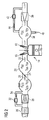
- a cylinder 14 has an inlet valve 16 and an outlet valve 18 which form the gas exchange valves.
- the valve overlap between the exhaust and inlet valves can be infinitely adjusted, for example, via an IVVT system (infinitely variable valve timing).
- the air mass entering the combustion chamber is described in the inlet 20 by the state variables pressure, temperature and volume (p IM , T IM , V IM ). From these quantities, a mass flow 22 in the cylinder (dm cyl / dt) is determined.
- the mass flow in the intake tract is regulated by a schematically illustrated throttle valve 24, through which a throttle air mass flow (dm THR / dt) occurs.
- the internal combustion engine is charged by a supercharger 28, which is driven by the turbine 30 arranged on the exhaust gas side.
- a return valve 32 is provided, through which a flowing back air mass flow (dm TCL / dt) flows back to the suction side of the supercharger.
- the charger is preceded by an air filter 36.
- an exhaust gas catalyst Downstream of the turbine 30 is an exhaust gas catalyst (not shown), from whose measured values the lambda value for the air / fuel mixture in the cylinder 14 is calculated.
- direct injection of fuel preferably takes place, which ensures that the beginning of the injection takes place after closing the outlet valve. This ensures that only fresh air without fuel is flushed to the exhaust side at a valve overlap.
- the additional purge air increases the mass flow through the exhaust-gas turbine 30 arranged on the exhaust gas side, as a result of which the achievable maximum power and the dynamic behavior of a turbocharger are markedly improved.
- the response of the exhaust gas turbocharger can be improved.
- the air mass flushed through the cylinder 14 essentially depends on the pressure difference p IM and p EX . This effect is also supported by possibly occurring resonances in the intake manifold, which can even lead to flushing even at lower intake manifold pressure.
- a deviation in the lambda signal from the nominal value may occur in the case of inaccurate prediction of the air mass remaining in the cylinder. This deviation is due to the back to the mass of fuel metered analog to the air mass.
- the injection quantity is also corrected correspondingly via lambda.
- this deviation is mainly caused by the exhaust back pressure, since the main context is based on the pressure gradient. For the control, therefore, the value of the exhaust backpressure is corrected on the basis of the measured lambda values.
Landscapes
- Engineering & Computer Science (AREA)
- Chemical & Material Sciences (AREA)
- Combustion & Propulsion (AREA)
- Mechanical Engineering (AREA)
- General Engineering & Computer Science (AREA)
- Output Control And Ontrol Of Special Type Engine (AREA)
- Electrical Control Of Air Or Fuel Supplied To Internal-Combustion Engine (AREA)
- Supercharger (AREA)
Abstract
Description
- Die vorliegende Erfindung betrifft ein Verfahren zur Steuerung einer Brennkraftmaschine mit einer Aufladevorrichtung.
- Aus
DE 100 50 059 A1 ist eine Zylinderluftfüllungssteuerung bekannt, die abhängig von einem geforderten Drehmoment Ein- und Auslassventile verstellt. Bei der Verwendung eines Turboladers wird daher vorgeschlagen, zur Vermeidung der Verzögerung bei einer Drehmomenterhöhung die Steuervorrichtung für Ein- und Auslassventile gleichzeitig zu öffnen, sodass bei positiver Druckdifferenz zwischen Ansaug- und Abgasseite ein Durchspülen von Ansaugluft zur Abgasseite auftritt. - Aus
DE 100 51 416 A1 ist ein Verfahren zur Steuerung einer Brennkraftmaschine bekannt, die eine elektronisch gesteuerte Einlass- und Auslassvorrichtung besitzt. Um eine rasche Veränderung des Luft-/Kraftstoffverhältnisses in den einzelnen Zylindern zu erzielen, wird die Auslassregelvorrichtung zur Steuerung des Luftstroms aus dem Ansaugkrümmer in den Zylinder eingesetzt. - Aus
DE 100 51 425 A1 ist ein Motorsteuersystem für einen Direkteinspritzer mit veränderlicher Ventilsteuerzeit bekannt. Bei dem Verfahren wird mit Hilfe einer Nockensteuerung die Frischluftladung in den Zylinder schneller gesteuert, als dies allein durch die Krümmerdynamik möglich ist. Das Verfahren erfasst ebenfalls die Änderung des Luft-/Kraftstoffverhältnisses in dem Zylinder und ändert die Ansteuerung der Auslasssteuervorrichtung dementsprechend. Zur Kompensation von fehlerhaften Berechnungen ist ein Krümmungsdrucksensor vorgesehen, der einen Krümmungsdruckfehler aus der Abweichung zwischen ermitteltem Krümmerdruck und aktuellem Krümmerdruck berechnet. - Aus
EP 1 243 779 A2 ist eine direkteinspritzende Brennkraftmaschine mit einem Turbolader zur Senkung des Verbrauchs insbesondere im Voll-Lastbetrieb bekannt, bei der zur Vermeidung von Klopfgeräuschen Restgas aus dem Zylinder herausgespült wird. Hierzu werden Einlass- und Auslassventil gleichzeitig geöffnet. - Den vorbeschriebenen Verfahren ist der Nachteil gemeinsam, dass durch den Spülvorgang kein direkter Zusammenhang zwischen der gemessenen (und daraus produzierten) Luftmasse, die in den Zylinder strömt und der tatsächlich im Zylinder verbleibenden Luftmasse besteht. Durch Berücksichtigung des sogenannten "Schluckverhaltens" des Zylinders wird versucht, dieses Problem zu lösen. Bei dem Schluckverhalten wird beispielsweise die in den Zylinder einströmende Frischluftmasse in Abhängigkeit von dem Saugrohr aufgetragen. Auch andere Betriebsgrößen können dabei berücksichtigt werden.
- Der vorliegenden Erfindung liegt die Aufgabe zugrunde, ein Verfahren bereitzustellen, das die Genauigkeit erhöht, mit der während und/oder nach einem Spülvorgang die tatsächlich im Zylinder verbleibende Luftmasse bestimmt werden kann.
- Erfindungsgemäß wird die Aufgabe durch ein Verfahren mit den Merkmalen gemäß Anspruch 1 gelöst. Vorteilhafte Ausgestaltung bilden den Gegenstand der Unteransprüche.
- Bei dem erfindungsgemäßen Verfahren zur Steuerung einer Brennkraftmaschine mit einer Aufladevorrichtung wird bei einer Abweichung des Lambda-Ist-Werts von einem vorberechneten Lambda-Wert für eine Ventilüberschneidung der Gaswechselventile der Wert für den Abgasgegendruck abhängig von der festgestellten Abweichung korrigiert. Mit einem korrigierten Wert für den Abgasgegendruck wird die Luftmasse in dem Zylinder bestimmt. Dem erfindungsgemäßen Verfahren liegt die Erkenntnis zugrunde, dass im Falle einer Abweichung des Lambda-Signals vom Sollwert die Ursache hauptsächlich durch einen fehlerhaften Wert für den Abgasgegendruck hervorgerufen wird. Das erfindungsgemäße Verfahren verfolgt also den Ansatz, eine Korrektur des volumetrischen Wirkungsgrades, sogenanntes Schluckverhalten, durch Adaption des während des Spülens auftretenden Abgasgegendrucks vorzunehmen. Das erfindungsgemäße Verfahren bietet den Vorteil, dass der ursächliche Grund für die Berechnung des Lambda-Ist-Werts zum Sollwert korrigiert wird, wodurch eine verbesserte Ansteuerung beispielsweise des Wastegates für den Turbolader erfolgen kann. Auch ist die Luftmasse und die Zylindermasse bei dem erfindungsgemäßen Verfahren genauer bestimmt, was zu einer besseren Einhaltung des vorberechneten Werts für das Verbrennungslambda führt.
- Die Korrektur des Werts für den Abgasgegendruck kann sowohl synchron als auch nachfolgend zu dem Spülvorgang erfolgen. Während des Spülvorgangs sind die Gaswechselventile gleichzeitig geöffnet. Bei der synchronen Korrektur wird der Wert des Abgasgegendrucks während der Ventilüberschneidung der Gaswechselventile geändert. Bei der nachfolgenden Korrektur wird der Wert des Abgasgegendrucks für die nachfolgenden Ventilüberschneidungen korrigiert.
- Die Korrektur für den Wert des Abgasgegendrucks erfolgt, wenn der Ansaugdruck im Saugrohr während der Ventilüberschneidung größer als der Abgasgegendruck ist. Bei dieser Bedingung erfolgt ein Spülen der Verbrennungsgase aus dem Brennraum durch einen Luftstrom, der von der Ansaugseite durch den Brennraum zur Abgasseite erfolgt. Zur Feststellung, ob die für das Spülen geeigneten Parameter vorliegen, wird der Quotient aus Saugrohrdruck und Abgasgegendruck mit einem vorbestimmten Schwellenwert verglichen. Liegt der Quotient oberhalb des Schwellenwerts, so liegt die Bedingung für ein Spülen vor. Alternativ oder zusätzlich kann als Bedingung für das Spülen auch die Differenz aus Saugrohrdruck und Abgasgegendruck mit einem vorbestimmten Schwellenwert verglichen werden.
- Der Wert für den Abgasgegendruck wird durch ein Steuermodul berechnet, das als Eingangsgrößen die Frischluftmasse, die Einspritzmasse und die Position eines Wastegates aufweist.
- Bei dem erfindungsgemäßen Verfahren erfolgt die Korrektur des Werts für den Abgasgegendruck dahingehend, dass der Wert vermindert wird, wenn der Lambda-Ist-Wert kleiner als der vorbestimmte Lambda-Sollwert ist. Geht man davon aus, dass die Abweichung im Lambda-Wert im Wesentlichen durch eine Abweichung in der Luftmasse auftritt, so bedeutet ein zu kleiner Lambda-Ist-Wert, dass insgesamt zu wenig Frischluft in dem Brennraum vorhanden war. Die einströmende Frischluft ist also unterschätzt worden, sodass bezogen auf den Abgasgegendruck dieser Wert zu hoch angesetzt wurde. Zur Korrektur wird also der Wert für den Abgasgegendruck vermindert. Aus derselben Überlegung heraus wird der Wert für den Abgasgegendruck erhöht, wenn der Lambda-Ist-Wert größer als der Lambda-Sollwert ist.
- Eine bevorzugte Ausführungsform des erfindungsgemäßen Verfahrens wird nachfolgend anhand der Figuren näher erläutert. Es zeigt:
- Figur 1
- den Druckverlauf von Saugrohrdruck und Abgasgegendruck über dem Kurbelwellenwinkel und
- Figur 2
- den Aufbau von Einlass- und Auslasskonfiguration einer Brennkraftmaschine mit Lader.
-
Figur 1 verdeutlicht beispielhaft den Druckverlauf abhängig von dem Kurbelwinkel, der inFigur 1 in 0,1° Schritten des Kurbelwellenwinkels aufgetragen wird. Der Saugrohrdruck 10 verläuft hierbei im Wesentlichen konstant. Anders entwickelt sich der Abgasgegendruck 12 über der Zeit, der im Bereich des geöffneten Gasauslassventils, bei einem Kurbelwellenwinkel von ungefähr 150° bis 300° ein deutliches Maximum annimmt. - Das Einlassventil ist in einem Winkelbereich von ungefähr 250° bis 360° geöffnet, sodass im Bereich von 250° bis ungefähr 300° eine Überlappung entsteht. In diesem Bereich ist der Saugrohrdruck 10 deutlich größer als der Abgasgegendruck, sodass Frischluft aus dem Ansaugtrakt durch den Brennraum in den Abgastrakt gespült wird. (Der Spülvorgang wird auch als
- Scavenging bezeichnet).
- Diese Funktionsweise wird anhand des in
Figur 2 wiedergegebenen schematischen Aufbaus deutlich. Ein Zylinder 14 besitzt ein Einlassventil 16 und ein Auslassventil 18, die die Gaswechselventile bilden. Die Ventilüberschneidung zwischen Auslass- und Einlassventil kann beispielsweise über ein IVVT-System (infinitely variable valve timing) stufenlos eingestellt werden. - Die in den Brennraum eintretende Luftmasse wird in dem Einlass 20 durch die Zustandsgrößen Druck, Temperatur und Volumen (pIM, TIM, VIM) beschrieben. Aus diesen Größen wird ein Massestrom 22 in den Zylinder (dmcyl/dt) bestimmt.
- Reguliert wird der Massenstrom in dem Einlasstrakt durch eine schematisch dargestellte Drosselklappe 24, durch die ein Drosselklappenluftmassenstrom (dmTHR/dt) tritt.
- Aufgeladen wird die Brennkraftmaschine durch einen Lader 28, der durch die abgasseitig angeordnete Turbine 30 angetrieben wird. In einem Bypass zu dem Lader 28 ist ein Rücklaufventil 32 vorgesehen, durch das ein rückfließender Luftmassestrom (dmTCL/dt) zurück auf die Ansaugseite des Laders fließt. Beispielhaft ist dem Lader noch ein Luftfilter 36 vorgeordnet.
- Abgasseitig von dem Zylinder 14 wird der Zustand der Abgase durch Druck, Temperatur und Volumen (pEX, TEX, VEX) beschrieben. Dem Abgas kann noch ein sekundärer Luftstrom 40 zugeführt werden. Über ein Wastegate 42 kann ein Luftmassenstrom (dmWG/dt) an der Turbine 30 vorbeigeführt werden.
- Stromabwärts von der Turbine 30 befindet sich ein Abgaskatalysator (nicht dargestellt), aus dessen Messwerten der Lambda-Wert für das Luft-/Kraftstoffgemisch in dem Zylinder 14 berechnet wird.
- Bei der dargestellten Ein- und Auslasskonfiguration erfolgt bevorzugt eine Direkteinspritzung von Kraftstoff, die sicherstellt, dass der Beginn der Einspritzung nach Schließen des Auslassventils erfolgt. Damit wird sichergestellt, dass nur Frischluft ohne Kraftstoff zur Abgasseite bei einer Ventilüberschneidung gespült wird.
- Durch die zusätzliche Spülluft wird der Massenstrom durch die abgasseitig angeordnete Abgasturbine 30 erhöht, wodurch sich die erzielbare Maximalleistung und das dynamische Verhalten eines Turboladers deutlich verbessern. So kann insbesondere für geringe Motordrehzahlen das Ansprechverhalten des Abgasturboladers verbessert werden.
- Im volllastnahen Betrieb einer aufgeladenen Brennkraftmaschine bewirkt die bei einer Ventilüberschneidung zur Abgasseite gespülte Frischluft einer Erhöhung des Durchsatz durch die Brennkraftmaschine, ohne an der Verbrennung teilzunehmen. Es treten dabei insbesondere die folgenden Vorteile für das Betriebsverhalten auf:
- ● Bei einem Lambda-Wert λEX=1 findet bei Spülluft eine Verbrennung im Zylinder mit einem Lambda-Wert λCYL<1 statt. Durch die Verbrennung im Fetten wird die Klopfneigung reduziert.
- ● λCYL<1 bewirkt einen sehr hohen CO- und HC-Anteil im Abgas. Gleichzeitig sorgt der Spülluftanteil für einen hohen Restsauerstoffgehalt und bewirkt so einen internen Sekundärlufteffekt. Die resultierende Abgaszusammensetzung bewirkt eine hohe Exothermie im Abgaskatalysator und beschleunigt so seine Aufheizung.
- ● Durch Spülen wird der Restgasanteil im Brennraum und somit die Klopfneigung vermindert. Die Minimierung des Restgasanteils ist bei Betrieb nahe der Voll-Last von entscheidender Bedeutung, um eine maximale Zylinderfüllung zu erreichen und diese Füllung auch effektiv, das heißt mit günstiger Verbrennungsschwerpunktlage, umzusetzen.
- ● Die zusätzliche Spülluftmenge erhöht den Massenstrom durch die Turbine, wodurch bei niedrigen Motordrehzahlen sowohl das Ansprechverhalten, als auch die erreichbare Maximalleistung gesteigert werden können.
- Die durch den Zylinder 14 gespülte Luftmasse hängt im Wesentlichen von der Druckdifferenz pIM und pEX ab. Unterstützt wird dieser Effekt auch durch möglicherweise auftretende Resonanzen im Saugrohr, die sogar bei niedrigerem Saugrohrdruck bereits zum Spülen führen können. Im Falle des Spülens kann bei ungenauer Prädiktion der im Zylinder verbleibenden Luftmasse eine Abweichung im Lambda-Signal vom Sollwert auftreten. Diese Abweichung geht ursächlich auf die analog zur Luftmasse zugemessene Kraftstoffmasse zurück. Im Falle einer Abweichung der Luftmasse vom Prädiktionswert wird auch die Einspritzmenge entsprechend über Lambda korrigiert. Diese Abweichung wird aber hauptsächlich durch den Abgasgegendruck hervorgerufen, da der Hauptzusammenhang auf dem Druckgefälle beruht. Für die Steuerung wird daher der Wert des Abgasgegendrucks aufgrund der gemessenen Lambda-Werte korrigiert.
- Mit dem korrigierten Wert für den Abgasgegendruck ist auch eine genauere Ansteuerung des Wastegates 42 für den Turbolader 30 möglich.
Claims (9)
- Verfahren zur Steuerung einer Brennkraftmaschine mit einer Aufladevorrichtung (28, 30), bei dem- eine Abweichung des Lambda-Ist-Wertes von einem vorberechneten Lambda-Wert festgestellt wird,- für eine Ventilüberschneidung, bei der Gaswechselventile des Brennraums gleichzeitig geöffnet sind, der Wert für den Abgasgegendruck abhängig von der festgestellten Abweichung korrigiert wird und- mit dem korrigierten Wert für den Abgasgegendruck die Luftmasse in dem Zylinder bestimmt wird.
- Verfahren nach Anspruch 1, dadurch gekennzeichnet, dass die Korrektur für den Wert des Abgasgegendrucks erfolgt, wenn der Ansaugdruck im Saugrohr während der Ventilüberschneidung größer als der Abgasgegendruck ist.
- Verfahren nach Anspruch 1 oder 2, dadurch gekennzeichnet, dass die Korrektur für den Wert des Abgasgegendrucks erfolgt, wenn der Quotient aus Saugrohrdruck und Abgasgegendruck größer als ein vorbestimmter Schwellwert ist.
- Verfahren nach Anspruch 1 oder 2, dadurch gekennzeichnet, dass die Korrektur für den Wert des Abgasgegendrucks erfolgt, wenn die Differenz aus Saugrohrdruck und Abgasgegendruck einen vorbestimmten Schwellenwert überschreitet.
- Verfahren nach einem der Ansprüche 1 bis 4, dadurch gekennzeichnet, dass der Wert für den Abgasgegendruck durch ein Steuermodul berechnet wird, das als Eingangsgröße die Frischluftmasse, die Einspritzmasse und die Position eines Wastegates (42) aufweist.
- Verfahren nach einem der Ansprüche 1 bis 5, dadurch gekennzeichnet, dass der Wert für den Abgasgegendruck vermindert wird, wenn der Lambda-Ist-Wert kleiner als der Lambda-soll-wert ist.
- Verfahren nach einem der Ansprüche 1 bis 5, dadurch gekennzeichnet, dass der Wert für den Abgasgegendruck erhöht wird, wenn der Lambda-Ist-Wert größer als der Lambda-Soll-Wert ist.
- Verfahren nach einem5der Ansprüche 1 bis 7, dadurch gekennzeichnet, dass die Korrektur für den Wert des Abgasgegendrucks während der Ventilüberschneidung erfolgt.
- Verfahren nach einem der Ansprüche 1 bis 7, dadurch gekennzeichnet, dass die Korrektur für den Wert des Abgasgegendrucks für die nachfolgende Ventilüberschneidung erfolgt.
Applications Claiming Priority (2)
| Application Number | Priority Date | Filing Date | Title |
|---|---|---|---|
| DE102004030605A DE102004030605B3 (de) | 2004-06-24 | 2004-06-24 | Verfahren zur Steuerung einer Brennkraftmaschine mit einer Aufladevorrichtung |
| PCT/EP2005/051436 WO2006000472A1 (de) | 2004-06-24 | 2005-03-30 | Verfahren zur steuerung einer brennkraftmaschine mit einer aufladevorrichtung |
Publications (2)
| Publication Number | Publication Date |
|---|---|
| EP1759104A1 EP1759104A1 (de) | 2007-03-07 |
| EP1759104B1 true EP1759104B1 (de) | 2008-05-07 |
Family
ID=34962391
Family Applications (1)
| Application Number | Title | Priority Date | Filing Date |
|---|---|---|---|
| EP05728195A Expired - Lifetime EP1759104B1 (de) | 2004-06-24 | 2005-03-30 | Verfahren zur steuerung einer brennkraftmaschine mit einer aufladevorrichtung |
Country Status (5)
| Country | Link |
|---|---|
| US (1) | US7597092B2 (de) |
| EP (1) | EP1759104B1 (de) |
| KR (1) | KR100809122B1 (de) |
| DE (2) | DE102004030605B3 (de) |
| WO (1) | WO2006000472A1 (de) |
Cited By (1)
| Publication number | Priority date | Publication date | Assignee | Title |
|---|---|---|---|---|
| DE102017125575A1 (de) | 2017-11-02 | 2019-05-02 | Iav Gmbh Ingenieurgesellschaft Auto Und Verkehr | Brennkraftmaschine mit Zylinderspülung und Spülluftrückführung |
Families Citing this family (13)
| Publication number | Priority date | Publication date | Assignee | Title |
|---|---|---|---|---|
| DE102006013501B4 (de) * | 2006-03-23 | 2009-12-31 | Continental Automotive Gmbh | Verfahren und Vorrichtung zum Betreiben einer Brennkraftmaschine |
| DE102006042872B4 (de) * | 2006-09-13 | 2010-02-25 | Ford Global Technologies, LLC, Dearborn | Verfahren zur Bestimmung des Abgasgegendrucks stromaufwärts einer Turbine eines Abgasturboladers |
| US8209109B2 (en) * | 2007-07-13 | 2012-06-26 | Ford Global Technologies, Llc | Method for compensating an operating imbalance between different banks of a turbocharged engine |
| DE102007039613B4 (de) * | 2007-08-22 | 2014-10-09 | Continental Automotive Gmbh | Verfahren zum Betreiben einer Brennkraftmaschine und Steuer- und Regeleinrichtung |
| DE102007043440B3 (de) | 2007-09-12 | 2009-04-02 | Continental Automotive Gmbh | Verfahren zum Ermitteln einer in einem Zylinder einer Brennkraftmaschine eingefangenen Luftmasse |
| FR2926850B1 (fr) * | 2008-01-28 | 2010-03-05 | Inst Francais Du Petrole | Procede de balayage des gaz brules residuels avec une double levee de soupape d'admission d'un moteur a combustion interne suralimente a injection directe, notamment de type diesel |
| DE102011114065A1 (de) * | 2011-09-22 | 2013-03-28 | Daimler Ag | Verfahren zum Betreiben einer Brennkraftmaschine |
| EP2927469A4 (de) * | 2012-11-29 | 2016-07-13 | Toyota Motor Co Ltd | Steuerungsvorrichtung für einen motor mit lader |
| DE102013009896A1 (de) * | 2013-06-13 | 2014-12-18 | Volkswagen Aktiengesellschaft | Brennkraftmaschine und Verfahren zum Betreiben einer solchen Brennkraftmaschine |
| WO2015013696A1 (en) * | 2013-07-26 | 2015-01-29 | Pinnacle Engines, Inc. | Early exhaust valve opening for improved catalyst light off |
| JP6202063B2 (ja) * | 2015-09-15 | 2017-09-27 | トヨタ自動車株式会社 | 内燃機関の制御装置 |
| DE102016218687B4 (de) | 2016-09-28 | 2024-05-16 | Volkswagen Aktiengesellschaft | Verfahren zur Erkennung eines Beladungsgrades eines Partikelfilters |
| DE102017203213B3 (de) * | 2017-02-28 | 2018-07-26 | Continental Automotive Gmbh | Verfahren und Vorrichtung zur Ventilhubumschaltsteuerung eines Verbrennungsmotors |
Family Cites Families (13)
| Publication number | Priority date | Publication date | Assignee | Title |
|---|---|---|---|---|
| JPS61149536A (ja) | 1984-12-25 | 1986-07-08 | Honda Motor Co Ltd | 過給機を備えた内燃エンジンの動作制御量制御方法 |
| US5051909A (en) * | 1989-09-15 | 1991-09-24 | General Motors Corporation | Method and means for determining exhaust backpressure in a crankcase scavenged two-stoke engine |
| JP2600453B2 (ja) * | 1990-07-20 | 1997-04-16 | 三菱自動車工業株式会社 | 空燃比センサ出力の補正方法 |
| US6273076B1 (en) * | 1997-12-16 | 2001-08-14 | Servojet Products International | Optimized lambda and compression temperature control for compression ignition engines |
| US6250283B1 (en) * | 1999-10-18 | 2001-06-26 | Ford Global Technologies, Inc. | Vehicle control method |
| US6470869B1 (en) * | 1999-10-18 | 2002-10-29 | Ford Global Technologies, Inc. | Direct injection variable valve timing engine control system and method |
| US6560527B1 (en) * | 1999-10-18 | 2003-05-06 | Ford Global Technologies, Inc. | Speed control method |
| DE19948136A1 (de) * | 1999-10-07 | 2001-04-12 | Volkswagen Ag | Verfahren zur Bestimmung eines Abgasgegendruckes an einer Turbine |
| US6393903B1 (en) * | 1999-12-10 | 2002-05-28 | Delphi Technologies, Inc. | Volumetric efficiency compensation for dual independent continuously variable cam phasing |
| JP2002276418A (ja) * | 2001-03-23 | 2002-09-25 | Hitachi Ltd | ターボ過給機付き筒内噴射エンジン及びその制御方法 |
| DE10256474B3 (de) | 2002-12-03 | 2004-05-19 | Siemens Ag | Verfahren zum Steuern einer mit Kraftstoffdirekteinspritzung arbeitenden Brennkraftmaschine |
| DE10259052B3 (de) * | 2002-12-17 | 2004-04-01 | Siemens Ag | Verfahren zum Aufheizen eines Abgaskatalysators einer mit Kraftstoff-Direkteinspritzung arbeitenden Brennkraftmaschine |
| DE10300794B4 (de) * | 2003-01-13 | 2015-07-02 | Robert Bosch Gmbh | Verfahren zum Betreiben eines Verbrennungsmotors |
-
2004
- 2004-06-24 DE DE102004030605A patent/DE102004030605B3/de not_active Expired - Fee Related
-
2005
- 2005-03-30 KR KR1020067004152A patent/KR100809122B1/ko not_active Expired - Fee Related
- 2005-03-30 DE DE502005004023T patent/DE502005004023D1/de not_active Expired - Lifetime
- 2005-03-30 EP EP05728195A patent/EP1759104B1/de not_active Expired - Lifetime
- 2005-03-30 WO PCT/EP2005/051436 patent/WO2006000472A1/de not_active Ceased
- 2005-03-30 US US10/570,007 patent/US7597092B2/en not_active Expired - Lifetime
Cited By (2)
| Publication number | Priority date | Publication date | Assignee | Title |
|---|---|---|---|---|
| DE102017125575A1 (de) | 2017-11-02 | 2019-05-02 | Iav Gmbh Ingenieurgesellschaft Auto Und Verkehr | Brennkraftmaschine mit Zylinderspülung und Spülluftrückführung |
| DE102017125575B4 (de) | 2017-11-02 | 2022-02-03 | Iav Gmbh Ingenieurgesellschaft Auto Und Verkehr | Brennkraftmaschine mit Zylinderspülung und Spülluftrückführung |
Also Published As
| Publication number | Publication date |
|---|---|
| DE102004030605B3 (de) | 2006-02-09 |
| EP1759104A1 (de) | 2007-03-07 |
| US7597092B2 (en) | 2009-10-06 |
| KR100809122B1 (ko) | 2008-03-03 |
| US20080190405A1 (en) | 2008-08-14 |
| KR20060060713A (ko) | 2006-06-05 |
| WO2006000472A1 (de) | 2006-01-05 |
| DE502005004023D1 (de) | 2008-06-19 |
Similar Documents
| Publication | Publication Date | Title |
|---|---|---|
| EP1576268B1 (de) | Verfahren zum aufheizen eines abgaskatalysators einer mit kraftstoff-direkteinspritzung arbeitenden brennkraftmaschine | |
| DE102014019359B4 (de) | Dieselmotor, Kraftstoffeinspritzsteuer- bzw. Regelvorrichtung hierfür, Verfahren zum Steuern bzw. Regeln eines Dieselmotors und Computerprogrammerzeugnis | |
| DE112012004907B4 (de) | Steuervorrichtung für Verbrennungsmotor | |
| EP1759104B1 (de) | Verfahren zur steuerung einer brennkraftmaschine mit einer aufladevorrichtung | |
| DE102016221847A1 (de) | Verfahren zum Betreiben eines Verbrennungsmotors nach einem Kaltstart | |
| DE102005005676A1 (de) | Verstärkungsdruckschätzvorrichtung für eine Brennkraftmaschine mit einer Ladevorrichtung | |
| DE102011005225A1 (de) | Anormalitätsdiagnosevorrichtung eines Verbrennungsmotors mit einem Turbolader | |
| EP1567760B1 (de) | Verfahren zum steuern einer mit kraftstoffdirekteinspritzung arbeitenden brennkraftmaschine | |
| DE102014013675B4 (de) | Abgasrezirkulations-Regel- bzw. Steuervorrichtung, Motor, Verfahren zum Regeln bzw. Steuern einer EGR Vorrichtung und Computerprogrammprodukt | |
| DE102009000933A1 (de) | Kraftstoffeinspritzsteuerungsvorrichtung einer Direkteinspritzbrennkraftmaschine mit Aufladegerät | |
| DE102010043800A1 (de) | Steuervorrichtung für eine Brennkraftmaschine mit einem Turbolader | |
| DE102018105636A1 (de) | Abgassteuerungsvorrichtung für Verbrennungskraftmaschine | |
| DE102004030604B3 (de) | Verfahren zur Bestimmung der Luftmasse in einem Zylinder | |
| EP3040543B1 (de) | Verfahren zur steuerung der temperatur der abgase eines turboverbrennungsmotors | |
| DE10303705B4 (de) | Verfahren zum Betreiben einer mit Kraftstoffdirekteinspritzung arbeitenden Brennkraftmaschine | |
| DE10217589B4 (de) | Verfahren zum Aufheizen eines Katalysators im Abgastrakt einer Brennkraftmaschine | |
| DE10066432B4 (de) | Vorrichtung zum Erfassen einer Fehlfunktion eines Abgassystems des Motors | |
| WO2018046212A1 (de) | Verfahren und vorrichtung zur steuerung der nach einem gaswechselvorgang im zylinder einer brennkraftmaschine verbleibenden restgasmasse und/oder der während eines gaswechselvorgangs in den abgaskrümmer der brennkraftmaschine gespülten spülluftmasse | |
| DE102010030496B4 (de) | Steuervorrichtung für Maschine mit Direkteinspritzung | |
| DE102016110287A1 (de) | Steuerungsgerät und steuerungsverfahren für verbrennungsmotor | |
| DE102005015999A1 (de) | Verfahren und Vorrichtung zur Katalysatoraufheizung | |
| DE102020202892A1 (de) | Verfahren zur Vorsteuerung eines Kraftstoff-Luft-Gemisches für mindestens einen Brennraum einer Verbrennungskraftmaschine | |
| DE102006029370A1 (de) | Verfahren zur Steigerung des Ladedruckaufbaus bei aufgeladenen Verbrennungskraftmaschinen | |
| EP1591646B1 (de) | Betriebsverfahren für einen Ottomotor mit Ventilüberlappung | |
| DE102006031254A1 (de) | Verfahren und Steuergerät zum Betreiben eines Verbrennungsmotors mit überströmender Luft |
Legal Events
| Date | Code | Title | Description |
|---|---|---|---|
| PUAI | Public reference made under article 153(3) epc to a published international application that has entered the european phase |
Free format text: ORIGINAL CODE: 0009012 |
|
| 17P | Request for examination filed |
Effective date: 20060119 |
|
| AK | Designated contracting states |
Kind code of ref document: A1 Designated state(s): DE FR GB |
|
| RBV | Designated contracting states (corrected) |
Designated state(s): DE FR GB |
|
| DAX | Request for extension of the european patent (deleted) | ||
| GRAP | Despatch of communication of intention to grant a patent |
Free format text: ORIGINAL CODE: EPIDOSNIGR1 |
|
| GRAS | Grant fee paid |
Free format text: ORIGINAL CODE: EPIDOSNIGR3 |
|
| RAP1 | Party data changed (applicant data changed or rights of an application transferred) |
Owner name: VDO AUTOMOTIVE AG |
|
| GRAA | (expected) grant |
Free format text: ORIGINAL CODE: 0009210 |
|
| AK | Designated contracting states |
Kind code of ref document: B1 Designated state(s): DE FR GB |
|
| REG | Reference to a national code |
Ref country code: GB Ref legal event code: FG4D Free format text: NOT ENGLISH |
|
| REF | Corresponds to: |
Ref document number: 502005004023 Country of ref document: DE Date of ref document: 20080619 Kind code of ref document: P |
|
| RAP2 | Party data changed (patent owner data changed or rights of a patent transferred) |
Owner name: CONTINENTAL AUTOMOTIVE GMBH |
|
| PLBE | No opposition filed within time limit |
Free format text: ORIGINAL CODE: 0009261 |
|
| STAA | Information on the status of an ep patent application or granted ep patent |
Free format text: STATUS: NO OPPOSITION FILED WITHIN TIME LIMIT |
|
| 26N | No opposition filed |
Effective date: 20090210 |
|
| PGFP | Annual fee paid to national office [announced via postgrant information from national office to epo] |
Ref country code: GB Payment date: 20090325 Year of fee payment: 5 |
|
| PGFP | Annual fee paid to national office [announced via postgrant information from national office to epo] |
Ref country code: FR Payment date: 20090312 Year of fee payment: 5 |
|
| GBPC | Gb: european patent ceased through non-payment of renewal fee |
Effective date: 20100330 |
|
| REG | Reference to a national code |
Ref country code: FR Ref legal event code: ST Effective date: 20101130 |
|
| PG25 | Lapsed in a contracting state [announced via postgrant information from national office to epo] |
Ref country code: FR Free format text: LAPSE BECAUSE OF NON-PAYMENT OF DUE FEES Effective date: 20100331 |
|
| PG25 | Lapsed in a contracting state [announced via postgrant information from national office to epo] |
Ref country code: GB Free format text: LAPSE BECAUSE OF NON-PAYMENT OF DUE FEES Effective date: 20100330 |
|
| REG | Reference to a national code |
Ref country code: DE Ref legal event code: R084 Ref document number: 502005004023 Country of ref document: DE |
|
| REG | Reference to a national code |
Ref country code: DE Ref legal event code: R081 Ref document number: 502005004023 Country of ref document: DE Owner name: VITESCO TECHNOLOGIES GMBH, DE Free format text: FORMER OWNER: CONTINENTAL AUTOMOTIVE GMBH, 30165 HANNOVER, DE |
|
| REG | Reference to a national code |
Ref country code: DE Ref legal event code: R081 Ref document number: 502005004023 Country of ref document: DE Owner name: VITESCO TECHNOLOGIES GMBH, DE Free format text: FORMER OWNER: VITESCO TECHNOLOGIES GMBH, 30165 HANNOVER, DE |
|
| PGFP | Annual fee paid to national office [announced via postgrant information from national office to epo] |
Ref country code: DE Payment date: 20230331 Year of fee payment: 19 |
|
| P01 | Opt-out of the competence of the unified patent court (upc) registered |
Effective date: 20230530 |
|
| REG | Reference to a national code |
Ref country code: DE Ref legal event code: R119 Ref document number: 502005004023 Country of ref document: DE |
|
| PG25 | Lapsed in a contracting state [announced via postgrant information from national office to epo] |
Ref country code: DE Free format text: LAPSE BECAUSE OF NON-PAYMENT OF DUE FEES Effective date: 20241001 |
|
| PG25 | Lapsed in a contracting state [announced via postgrant information from national office to epo] |
Ref country code: DE Free format text: LAPSE BECAUSE OF NON-PAYMENT OF DUE FEES Effective date: 20241001 |