EP1757888B1 - Anordnung zweier Wärmeübertrager - Google Patents
Anordnung zweier Wärmeübertrager Download PDFInfo
- Publication number
- EP1757888B1 EP1757888B1 EP20060015543 EP06015543A EP1757888B1 EP 1757888 B1 EP1757888 B1 EP 1757888B1 EP 20060015543 EP20060015543 EP 20060015543 EP 06015543 A EP06015543 A EP 06015543A EP 1757888 B1 EP1757888 B1 EP 1757888B1
- Authority
- EP
- European Patent Office
- Prior art keywords
- heat exchanger
- header
- designed
- soldered
- holder
- Prior art date
- Legal status (The legal status is an assumption and is not a legal conclusion. Google has not performed a legal analysis and makes no representation as to the accuracy of the status listed.)
- Not-in-force
Links
- 239000002826 coolant Substances 0.000 claims description 44
- 229910052782 aluminium Inorganic materials 0.000 claims description 3
- 238000002485 combustion reaction Methods 0.000 claims description 3
- XAGFODPZIPBFFR-UHFFFAOYSA-N aluminium Chemical compound [Al] XAGFODPZIPBFFR-UHFFFAOYSA-N 0.000 claims description 2
- 238000010276 construction Methods 0.000 claims 1
- 239000000463 material Substances 0.000 claims 1
- 239000007787 solid Substances 0.000 claims 1
- 239000003990 capacitor Substances 0.000 description 33
- 239000003507 refrigerant Substances 0.000 description 7
- 238000004519 manufacturing process Methods 0.000 description 4
- 238000003780 insertion Methods 0.000 description 3
- 230000037431 insertion Effects 0.000 description 3
- 238000004378 air conditioning Methods 0.000 description 2
- 238000001816 cooling Methods 0.000 description 2
- 238000009434 installation Methods 0.000 description 2
- 229910052751 metal Inorganic materials 0.000 description 2
- 239000002184 metal Substances 0.000 description 2
- 238000004873 anchoring Methods 0.000 description 1
- 230000001627 detrimental effect Effects 0.000 description 1
- 230000008030 elimination Effects 0.000 description 1
- 238000003379 elimination reaction Methods 0.000 description 1
- 238000002347 injection Methods 0.000 description 1
- 239000007924 injection Substances 0.000 description 1
- 238000001746 injection moulding Methods 0.000 description 1
- 238000005476 soldering Methods 0.000 description 1
- 239000000243 solution Substances 0.000 description 1
Images




Classifications
-
- F—MECHANICAL ENGINEERING; LIGHTING; HEATING; WEAPONS; BLASTING
- F28—HEAT EXCHANGE IN GENERAL
- F28F—DETAILS OF HEAT-EXCHANGE AND HEAT-TRANSFER APPARATUS, OF GENERAL APPLICATION
- F28F21/00—Constructions of heat-exchange apparatus characterised by the selection of particular materials
- F28F21/06—Constructions of heat-exchange apparatus characterised by the selection of particular materials of plastics material
- F28F21/067—Details
-
- F—MECHANICAL ENGINEERING; LIGHTING; HEATING; WEAPONS; BLASTING
- F28—HEAT EXCHANGE IN GENERAL
- F28D—HEAT-EXCHANGE APPARATUS, NOT PROVIDED FOR IN ANOTHER SUBCLASS, IN WHICH THE HEAT-EXCHANGE MEDIA DO NOT COME INTO DIRECT CONTACT
- F28D1/00—Heat-exchange apparatus having stationary conduit assemblies for one heat-exchange medium only, the media being in contact with different sides of the conduit wall, in which the other heat-exchange medium is a large body of fluid, e.g. domestic or motor car radiators
- F28D1/02—Heat-exchange apparatus having stationary conduit assemblies for one heat-exchange medium only, the media being in contact with different sides of the conduit wall, in which the other heat-exchange medium is a large body of fluid, e.g. domestic or motor car radiators with heat-exchange conduits immersed in the body of fluid
- F28D1/04—Heat-exchange apparatus having stationary conduit assemblies for one heat-exchange medium only, the media being in contact with different sides of the conduit wall, in which the other heat-exchange medium is a large body of fluid, e.g. domestic or motor car radiators with heat-exchange conduits immersed in the body of fluid with tubular conduits
- F28D1/0408—Multi-circuit heat exchangers, e.g. integrating different heat exchange sections in the same unit or heat exchangers for more than two fluids
- F28D1/0426—Multi-circuit heat exchangers, e.g. integrating different heat exchange sections in the same unit or heat exchangers for more than two fluids with units having particular arrangement relative to the large body of fluid, e.g. with interleaved units or with adjacent heat exchange units in common air flow or with units extending at an angle to each other or with units arranged around a central element
- F28D1/0435—Combination of units extending one behind the other
-
- F—MECHANICAL ENGINEERING; LIGHTING; HEATING; WEAPONS; BLASTING
- F28—HEAT EXCHANGE IN GENERAL
- F28F—DETAILS OF HEAT-EXCHANGE AND HEAT-TRANSFER APPARATUS, OF GENERAL APPLICATION
- F28F9/00—Casings; Header boxes; Auxiliary supports for elements; Auxiliary members within casings
- F28F9/001—Casings in the form of plate-like arrangements; Frames enclosing a heat exchange core
- F28F9/002—Casings in the form of plate-like arrangements; Frames enclosing a heat exchange core with fastening means for other structures
-
- F—MECHANICAL ENGINEERING; LIGHTING; HEATING; WEAPONS; BLASTING
- F28—HEAT EXCHANGE IN GENERAL
- F28F—DETAILS OF HEAT-EXCHANGE AND HEAT-TRANSFER APPARATUS, OF GENERAL APPLICATION
- F28F2275/00—Fastening; Joining
- F28F2275/08—Fastening; Joining by clamping or clipping
- F28F2275/085—Fastening; Joining by clamping or clipping with snap connection
Definitions
- the invention relates to an arrangement of two heat exchangers according to the subject matter of the earlier patent application of the Applicant DE 103 48 701 A1 ,
- the DE-A 198 57 512 was a cooling module, consisting of a coolant radiator, a refrigerant condenser and a fan cowl known, which are connected together to form a structural unit.
- the coolant radiator arranged in the middle of the carrier of the other two components, which are held by molded on the coolant box of the radiator guide rails.
- the capacitor has additional fastening means in the form of metal profiles, which are held on the one hand in the slide rails and on the other hand fixed to headers of the capacitor by soldering.
- the soldered holder can be clipped on the other heat exchanger; thus the advantage of a quick installation is achieved.
- one of the soldered holder is designed as a block connection.
- the block connection receives a second function, namely as a holder and thus eliminates an additional holder to be soldered.
- the soldered holder are designed as a fixed bearing, while the attachment points are formed on the opposite side as a floating bearing.
- the injection-molded holding means are formed as half-shells with a U-profile, wherein the U-profile has an open side facing in the direction of the heat exchanger block.
- the headers are frontally extended, so that the extended pipe ends can be inserted from the outside into the U-profiles.
- the two half shells form a pivot bearing for the manifold so that the heat exchanger can be folded in after insertion and locked by clipping on the other side.
- the U-profiles are closed by side walls, which bear against the end faces of the headers.
- an elastic tongue is provided on one of the two side walls, which is supported on an end face of the collecting tube.
- elastic ribs are arranged between the half shells, which are supported on the manifold.
- the injection molded onto the manifolds holding means are formed as side cheeks, ie as substantially planar holding surfaces which comprise the end faces of a manifold and thus cause a fixation of the manifold in the direction of its longitudinal axis.
- retaining tabs are molded onto the collecting box, which protrude from the collecting box, pass through the heat exchanger block and comprise the collecting tube on the opposite side.
- an elastic tongue for tolerance and expansion compensation is provided on one of the two side cheeks.
- one of the two heat exchangers is designed as a coolant radiator with coolant tanks made of plastic, while the other is designed as a brazed refrigerant condenser in Ganzaluminiumbauweise.
- the fasteners in the form of U-profiles can be sprayed on the coolant boxes due to their simple form with low tooling costs.
- the capacitor can be easily inserted with its substantially round headers in the U-profiles and pivoted about the longitudinal axis due to the round shape of the manifolds.
- d. H. Holders soldered to the second header can be clipped onto the other coolant box with molded locking means.
- the capacitor is thus folded into the U-profiles after insertion and clipped. This is a simple and quick installation.
- a further advantage is that a capacitor in each case via a block connection, d. H. a soldered flange for refrigerant supply and discharge has. This flange can be used as a holding means or as an anchoring part for a fixed bearing, which is clipped with the coolant box. In this respect, so only one additional holder needs to be soldered, which keeps the extra effort for fasteners low.
- At least one of the two heat exchangers can be used as a charge air cooler or as an oil cooler.
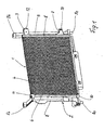
- Fig. 1 shows an inventive arrangement of a front mounted in the drawing capacitor and a coolant radiator 2 arranged behind, which are mounted as a unit in a front engine compartment of a motor vehicle, not shown, similar to that in the aforementioned earlier patent application, which hereby incorporated into the disclosure of the is included in the present application is described.
- the coolant radiator 2 is connected in a manner not shown to a coolant circuit of an internal combustion engine of the motor vehicle, while the capacitor 1 is connected via a so-called block connection 3 in a manner not shown to a refrigerant circuit of an air conditioning system of the motor vehicle.
- the condenser 1 is designed as a brazed all-aluminum heat exchanger with a network 4 and lateral headers 5, 6, wherein at the right manifold 5 - in addition to the block terminal 3 - a capacitor holder 7 is soldered.
- the radiator 2 has two collection or coolant boxes 8, 9 made of plastic, between which there is the network of the radiator, which is covered by the condensate network 4 and therefore not visible.
- the cooler 2 is designed as a cross-flow cooler and has at its coolant boxes 8, 9, two lower mounting pins 8a, 9a and two upper mounting arms 8b, 9b, via which the radiator 2 is fixed in the vehicle, not shown.
- the condenser 1 is connected via the block connection 3 and the soldered holder 7 to the coolant box 9 in each case by a clip connection 12, 13.
- the capacitor 1 is thus attached to the radiator 2 at four points, wherein the two arranged on the right side of the capacitor 1 clip connections 12, 13 are designed as a fixed bearing and arranged on the left side U-profiles 10, 11 as a floating bearing. Different elongations of the capacitor network 4 and the (non-visible) radiator network can thus be compensated, so that it can not lead to thermally induced stresses in the heat exchangers 1, 2.
- Fig. 2 shows a corner cutout Fig. 1 with the upper holder 11, which receives the upper end of the manifold 6 of the capacitor 1 in it.
- the U-profile of the holder 11 is closed at the top by a side wall 11a, on which an elastic tongue 11b is formed, which is visible in the holder 11 through a cutout 11c.
- the elastic tongue 11b bears resiliently against the end face of the collecting tube 6.
- Fig. 3 shows a corner cutout Fig. 1 with the lower holder 10, which receives the lower end of the manifold 6.
- Fig. 4 shows the lower holder 10, molded on the coolant box 8 with a U-profile 10a, which is closed at the bottom by a side wall 10b. On this side wall 10b rests - what in Fig. 4 not shown - the end face of the manifold 6.
- the U-profile 10a is in the direction of heat exchanger block (not shown here) open.
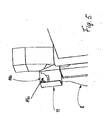
- Fig. 5 shows the upper holder 11, molded on the coolant box 8, with resilient tongue 11 b, which protrudes from the upper side wall 11a and forms a Federelemerit, which presses on the end face of the collecting tube 6, not shown here.
- Fig. 6 shows the coolant box 8 as a single part with the two molded holders 10, 11 at the bottom and top of the coolant box 8. It can be clearly seen in this illustration that both U-profiles of the half-shell-shaped holder 10, 11 are open to (not shown) heat exchanger block out
- the upper holder 11 has a U-profile 11d with an open side 11e.
- two flexible ribs 14, 15 are molded on the side wall of the coolant box 8, which resiliently bear against the longitudinal side of the collection tube 6, not shown here, received by the holders 10, 11. This fixation of the manifold 6 is achieved transversely to its longitudinal direction (direction of travel of the motor vehicle).
- Fig. 6a shows a detail X from Fig. 6 that is, the flexible rib 14 in an enlarged view, wherein the rib consists of a molded elastic tongue 14 a and a free movable end 14 b, which is resiliently applied to the collecting tube.
- Fig. 7 shows another corner section Fig. 1 , Namely, the soldered to the manifold 5 of the capacitor 1 block connection 3, also referred to as a refrigerant flange.
- the latter has the primary task, not shown refrigerant pipes for the inlet and outlet of the refrigerant to connect to the interior of the manifold 5.
- the block connection 3 has the function of a capacitor holder, ie it serves to attach the capacitor 1 to the adjacent coolant box 9.
- Block connection 3 and coolant box 9 are connected to one another by the clip connection 12, ie a latching element 12a molded onto the coolant box 9 engages behind an edge 3a of FIG Block connection 3.
- This locking connection 12 - and also not shown here further clip connection 13 (see. Fig. 1 ) - So can be prepared by Belklappen the capacitor 1 and the manifold 5.
- the block connection 3 has an opening 25 in order to make a bolt 26 accessible to the coolant box 9.
- a screw (not shown), in particular a plastic screw, for fastening the capacitor into the hole 27, which is preferably designed as a blind hole, can be rotated for simplified repair.
- the bolt 26 is integrally formed on the coolant box 9.
- Fig. 8 shows a connection between the condenser 1 and radiator 2 with a modified manifold 16 of the capacitor 1 and a modified holder 17 on the coolant box 8.
- the holder 17 is similar to the holder 11 is formed, ie it also has a U-profile, but with a open side 17a, which faces not to the capacitor block 4, but in the opposite direction.
- the holder 17 is rotated relative to the holder 11 by 180 degrees - analogously, the assembly of the capacitor 1 in the opposite direction, ie from outside to inside.
- the manifold is extended on both sides beyond the block 4, wherein in Fig. 8 the upper elongated tube end 16 a is shown, which is inserted into the holder 17.
- the latter is closed at the top by a side wall 17b, which likewise has an elastic tongue not shown in detail - analogous to the one in FIG Fig. 5 illustrated embodiment.
- Fig. 9 shows the collection tube 16 with a lower elongated tube end 16 b, which is inserted into a half-shell-shaped holder 18.
- the latter in turn has a U-profile, with an open side 18a, which is directed outwards, and a side wall 18b, on which rests the end face of the header end 16b.
- a rotation of the manifold 16 about its longitudinal axis after insertion is possible, so that the capacitor 1 can be clipped by whipping.
- Fig. 10 shows a not inventive mounting arrangement between the condenser 1 and radiator 2, with a modified upper Holder 19, which is molded on the coolant box 8.
- the holder 19 essentially has a side wall 19a on which an elastic tongue 19b is formed inwardly.
- the capacitor network, 4 cross-holding tabs 20 are formed, which create resiliently against the front side of the manifold 6.
- the network 4 is known from flat tubes and corrugated fins, which are not shown in detail. In the area of the pipe ends outside the headers are rib-free zones, ie gaps between the pipes through which the retaining tabs can be inserted.
- Fig. 11 shows in addition to Fig. 10 a lower holder 21 which is also injection-molded onto the coolant box 8 and substantially comprises a planar side wall 21 a, which forms a contact surface for the lower end face of the collecting tube 6. Also in the lower part of the condensate network 4 retaining tabs 22 are arranged, which are molded onto the coolant box 8. Regarding 10 and 11 It can be seen that the manifold 6 is fixed in its longitudinal direction by the two holders 19, 21 and their side cheeks 19a, 19b, 21a, while the manifold 6 transversely to its longitudinal direction, ie in the direction of travel of the motor vehicle by the retaining tabs 20, 22nd is secured opposite the coolant box 8.
- connection of the capacitor 1 on its right, not shown here side, carried by the above-described clip connection means soldered capacitor holders. Due to the design of the holder 19, 20 in conjunction with the retaining tabs 20, 22 is also a pivoting of the capacitor 1 and thus a wobble possible.
- the block dimensions of the first and second heat exchangers are substantially the same. In other embodiments, the blocks of the two heat exchangers have different dimensions or are offset in the air flow direction to each other, that is, they do not align with each other.
- the mounting direction of the second heat exchanger can be adapted to predetermined space conditions.
Landscapes
- Engineering & Computer Science (AREA)
- Physics & Mathematics (AREA)
- Thermal Sciences (AREA)
- Mechanical Engineering (AREA)
- General Engineering & Computer Science (AREA)
- Air-Conditioning For Vehicles (AREA)
- Details Of Heat-Exchange And Heat-Transfer (AREA)
Description
- Die Erfindung betrifft eine Anordnung zweier Wärmeübertrager nach dem Gegenstand der älteren Patentanmeldung der Anmelderin
DE 103 48 701 A1 . - In der älteren Patentanmeldung der Anmeldung ist eine Anordnung zur gegenseitigen Befestigung von zwei Wärmeübertragern beschrieben, welche vorzugsweise einen Kühlmittelkühler für eine Brennkraftmaschine eines Kraftfahrzeuges und einen Kondensator einer Klimaanlage für ein Kraftfahrzeug betrifft. Die Befestigung des Kondensators am Kühlmittelkühler erfolgt dabei ohne weitere Hilfsmittel, d. h. ohne Schrauben, Nieten, Klammern und dergleichen, vielmehr durch an den Kühlmittelkästen des Kühlers angespritzte Haltemittel, die derart an Form und Größe des Kondensators angepasst sind, dass eine ausreichende Befestigung des Kondensators errreicht wird.
- Während ein Kühlmittelkühler häufig Kühlmittelkästen aus Kunststoff aufweist - mit entsprechenden Befestigungsmöglichkeiten durch Anspritzen von Haltemitteln - ist ein Kondensator - wegen des höheren Betriebsdruckes des Kälternittels - in der Regel als Ganzmetallwärmeübertrager, d. h. als gelöteter Aluminiumwärmeübertrager ausgebildet. Etwaige Halte- oder Befestigungsmittel werden daher in der Regel als zusätzliche Teile angelötet, angeschraubt oder angenietet, wie das z. B. in der
DE-A 196 45 502 beschrieben ist. - Durch die
DE-A 198 57 512 wurde ein Kühlmodul, bestehend aus einem Kühlmittelkühler, einem Kältemittelkondensator und einer Lüfterhaube bekannt, welche miteinander zu einer Baueinheit verbunden sind. Dabei ist der in der Mitte angeordnete Kühlmittelkühler der Träger der beiden anderen Komponenten, welche durch am Kühlmittelkasten des Kühlers angespritzte Gleitschienen gehalten sind. Der Kondensator weist zusätzliche Befestigungsmittel in Form von Metallprofilen auf, welche einerseits in den Gleitschienen gehalten und andererseits an Sammelrohren des Kondensators durch Löten befestigt sind. Somit weist der Kühler an beiden Kunststoffkästen angespritzte Befestigungsmittel und der Kondensator an beiden Sammelrohren angelötete Halter auf. - Durch die
DE-A 102 33 626 wurde eine aus einem Kondensator und einem Kühlmittelkühler bestehende Baueinheit bekannt, welche in einem Frontend, bestehend aus einem geschlossenen Kunststoffrahmen, befestigt ist. Dabei ist der Kondensator mit zusätzlichen Befestigungsmitteln, d. h. Schrauben am Kühler und der Kühler ebenfalls mittels Schrauben bzw. Bolzen am Frontend befestigt. Sowohl der Kondensator als auch der Kühler weisen jeweils eigene Halter, beim Kondensator angelötet und beim Kühlmittelkühler am Kunststoffkasten angespritzt auf, welche die Schraubverbindung herstellen. Das dieser Druckschrift zugrunde liegende. Problem betrifft neben der gegenseitigen Befestigung von Kühler und Kondensator auch eine wirksame Abdichtung des durch den Lüfter geförderten Luftstromes, wobei insbesondere ein der Kühlung abträglicher Bypassstrom vermieden werden soll. - Ausgehend von diesem Stand der Technik, insbesondere der oben genannten älteren Anmeldung der Anmelderin ist es Aufgabe der vorliegenden Erfindung, eine Anordnung zweier Wärmeübertrager weiter zu verbessern, insbesondere hinsichtlich der Herstellkosten.
- Diese Aufgabe wird durch die Merkmale des Patenanspruches 1 gelöst. Erfindungsgemäß ist vorgesehen, dass einerseits, d. h. an einem Sammelkasten Haltemittel angespritzt sind, welche ein Sammelrohr des anderen Wärmeübertragers formschlüssig in sich aufnehmen. Andererseits, d. h. auf der gegenüber liegenden Seite sind am zweiten Sammelrohr Halter angelötet, welche In angespritzte Befestigungsmittel des anderen Wärmeübertragers eingreifen. Somit sind auf beiden Befestigungsseiten beider Wärmeübertrager unterschiedliche, d. h. nicht symmetrische Befestigungsmittel vorgesehen. Diese erfindungsgemäße Lösung bringt Kostenvorteile, und zwar sowohl gegenüber der Befestigung mit vier, d. h. beidseitig angelöteten Haltern als auch gegenüber der Befestigung ausschließlich mit angespritzten Haltemitteln ohne Zusatzteile. Durch den Wegfall von zwei anzulötenden Haltern ergeben sich geringere Herstellkosten. Andererseits ergeben sich Vorteile durch eine verkürzte Montage durch einfaches Zusammenfügen beider Wärmeübertrager.
- Die angelöteten Halter sind am anderen Wärmeübertrager einclipsbar; damit wird der Vorteil einer schnellen Montage erreicht.
- In vorteilhafter Ausgestaltung der Erfindung ist einer der angelöteten Halter als Blockanschluss ausgebildet. Vorteilhaft hierbei ist, dass der Blockanschluss eine zweite Funktion, nämlich als Halter erhält und damit ein zusätzlich anzulötender Halter entfällt.
- In weiterer vorteilhafter Ausgestaltung der Erfindung sind die angelöteten Halter als Festlager ausgebildet, während die Befestigungspunkte auf der gegenüberliegenden Seite als Loslager ausgebildet sind. Hiermit wird der Vorteil erreicht, dass eine unterschiedliche Ausdehnung beider Warmeübertrager nicht behindert und demzufolge thermisch bedingte Spannungen und Schäden vermieden werden.
- Die angespritzten Haltemittel sind als Halbschalen mit einem U-Profil ausgebildet, wobei das U-Profil eine offene Seite aufweist, die in Richtung des Wärmeübertragerblockes weist. Durch die Halbschalen werden einfache Aufnahmemittel für eines der beiden Sammelrohre des zu befestigen Wärmeübertragers geschaffen. Dieser kann somit leicht montiert, d. h. in einer Richtung in die U-Profile eingeschoben werden, d. h. entweder von innen nach außen oder von außen nach innen.
- In letzterem Falle sind die Sammelrohre stirnseitig verlängert, sodass die verlängerten Rohrenden von außen In die U-Profile eingeführt werden können. Die beiden Halbschalen bilden für das Sammelrohr ein Schwenklager, sodass der Wärmeübertrager nach dem Einsetzen beigeklappt und durch Einclipsen auf der anderen Seite verriegelt werden kann.
- In vorteilhafter Weiterbildung der Erfindung sind die U-Profile durch Seitenwände abgeschlossen, welche an den Stirnseiten der Sammelrohre anliegen. Dadurch wird der Vorteil einer Fixierung in Längsrichtung der Sammelrohre erreicht.
- In weiterer vorteilhafter Ausgestaltung der Erfindung ist an einer der beiden Seitenwände eine elastische Zunge vorgesehen, die sich an einer Stirnfläche des Sammelrohres abstützt. Damit wird der Vorteil erreicht, dass einerseits Fertigungstoleranzen und andererseits unterschiedliche Wärmedehnungen beider Wärmeübertrager ausgeglichen werden.
- In weiterer vorteilhafter Ausgestaltung der Erfindung sind zwischen den Halbschalen elastische Rippen angeordnet, die sich am Sammelrohr abstützen. Dadurch wird der Vorteil erreicht, dass das Sammelrohr und der Wärmeübertrager eindeutig fixiert sind und Klappergeräusche vermieden werden.
- Nach einer vorteilhaften Weiterbildung der Erfindung sind die an den Sammelkästen angespritzten Haltemittel als Seitenwangen ausgebildet, d. h. als im Wesentlichen eben ausgebildete Halteflächen, welche die Stirnseiten eines Sammelrohres umfassen und damit eine Fixierung des Sammelrohres in Richtung seiner Längsachse bewirken. Um eine Fixierung auch quer zur Längsachse zu erreichen, sind am Sammelkasten Haltelaschen angespritzt, welche vom Sammelkasten abstehen, den Wärmeübertragerblock durchgreifen und das Sammelrohr auf der entgegengesetzten Seite umfassen. Damit wird das Sammelrohr längsseits an den Sammelkasten angepresst und fixiert.
- In vorteilhafter Weiterbildung der Erfindung ist an einer der beiden Seitenwangen eine elastische Zunge für einen Toleranz- und Dehnungsausgleich vorgesehen.
- In weiterer Ausgestaltung der Erfindung ist einer der beiden Wärmeübertrager als Kühlmittelkühler mit Kühlmittelkästen aus Kunststof ausgebildet, während der andere als gelöteter Kältemittelkondensator in Ganzaluminiumbauweise ausgebildet ist. Einerseits lassen sich die Befestigungsmittel in Form von U-Profilen aufgrund ihrer einfachen Form mit geringen Werkzeugkosten an den Kühlmittelkästen anspritzen. Andererseits kann der Kondensator mit seinen im Wesentlichen rund ausgebildeten Sammelrohren einfach in die U-Profile eingeschoben und aufgrund der runden Form der Sammelrohre um die Längsachse geschwenkt werden. Die auf der anderen Seite, d. h. am zweiten Sammelrohr angelöteten Halter können mit angespritzten Rastmitteln am anderen Kühlmittelkasten verclipst werden. Der Kondensator wird also nach dem Einschieben in die U-Profile beigeklappt und verclipst. Dies ist eine einfache und schnelle Montage. Vorteilhaft ist ferner, dass ein Kondensator in jedem Falle über einen Blockanschluss, d. h. einen angelöteten Flansch für die Kältemittelzufuhr und -ableitung verfügt. Dieser Flansch kann als Haltemittel bzw. als Verankerungsteil für ein Festlager genutzt werden, welches mit dem Kühlmittelkasten verclipst wird. Insofern muss also nur ein zusätzlicher Halter angelötet werden, was den zusätzlichen Aufwand für Befestigungsmittel gering hält.
- In einer Variante ist zumindest einer der beiden Wärmeübertrager als Ladeluftkühler oder als Ölkühler verwendbar.
- Ausführungsbeispiele der Erfindung sind in der Zeichnung dargestellt und werden im Folgenden näher beschrieben. Es zeigen
- Fig. 1
- eine erfindungsgemäße Anordnung eines Kondensators und eines Kühlmittelkühlers,
- Fig. 2
- einen Eckausschnitt der Anordnung gemäß
Fig. 1 mit oberem Halter, - Fig. 3
- einen Eckausschnitt der Anordnung gemäß
Fig. 1 mit unterem Halter, - Fig. 4
- den unteren Halter, angespritzt am Kühlmittelkasten,
- Fig. 5
- den oberen Halter mit elastsicher Zunge, angespritzt am Kühlmittelkasten,
- Fig. 6
- einen Kühlmittelkasten mit angespritzten Haltern und zusätzlichen flexiblen Rippen,
- Fig. 6a
- eine Einzelheit X aus
Fig. 6 mit flexibler Rippe, - Fig. 7
- einen Blockanschluss am Sammelrohr des Kondensators,
- Fig. 8
- eine nicht erfindungsgemäße Anordnung mit oberem angespritzten Halter,
- Fig. 9
- die nicht erfindungsgemäße Anordnung mit unterem angespritzten Halter,
- Fig. 10
- eine nicht erfindungsgemäße Anordnung mit oberem Halter und angespritzten, den Kondensator durchgreifenden Haltelaschen und
- Fig. 11
- die Anordnung mit unterem Halter und angespritzten Haltelaschen.
-
Fig. 1 zeigt eine erfindungsgemäße Anordnung eines in der Zeichnung vorne angeordneten Kondensators und eines dahinter angeordneten Kühlmittelkühlers 2, welche als Baueinheit In einem nicht dargestellten vorderen Motorraum eines Kraftfahrzeuges montierbar sind, und zwar ähnlich wie dies in der eingangs erwähnten älteren Patentanmeldung, die hiermit in den Offenbarungsgehalt der vorliegenden Anmeldung einbezogen wird, beschrieben ist. Der Kühlmittelkühler 2 ist in nicht dargestellter Weise an einen Kühlmittelkreislauf einer Brennkraftmaschine des Kraftfahrzeuges angeschlossen, während der Kondensator 1 über einen so genannten Blockanschluss 3 in nicht näher dargestellter Weise an einen Kältemittelkreislauf einer Klimaanlage des Kraftfahrzeuges angeschlossen ist. Der Kondensator 1 ist als gelöteter Ganz-Aluminiumwärmeübertrager ausgebildet mit einem Netz 4 und seitlichen Sammelrohren 5, 6, wobei an dem rechten Sammelrohr 5 - zusätzlich zu dem Blockanschluss 3 - ein Kondensatorhaiter 7 angelötet ist. Der Kühler 2 weist zwei Sammel- bzw. Kühlmittelkästen 8, 9 aus Kunststoff auf, zwischen denen sich das Netz des Kühlers befindet, welches durch das Kondensatometz 4 abgedeckt und daher nicht sichtbar ist. Der Kühler 2 ist als Querstromkühler ausgebildet und weist an seinen Kühlmittelkästen 8, 9 zwei unten angeordnete Befestigungszapfen 8a, 9a und zwei obere Befestigungsarme 8b, 9b auf, über welche der Kühler 2 im nicht dargestellten Fahrzeug befestigt ist. An dem linken Kühlmittelkasten 8 sind zwei halbschalenförmige Halter 10, 11 angespritzt, welche die äußeren Enden des Sammelrohres 6 des Kondensators 1 umfassen und halten. Auf der rechten Seite ist der Kondensator 1 über den Blockanschluss 3 und den angelöteten Halter 7 mit dem Kühlmittelkasten 9 jeweils durch eine Clipsverbindung 12, 13 verbunden. Der Kondensator 1 ist somit an vier Punkten am Kühler 2 befestigt, wobei die beiden auf der rechten Seite des Kondensators 1 angeordneten Clipsverbindungen 12, 13 als Festlager und die auf der linken Seite angeordneten U-Profile 10, 11 als Loslager ausgebildet sind. Unterschiedliche Längendehnungen des Kondensatornetzes 4 und des (nicht sichtbaren) Kühlernetzes können somit ausgeglichen werden, sodass es nicht zu thermisch bedingten Spannungen in den Wärmeübertragern 1, 2 kommen kann. -
Fig. 2 zeigt einen Eckausschnitt ausFig. 1 mit dem oberen Halter 11, welcher das obere Ende des Sammelrohres 6 des Kondensators 1 in sich aufnimmt. Das U-Profil des Halters 11 ist nach oben durch eine Seitenwand 11a abgeschlossen, an welcher eine elastische Zunge 11b angeformt ist, die durch einen Ausschnitt 11c Im Halter 11 sichtbar ist. Die elastische Zunge 11b legt sich federnd an die Stirnfläche des Sammelrohres 6 an. -
Fig. 3 zeigt einen Eckausschnitt ausFig. 1 mit dem unteren Halter 10, welcher das untere Ende des Sammelrohres 6 aufnimmt. -
Fig. 4 zeigt den unteren Halter 10, angespritzt am Kühlmittelkasten 8 mit einem U-Profil 10a, welches nach unten durch eine Seitenwand 10b abgeschlossen wird. Auf dieser Seitenwand 10b ruht - was inFig. 4 nicht dargestellt ist - die Stirnfläche des Sammelrohres 6. Das U-Profil 10a ist in Richtung Wärmeübertragerblock (hier nicht dargestellt) geöffnet. -
Fig. 5 zeigt den oberen Halter 11, angespritzt am Kühlmittelkasten 8, mit elastsicher Zunge 11 b, welche von der oberen Seitenwand 11a abragt und ein Federelemerit bildet, welches auf die hier nicht dargestellte Stirnfläche des Sammelrohres 6 drückt. Damit werden Fertigungstoleranzen und unterschiedliche Wärmedehnungen zwischen Kühlmittelkasten 8 und Sammelrohr 6 ausgeglichen. -
Fig. 6 zeigt den Kühlmittelkasten 8 als Einzelteil mit den beiden angespritzten Haltern 10, 11 am unteren und oberen Ende des Kühlmittelkastens 8. Man erkennt in dieser Darstellung deutlich, dass beide U-Profile der halbschalenförmigen Halter 10, 11 zum (nicht dargestellten) Wärmeübertragerblock hin geöffnet sind: der obere Halter 11 weist ein U-Profil 11d mit einer offenen Seite 11e auf. Zwischen beiden Haltern 10, 11 sind an der Seitenwand des Kühlmittelkastens 8 zwei flexible Rippen 14, 15 angespritzt, welche sich federnd an die Längsseite des hier nicht dargestellten, von den Haltern 10, 11 aufgenommenen Sammelrohres 6 anlegen. Damit wird eine Fixierung des Sammelrohres 6 quer zu seiner Längsrichtung (Fahrtrichtung des Kraftfahrzeuges) erreicht. -
Fig. 6a zeigt eine Einzelheit X ausFig. 6 , d. h. die flexible Rippe 14 in vergrößerter Darstellung, wobei die Rippe aus einer angespritzten elastischen Zunge 14a und einem freien beweglichen Ende 14b besteht, welches sich federnd an das Sammelrohr anlegt. -
Fig. 7 zeigt einen weiteren Eckausschnitt ausFig. 1 , nämlich den am Sammelrohr 5 des Kondensators 1 angelöteten Blockanschluss 3, auch als Kältemittelflansch bezeichnet. Letzterer hat primär die Aufgabe, nicht dargestellte Kältemittelleitungen für den Ein- und Austritt des Kältemittels mit dem Inneren des Sammelrohres 5 zu verbinden. Darüber hinaus hat der Blockanschluss 3 die Funktion eines Kondensatorhalters, d. h. er dient der Befestigung des Kondensators 1 am benachbarten Kühlmittelkasten 9. Blockanschluss 3 und Kühlmittelkasten 9 sind durch die Clipsverbindung 12 miteinander verbunden, d. h. ein am Kühlmittelkasten 9 angespritztes Rastelement 12a hintergreift eine Kante 3a des Blockanschlusses 3. Diese Rastverbindung 12 - und ebenso die hier nicht dargestellte weitere Clipsverbindung 13 (vgl.Fig. 1 ) - kann also durch Belklappen des Kondensators 1 bzw. des Sammelrohres 5 hergestellt werden. - Desweiteren weist der Blockanschluss 3 einen Durchbruch 25 auf, um einen Bolzen 26 am Kühlmittelkasten 9 zugänglich zu machen. Im Fall eines Bruches des Rastelements 12a kann zur vereinfachten Reparatur eine nicht dargestellte Schraube, insbesondere eine Kunststoffschraube, zur Befestigung des Kondensators in das Loch 27, welches vorzugsweise als Sackloch ausgebildet ist, gedreht werden. Somit wird unter Umständen ein teures Austauschen der Wärmeübertrager im Fall eines Schadens vermieden. Bevorzugt ist der Bolzen 26 einstückig am Kühlmittelkasten 9 angeformt.
-
Fig. 8 zeigt eine Verbindung zwischen Kondensator 1 und Kühler 2 mit einem abgeänderten Sammelrohr 16 des Kondensators 1 und einem abgeänderten Halter 17 am Kühlmittelkasten 8. Der Halter 17 ist ähnlich wie der Halter 11 ausgebildet, d. h. er weist ebenfalls ein U-Profil auf, allerdings mit einer offenen Seite 17a, die nicht zum Kondensatorblock 4, sondern in die entgegengesetzte Richtung weist. Somit ist der Halter 17 gegenüber dem Halter 11 um 180 Grad gedreht - analog erfolgt die Montage des Kondensators 1 in entgegengesetzter Richtung, d. h. von außen nach innen. Dafür ist das Sammelrohr beiderseits über den Block 4 hinaus verlängert, wobei inFig. 8 das obere verlängerte Rohrende 16a dargestellt ist, welches in den Halter 17 eingesetzt ist. Letzterer ist nach oben durch eine Seitenwand 17b abgeschlossen, welche ebenfalls eine nicht näher dargestellte elastische Zunge aufweist - analog dem inFig. 5 dargestellten Ausführungsbeispiel. -
Fig. 9 zeigt das Sammelrohr 16 mit einem unteren verlängerten Rohrende 16b, welches in einen halbschalenförmigen Halter 18 eingesetzt ist. Letzterer weist wiederum ein U-Profil auf, und zwar mit einer offenen Seite 18a, welche nach außen gerichtet ist, sowie eine Seitenwand 18b, auf welcher die Stirnfläche des Sammelrohrendes 16b aufliegt. Auch bei dieser halbschalenförmigen Ausbildung der Halter 17, 18 ist eine Drehung des Sammelrohres 16 um seine Längsachse nach dem Einsetzen möglich, sodass der Kondensator 1 durch Beiklappen verclipst werden kann. -
Fig. 10 zeigt eine nicht erfindungsgemäße Befestigungsanordnung zwischen Kondensator 1 und Kühler 2, und zwar mit einem abgewandelten oberen Halter 19, welcher am Kühlmittelkasten 8 angespritzt ist. Der Halter 19 weist im Wesentlichen eine Seitenwange 19a auf, an welcher eine elastische Zunge 19b nach innen angeformt ist. Ferner sind am Kühlmittelkasten 8 von diesem abragende, das Kondensatornetz, 4 durchgreifende Haltelaschen 20 angeformt, welche sich an die vordere Seite des Sammelrohres 6 federnd anlegen. Das Netz 4 besteht bekanntlich aus Flachrohren und Wellrippen, die im Einzelnen nicht dargestellt sind. Im Bereich der Rohrenden außerhalb der Sammelrohre befinden sich rippenfreie Zonen, d. h. Lücken zwischen den Rohren, durch welche die Haltelaschen gesteckt werden können. -
Fig. 11 zeigt in Ergänzung zuFig. 10 einen unteren Halter 21, der ebenfalls an den Kühlmittelkasten 8 angespritzt ist und im Wesentlichen eine ebene Seitenwange 21 a umfasst, welche eine Aufstandsfläche für die untere Stirnseite des Sammelrohres 6 bildet. Auch im unteren Bereich des Kondensatometzes 4 sind Haltelaschen 22 angeordnet, welche an den Kühlmittelkasten 8 angespritzt sind. Mit Bezug aufFig. 10 und 11 ist ersichtlich, dass das Sammelrohr 6 in seiner Längsrichtung durch die beiden Halter 19, 21 bzw. deren Seitenwangen 19a, 19b, 21 a fixiert wird, während das Sammelrohr 6 quer zu seiner Längsrichtung, d. h. in Fahrtrichtung des Kraftfahrzeuges durch die Haltelaschen 20, 22 gegenüber dem Kühlmittelkasten 8 gesichert ist. Die Verbindung des Kondensators 1 auf seiner rechten, hier nicht dargestellten Seite, erfolgt durch die oben beschriebene Clipsverbindung mittels angelöteten Kondensatorhaltern. Aufgrund der Ausbildung der Halter 19, 20 in Verbindung mit den Haltelaschen 20, 22 ist ebenfalls eine Schwenkbarkeit des Kondensators 1 und damit ein Beiklappen möglich. - Bei den gezeigten Ausführungsbeispielen sind die Blockabmessungen des ersten und des zweiten Wärmeübertragers im wesentlichen gleich. Bei anderen Ausführungsbeispielen weisen die Blöcke der beiden Wärmeübertrager unterschiedliche Abmessungen auf oder sind in Luftströmungsrichtung versetzt zueinander angeordnet, das heißt sie fluchten nicht miteinander.
- Durch geeignete Variation der Halter kann die Montagerichtung des zweiten Wärmeübertragers an vorgegebene Bauraumbedingungen angepasst werden.
Claims (7)
- Anordnung zweier Wärmeübertrager (1,2), wobei der erste Wärmeübertrager (1) parallel zu dem zweiten Wärmeübertrager (2) angeordnet und einen Wärmeübertragerblock (4) sowie zwei beidseitig angeordnete Sammelrohre (5, 6) aufweist und wobei der zweite Wärmeübertrager (2) einen Rohr/Rippen-Block mit zwei beidseitig befestigten Sammelkasten (8, 9) aus einem gieß- oder spritzfähigen Werkstoff aufweist, wobei der erste Wärmeübertrager (1) einerseits durch Haltemittel (10, 11; 17, 18), die mit dem ersten Sammelkasten (8) des zweiten Wärmeübertragers (2) einstückig ausgebildet sind, und andererseits durch an einem Sammelrohr des ersten Wärmeübertragers (1) angelötete Halter (3, 7) an einem Sammelkasten des zweiten Wärmeübertragers (2) befestigt ist, wobei die angelöteten Halter (3, 7) am zweiten Sammelkasten (9) des zweiten Wärmeübertragers (2) einclipsbar sind, dadurch gekennzeichnet, dass die Haltemittel als ein U-Profil aufweisende Halbschalen (10, 11) ausgebildet sind, welche ein Sammelrohr (6, 16) des ersten Wärmeübertragers (1) umfassen, wobei die U-Profile der Halbschalen (10, 11) zum Block (4) des ersten Wärmeübertragers (1) geöffnet sind und dass das Sammelrohr (6) in die U-Profile (10, 11) einschiebbar ist.
- Anordnung nach Anspruch 1, dadurch gekennzeichnet, dass einer der angelöteten Halter als Blockanschluss (3) ausgebildet ist.
- Anordnung nach Anspruch 1 oder 2, dadurch gekennzeichnet, dass die angelöteten Halter (3, 7) als Festlager und die Haltemittel (10, 11) als Loslager ausgebildet sind.
- Anordnung nach Anspruch 1 bis 3, dadurch gekennzeichnet, dass die Halbschalen (10, 11) durch Seitenwände (10b, 11a, 11b) abgeschlossen sind, welche das Sammelrohr (6, 16) in Richtung seiner Längsachse fixieren.
- Anordnung nach Anspruch 4, dadurch gekennzeichnet, dass eine der beiden Seitenwände (11a) flexibel ausgebildet ist, insbesondere eine elastische Zunge (11b) aufweist.
- Anordnung nach einem der Ansprüche 1 bis 5, dadurch gekennzeichnet, dass zwischen den Halbschalen (10, 11) flexible Rippen (14, 15) am Sammelkasten (8) angespritzt sind, gegen welche das Sammelrohr (6, 16) abstützbar ist.
- Anordnung nach einem der Ansprüche 1 bis 6, dadurch gekennzeichnet, dass der erste Wärmeübertrager als Kondensator (1) einer Kraftfahrzeugklimaanlage, insbesondere in Ganzaluminiumbauweise und der zweite Wärmeübertrager als Kühlmittelkühler für eine Brennkraftmaschine eines Kraftfahrzeuges ausgebildet sind.
Applications Claiming Priority (1)
| Application Number | Priority Date | Filing Date | Title |
|---|---|---|---|
| DE200510040607 DE102005040607A1 (de) | 2005-08-27 | 2005-08-27 | Anordnung zur Befestigung eines Wärmeübertragers an einem anderen |
Publications (3)
| Publication Number | Publication Date |
|---|---|
| EP1757888A2 EP1757888A2 (de) | 2007-02-28 |
| EP1757888A3 EP1757888A3 (de) | 2012-03-07 |
| EP1757888B1 true EP1757888B1 (de) | 2014-04-16 |
Family
ID=37488042
Family Applications (1)
| Application Number | Title | Priority Date | Filing Date |
|---|---|---|---|
| EP20060015543 Not-in-force EP1757888B1 (de) | 2005-08-27 | 2006-07-26 | Anordnung zweier Wärmeübertrager |
Country Status (2)
| Country | Link |
|---|---|
| EP (1) | EP1757888B1 (de) |
| DE (1) | DE102005040607A1 (de) |
Families Citing this family (10)
| Publication number | Priority date | Publication date | Assignee | Title |
|---|---|---|---|---|
| DE102006037761B4 (de) * | 2006-08-11 | 2018-08-30 | Volkswagen Ag | Befestigungsanordnung für einen Ladeluftkühler und einen Wasserkühler |
| DE102008013056A1 (de) * | 2008-03-06 | 2009-09-10 | Behr Gmbh & Co. Kg | Wärmeübertrager insbesondere eines Kraftfahrzeuges und Kühlmodul aus wenigstens zwei Wärmeübertragern |
| DE202009011439U1 (de) | 2009-08-25 | 2009-11-19 | Behr Gmbh & Co. Kg | Anordnung zur Befestigung eines ersten Wärmeübertragers an einem zweiten Wärmeübertrager |
| FR2958390B1 (fr) * | 2010-03-31 | 2015-01-02 | Valeo Systemes Thermiques | Module d'echange de chaleur comprenant un echangeur de chaleur a boites collectrices tubulaires |
| DE102010029698A1 (de) * | 2010-06-04 | 2011-12-08 | Behr Gmbh & Co. Kg | Kühlmittelkühler |
| DE102010027279B4 (de) | 2010-07-17 | 2018-02-22 | Volkswagen Ag | Befestigungsanordnung an einem Fahrzeug |
| ITTO20120238A1 (it) * | 2012-03-19 | 2013-09-20 | Denso Corp | Gruppo di scambio termico a composizione variabile in modo flessibile |
| DE102014201991A1 (de) * | 2013-02-16 | 2014-08-21 | Volkswagen Aktiengesellschaft | Kühleinrichtung für ein Kraftfahrzeug |
| DE102019200340A1 (de) | 2019-01-14 | 2020-07-16 | Mahle International Gmbh | Bauteil und Loslagereinrichtung |
| EP3832240A1 (de) * | 2019-12-05 | 2021-06-09 | Valeo Autosystemy SP. Z.O.O. | Wärmetauscheranordnung |
Family Cites Families (15)
| Publication number | Priority date | Publication date | Assignee | Title |
|---|---|---|---|---|
| JP3030036B2 (ja) * | 1989-08-23 | 2000-04-10 | 昭和アルミニウム株式会社 | 複式熱交換器 |
| SE508658C2 (sv) * | 1991-03-06 | 1998-10-26 | Blackstone Sweden | Kylare med sidostycke försett med ingreppsorgan för lösbart ingrepp med kylartankarna |
| DE19645502C2 (de) | 1995-11-22 | 2003-12-04 | Volkswagen Ag | Trockneranordnung am Kältemittel-Kondensator einer Fahrzeug-Klimaanlage |
| DE69713724T2 (de) * | 1996-12-03 | 2002-11-14 | Calsonic Kansei Corp., Tokio/Tokyo | Befestigungsvorrichtung für Ölkühler und Verfahren zur Befestigung eines Ölkühlers |
| JPH10281693A (ja) * | 1997-03-31 | 1998-10-23 | Zexel Corp | 複式一体型熱交換器 |
| DE29707571U1 (de) * | 1997-04-26 | 1997-07-10 | Längerer & Reich GmbH, 70794 Filderstadt | Anordnung zur Verbindung von zwei Wärmetauschern |
| DE29712351U1 (de) * | 1997-07-12 | 1997-09-11 | Behr GmbH & Co., 70469 Stuttgart | Wärmeübertrageranordnung mit zwei Wärmeübertragern |
| FR2772072B1 (fr) * | 1997-12-10 | 2000-02-11 | Valeo Thermique Moteur Sa | Dispositif pour la fixation d'un conduit d'un premier echangeur de chaleur sur une boite a fluide d'un deuxieme echangeur de chaleur |
| FR2772904B1 (fr) * | 1997-12-23 | 2000-03-10 | Valeo Thermique Moteur Sa | Dispositif pour l'assemblage de deux equipements sur un echangeur de chaleur, en particulier de vehicule automobile |
| FR2772902B1 (fr) * | 1997-12-24 | 2000-03-03 | Valeo Thermique Moteur Sa | Dispositif d'assemblage d'accessoires sur un radiateur de refroidissement de vehicule |
| DE19918617C2 (de) * | 1999-04-23 | 2002-01-17 | Valeo Klimatechnik Gmbh | Gaskühler für einen überkritischen CO¶2¶-Hochdruck-Kältemittelkreislauf einer Kraftfahrzeugklimaanlage |
| DE10002745A1 (de) * | 2000-01-22 | 2001-07-26 | Modine Mfg Co | Vorrichtung zur Verbindung zweier Wärmetauscher |
| DE10233626B4 (de) | 2001-07-25 | 2019-03-21 | Denso Corporation | Frontend-Aufbau für ein Fahrzeug |
| DE10348701A1 (de) * | 2003-10-16 | 2005-05-12 | Behr Gmbh & Co Kg | Anordnung zur Befestigung eines Wärmeübertragers an einem anderen |
| DE102005004521A1 (de) * | 2004-01-29 | 2005-08-18 | Behr Gmbh & Co. Kg | Anordnung zur gegenseitigen Befestigung von Wärmeübertragern |
-
2005
- 2005-08-27 DE DE200510040607 patent/DE102005040607A1/de not_active Withdrawn
-
2006
- 2006-07-26 EP EP20060015543 patent/EP1757888B1/de not_active Not-in-force
Also Published As
| Publication number | Publication date |
|---|---|
| EP1757888A3 (de) | 2012-03-07 |
| DE102005040607A1 (de) | 2007-03-15 |
| EP1757888A2 (de) | 2007-02-28 |
Similar Documents
| Publication | Publication Date | Title |
|---|---|---|
| DE60204831T2 (de) | Montage- und Tragkonsolen nach Hartlöten für Wärmetauscher | |
| EP0864838B1 (de) | Wärmeübertrager für ein Kraftfahrzeug | |
| EP1724536B1 (de) | Wärmetauscher mit Akkumulator | |
| EP1714098B1 (de) | Anordnung zweier wärmeübertrager | |
| EP1676085B1 (de) | Wärmeübertrageranordnung | |
| EP0864840A2 (de) | Wärmeübertrager für ein Kraftfahrzeug | |
| EP1757888A2 (de) | Anordnung zur Befestigung eines Wärmeübertragers an einem anderen | |
| DE19909672B4 (de) | Kühlmodul | |
| DE4330214B4 (de) | Wärmetauscher | |
| EP1439367A1 (de) | Wärmeübertrager mit dem Sammelrohr verbundenem Anschlussflansch | |
| EP1910119B1 (de) | Befestigungs- und verbindungselement für wärmeübertrager und an ordnung von wärmeübertragern in einem kraftfahrzeug | |
| EP1685357A1 (de) | Anordnung zur befestigung einer lüfterzarge | |
| EP1568959B1 (de) | Gelöteter Wärmeübertrager, insbesondere Kondensator für Kraftfahrzeuge | |
| DE202009011439U1 (de) | Anordnung zur Befestigung eines ersten Wärmeübertragers an einem zweiten Wärmeübertrager | |
| EP1590616A1 (de) | W rme bertrager | |
| DE102007051128A1 (de) | Wärmeübertrager, insbesondere Kondensator für Klimaanlagen und Anordnung zur Befestigung eines Wärmeübertragers | |
| EP4035918B1 (de) | Wärmetauscher mit dichtleiste | |
| DE102006017610B4 (de) | Wärmetauscher zur Ladeluftkühlung für Kraftfahrzeuge, System | |
| EP1577627B1 (de) | Kondensator für Klimaanlagen von Kraftfahrzeugen | |
| DE19800739A1 (de) | Klimaanlage | |
| WO2006087201A1 (de) | Kasten zur aufnahme eines fluids für einen wärmeübertrager, wärmeübertrager, insbesondere für eine wärmeübertragereinheit, wärmeübertragereinheit, insbesondere in ausführung als monoblock | |
| EP1505358B1 (de) | Kältemittelkondensator mit Trocknerflasche | |
| EP2325593B1 (de) | Wärmeübertrager | |
| DE102004051207A1 (de) | Anordnung zur gegenseitigen Befestigung von Wärmeübertragern, insbesondere in einem Kraftfahrzeug | |
| DE19844048B4 (de) | Wärmeübertrager, insbesondere für Kraftfahrzeuge |
Legal Events
| Date | Code | Title | Description |
|---|---|---|---|
| PUAI | Public reference made under article 153(3) epc to a published international application that has entered the european phase |
Free format text: ORIGINAL CODE: 0009012 |
|
| AK | Designated contracting states |
Kind code of ref document: A2 Designated state(s): AT BE BG CH CY CZ DE DK EE ES FI FR GB GR HU IE IS IT LI LT LU LV MC NL PL PT RO SE SI SK TR |
|
| AX | Request for extension of the european patent |
Extension state: AL BA HR MK YU |
|
| PUAL | Search report despatched |
Free format text: ORIGINAL CODE: 0009013 |
|
| AK | Designated contracting states |
Kind code of ref document: A3 Designated state(s): AT BE BG CH CY CZ DE DK EE ES FI FR GB GR HU IE IS IT LI LT LU LV MC NL PL PT RO SE SI SK TR |
|
| AX | Request for extension of the european patent |
Extension state: AL BA HR MK RS |
|
| RIC1 | Information provided on ipc code assigned before grant |
Ipc: F28D 1/04 20060101ALI20120131BHEP Ipc: F28F 9/00 20060101AFI20120131BHEP |
|
| 17P | Request for examination filed |
Effective date: 20120907 |
|
| AKX | Designation fees paid |
Designated state(s): AT BE BG CH CY CZ DE DK EE ES FI FR GB GR HU IE IS IT LI LT LU LV MC NL PL PT RO SE SI SK TR |
|
| 17Q | First examination report despatched |
Effective date: 20130305 |
|
| GRAP | Despatch of communication of intention to grant a patent |
Free format text: ORIGINAL CODE: EPIDOSNIGR1 |
|
| INTG | Intention to grant announced |
Effective date: 20130711 |
|
| GRAP | Despatch of communication of intention to grant a patent |
Free format text: ORIGINAL CODE: EPIDOSNIGR1 |
|
| INTG | Intention to grant announced |
Effective date: 20140109 |
|
| GRAS | Grant fee paid |
Free format text: ORIGINAL CODE: EPIDOSNIGR3 |
|
| GRAA | (expected) grant |
Free format text: ORIGINAL CODE: 0009210 |
|
| AK | Designated contracting states |
Kind code of ref document: B1 Designated state(s): AT BE BG CH CY CZ DE DK EE ES FI FR GB GR HU IE IS IT LI LT LU LV MC NL PL PT RO SE SI SK TR |
|
| REG | Reference to a national code |
Ref country code: GB Ref legal event code: FG4D Free format text: NOT ENGLISH |
|
| REG | Reference to a national code |
Ref country code: CH Ref legal event code: EP |
|
| REG | Reference to a national code |
Ref country code: AT Ref legal event code: REF Ref document number: 662824 Country of ref document: AT Kind code of ref document: T Effective date: 20140515 |
|
| REG | Reference to a national code |
Ref country code: IE Ref legal event code: FG4D Free format text: LANGUAGE OF EP DOCUMENT: GERMAN |
|
| REG | Reference to a national code |
Ref country code: DE Ref legal event code: R096 Ref document number: 502006013670 Country of ref document: DE Effective date: 20140528 |
|
| REG | Reference to a national code |
Ref country code: NL Ref legal event code: VDEP Effective date: 20140416 |
|
| REG | Reference to a national code |
Ref country code: LT Ref legal event code: MG4D |
|
| PG25 | Lapsed in a contracting state [announced via postgrant information from national office to epo] |
Ref country code: NL Free format text: LAPSE BECAUSE OF FAILURE TO SUBMIT A TRANSLATION OF THE DESCRIPTION OR TO PAY THE FEE WITHIN THE PRESCRIBED TIME-LIMIT Effective date: 20140416 Ref country code: FI Free format text: LAPSE BECAUSE OF FAILURE TO SUBMIT A TRANSLATION OF THE DESCRIPTION OR TO PAY THE FEE WITHIN THE PRESCRIBED TIME-LIMIT Effective date: 20140416 Ref country code: LT Free format text: LAPSE BECAUSE OF FAILURE TO SUBMIT A TRANSLATION OF THE DESCRIPTION OR TO PAY THE FEE WITHIN THE PRESCRIBED TIME-LIMIT Effective date: 20140416 Ref country code: IS Free format text: LAPSE BECAUSE OF FAILURE TO SUBMIT A TRANSLATION OF THE DESCRIPTION OR TO PAY THE FEE WITHIN THE PRESCRIBED TIME-LIMIT Effective date: 20140816 Ref country code: BG Free format text: LAPSE BECAUSE OF FAILURE TO SUBMIT A TRANSLATION OF THE DESCRIPTION OR TO PAY THE FEE WITHIN THE PRESCRIBED TIME-LIMIT Effective date: 20140716 Ref country code: CY Free format text: LAPSE BECAUSE OF FAILURE TO SUBMIT A TRANSLATION OF THE DESCRIPTION OR TO PAY THE FEE WITHIN THE PRESCRIBED TIME-LIMIT Effective date: 20140416 |
|
| PG25 | Lapsed in a contracting state [announced via postgrant information from national office to epo] |
Ref country code: PL Free format text: LAPSE BECAUSE OF FAILURE TO SUBMIT A TRANSLATION OF THE DESCRIPTION OR TO PAY THE FEE WITHIN THE PRESCRIBED TIME-LIMIT Effective date: 20140416 Ref country code: LV Free format text: LAPSE BECAUSE OF FAILURE TO SUBMIT A TRANSLATION OF THE DESCRIPTION OR TO PAY THE FEE WITHIN THE PRESCRIBED TIME-LIMIT Effective date: 20140416 Ref country code: ES Free format text: LAPSE BECAUSE OF FAILURE TO SUBMIT A TRANSLATION OF THE DESCRIPTION OR TO PAY THE FEE WITHIN THE PRESCRIBED TIME-LIMIT Effective date: 20140416 Ref country code: SE Free format text: LAPSE BECAUSE OF FAILURE TO SUBMIT A TRANSLATION OF THE DESCRIPTION OR TO PAY THE FEE WITHIN THE PRESCRIBED TIME-LIMIT Effective date: 20140416 |
|
| PG25 | Lapsed in a contracting state [announced via postgrant information from national office to epo] |
Ref country code: PT Free format text: LAPSE BECAUSE OF FAILURE TO SUBMIT A TRANSLATION OF THE DESCRIPTION OR TO PAY THE FEE WITHIN THE PRESCRIBED TIME-LIMIT Effective date: 20140818 |
|
| REG | Reference to a national code |
Ref country code: DE Ref legal event code: R097 Ref document number: 502006013670 Country of ref document: DE |
|
| PG25 | Lapsed in a contracting state [announced via postgrant information from national office to epo] |
Ref country code: DK Free format text: LAPSE BECAUSE OF FAILURE TO SUBMIT A TRANSLATION OF THE DESCRIPTION OR TO PAY THE FEE WITHIN THE PRESCRIBED TIME-LIMIT Effective date: 20140416 Ref country code: CZ Free format text: LAPSE BECAUSE OF FAILURE TO SUBMIT A TRANSLATION OF THE DESCRIPTION OR TO PAY THE FEE WITHIN THE PRESCRIBED TIME-LIMIT Effective date: 20140416 Ref country code: RO Free format text: LAPSE BECAUSE OF FAILURE TO SUBMIT A TRANSLATION OF THE DESCRIPTION OR TO PAY THE FEE WITHIN THE PRESCRIBED TIME-LIMIT Effective date: 20140416 Ref country code: SK Free format text: LAPSE BECAUSE OF FAILURE TO SUBMIT A TRANSLATION OF THE DESCRIPTION OR TO PAY THE FEE WITHIN THE PRESCRIBED TIME-LIMIT Effective date: 20140416 Ref country code: EE Free format text: LAPSE BECAUSE OF FAILURE TO SUBMIT A TRANSLATION OF THE DESCRIPTION OR TO PAY THE FEE WITHIN THE PRESCRIBED TIME-LIMIT Effective date: 20140416 |
|
| PLBE | No opposition filed within time limit |
Free format text: ORIGINAL CODE: 0009261 |
|
| STAA | Information on the status of an ep patent application or granted ep patent |
Free format text: STATUS: NO OPPOSITION FILED WITHIN TIME LIMIT |
|
| PG25 | Lapsed in a contracting state [announced via postgrant information from national office to epo] |
Ref country code: LU Free format text: LAPSE BECAUSE OF FAILURE TO SUBMIT A TRANSLATION OF THE DESCRIPTION OR TO PAY THE FEE WITHIN THE PRESCRIBED TIME-LIMIT Effective date: 20140726 |
|
| REG | Reference to a national code |
Ref country code: CH Ref legal event code: PL |
|
| REG | Reference to a national code |
Ref country code: DE Ref legal event code: R082 Ref document number: 502006013670 Country of ref document: DE Representative=s name: GRAUEL, ANDREAS, DIPL.-PHYS. DR. RER. NAT., DE |
|
| 26N | No opposition filed |
Effective date: 20150119 |
|
| GBPC | Gb: european patent ceased through non-payment of renewal fee |
Effective date: 20140726 |
|
| RAP2 | Party data changed (patent owner data changed or rights of a patent transferred) |
Owner name: MAHLE BEHR GMBH & CO. KG |
|
| PG25 | Lapsed in a contracting state [announced via postgrant information from national office to epo] |
Ref country code: IT Free format text: LAPSE BECAUSE OF FAILURE TO SUBMIT A TRANSLATION OF THE DESCRIPTION OR TO PAY THE FEE WITHIN THE PRESCRIBED TIME-LIMIT Effective date: 20140416 |
|
| REG | Reference to a national code |
Ref country code: IE Ref legal event code: MM4A |
|
| PG25 | Lapsed in a contracting state [announced via postgrant information from national office to epo] |
Ref country code: CH Free format text: LAPSE BECAUSE OF NON-PAYMENT OF DUE FEES Effective date: 20140731 Ref country code: LI Free format text: LAPSE BECAUSE OF NON-PAYMENT OF DUE FEES Effective date: 20140731 |
|
| REG | Reference to a national code |
Ref country code: DE Ref legal event code: R082 Ref document number: 502006013670 Country of ref document: DE Representative=s name: GRAUEL, ANDREAS, DIPL.-PHYS. DR. RER. NAT., DE Effective date: 20150324 Ref country code: DE Ref legal event code: R081 Ref document number: 502006013670 Country of ref document: DE Owner name: MAHLE INTERNATIONAL GMBH, DE Free format text: FORMER OWNER: BEHR GMBH & CO. KG, 70469 STUTTGART, DE Effective date: 20140417 Ref country code: DE Ref legal event code: R081 Ref document number: 502006013670 Country of ref document: DE Owner name: MAHLE INTERNATIONAL GMBH, DE Free format text: FORMER OWNER: BEHR GMBH & CO. KG, 70469 STUTTGART, DE Effective date: 20150324 Ref country code: DE Ref legal event code: R097 Ref document number: 502006013670 Country of ref document: DE Effective date: 20150119 |
|
| PG25 | Lapsed in a contracting state [announced via postgrant information from national office to epo] |
Ref country code: GB Free format text: LAPSE BECAUSE OF NON-PAYMENT OF DUE FEES Effective date: 20140726 |
|
| PG25 | Lapsed in a contracting state [announced via postgrant information from national office to epo] |
Ref country code: SI Free format text: LAPSE BECAUSE OF FAILURE TO SUBMIT A TRANSLATION OF THE DESCRIPTION OR TO PAY THE FEE WITHIN THE PRESCRIBED TIME-LIMIT Effective date: 20140416 |
|
| PG25 | Lapsed in a contracting state [announced via postgrant information from national office to epo] |
Ref country code: IE Free format text: LAPSE BECAUSE OF NON-PAYMENT OF DUE FEES Effective date: 20140726 |
|
| REG | Reference to a national code |
Ref country code: AT Ref legal event code: MM01 Ref document number: 662824 Country of ref document: AT Kind code of ref document: T Effective date: 20140726 |
|
| PG25 | Lapsed in a contracting state [announced via postgrant information from national office to epo] |
Ref country code: AT Free format text: LAPSE BECAUSE OF NON-PAYMENT OF DUE FEES Effective date: 20140726 |
|
| PG25 | Lapsed in a contracting state [announced via postgrant information from national office to epo] |
Ref country code: MC Free format text: LAPSE BECAUSE OF FAILURE TO SUBMIT A TRANSLATION OF THE DESCRIPTION OR TO PAY THE FEE WITHIN THE PRESCRIBED TIME-LIMIT Effective date: 20140416 |
|
| PG25 | Lapsed in a contracting state [announced via postgrant information from national office to epo] |
Ref country code: GR Free format text: LAPSE BECAUSE OF FAILURE TO SUBMIT A TRANSLATION OF THE DESCRIPTION OR TO PAY THE FEE WITHIN THE PRESCRIBED TIME-LIMIT Effective date: 20140416 |
|
| REG | Reference to a national code |
Ref country code: FR Ref legal event code: PLFP Year of fee payment: 11 |
|
| PG25 | Lapsed in a contracting state [announced via postgrant information from national office to epo] |
Ref country code: BE Free format text: LAPSE BECAUSE OF FAILURE TO SUBMIT A TRANSLATION OF THE DESCRIPTION OR TO PAY THE FEE WITHIN THE PRESCRIBED TIME-LIMIT Effective date: 20140731 Ref country code: TR Free format text: LAPSE BECAUSE OF FAILURE TO SUBMIT A TRANSLATION OF THE DESCRIPTION OR TO PAY THE FEE WITHIN THE PRESCRIBED TIME-LIMIT Effective date: 20140416 Ref country code: HU Free format text: LAPSE BECAUSE OF FAILURE TO SUBMIT A TRANSLATION OF THE DESCRIPTION OR TO PAY THE FEE WITHIN THE PRESCRIBED TIME-LIMIT; INVALID AB INITIO Effective date: 20060726 |
|
| REG | Reference to a national code |
Ref country code: FR Ref legal event code: PLFP Year of fee payment: 12 |
|
| REG | Reference to a national code |
Ref country code: FR Ref legal event code: PLFP Year of fee payment: 13 |
|
| PGFP | Annual fee paid to national office [announced via postgrant information from national office to epo] |
Ref country code: FR Payment date: 20180724 Year of fee payment: 13 |
|
| PGFP | Annual fee paid to national office [announced via postgrant information from national office to epo] |
Ref country code: DE Payment date: 20190919 Year of fee payment: 14 |
|
| PG25 | Lapsed in a contracting state [announced via postgrant information from national office to epo] |
Ref country code: FR Free format text: LAPSE BECAUSE OF NON-PAYMENT OF DUE FEES Effective date: 20190731 |
|
| REG | Reference to a national code |
Ref country code: DE Ref legal event code: R119 Ref document number: 502006013670 Country of ref document: DE |
|
| PG25 | Lapsed in a contracting state [announced via postgrant information from national office to epo] |
Ref country code: DE Free format text: LAPSE BECAUSE OF NON-PAYMENT OF DUE FEES Effective date: 20210202 |