EP1755823B1 - Vorrichtung zum speichern und handhaben von werkzeugen eines bearbeitungszentrums - Google Patents
Vorrichtung zum speichern und handhaben von werkzeugen eines bearbeitungszentrums Download PDFInfo
- Publication number
- EP1755823B1 EP1755823B1 EP05763269A EP05763269A EP1755823B1 EP 1755823 B1 EP1755823 B1 EP 1755823B1 EP 05763269 A EP05763269 A EP 05763269A EP 05763269 A EP05763269 A EP 05763269A EP 1755823 B1 EP1755823 B1 EP 1755823B1
- Authority
- EP
- European Patent Office
- Prior art keywords
- module
- tools
- magazine
- feeder
- tool
- Prior art date
- Legal status (The legal status is an assumption and is not a legal conclusion. Google has not performed a legal analysis and makes no representation as to the accuracy of the status listed.)
- Active
Links
- 238000003860 storage Methods 0.000 description 8
- 238000004140 cleaning Methods 0.000 description 5
- 238000005253 cladding Methods 0.000 description 3
- 238000011109 contamination Methods 0.000 description 1
- 239000000284 extract Substances 0.000 description 1
- 230000002349 favourable effect Effects 0.000 description 1
- 238000003754 machining Methods 0.000 description 1
- 238000000034 method Methods 0.000 description 1
Images

Classifications
-
- B—PERFORMING OPERATIONS; TRANSPORTING
- B23—MACHINE TOOLS; METAL-WORKING NOT OTHERWISE PROVIDED FOR
- B23Q—DETAILS, COMPONENTS, OR ACCESSORIES FOR MACHINE TOOLS, e.g. ARRANGEMENTS FOR COPYING OR CONTROLLING; MACHINE TOOLS IN GENERAL CHARACTERISED BY THE CONSTRUCTION OF PARTICULAR DETAILS OR COMPONENTS; COMBINATIONS OR ASSOCIATIONS OF METAL-WORKING MACHINES, NOT DIRECTED TO A PARTICULAR RESULT
- B23Q3/00—Devices holding, supporting, or positioning work or tools, of a kind normally removable from the machine
- B23Q3/155—Arrangements for automatic insertion or removal of tools, e.g. combined with manual handling
- B23Q3/157—Arrangements for automatic insertion or removal of tools, e.g. combined with manual handling of rotary tools
- B23Q3/15713—Arrangements for automatic insertion or removal of tools, e.g. combined with manual handling of rotary tools a transfer device taking a single tool from a storage device and inserting it in a spindle
- B23Q3/1572—Arrangements for automatic insertion or removal of tools, e.g. combined with manual handling of rotary tools a transfer device taking a single tool from a storage device and inserting it in a spindle the storage device comprising rotating or circulating storing means
- B23Q3/15753—Arrangements for automatic insertion or removal of tools, e.g. combined with manual handling of rotary tools a transfer device taking a single tool from a storage device and inserting it in a spindle the storage device comprising rotating or circulating storing means the storage means rotating or circulating in a plane perpendicular to the axis of the spindle
- B23Q3/15766—Arrangements for automatic insertion or removal of tools, e.g. combined with manual handling of rotary tools a transfer device taking a single tool from a storage device and inserting it in a spindle the storage device comprising rotating or circulating storing means the storage means rotating or circulating in a plane perpendicular to the axis of the spindle the axis of the stored tools being arranged perpendicularly to the rotating or circulating plane of the storage means
-
- B—PERFORMING OPERATIONS; TRANSPORTING
- B23—MACHINE TOOLS; METAL-WORKING NOT OTHERWISE PROVIDED FOR
- B23Q—DETAILS, COMPONENTS, OR ACCESSORIES FOR MACHINE TOOLS, e.g. ARRANGEMENTS FOR COPYING OR CONTROLLING; MACHINE TOOLS IN GENERAL CHARACTERISED BY THE CONSTRUCTION OF PARTICULAR DETAILS OR COMPONENTS; COMBINATIONS OR ASSOCIATIONS OF METAL-WORKING MACHINES, NOT DIRECTED TO A PARTICULAR RESULT
- B23Q3/00—Devices holding, supporting, or positioning work or tools, of a kind normally removable from the machine
- B23Q3/155—Arrangements for automatic insertion or removal of tools, e.g. combined with manual handling
- B23Q3/1552—Arrangements for automatic insertion or removal of tools, e.g. combined with manual handling parts of devices for automatically inserting or removing tools
- B23Q3/15526—Storage devices; Drive mechanisms therefor
- B23Q3/15539—Plural magazines, e.g. involving tool transfer from one magazine to another
Definitions
- the invention relates to a device for storing and handling tools of a machining center.
- JP 62 044336 A The aim is to create an automatic tool change on NC machines that is efficient and fast.
- Each of the NC machines arranged in a row is equipped with a tool magazine.
- At one end of this row is a tool storage, to / from which a tool magazine with a tool changer can be moved along the NC machines.
- the positions of the tool holders in the tool storage and in the movable tool magazine and in the tool magazine associated with the respective NC machine are stored.
- This device has a limited use or combination possibility, in particular due to the tool magazine permanently assigned to each NC machine.
- DE 699 02 974 T2 describes a device for storing and changing tools of a machine tool and a Working method of this device.
- This device consists of a module for tool storage with a plurality of mutually aligned tool holders, a handling module which moves in a vertical plane and a transfer module for transferring the tool for receiving in a high speed machining center, for example.
- the disadvantage here is that not multiple tools can be cached and that insufficient combination variants are given for receiving the tools. Furthermore, due to the large vertical travel paths of the handling module, high tool change times are recorded.
- DE-4033036-A discloses a device according to the preamble of claim 1.
- the object of the invention is to develop a device for storing tools of a machining center, which ensures a caching of multiple tools and allows a modular design according to the number of tools to be stored, with a large application and combination options can be achieved.
- the device for storing and handling tools of a machining center has a module for tool storage, which has a plurality of mutually aligned tool holders and a movable along the module feeder, with which tools from the module can be removed and inserted into the module, wherein the Machining center associated module for tool storage consists of one or more juxtaposed chain magazines, and in a horizontal plane along the chain magazines movable feeder with a caching tools used, also designed as a chain magazine transfer magazine for transfer / removal of tools can be brought into contact, and adjoins the transfer magazine a transfer station for transfer / removal of tools to / from the work spindle.
- the module has two or more side by side arranged identical chain magazines.
- the chain magazines of the module are provided with a lining which has automatically opening loading windows.
- each chain magazine of the module is assigned a loading window, wherein the loading windows of several chain magazines are arranged at the same ergonomic height.
- the module also has an NC operator panel for storing the tool data.
- the storage of this data can be done by hand or by means provided on the module reading device.
- the module and the transfer magazine have multiple handling locations, e.g. 2 to 10 handling stations.
- the transfer magazine stores the tools needed for the immediate machining operations of the machining center.
- a cleaning station e.g. Wash station, provided for cleaning the tools, preferably between module for tool storage and
- Arranged feeder can be activated when replacing and / or changing the tools.
- an optional control station for detecting tool breakage and / or wear and / or protection against replacement of incorrect tools may be provided.
- the control station is preferably arranged before or after the transfer station or integrated into the transfer station.
- the invention provides a device for storing and handling tools of a machining center, which can be easily adapted to the requirements of the respective machining center by their modular design.
- the number of modules in the module integrated chain magazines are varied.
- Another variant variety is created by the choice of chain magazines with corresponding memory locations. For example, modules with 2 to 4 chain magazines and 60 memory slots each, or modules with 2 to 4 chain magazines and 80 memory slots per chain magazine can be used.
- the transfer magazine also 60 or 80
- the chain magazines make it possible to provide the tool at a defined transfer position so that the feeder only has to move in a horizontal plane.
- each magazine of the module is directly accessible to the operator, with the loading windows arranged at an ergonomic height and opening automatically.
- chain magazines toothed belt magazines or other magazines, which ensure a movement of the workpieces to the transfer position to the feeder, can be used equivalently.
- the horrinstell committee shorten compared to previous solutions by about 50%. This is connected by the high functionality and Reliability through the use of reinforced chain magazines or timing belt magazines. Furthermore, the tool taper in the magazine are protected from contamination. As a result, a cone cleaning is not mandatory, but can be optionally provided.
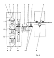
- FIG. 1 a device with a module 1 is shown, which has only a first chain magazine 1.1 and therefore does not fall under the claims.
- first chain magazine 1.1 workpieces W are stored with mutually parallel horizontal axes.
- the position of the workpieces W is by movement / rotation the chains of the chain magazine not separately designated changeable.
- the module 1 is adjoined by a feeder 2, which is displaceable horizontally in the X direction by means of a linear module 2.1 and extracts and forwards the tools in the Y direction.
- the feeder 2 has to gripper 2.2 for handling the tools W on.
- the feeder is followed by a transfer magazine 3, which is likewise designed as a chain magazine.
- a gripper 2.2 is arranged in the direction of the first chain magazine 1.1 and a gripper 2.2 in the direction of the transfer magazine 3.
- the transfer magazine 3 the workpieces W are stored, which are required for the direct processing of the respective workpiece (not shown).
- the tools W are replaced by a transfer station 4 in the work spindle 5 or replaced.
- the transfer station on gripper 4.2 In the area of the work spindle 5 is the working space A. E denotes the end positions of the tools W, which are taken when replacing.
- the module 1 and the feeder 2 are arranged together in a panel 6, in which also the cabinet S is integrated.
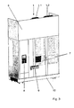
- FIG. 2 A similar device, but with a module 1, which has three chain magazines 1.1, 1.2, 1.3, is in FIG. 2 shown.
- the length of the feeder 2 is adapted to the length of the module 1. If a chain magazine 1.1, 1.2, 1.3 is loaded, this is locked for the feeder 2.
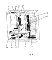
- the panel 6 has windows 7, which are automatically opened to load the workpieces.
- the windows 7 are arranged in a favorable ergonomic position for the operator.
- a control panel 8 is provided for inputting the tool data in the housing 6. These can also be read in via a reading device 9 also arranged on the lining 6.
- the module 1, the feeder 2, the control cabinet S and the panel 7 sit on a base frame 10th
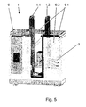
- FIG. 4 This structural unit from the direction of the feeder 2 is in FIG. 4 shown. From this view it can be seen that the cladding has horizontal struts 6.1 on its upper side. Between the horizontal overhead Struts 6.1 and the base frame 10 extend vertical struts 6.2 and from the horizontal struts 6.1 to the vertical struts 6.2 oblique support struts 6.3. The vertical struts 6.2 serve for fastening the first and second chain magazine 1.1, 1.2 of the module 1. Furthermore, the linear strut 6.2, which is seated on a carrier unit 2.4, is arranged with the feeder 2 on the vertical struts 6.2. To power the feeder 2 is an energy pipe 2.3.
- the device which consists essentially of module 1, feeder 2, transfer magazine 3, transfer station 4, according to special requirements can still be extended (not shown), for example by a tool cleaning device or a control station for detecting tool breakage and / or wear and / or to protect against replacement of wrong tools.
- the cleaning device is preferably arranged between the module and feeder.
- the control station is located before or after the transfer station or is in the Transfer station is integrated. In this case, for example, the tool breakage control takes place by detecting the difference in length of the tool to be replaced or replaced in comparison to the desired length of the respective workpiece.
- feeder 2 linear module 2.1 and gripper 2.2 as well as transfer station 4 and the corresponding grippers 4.2 is at the discretion of the expert and is determined by the type of tool holders and tool size.
Description
- Die Erfindung betrifft eine Vorrichtung zum Speichern und Handhaben von Werkzeugen eines Bearbeitungszentrums.
- Gemäß
JP 62 044336 A -
DE 699 02 974 T2 beschreibt eine Vorrichtung zum Speichern und Wechseln von Werkzeugen einer Werkzeugmaschine und ein Arbeitsverfahren dieser Vorrichtung. Diese Vorrichtung besteht aus einem Modul zur Werkzeuglagerung mit einer Vielzahl von zueinander fluchtenden Werkzeugaufnahmen, einem Handhabungsmodul, der sich in einer vertikalen Ebene bewegt und einem Übergabemodul zum Übergeben des Werkzeuges zur Aufnahme in einem z.B. Hochgeschwindigkeitsbearbeitungszentrum. Nachteilig dabei ist, dass nicht mehrere Werkzeuge zwischengespeichert werden können und dass ungenügende Kombinationsvarianten zur Aufnahme der Werkzeuge gegeben sind. Weiterhin sind durch die großen vertikalen Verfahrwege des Handhabungsmoduls hohe Werkzeugwechselzeiten zu verzeichnen. -
DE-4033036-A offenbart eine Vorrichtung nach dem Oberbegriff von Anspruch 1. - Aufgabe der Erfindung ist es, eine Vorrichtung zum Speichern von Werkzeugen eines Bearbeitungszentrums zu entwickeln, die ein zwischenspeichern mehrerer Werkzeuge gewährleistet und eine modulare Bauweise entsprechend der Anzahl der zu speichernden Werkzeuge ermöglicht, wobei eine große Einsatz- und Kombinationsmöglichkeit erzielbar ist.
- Diese Aufgabe wird mit den Merkmalen des ersten Patentanspruchs gelöst. Vorteilhafte Ausführungen ergeben sich aus den Unteransprüchen.
- Die Vorrichtung zum Speichern und Handhaben von Werkzeugen eines Bearbeitungszentrums weist ein Modul zur Werkzeuglagerung auf, welches eine Vielzahl von zueinander fluchtenden Werkzeugaufnahmen besitzt und eine entlang des Moduls verfahrbaren Zubringer, mit welchem Werkzeuge aus dem Modul entnehmbar und in das Modul einlegbar sind, wobei das dem Bearbeitungszentrum zugeordnete Modul zur Werkzeuglagerung aus einem oder mehreren nebeneinander angeordneten Kettenmagazinen besteht, und der in einer horizontalen Ebene entlang den Kettenmagazinen bewegbare Zubringer mit einem zur Zwischenspeicherung von Werkzeugen dienenden, ebenfalls als Kettenmagazin ausgebildeten Übergabemagazin zur Übergabe/Entnahme von Werkzeugen in Kontakt bringbar ist, und sich an das Übergabemagazin eine Übergabestation zur Übergabe/Entnahme von Werkzeugen zu/von der Arbeitsspindel anschließt.
- Das Modul weist zwei oder mehr nebeneinander angeordnete baugleiche Kettenmagazine auf. Die Kettenmagazine des Moduls sind mit einer Verkleidung versehen, die selbsttätig öffnenden Beschickungsfenster aufweist. Dabei ist bevorzugt jedem Kettenmagazin des Moduls ein Beschickungsfenster zugeordnet, wobei die Beschickungsfenster mehrerer Kettenmagazine in einer gleichen ergonomischen Höhe angeordnet sind.
- Das Modul weist weiterhin eine NC-Bedientafel zur Speicherung der Werkzeugdaten auf. Die Speicherung dieser Daten kann per Hand erfolgen oder mittels einer am Modul vorgesehenen Leseeinrichtung. Das Modul und das Übergabemagazin weisen mehrere Handlingplätze auf, z.B. 2 bis 10 Handlingsplätze. Im Übergabemagazin werden dabei die Werkzeuge gespeichert, die für die unmittelbaren Bearbeitungsvorgänge des Bearbeitungszentrums benötigt werden. Vorteilhafter Weise ist eine Reinigungsstation, z.B. Waschstation, zum Säubern der Werkzeuge vorgesehen, die vorzugsweise zwischen Modul zur Werkzeuglagerung und
- Zubringer angeordnet und beim Auswechseln und/oder Einwechseln der Werkzeuge aktivierbar ist. Weiterhin kann optional eine Kontrollstation zur Erkennung von werkzeugbruch und/oder -Verschleiß und/oder zum Schutz vor dem Einwechseln falscher Werkzeuge vorgesehen sein. Die Kontrollstation wird dabei bevorzugt vor oder nach der Übergabestation angeordnet oder in die Übergabestation integriert.
- Mit der Erfindung wird eine Vorrichtung zum Speichern und Handhaben von Werkzeugen eines Bearbeitungszentrums geschaffen, die durch ihre modulare Bauweise leicht den Erfordernissen des jeweiligen Bearbeitungszentrums angepasst werden kann. Je nach der Anzahl der bereitzustellenden Werkzeuge kann die Anzahl der im Modul integrierten Kettenmagazine variiert werden. Eine weitere Variantenvielfalt wird durch die Wahl von Kettenmagazinen mit entsprechenden Speicherplätzen geschaffen. So können z.B. Module mit 2 bis 4 Kettenmagazinen und jeweils 60 Speicherplätzen oder Module mit 2 bis 4 Kettenmagazinen und jeweils 80 Speicherplätzen je Kettenmagazin eingesetzt werden. Dazu kommen die Speicherplätze des Übergabemagazins (ebenfalls 60 oder 80), so dass in diesem Fall bis 320 Werkzeuge gespeichert werden können. Die Kettenmagazine ermöglichen die Bereitstellung des Werkzeuge an einer definierten Übergabeposition, so dass der Zubringer sich nur in einer horizontalen Ebene bewegen muss. Während der Zubringer ein Werkzeug an das Übergabemagazin weitergibt, kann durch ein Kettenmagazin des Moduls bereits das nächste Werkzeug in Übergabeposition bewegt werden. Jedes Magazin des Moduls ist direkt für den Bediener zugänglich, wobei die Beschickungsfenster in einer ergonomisch günstigen Höhe angeordnet sind und sich selbsttätig öffnen. Anstelle von Kettenmagazine können äquivalent auch Zahnriemenmagazine oder andere Magazine, die eine Bewegung der Werkstücke an die Übergabeposition zum Zubringer gewährleisten, eingesetzt werden.
- Mit dieser Erfindung verkürzen sich die Werkzeugbereitstellzeiten gegenüber bisherigen Lösungen ca. um 50%. Dies ist verbunden durch die hohe Funktionalität und Zuverlässigkeit durch den Einsatz bewehrter Kettenmagazine oder Zahnriemenmagazine. Weiterhin sind die Werkzeugkegel im Magazin vor Verschmutzung geschützt. Dadurch ist eine Kegelreinigung nicht zwingend erforderlich, kann jedoch optional vorgesehen werden.
- Die Erfindung wird nachfolgend anhand von Ausführungsbeispielen näher erläutert. Es zeigen:
- Fig. 1:
- Vorrichtung mit einem Modul 1, welcher ein erstes Kettenmagazin 1.1 aufweist. Diese Vorrichtung fällt nicht unter die Ansprüche.
- Fig. 2:
- Vorrichtung mit einem Modul 1, welcher drei Kettenmagazine 1.1, 1.2, 1.3 aufweist,
- Fig. 3:
- Modul 1, welcher ein erstes 1.1 und ein zweites Kettenmagazin 1.2 aufweist mit Verkleidung 6 in dreidimensionaler Ansicht aus Beschickungsrichtung,
- Fig. 4:
- Modul 1 gem.
Fig. 2 aus Richtung des Zubringers 2, - Fig. 5:
- Modul 1 mit teilweise entfernter Verkleidung 6.
- In
Figur 1 ist eine Vorrichtung mit einem Modul 1 dargestellt, welcher lediglich ein erstes Kettenmagazin 1.1 aufweist und daher nicht unter die Ansprüche fällt. In dem ersten Kettenmagazin 1.1 sind Werkstücke W mit zueinander parallelen horizontalen Achsen gespeichert. - Die Position der Werkstücke W ist durch Bewegung/Rotation der nicht separat bezeichneten Ketten des Kettenmagazins veränderbar. An den Modul 1 schließt sich ein Zubringer 2 an, welcher mittels eines Linearmoduls 2.1 horizontal in X-Richtung verschiebbar ist und in Y-Richtung die Werkzeuge entnimmt und weitergibt. Der Zubringer 2 weist dazu Greifer 2.2 zur Handhabung der Werkzeuge W auf.
- An den Zubringer schließt sich ein Übergabemagazin 3 an, welches ebenfalls als Kettenmagazin ausgebildet ist. Jeweils ein Greifer 2.2 ist in Richtung zum ersten Kettenmagazin 1.1 und ein Greifer 2.2 in Richtung zum Übergabemagazin 3 angeordnet. In dem Übergabemagazin 3 sind die Werkstücke W gespeichert, die für die unmittelbare Bearbeitung des jeweiligen Werkstückes (nicht dargestellt) erforderlich sind.
- Aus dem Übergabemagazin 3 werden die Werkzeuge W mittels einer Übergabestation 4 in die Arbeitsspindel 5 eingewechselt bzw. aus dieser ausgewechselt. Dazu weist die Übergabestation Greifer 4.2 auf. Im Bereich der Arbeitsspindel 5 befindet sich der Arbeitsraum A. Mit E sind die Endstellungen der Werkzeuge W bezeichnet, die beim Auswechseln eingenommen werden.
- Der Modul 1 und der Zubringer 2 sind gemeinsam in einer Verkleidung 6 angeordnet, in welche auch der Schaltschrank S integriert ist.
- Eine ähnliche Vorrichtung, jedoch mit einem Modul 1, welcher drei Kettenmagazine 1.1, 1.2, 1.3 aufweist, ist in
Figur 2 dargestellt. Die Länge des Zubringers 2 ist der Länge des Moduls 1 angepaßt. Wenn ein Kettenmagazin 1.1, 1.2, 1.3 beladen wird, ist dieses für die den Zubringer 2 gesperrt. - Ein Modul 1, welcher ein erstes 1.1 und ein zweites Kettenmagazin 1.2 aufweist, mit Verkleidung 6 in dreidimensionaler Ansicht aus Beschickungsrichtung, wird in
Figur 3 gezeigt. Die Verkleidung 6 besitzt Fenster 7, welche sich automatisch zum Beschicken der Werkstücke geöffnet werden. Die Fenster 7 sind dabei in einer für den Bediener günstigen ergonomischen Position angeordnet. Von der Verkleidung 6 werden der Modul 1 (erstes und zweites Kettenmagazin 1.1, 1.2) und der Zubringer 2 umhaust. In Bedienrichtung ist im Gehäuse 6 eine Bedientafel 8 zur Eingabe der Werkzeugdaten vorgesehen. Diese können auch über eine ebenfalls an der Verkleidung 6 angeordnete Leseeinrichtung 9 eingelesen werden. Das Modul 1, der Zubringer 2, der Schaltschrank S und die Verkleidung 7 sitzen auf einem Grundgestell 10. - Diese bauliche Einheit aus Richtung des Zubringers 2 wird in
Figur 4 dargestellt. Aus dieser Ansicht ist ersichtlich, dass die Verkleidung an ihrer Oberseite horizontale Streben 6.1 aufweist. Zwischen den oben liegenden horizontalen Streben 6.1 und dem Grundgestell 10 erstrecken sich vertikale Streben 6.2 und von den horizontalen Streben 6.1 zu den vertikalen Streben 6.2 schräge Stützstreben 6.3. Die vertikalen Streben 6.2 dienen zur Befestigung des ersten und zweiten Kettenmagazins 1.1, 1.2 des Moduls 1. Weiterhin ist an den vertikalen Streben 6.2 der auf einer Trägereinheit 2.4 sitzende Linearmodul 2.1 mit dem Zubringer 2 angeordnet. Zur Stromversorgung des Zubringers 2 dient ein Energierohr 2.3. - Einen Modul 1 mit teilweise entfernter Verkleidung 6. Ist in Figur 6 dargestellt. Es wurde der Mittelbereich der vertikalen Streben demontiert und der Mittelbereich der Verkleidung entfernt. Dadurch kann das entsprechende Kettenmagazin (hier 1.1) von vorn montiert oder demontiert werden.
- Die Vorrichtung, die im wesentlichen aus Modul 1, Zubringer 2, Übergabemagazin 3, Übergabestation 4 besteht, kann entsprechend spezieller Anforderungen noch erweitert werden (nicht dargestellt), z.B. durch eine Werkzeugreinigungsvorrichtung oder einer Kontrollstation zur Erkennung von Werkzeugbruch und/oder -Verschleiß und/oder zum Schutz vor dem Einwechseln falscher Werkzeugen. Die Reinigungsvorrichtung ist dabei bevorzugt zwischen Modul und Zubringer angeordnet. Die Kontrollstation befindet sich vor oder nach der Übergabestation oder ist in die Übergabestation integriert ist. Dabei erfolgt z.B. die Werkzeugbruchkontrolle durch Erfassen der Längendifferenz des ein- oder auszuwechselnden Werkzeuges im Vergleich zur Soll-Länge des jeweiligen Werkstücks.
- Neben den beschriebenen Ausführungsbeispielen ist es auch möglich, entsprechende Vorrichtungen zu verwenden, die Module mit vier oder mehr Kettenmagazinen aufweisen.
- Die konstruktive Gestaltung und Auslegung von Zubringer 2, Linearmodul 2.1 und Greifer 2.2 sowie von Übergabestation 4 und den entsprechenden Greifern 4.2 liegt im Ermessen des Fachmanns und wird bestimmt von der Art der Werkzeugaufnahmen und der Werkzeuggröße.
Claims (3)
- Vorrichtung zum Speichern und Handhaben von Werkzeugen eines Bearbeitungszentrums, mit einem Modul (1) zur Werkzeuglagerung, welches eine Vielzahl von zueinander fluchtenden Werkzeugaufnahmen aufweist und einem entlang dem Modul (1) verfahrbaren Zubringer (2), mit welchem Werkzeuge (W) aus dem Modul (1) entnehmbar und in das Modul (1) einlegbar sind, wobei sich an den Zubringer ein zur zwischenspeicherung von Werkzeugen dienendes als Kettenmagazin ausgebildetes Übergabemagazin (3) und an das Übergabemagazin (3) eine Übergabestation (4) zur Übergabe/Entnahme von Werkzeugen (W) zu/von der Arbeitsspindel (5) anschließt,
dadurch gekennzeichnet,- dass das Modul (1) aus wenigstens zwei nebeneinander angeordneten baugleichen Kettenmagazinen (1.1) besteht,- dass der Zubringer (2) nur in einer horizontalen Ebene entlang dem Modul (1) bewegbar ist,- dass das Modul (1) und der Zubringer (2) als bauliche Einheit ausgebildet und auf einem gemeinsamen Grundgestell (10) angeordnet sind. - Vorrichtung nach Anspruch 1, dadurch gekennzeichnet, dass das Modul (1) 2 bis 10 Handlingsplätze aufweist.
- Vorrichtung nach Anspruch 1 oder 2, dadurch gekennzeichnet, dass das Übergabemagazin (3) 2 bis 10 Handlingsplätze aufweist.
Applications Claiming Priority (2)
| Application Number | Priority Date | Filing Date | Title |
|---|---|---|---|
| DE202004009642U DE202004009642U1 (de) | 2004-06-14 | 2004-06-14 | Vorrichtung zum Speichern und Handhaben von Werkzeugen eines Bearbeitungszentrums |
| PCT/DE2005/001078 WO2005120768A2 (de) | 2004-06-14 | 2005-06-14 | Vorrichtung zum speichern und handhaben von werkzeugen eines bearbeitungszentrums |
Publications (2)
| Publication Number | Publication Date |
|---|---|
| EP1755823A2 EP1755823A2 (de) | 2007-02-28 |
| EP1755823B1 true EP1755823B1 (de) | 2009-11-18 |
Family
ID=35005667
Family Applications (1)
| Application Number | Title | Priority Date | Filing Date |
|---|---|---|---|
| EP05763269A Active EP1755823B1 (de) | 2004-06-14 | 2005-06-14 | Vorrichtung zum speichern und handhaben von werkzeugen eines bearbeitungszentrums |
Country Status (4)
| Country | Link |
|---|---|
| EP (1) | EP1755823B1 (de) |
| AT (1) | ATE448904T1 (de) |
| DE (2) | DE202004009642U1 (de) |
| WO (1) | WO2005120768A2 (de) |
Cited By (1)
| Publication number | Priority date | Publication date | Assignee | Title |
|---|---|---|---|---|
| DE102020111330A1 (de) | 2020-04-27 | 2021-10-28 | Gebr. Heller Maschinenfabrik Gmbh | Werkzeugwechselvorrichtung für eine Werkzeugmaschine |
Families Citing this family (1)
| Publication number | Priority date | Publication date | Assignee | Title |
|---|---|---|---|---|
| JP6793099B2 (ja) * | 2017-09-04 | 2020-12-02 | Dmg森精機株式会社 | 搬送装置 |
Family Cites Families (7)
| Publication number | Priority date | Publication date | Assignee | Title |
|---|---|---|---|---|
| JPS56157934A (en) * | 1980-05-07 | 1981-12-05 | Mitsubishi Heavy Ind Ltd | Automatic tool exchanging type machine tool |
| DD215269A1 (de) * | 1983-06-10 | 1984-11-07 | Werkzeugmasch Forschzent | Vorrichtung zur speicherung kompletter werkzeugmagazine an automatischen werkzeugmaschinen |
| JPS6244336A (ja) * | 1985-08-23 | 1987-02-26 | Yasunaga Tekkosho:Kk | 自動工具交換装置 |
| DD258580A1 (de) * | 1986-05-07 | 1988-07-27 | Werkzeugmaschinenbau Fz | Werkzeug-zwischenspeicher fuer automatisch wechselbare werkzeuge im werkzeugwechselsystem einer nc-werkzeugmaschine |
| DE4033036A1 (de) * | 1990-07-03 | 1992-01-09 | Klessmann Ima Norte Maschfab | Werkzeugmaschine mit einem hintergrundmagazin |
| FR2780909B1 (fr) * | 1998-07-09 | 2000-10-06 | Renault Automation | Dispositif d'emmagasinage et de changement d'outils d'une machine-outil d'usinage et procede de travail d'un tel dispositif |
| DE10163294B4 (de) * | 2001-12-21 | 2010-09-09 | Deckel Maho Geretsried Gmbh | Werkzeugwechselsystem für programmgesteuerte Fräs- und Bohrmaschinen |
-
2004
- 2004-06-14 DE DE202004009642U patent/DE202004009642U1/de not_active Expired - Lifetime
-
2005
- 2005-06-14 WO PCT/DE2005/001078 patent/WO2005120768A2/de active Application Filing
- 2005-06-14 DE DE502005008546T patent/DE502005008546D1/de active Active
- 2005-06-14 EP EP05763269A patent/EP1755823B1/de active Active
- 2005-06-14 AT AT05763269T patent/ATE448904T1/de active
Cited By (1)
| Publication number | Priority date | Publication date | Assignee | Title |
|---|---|---|---|---|
| DE102020111330A1 (de) | 2020-04-27 | 2021-10-28 | Gebr. Heller Maschinenfabrik Gmbh | Werkzeugwechselvorrichtung für eine Werkzeugmaschine |
Also Published As
| Publication number | Publication date |
|---|---|
| DE502005008546D1 (de) | 2009-12-31 |
| ATE448904T1 (de) | 2009-12-15 |
| WO2005120768A3 (de) | 2006-05-11 |
| WO2005120768A2 (de) | 2005-12-22 |
| DE202004009642U1 (de) | 2005-10-27 |
| EP1755823A2 (de) | 2007-02-28 |
Similar Documents
| Publication | Publication Date | Title |
|---|---|---|
| DE19860492B4 (de) | Programmgesteuerte Fräs- und Bohrmaschine | |
| DE2739534C2 (de) | Werkzeugwechselvorrichtung | |
| DE3519706C2 (de) | ||
| DE102007018368B4 (de) | Werkzeugmaschinenanordnung mit automatischem Werkstück- und Werkzeugwechsel | |
| DE102004050035A1 (de) | Werkzeugmaschine und Verfahren zum Werkzeugwechsel an einer Werkzeugmaschine | |
| EP2310166B1 (de) | Werkzeugmaschine | |
| EP2060359A2 (de) | Schleifmaschine | |
| EP0885686A1 (de) | Bearbeitungszelle | |
| EP1616661A1 (de) | Werkstückwechsler für Bearbeitungsmaschinen | |
| DE102011053455A1 (de) | Werkzeugmaschine und Verfahren zum Austausch von Werkzeugen an einer Werkzeugmaschine | |
| DE60219267T2 (de) | Greifeinheit für die automatisierte Bearbeitung von Werkstücken, und Vorrichtung und Verfahren mit einer solchen Einheit | |
| EP3208034B1 (de) | Werkzeugmagazin | |
| EP0824389B1 (de) | Einrichtung zum funkenerosiven bearbeiten von werkstücken | |
| EP1755823B1 (de) | Vorrichtung zum speichern und handhaben von werkzeugen eines bearbeitungszentrums | |
| DE102005016510A1 (de) | Vorrichtung zum spanabhebenden Bearbeiten von gehärteten Werkstücken | |
| DE202014009762U1 (de) | Werkzeugwechselvorrichtung zur Verwendung in einem Bearbeitungszentrum und Bearbeitungszentrum zur maschinellen Bearbeitung eines Werkstücks | |
| DE69729850T2 (de) | Werkzeugmaschine mit einem Werkzeugmagazin mit erhöhter Kapazität und Werkzeugmagazin zum Ausrüsten einer Werkzeugmaschine | |
| DE102007042638B4 (de) | Beschickungs- und Entnahme-Anlage für Werkzeug-Maschinen | |
| EP1621284A1 (de) | Werkstückwechsler für Bearbeitungsmaschinen | |
| AT507328B1 (de) | Werkzeugmaschine | |
| DE102018104199B4 (de) | Werkzeugmaschine mit Arbeitsraum, Rüstplatz und Roboterarm und Verfahren zu deren Betrieb | |
| DE10336156B4 (de) | Bearbeitungsmaschine | |
| EP0417550B1 (de) | Werkzeugmaschine mit automatischem Wechsel autonom angetriebener Werkzeugmagazine | |
| DE10336159B4 (de) | Einrichtung zum Zuführen und Abführen von Werkstücken zu- bzw. von wenigstens einer Bearbeitungsmaschine | |
| DE10354706C5 (de) | Werkzeugmaschine mit Transportvorrichtung |
Legal Events
| Date | Code | Title | Description |
|---|---|---|---|
| PUAI | Public reference made under article 153(3) epc to a published international application that has entered the european phase |
Free format text: ORIGINAL CODE: 0009012 |
|
| 17P | Request for examination filed |
Effective date: 20061212 |
|
| AK | Designated contracting states |
Kind code of ref document: A2 Designated state(s): AT BE BG CH CY CZ DE DK EE ES FI FR GB GR HU IE IS IT LI LT LU MC NL PL PT RO SE SI SK TR |
|
| RIN1 | Information on inventor provided before grant (corrected) |
Inventor name: SCHOPPE, EBERHARD Inventor name: SCHWARZENBERGER, RAINER Inventor name: ZIEGLER, ANDREAS Inventor name: NEUBER, DIETER Inventor name: KEILING, ULF Inventor name: BELZ, HOLGER Inventor name: REH, JUERGEN Inventor name: WEIRAUCH, FRANK Inventor name: KEMTER, HEINO Inventor name: SEYFERT, SOEREN Inventor name: BECHER, MIRKO |
|
| RIN1 | Information on inventor provided before grant (corrected) |
Inventor name: BECHER, MIRKO Inventor name: SCHOPPE, EBERHARD Inventor name: WEIRAUCH, FRANK Inventor name: REH, JUERGEN Inventor name: SEYFERT, SOEREN Inventor name: KEILING, ULF Inventor name: NEUBER, DIETER Inventor name: SCHWARZENBERGER, RAINER Inventor name: BELZ, HOLGER Inventor name: ZIEGLER, ANDREAS Inventor name: KEMTER, HEINO |
|
| DAX | Request for extension of the european patent (deleted) | ||
| 17Q | First examination report despatched |
Effective date: 20080114 |
|
| GRAP | Despatch of communication of intention to grant a patent |
Free format text: ORIGINAL CODE: EPIDOSNIGR1 |
|
| GRAS | Grant fee paid |
Free format text: ORIGINAL CODE: EPIDOSNIGR3 |
|
| GRAA | (expected) grant |
Free format text: ORIGINAL CODE: 0009210 |
|
| AK | Designated contracting states |
Kind code of ref document: B1 Designated state(s): AT BE BG CH CY CZ DE DK EE ES FI FR GB GR HU IE IS IT LI LT LU MC NL PL PT RO SE SI SK TR |
|
| REG | Reference to a national code |
Ref country code: GB Ref legal event code: FG4D Free format text: NOT ENGLISH |
|
| REG | Reference to a national code |
Ref country code: CH Ref legal event code: EP |
|
| REG | Reference to a national code |
Ref country code: IE Ref legal event code: FG4D |
|
| REF | Corresponds to: |
Ref document number: 502005008546 Country of ref document: DE Date of ref document: 20091231 Kind code of ref document: P |
|
| REG | Reference to a national code |
Ref country code: NL Ref legal event code: VDEP Effective date: 20091118 |
|
| LTIE | Lt: invalidation of european patent or patent extension |
Effective date: 20091118 |
|
| PG25 | Lapsed in a contracting state [announced via postgrant information from national office to epo] |
Ref country code: SE Free format text: LAPSE BECAUSE OF FAILURE TO SUBMIT A TRANSLATION OF THE DESCRIPTION OR TO PAY THE FEE WITHIN THE PRESCRIBED TIME-LIMIT Effective date: 20091118 Ref country code: PT Free format text: LAPSE BECAUSE OF FAILURE TO SUBMIT A TRANSLATION OF THE DESCRIPTION OR TO PAY THE FEE WITHIN THE PRESCRIBED TIME-LIMIT Effective date: 20100318 Ref country code: ES Free format text: LAPSE BECAUSE OF FAILURE TO SUBMIT A TRANSLATION OF THE DESCRIPTION OR TO PAY THE FEE WITHIN THE PRESCRIBED TIME-LIMIT Effective date: 20100228 Ref country code: LT Free format text: LAPSE BECAUSE OF FAILURE TO SUBMIT A TRANSLATION OF THE DESCRIPTION OR TO PAY THE FEE WITHIN THE PRESCRIBED TIME-LIMIT Effective date: 20091118 Ref country code: FI Free format text: LAPSE BECAUSE OF FAILURE TO SUBMIT A TRANSLATION OF THE DESCRIPTION OR TO PAY THE FEE WITHIN THE PRESCRIBED TIME-LIMIT Effective date: 20091118 Ref country code: IS Free format text: LAPSE BECAUSE OF FAILURE TO SUBMIT A TRANSLATION OF THE DESCRIPTION OR TO PAY THE FEE WITHIN THE PRESCRIBED TIME-LIMIT Effective date: 20100318 |
|
| PG25 | Lapsed in a contracting state [announced via postgrant information from national office to epo] |
Ref country code: SI Free format text: LAPSE BECAUSE OF FAILURE TO SUBMIT A TRANSLATION OF THE DESCRIPTION OR TO PAY THE FEE WITHIN THE PRESCRIBED TIME-LIMIT Effective date: 20091118 Ref country code: CY Free format text: LAPSE BECAUSE OF FAILURE TO SUBMIT A TRANSLATION OF THE DESCRIPTION OR TO PAY THE FEE WITHIN THE PRESCRIBED TIME-LIMIT Effective date: 20091118 Ref country code: PL Free format text: LAPSE BECAUSE OF FAILURE TO SUBMIT A TRANSLATION OF THE DESCRIPTION OR TO PAY THE FEE WITHIN THE PRESCRIBED TIME-LIMIT Effective date: 20091118 |
|
| REG | Reference to a national code |
Ref country code: IE Ref legal event code: FD4D |
|
| PG25 | Lapsed in a contracting state [announced via postgrant information from national office to epo] |
Ref country code: NL Free format text: LAPSE BECAUSE OF FAILURE TO SUBMIT A TRANSLATION OF THE DESCRIPTION OR TO PAY THE FEE WITHIN THE PRESCRIBED TIME-LIMIT Effective date: 20091118 Ref country code: BG Free format text: LAPSE BECAUSE OF FAILURE TO SUBMIT A TRANSLATION OF THE DESCRIPTION OR TO PAY THE FEE WITHIN THE PRESCRIBED TIME-LIMIT Effective date: 20100218 Ref country code: DK Free format text: LAPSE BECAUSE OF FAILURE TO SUBMIT A TRANSLATION OF THE DESCRIPTION OR TO PAY THE FEE WITHIN THE PRESCRIBED TIME-LIMIT Effective date: 20091118 Ref country code: EE Free format text: LAPSE BECAUSE OF FAILURE TO SUBMIT A TRANSLATION OF THE DESCRIPTION OR TO PAY THE FEE WITHIN THE PRESCRIBED TIME-LIMIT Effective date: 20091118 Ref country code: RO Free format text: LAPSE BECAUSE OF FAILURE TO SUBMIT A TRANSLATION OF THE DESCRIPTION OR TO PAY THE FEE WITHIN THE PRESCRIBED TIME-LIMIT Effective date: 20091118 Ref country code: IE Free format text: LAPSE BECAUSE OF FAILURE TO SUBMIT A TRANSLATION OF THE DESCRIPTION OR TO PAY THE FEE WITHIN THE PRESCRIBED TIME-LIMIT Effective date: 20091118 |
|
| PG25 | Lapsed in a contracting state [announced via postgrant information from national office to epo] |
Ref country code: SK Free format text: LAPSE BECAUSE OF FAILURE TO SUBMIT A TRANSLATION OF THE DESCRIPTION OR TO PAY THE FEE WITHIN THE PRESCRIBED TIME-LIMIT Effective date: 20091118 Ref country code: CZ Free format text: LAPSE BECAUSE OF FAILURE TO SUBMIT A TRANSLATION OF THE DESCRIPTION OR TO PAY THE FEE WITHIN THE PRESCRIBED TIME-LIMIT Effective date: 20091118 |
|
| PLBE | No opposition filed within time limit |
Free format text: ORIGINAL CODE: 0009261 |
|
| STAA | Information on the status of an ep patent application or granted ep patent |
Free format text: STATUS: NO OPPOSITION FILED WITHIN TIME LIMIT |
|
| 26N | No opposition filed |
Effective date: 20100819 |
|
| PG25 | Lapsed in a contracting state [announced via postgrant information from national office to epo] |
Ref country code: GR Free format text: LAPSE BECAUSE OF FAILURE TO SUBMIT A TRANSLATION OF THE DESCRIPTION OR TO PAY THE FEE WITHIN THE PRESCRIBED TIME-LIMIT Effective date: 20100219 |
|
| BERE | Be: lapsed |
Owner name: STARRAGHECKERT G.M.B.H. Effective date: 20100630 |
|
| PG25 | Lapsed in a contracting state [announced via postgrant information from national office to epo] |
Ref country code: MC Free format text: LAPSE BECAUSE OF NON-PAYMENT OF DUE FEES Effective date: 20100630 |
|
| GBPC | Gb: european patent ceased through non-payment of renewal fee |
Effective date: 20100614 |
|
| PG25 | Lapsed in a contracting state [announced via postgrant information from national office to epo] |
Ref country code: BE Free format text: LAPSE BECAUSE OF NON-PAYMENT OF DUE FEES Effective date: 20100630 |
|
| PG25 | Lapsed in a contracting state [announced via postgrant information from national office to epo] |
Ref country code: GB Free format text: LAPSE BECAUSE OF NON-PAYMENT OF DUE FEES Effective date: 20100614 |
|
| REG | Reference to a national code |
Ref country code: DE Ref legal event code: R082 Ref document number: 502005008546 Country of ref document: DE Representative=s name: GABRIELE RUMRICH, DE |
|
| PG25 | Lapsed in a contracting state [announced via postgrant information from national office to epo] |
Ref country code: LU Free format text: LAPSE BECAUSE OF NON-PAYMENT OF DUE FEES Effective date: 20100614 Ref country code: HU Free format text: LAPSE BECAUSE OF FAILURE TO SUBMIT A TRANSLATION OF THE DESCRIPTION OR TO PAY THE FEE WITHIN THE PRESCRIBED TIME-LIMIT Effective date: 20100519 |
|
| PG25 | Lapsed in a contracting state [announced via postgrant information from national office to epo] |
Ref country code: TR Free format text: LAPSE BECAUSE OF FAILURE TO SUBMIT A TRANSLATION OF THE DESCRIPTION OR TO PAY THE FEE WITHIN THE PRESCRIBED TIME-LIMIT Effective date: 20091118 |
|
| REG | Reference to a national code |
Ref country code: DE Ref legal event code: R081 Ref document number: 502005008546 Country of ref document: DE Owner name: HECKERT GMBH, DE Free format text: FORMER OWNER: STARRAGHECKERT GMBH, 09117 CHEMNITZ, DE Effective date: 20120921 Ref country code: DE Ref legal event code: R082 Ref document number: 502005008546 Country of ref document: DE Representative=s name: GABRIELE RUMRICH, DE Effective date: 20120921 Ref country code: DE Ref legal event code: R081 Ref document number: 502005008546 Country of ref document: DE Owner name: STARRAG GMBH, DE Free format text: FORMER OWNER: STARRAGHECKERT GMBH, 09117 CHEMNITZ, DE Effective date: 20120921 Ref country code: DE Ref legal event code: R082 Ref document number: 502005008546 Country of ref document: DE Representative=s name: RUMRICH, GABRIELE, DIPL.-ING. PAT.-ING., DE Effective date: 20120921 |
|
| REG | Reference to a national code |
Ref country code: AT Ref legal event code: HC Ref document number: 448904 Country of ref document: AT Kind code of ref document: T Owner name: HECKERT GMBH, DE Effective date: 20130506 |
|
| REG | Reference to a national code |
Ref country code: FR Ref legal event code: PLFP Year of fee payment: 11 |
|
| REG | Reference to a national code |
Ref country code: CH Ref legal event code: PFA Owner name: HECKERT GMBH, DE Free format text: FORMER OWNER: STARRAGHECKERT GMBH, DE |
|
| PGFP | Annual fee paid to national office [announced via postgrant information from national office to epo] |
Ref country code: FR Payment date: 20150623 Year of fee payment: 11 |
|
| REG | Reference to a national code |
Ref country code: FR Ref legal event code: CD Owner name: HECKERT GMBH, DE Effective date: 20151012 |
|
| REG | Reference to a national code |
Ref country code: FR Ref legal event code: ST Effective date: 20170228 |
|
| PG25 | Lapsed in a contracting state [announced via postgrant information from national office to epo] |
Ref country code: FR Free format text: LAPSE BECAUSE OF NON-PAYMENT OF DUE FEES Effective date: 20160630 |
|
| REG | Reference to a national code |
Ref country code: DE Ref legal event code: R082 Ref document number: 502005008546 Country of ref document: DE Representative=s name: RUMRICH, GABRIELE, DIPL.-ING. PAT.-ING., DE Ref country code: DE Ref legal event code: R081 Ref document number: 502005008546 Country of ref document: DE Owner name: STARRAG GMBH, DE Free format text: FORMER OWNER: HECKERT GMBH, 09117 CHEMNITZ, DE |
|
| REG | Reference to a national code |
Ref country code: CH Ref legal event code: PFA Owner name: STARRAG GMBH, DE Free format text: FORMER OWNER: HECKERT GMBH, DE |
|
| REG | Reference to a national code |
Ref country code: AT Ref legal event code: HC Ref document number: 448904 Country of ref document: AT Kind code of ref document: T Owner name: STARRAG GMBH, DE Effective date: 20171220 |
|
| PGFP | Annual fee paid to national office [announced via postgrant information from national office to epo] |
Ref country code: AT Payment date: 20220617 Year of fee payment: 18 |
|
| PGFP | Annual fee paid to national office [announced via postgrant information from national office to epo] |
Ref country code: IT Payment date: 20220630 Year of fee payment: 18 |
|
| PGFP | Annual fee paid to national office [announced via postgrant information from national office to epo] |
Ref country code: CH Payment date: 20220629 Year of fee payment: 18 |
|
| PGFP | Annual fee paid to national office [announced via postgrant information from national office to epo] |
Ref country code: DE Payment date: 20230606 Year of fee payment: 19 |
|
| REG | Reference to a national code |
Ref country code: CH Ref legal event code: PL |
|
| REG | Reference to a national code |
Ref country code: AT Ref legal event code: MM01 Ref document number: 448904 Country of ref document: AT Kind code of ref document: T Effective date: 20230614 |