EP1755434B1 - Tablet dispenser with isolated product hopper - Google Patents
Tablet dispenser with isolated product hopper Download PDFInfo
- Publication number
- EP1755434B1 EP1755434B1 EP05730773A EP05730773A EP1755434B1 EP 1755434 B1 EP1755434 B1 EP 1755434B1 EP 05730773 A EP05730773 A EP 05730773A EP 05730773 A EP05730773 A EP 05730773A EP 1755434 B1 EP1755434 B1 EP 1755434B1
- Authority
- EP
- European Patent Office
- Prior art keywords
- aperture
- disk member
- dispenser
- product tablets
- diameter
- Prior art date
- Legal status (The legal status is an assumption and is not a legal conclusion. Google has not performed a legal analysis and makes no representation as to the accuracy of the status listed.)
- Expired - Lifetime
Links
- 238000007789 sealing Methods 0.000 claims description 3
- 239000000047 product Substances 0.000 description 112
- 238000004851 dishwashing Methods 0.000 description 24
- 230000007246 mechanism Effects 0.000 description 16
- 239000000126 substance Substances 0.000 description 8
- 230000007613 environmental effect Effects 0.000 description 4
- 230000003287 optical effect Effects 0.000 description 3
- 238000005282 brightening Methods 0.000 description 2
- 238000009833 condensation Methods 0.000 description 2
- 230000005494 condensation Effects 0.000 description 2
- 239000000356 contaminant Substances 0.000 description 2
- 239000003599 detergent Substances 0.000 description 2
- 239000002979 fabric softener Substances 0.000 description 2
- 239000012530 fluid Substances 0.000 description 2
- 239000000203 mixture Substances 0.000 description 2
- 239000008188 pellet Substances 0.000 description 2
- 230000004044 response Effects 0.000 description 2
- 238000011012 sanitization Methods 0.000 description 2
- 238000009955 starching Methods 0.000 description 2
- 230000003068 static effect Effects 0.000 description 2
- 230000009471 action Effects 0.000 description 1
- 230000004888 barrier function Effects 0.000 description 1
- 230000005540 biological transmission Effects 0.000 description 1
- 239000003518 caustics Substances 0.000 description 1
- 238000004140 cleaning Methods 0.000 description 1
- 230000008878 coupling Effects 0.000 description 1
- 238000010168 coupling process Methods 0.000 description 1
- 238000005859 coupling reaction Methods 0.000 description 1
- 238000001704 evaporation Methods 0.000 description 1
- 230000008020 evaporation Effects 0.000 description 1
- 239000006052 feed supplement Substances 0.000 description 1
- 239000008187 granular material Substances 0.000 description 1
- 238000002955 isolation Methods 0.000 description 1
- 238000004519 manufacturing process Methods 0.000 description 1
- 239000002245 particle Substances 0.000 description 1
- 239000000843 powder Substances 0.000 description 1
- -1 rinse aids Substances 0.000 description 1
- 230000035945 sensitivity Effects 0.000 description 1
- 238000000926 separation method Methods 0.000 description 1
- 239000012265 solid product Substances 0.000 description 1
- 239000007921 spray Substances 0.000 description 1
- 239000003826 tablet Substances 0.000 description 1
Images


Classifications
-
- A—HUMAN NECESSITIES
- A47—FURNITURE; DOMESTIC ARTICLES OR APPLIANCES; COFFEE MILLS; SPICE MILLS; SUCTION CLEANERS IN GENERAL
- A47L—DOMESTIC WASHING OR CLEANING; SUCTION CLEANERS IN GENERAL
- A47L15/00—Washing or rinsing machines for crockery or tableware
- A47L15/42—Details
- A47L15/44—Devices for adding cleaning agents; Devices for dispensing cleaning agents, rinsing aids or deodorants
- A47L15/4409—Devices for adding cleaning agents; Devices for dispensing cleaning agents, rinsing aids or deodorants by tipping containers or opening their lids, e.g. with the help of a programmer
-
- A—HUMAN NECESSITIES
- A47—FURNITURE; DOMESTIC ARTICLES OR APPLIANCES; COFFEE MILLS; SPICE MILLS; SUCTION CLEANERS IN GENERAL
- A47L—DOMESTIC WASHING OR CLEANING; SUCTION CLEANERS IN GENERAL
- A47L15/00—Washing or rinsing machines for crockery or tableware
- A47L15/42—Details
- A47L15/44—Devices for adding cleaning agents; Devices for dispensing cleaning agents, rinsing aids or deodorants
- A47L15/4463—Multi-dose dispensing arrangements
-
- B—PERFORMING OPERATIONS; TRANSPORTING
- B01—PHYSICAL OR CHEMICAL PROCESSES OR APPARATUS IN GENERAL
- B01F—MIXING, e.g. DISSOLVING, EMULSIFYING OR DISPERSING
- B01F21/00—Dissolving
- B01F21/20—Dissolving using flow mixing
-
- B—PERFORMING OPERATIONS; TRANSPORTING
- B01—PHYSICAL OR CHEMICAL PROCESSES OR APPARATUS IN GENERAL
- B01F—MIXING, e.g. DISSOLVING, EMULSIFYING OR DISPERSING
- B01F35/00—Accessories for mixers; Auxiliary operations or auxiliary devices; Parts or details of general application
- B01F35/71—Feed mechanisms
- B01F35/714—Feed mechanisms for feeding predetermined amounts
- B01F35/7141—Feed mechanisms for feeding predetermined amounts using measuring chambers moving between a loading and unloading position, e.g. reciprocating feed frames
- B01F35/71411—Feed mechanisms for feeding predetermined amounts using measuring chambers moving between a loading and unloading position, e.g. reciprocating feed frames rotating or oscillating about an axis
- B01F35/714112—Feed mechanisms for feeding predetermined amounts using measuring chambers moving between a loading and unloading position, e.g. reciprocating feed frames rotating or oscillating about an axis the measuring chambers being channels extending between both front faces of a rotating cylinder or disc
Definitions
- the present invention relates to a product tablet dispenser with an isolated product hopper containing a plurality of product tablets.
- Solid product compositions in tablet form are typically used because they are relatively easy to formulate and dispense in a desired dosage.
- Such product tablets may be used for a variety of products including detergents, sanitizers, rinse aids, fabric softeners, bleaches, optical brightening chemicals, starching chemicals, and cleaners and sanitizers in general.
- the product tablets may be caustic, messy, or otherwise difficult to handle and/or susceptible to environmental conditions such as humidity or other chemicals that can cause the product to clump or dissolve and disrupt the dispensing of the product.
- Dispensers are typically used to dispense product tablets.
- the use of dispensers reduces the handling of the product tablets and allows for easy dispensing of the product in the desired dosage.
- the prior art dispensers are typically not effective in reducing exposure of the product tablets to the environmental conditions in which the product tablets are dispensed. As a result of being exposed to the environmental conditions, the product tablets may clump or dissolve thereby clogging the dispenser. If the dispenser becomes clogged, the dispenser will not dispense the product tablets properly.
- Prior art dispensers also include outlets with various types of sensors.
- One type of outlet that has been used includes a tube with two small holes on opposite sides of the tube, and a beam of light is emitted and received through the holes in the tube.
- the product tablet momentarily interrupts the reception of the beam of light, and the sensor provides a signal pulse indicating that the product tablet has been dispensed.
- a drawback to this configuration is that it can result in blockage of the holes through which the beam of light passes thereby disabling the operation of the sensor.
- the holes could be blocked by powder or small particles of the product tablets being dispensed, condensation, residual product, and other residue such as from evaporation of chemical laden moisture from the dishwashing machine.
- US 2,664,223 describes a can with a buit-in dispenser for dispensing pellets.
- a preferred embodiment dispenser for dispensing product tablets includes a first disk member, a second disk member, and a third disk member.
- the first disk member includes a first aperture extending longitudinally through the first disk member, and the first disk member is rotatable.
- the second disk member includes a second aperture extending longitudinally through the second disk member, and the second disk member is stationary.
- the first aperture is intermittently aligned with the second aperture.
- the third disk member includes a third aperture extending longitudinally through the third disk member, and the third disk member is rotatable.
- the third disk member is intermittently aligned with the second aperture.
- the third aperture and the first aperture are positioned at different locations with respect to the second aperture thereby aligning with the second aperture at separate times resulting in an interrupted flow path for the product tablets.
- a preferred embodiment tablet dispenser includes a hopper and an interrupted flow path.
- the hopper has a cavity configured and arranged to contain a plurality of product tablets.
- the interrupted flow path is in fluid communication with the cavity of the hopper.
- the flow path includes a first disk member having a first aperture, a second disk member having a second aperture, and a third disk member having a third aperture.
- a predetermined quantity of product tablets enter the first aperture, the first disk member is rotated to align the first aperture and the second aperture, the predetermined quantity of product tablets flow from the first aperture into the second aperture, the third disk member is rotated to align the second aperture and the third aperture, the predetermined quantity of product tablets flow from the second aperture into the third aperture, and the predetermined quantity of product tablets are dispensed.
- the flow path is sealed by the disk members to prevent exposure of the plurality of product tablets contained within the hopper to outside elements.
- a preferred embodiment dispenser for dispensing product tablets includes a hopper, a first disk member, a second disk member, a third disk member, a motor, and a flow path.
- the hopper has a cavity and a bottom.
- the cavity is configured and arranged to contain the product tablets, and the bottom includes an opening providing access to the cavity.
- the first disk member is configured and arranged to fit within the cavity proximate the opening of the hopper.
- the first disk member includes a first aperture extending longitudinally through the first disk member.
- the second disk member, to which the bottom of the hopper is operatively connected, is stationary and includes a bore and a second aperture. The bore extends longitudinally through the second disk member proximate a center portion of the second disk member.
- the second aperture extends longitudinally through the second disk member and is intermittently aligned with the first aperture.
- the third disk member includes a boss and a third aperture. The boss extends through the bore of the second disk member and interconnects the third disk member and the first disk member. The third disk member and the first disk member are rotatable.
- the third aperture extends longitudinally through the third disk member and is intermittently aligned with the second aperture. The third aperture and the first aperture are positioned at different angles with respect to the second aperture.
- the motor is operatively connected to the third disk member, and the motor rotates the third disk member thereby rotating the first disk member.
- the flow path is created by aligning the apertures.
- the first aperture aligns with the second aperture and the third aperture aligns with the second aperture as the first disk member and the third disk member are rotated by the motor, wherein the flow path is interrupted thereby isolating the hopper from outside elements.
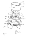
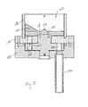
- a preferred embodiment tablet dispenser constructed according to the principles of the present invention is designated by the numeral 100 in the drawings.
- the preferred embodiment tablet dispenser 100 is preferably mounted to the top of the dishwashing machine and used to dispense a product such as a sanitizer in tablet form into a dishwashing machine (not shown) with proof of delivery to the user.
- the tablet dispenser 100 ensures that the use solution including the sanitizer is in the desired range of 50 to 100 ppm after the product tablet is dissolved. Because the environment in which the product tablet is dispensed includes moisture and vapor, it is desirable to isolate the product tablets within the tablet dispenser 100 from the humid environment within the dishwashing machine. It is recognized that the tablet dispenser 100 may be used to dispense many different types of products for use in many different types of applications and is not limited to the products and the applications described herein.
- the present invention could also be used for detergents, rinse aids, fabric softeners, bleaches, optical brightening chemicals, starching chemicals, manual dishwashing products, cleaning products used in spray bottles or mop buckets, laundry products, animal feed supplements, and other suitable products.
- detergents rinse aids, fabric softeners, bleaches, optical brightening chemicals, starching chemicals, manual dishwashing products, cleaning products used in spray bottles or mop buckets, laundry products, animal feed supplements, and other suitable products.
- tablets is used throughout, and it is understood that the term “tablets” includes product in the form of tablets, pellets, granules, or other suitable forms well known in the art.
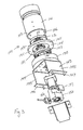
- the tablet dispenser 100 includes a hopper 101, a dispensing mechanism including disk members creating an interrupted flow path through which product tablets 168 are dispensed, a motor or gear head 172 to drive the disk members, an outlet conduit 142, and a sensor mechanism 155 to provide indication of proof of delivery of the product tablets 168.
- the hopper 101 includes a side wall 102, which is preferably a hollow cylindrical housing with a top opening 104, a bottom opening 106, and a cavity 105 configured and arranged to contain the plurality of product tablets 168.
- the hopper 101 is used to store the product tablets 168 and is preferably located above the disk members.
- a wiper 109 may be operatively connected to the side wall 102 of the hopper 101 proximate the bottom of the hopper 101.
- the wiper 109 is preferably a wedge shaped member.
- a fastener (not shown) may be inserted through an aperture 103 in the side wall 102 and an aperture 110 in the wiper 109 to operatively connect the wiper 109 to the hopper 101.
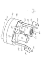
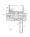
- the first disk member 112 preferably has a diameter slightly smaller than the inside diameter of the bottom of the hopper 101 so that the first disk member 112 fits within the cavity 105 proximate the bottom of the hopper 101.
- a hub 113 is operatively connected to the top of the first disk member 112 proximate the center thereof, and the hub is preferably frustoconical shaped to guide the product tablets 168 away from the center of the first disk member 112 to assist in minimizing the number of un-dispensed product tablets 168.
- Apertures 114 extend longitudinally through the first disk member 112 on opposing sides of the hub 113 proximate the center of the first disk member 112, and dispensing apertures 115 extend longitudinally through the first disk member 112 on opposing sides of the hub 113 proximate the edge of the first disk member 112.
- the dispensing apertures 115 are placed 90 degrees from the apertures 114.
- the dispensing apertures 115 preferably each contain one whole product tablet 168, it is recognized that the product tablets 168 may become broken so the dispensing apertures 115 are configured and arranged to contain the equivalent of one to two product tablets 168, broken and/or whole. Therefore, the term "product tablet” or "product tablets” used throughout includes whole tablets and/or portions of whole tablets.
- two dispensing apertures 115 are shown, it is recognized that one or more dispensing apertures may be used.
- the top of the first disk member 112 may also include dispensing ramps 116, which are declining, sloped grooves approaching the dispensing apertures 115.
- the bottom of the first disk member 112 includes a recess 117 proximate the center of the first disk member 112 below the hub 113.
- the second disk member 120 preferably has a diameter greater than the diameter of the bottom of the hopper 101 and includes a groove 122 into which the bottom of the side wall 102 of the hopper 101 is placed to operatively connect the hopper 101 to the second disk member 120.
- the second disk member 120 and the hopper 101 are preferably stationary.
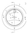
- a bore 121 extends longitudinally through the center of the second disk member 120, and a dispensing aperture 123 extends longitudinally through the second disk member 120 between the bore 121 and the groove 122, more proximate the groove 122, so that the dispensing aperture 123 intermittently aligns with the dispensing apertures 115 of the first disk member 112.
- the second disk member 120 also includes apertures 124 between the groove 122 and the edge of the second disk member 120. There are preferably four apertures 124 approximately 90 degrees apart from one another.
- the wiper 109 mounted to the hopper 101 is also stationary and is preferably positioned proximate the first disk member 112 and aligned with the dispensing aperture 123. As shown in Figures 6 and 7 , the wiper 109 preferably does not contact the hub 113, which guides the product tablets 168 away from the center of the first disk member 112 to assist in minimizing the number of un-dispensed product tablets 168.
- the wiper 109 diverts extraneous product tablets 168 that do not fit within the approaching dispensing aperture 115 away from the dispensing aperture 115 as the dispensing aperture 115 rotates past the wiper 109.
- the dispensing aperture 115 is configured and arranged to contain a predetermined quantity of product tablets.
- the wiper 109 removes excess product tablets 168 proximate the dispensing aperture 115 as the dispensing aperture 115 is rotated proximate the dispensing aperture 123 thereby ensuring a desired number of product tablets 168 is transferred from the dispensing aperture 115 to the dispensing aperture 123 as the first disk member 112 is rotated to align the dispensing aperture 115 with the dispensing aperture 123.
- the wiper 109 ensures that only the desired dosage is dispensed each time one of the dispensing apertures 115 aligns with the dispensing aperture 123.
- the ramp 116 assists in easing the extraneous product tablets 168 away from the dispensing aperture 115 and because the ramp 116 is gradual, the product tablets 168 do not get caught on an edge of the dispensing aperture 115 or crushed between the wiper 109 and the dispensing aperture 115 thereby causing the product tablets 168 to break.
- the wiper 109 eases excess product tablets 168 away from the dispensing aperture 115 along the ramp 116, which reduces the occurrence of breakage of the excess product tablets 168.
- the third disk member 127 includes an upper boss 128 extending upward from the top proximate the center of the third disk member 127 and a lower boss 130 extending downward from the bottom proximate the center of the third disk member 127.
- the upper boss 128 is configured and arranged to extend through the bore 121 of the second disk member 120 and into the recess 117 of the first disk member 112.
- the upper boss 128 includes apertures 129 that align with apertures 114, and a fastener (not shown) is inserted into the apertures 129 and 114 to interconnect the third disk member 127 and the first disk member 112, which are preferably concurrently rotatable while the second disk member 120 is stationary.
- the lower boss 130 includes a notch 131 into which a coupling of a shaft of a motor 172 is inserted and operatively connected to the third disk member 127 to rotate the third disk member 127 and the first disk member 112.
- the third disk member 127 includes preferably two opposing dispensing apertures 132, which are preferably 90 degrees from the dispensing apertures 115 of the first disk member 112, and are intermittently aligned with the dispensing aperture 123.
- the first disk member 112 and the third disk member 127 are preferably concurrently rotated so that when the dispensing aperture 115 is aligned with the dispensing aperture 123, the dispensing aperture 132 is approximately 90 degrees behind the dispensing apertures 115 and 123 and when the dispensing aperture 132 is aligned with the dispensing aperture 123, the dispensing aperture 115 is approximately 90 degrees ahead of the dispensing apertures 123 and 132. Therefore, the dispensing apertures 115 and 132 are preferably approximately 90 degrees apart with respect to the dispensing aperture 123.
- any number of degrees of separation is acceptable as long as there is not a direct flow path with at least a portion of the dispensing apertures 115, 123, and 132.
- the fourth disk member 135, which is optional, is preferably stationary and used to connect the outlet conduit 142 to the tablet dispenser 100.
- the fourth disk member 135 includes a bore 136 extending longitudinally through the center of the fourth disk member 135 and a recess 137 in the top of the fourth disk member 135 proximate the center of the fourth disk member 135.
- the recess 137 is configured and arranged to house the third disk member 127, with the lower boss 130 extending into the bore 136.
- the motor 172 extends into the bore 136 and is operatively connected to the lower boss 130.
- Apertures 138 align with apertures 124 of the second disk member 120 and fasteners (not shown) are inserted into the apertures 138 and 124 to interconnect the fourth disk member 127 and the second disk member 120.
- the fourth disk member 135 also includes a dispensing aperture 139 to which the outlet conduit 142 is operatively connected, and the dispensing aperture 139 is intermittently aligned with the dispensing apertures 132 of the third disk member 127.
- the dispensing aperture 139 is preferably located approximately 180 degrees from the dispensing aperture 123 thereby further isolating the hopper 101 from the outlet conduit 142.
- the outlet conduit 142 is preferably light transmissive meaning transparent and/or translucent.
- the outlet conduit 142 is preferably tubular having an interior surface and an exterior surface. The interior surface is exposed to the humid conditions of the dishwashing machine and the wall of the outlet conduit 142 acts as a barrier protecting the exterior surface from exposure to the humid conditions.
- the disk members execute the dispensing of the product tablets 168 through the respective dispensing apertures in an interrupted flow path to isolate the product tablets 168 within the hopper 101 from moisture and vapor generated by the dishwashing machine.
- the flow path is interrupted because as the disk members rotate there is not a continuous flow of the product tablets 168 from one dispensing aperture to the next dispensing aperture.
- the interrupted flow path "seals" the hopper 101 from the outside elements that have entered the outlet conduit 142.
- the disk members seal the hopper 101 in that the disk members help prevent and limit exposure of the product tablets 168 inside the hopper 101 to moisture and vapor or other outside elements.
- At least three disk members should be used to effectively isolate the hopper 101 from outside elements.
- each dynamic (rotatable) disk member is positioned adjacent a static (stationary) disk member to isolate the hopper 101 from the humid environment of the dishwashing machine.
- the thickness of the first disk member 112 and the diameter of the dispensing aperture 115 are configured and arranged to contain a predetermined quantity of product tablets 168 thereby ensuring that the desired dosage is dispensed.
- the diameter and the height of the dispensing aperture 115 define a volume in which the product tablets 168 are contained thereby selecting the dose of product tablets 168.
- the subsequent disk members are preferably thicker than the first disk member 112 and each subsequent dispensing aperture in the flow path has a diameter that is preferably slightly larger than the previous dispensing aperture diameter.
- the thicker disk members and the increasingly larger dispensing aperture diameters assist in preventing jamming of the dispenser as the product tablets are dispensed because the volumes in which the product tablets are contained increase as they move through the flow path.
- the diameters of the dispensing apertures are tapered or at least countersunk so that the top of each dispensing aperture is smaller than the bottom of each dispensing aperture.
- the preferred embodiment includes at least one static disk member and at least two dynamic disk members to isolate the hopper 101 from the humid environment of the dishwashing machine, it is recognized that additional disk members could be used to further isolate the hopper.
- the dispensing apertures could be any size or shape to accommodate varying sizes and shapes of product tablets.
- seal rings could be machined or molded directly onto the disk members to create a seal between the disks. It is also recognized that O-rings could be used to seal each of the dispensing apertures of the disk members against the adjacent disk member.
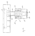
- a frame 143 may be used to elevate the tablet dispenser 100 with respect to the mounting surface, such as a dishwashing machine, to accommodate the motor 172 and the sensor mechanism 155.
- the frame 143 is preferably an upside down U-shaped member having outward extending support members on each end.
- the frame 143 includes a top 144 with two sides 145 extending downward from two opposing sides of the top 144 and a flange 146 extending outward from each side 145.
- the top 144 supports the hopper 101 and the disk members, and the flanges 146 support the frame 143 on the mounting surface.
- Connectors 147 such as bolts or other suitable fasteners may be used to connect the flanges 146 of the frame 143 to the mounting surface.
- the preferred sensor mechanism 155 is an infrared light sensor including an emitter 156 and a receiver 157 operatively connected to a housing 158 proximate the outlet conduit 142 to provide indication of proof of delivery of the product tablets 168 into the dishwashing machine.
- the emitter 156 emits a light beam and the receiver 157 receives the light beam from the emitter 156.
- a capacitive sensor does not require an optical transmission and includes two electrodes with a signal in between the two electrodes. The signal changes when an object is proximate the signal. The electrodes would be mounted outside the tubing, and the sensitivity of the signal would be adjusted to not sense the tubing.
- the housing 158 is preferably an upside down T-shaped tubular member including a first ledge 159 for supporting the emitter 156, a second ledge 160 for supporting the receiver 157, and a bore 162 through which the outlet conduit 142 extends.
- the housing 158 also includes a lateral aperture 161 on each side of the housing 158, each lateral aperture 161 extending into the bore 162 to allow the beam of light being emitted from the emitter 156 and received by the receiver 157 to be transmitted through the housing and the outlet conduit 142.
- Fasteners (not shown) may be inserted into apertures 164 to secure and seal the housing 158 to the mounting surface such as a dishwashing machine.
- the bottom of the housing 158 may also include circular grooves 163 around the bore 162 for O-rings (not shown) to seal the housing 158, and therefore the outlet conduit 142, from humid conditions inside the dishwashing machine.
- the outlet conduit 142 extends from the tablet dispenser 100 to the dishwashing machine, and the sensor mechanism 155 operates through the outlet conduit 142.
- the beam of light is emitted and received through the outlet conduit 142. Because the O-ring seals the outlet conduit 142 to the dishwashing machine, the moisture and vapors within the dishwashing machine do not escape proximate the outlet conduit 142 and the sensor mechanism 155 is protected from the humid conditions inside the dishwashing machine.
- Some possible contaminants that may interfere with the operation of the sensor mechanism 155 include various types of residue such as condensation, portions of the product tablet(s), and residual product.
- capillary action may cause the chemical laden moisture to seep up the outside of the outlet conduit 142 to the sensor mechanism 155 and eventually block the sensor mechanism 155.
- Sealing the outlet conduit 142 to the dishwashing machine helps prevent this from happening.
- Sealing the outlet conduit 142 to the housing 158 isolates the components of the sensor mechanism 155, including the emitter 156, the receiver 157, and the apertures 161 through which the beam of light passes. This isolation prevents the buildup of residual product and/or chemical exposure, which could obstruct the operation of the sensor mechanism 155.
- the sensor mechanism 155 preferably has a relatively high speed response time, preferably a 1 ms response time.
- the inside diameter of the outlet conduit 142 should be small enough so that the product tablet 168 dispensed through the outlet conduit 142 will pass through the light beam transmitted through the outlet conduit 142 to interrupt the receipt of the light beam by the receiver 157.
- the inside diameter of the outlet conduit 142 is slightly less than double the smallest product tablet dimension.
- a container of product tablets 168 is docked onto the hopper 101.
- a signal is provided to the tablet dispenser 100 to dispense product at the desired time. If the tablet dispenser 100 is used with a dishwashing machine to dispense a sanitizing product, the dishwashing machine will signal delivery of the product tablet 168 for the sanitizing rinse cycle of the dishwashing machine.
- Power is applied to the motor 172 or gear head to begin rotation of the dynamic disk members 112 and 127. Rotation of the disk member 112 assists in the first dispensing aperture 115 receiving a product tablet 168 within the hopper 101, as shown in Figure 8 .
- the first dispensing aperture 115 of the first disk member 112 aligns with the second dispensing aperture 123 of the second disk member 120 and the product tablet 168 is transferred from the first dispensing aperture 115 to the second dispensing aperture 123, as shown in Figure 9 .
- the wiper 109 blocks additional product tablets 168 from entering the first dispensing aperture 115 when aligned with the second dispensing aperture 123.
- the third dispensing aperture 132 aligns with the second dispensing aperture 123 and the product tablet 168 is transferred from the second dispensing aperture 123 to the third dispensing aperture 132, as shown in Figure 10 .
- the third dispensing aperture 132 and the first dispensing aperture 115 are positioned at different locations with respect to the second dispensing aperture 123 thereby aligning with the second dispensing aperture 123 at separate times resulting in an interrupted flow path for the product tablets 168.
- the third dispensing aperture 132 aligns with the fourth dispensing aperture 139 of the fourth disk member 135 and the product tablet 168 is transferred from the third dispensing aperture 132 to the fourth dispensing aperture 139, as shown in Figure 11 .
- the fourth dispensing aperture 139 is in fluid communication with the outlet conduit 142, and the product tablet 168 is then dispensed through the outlet conduit 142 into the dishwashing machine.
- the sensor mechanism 155 detects the delivery of the product tablet 168 into the dishwashing machine.
- the motor 172 or gear head is stopped and a delivery message is displayed. If no product tablet 168 is sensed within a specified time period, the motor 172 is stopped and an out of product message is displayed indicating that another container of product tablets 168 needs to be installed.
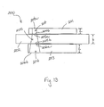
- Figure 13 shows a schematic drawing of three disk members having dispensing apertures of another embodiment tablet dispenser 200.
- the first disk member 201 preferably has a thickness a between 3/8 and 1/2 inch
- the second disk member 202 and the third disk member 203 preferably each have a thickness larger than the thickness of the first disk member 201.
- the thickness b of the second disk member 202 and the thickness c of the third disk member 203 are between 3/4 and 7/8 inch.
- the first disk member 201 includes a first dispensing aperture 204
- the second disk member 202 includes a second dispensing aperture 205
- the third disk member includes a third dispensing aperture 206.
- the first dispensing aperture 204 has a diameter configured and arranged to contain a predetermined quantity of product tablets thereby assisting in dispensing the desired dose of product.
- the second dispensing aperture 205 has a diameter larger than the diameter of the first dispensing aperture 204
- the third dispensing aperture 206 has a diameter larger than the diameter of the second dispensing aperture 205.
- the dispensing apertures are tapered with a smaller diameter top and a larger diameter bottom, the adjacent tops and bottoms being approximately the same diameter. This ensures that there is more room for the product tablets proximate the bottom of each disk member, which assists in preventing jamming of the product tablets and assists in dispensing of the product tablets.
- the first dispensing aperture 204 of the first disk member 201 may or may not be tapered.
- the dispensing aperture 204 preferably has a top diameter 204a and a bottom diameter 204b of slightly greater than 3/8 inch, preferably approximately 0.438 inch.
- the dispensing aperture 205 preferably has a top diameter 205a of approximately the same as the diameters 204a and 204b and a bottom diameter 205b of approximately 0.503 inch.
- the dispensing aperture 206 preferably has a top diameter 206a of approximately the same as the diameter 205b and a bottom diameter 206b of approximately 0.566 inch.
- the preferred diameters may be +/- 0.020 inch.
- the thickness of the second disk member 202 and the third disk member 203 are larger than the thickness of the first disk member 201 and the diameters of the dispensing apertures increase. Therefore, the volumes of the dispensing apertures increase, which assists in reducing the occurrence of the product tablets jamming in the tablet dispenser 200. If the dispensing apertures are tapered, this further reduces the occurrence of the product tablets jamming in the table dispenser 200.
Landscapes
- Chemical & Material Sciences (AREA)
- Chemical Kinetics & Catalysis (AREA)
- Medical Preparation Storing Or Oral Administration Devices (AREA)
- Filling Or Emptying Of Bunkers, Hoppers, And Tanks (AREA)
- Feeding Of Articles To Conveyors (AREA)
- Supply Of Fluid Materials To The Packaging Location (AREA)
Applications Claiming Priority (2)
| Application Number | Priority Date | Filing Date | Title |
|---|---|---|---|
| US10/862,925 US7896195B2 (en) | 2004-06-08 | 2004-06-08 | Tablet dispenser with isolated product hopper |
| PCT/US2005/010349 WO2005122861A1 (en) | 2004-06-08 | 2005-03-28 | Tablet dispenser with isolated product hopper |
Publications (2)
| Publication Number | Publication Date |
|---|---|
| EP1755434A1 EP1755434A1 (en) | 2007-02-28 |
| EP1755434B1 true EP1755434B1 (en) | 2011-10-12 |
Family
ID=34964210
Family Applications (1)
| Application Number | Title | Priority Date | Filing Date |
|---|---|---|---|
| EP05730773A Expired - Lifetime EP1755434B1 (en) | 2004-06-08 | 2005-03-28 | Tablet dispenser with isolated product hopper |
Country Status (10)
| Country | Link |
|---|---|
| US (1) | US7896195B2 (enExample) |
| EP (1) | EP1755434B1 (enExample) |
| JP (1) | JP4891244B2 (enExample) |
| AT (1) | ATE527930T1 (enExample) |
| AU (1) | AU2005253925B2 (enExample) |
| BR (1) | BRPI0510555B1 (enExample) |
| CA (1) | CA2566618C (enExample) |
| ES (1) | ES2372288T3 (enExample) |
| MX (1) | MXPA06013959A (enExample) |
| WO (1) | WO2005122861A1 (enExample) |
Families Citing this family (30)
| Publication number | Priority date | Publication date | Assignee | Title |
|---|---|---|---|---|
| US7219703B2 (en) * | 2004-02-03 | 2007-05-22 | Kirby Lester, Llc | Rotating multi-chamber tablet feeder |
| US7456821B2 (en) * | 2004-11-30 | 2008-11-25 | Immersion Corporation | User interface device |
| ES2432539T3 (es) * | 2007-02-19 | 2013-12-04 | Teijin Pharma Limited | Tabla de transferencia |
| ITTO20070598A1 (it) | 2007-08-10 | 2009-02-11 | Eltek Spa | Dispositivo dispensatore, particolarmente per apparati domestici |
| US20090173747A1 (en) * | 2008-01-04 | 2009-07-09 | Paul Andrew Reynolds | Bead craft system |
| US8430269B2 (en) * | 2008-09-30 | 2013-04-30 | Jvm Co., Ltd. | Tablet cassette of automatic tablet packing apparatus |
| US20100140287A1 (en) * | 2008-12-08 | 2010-06-10 | Jerral Richardson | "Dispenser, system and method for dispensing pills" |
| US20100318218A1 (en) * | 2009-06-15 | 2010-12-16 | Muncy Jr Robert B | Pill Dispenser and Method |
| JP2012154755A (ja) * | 2011-01-26 | 2012-08-16 | Hitachi High-Technologies Corp | 反応容器閉栓装置,自動分析装置,反応容器閉栓方法 |
| US8931311B2 (en) | 2011-04-26 | 2015-01-13 | General Electric Company | Additive dispenser for a washing machine |
| JP5795966B2 (ja) * | 2012-01-30 | 2015-10-14 | 株式会社吉野工業所 | 容器 |
| US9481482B2 (en) * | 2012-05-30 | 2016-11-01 | Multisorb Technologies, Inc. | Article dispensing |
| US8950625B2 (en) * | 2012-05-30 | 2015-02-10 | Multisorb Technologies, Inc. | Article dispensing |
| ITBO20130315A1 (it) * | 2013-06-21 | 2014-12-22 | Ima Ind Srl | Unita¿ e metodo di riempimento di elementi di contenimento di capsule monouso per bevande da estrazione o infusione |
| DE102016210399A1 (de) * | 2016-06-13 | 2017-12-14 | BSH Hausgeräte GmbH | Dosiervorrichtung für Reinigungsmittel-Formkörper in Haushalts-Geschirrspülmaschinen |
| WO2017215835A1 (de) | 2016-06-13 | 2017-12-21 | BSH Hausgeräte GmbH | Dosiervorrichtung für reinigungsmittel-formkörper in haushalts-geschirrspülmaschinen |
| US10512387B2 (en) * | 2016-09-30 | 2019-12-24 | Haier Us Appliance Solutions, Inc. | Hydraulically actuated diverter for an appliance |
| DE102017208702A1 (de) | 2017-05-23 | 2018-11-29 | BSH Hausgeräte GmbH | Dosiervorrichtung und Haushalts-Geschirrspülmaschine |
| US10478276B2 (en) | 2017-08-11 | 2019-11-19 | World Wildlife Fund, Inc. | Pellet delivery mechanism |
| WO2019067646A1 (en) * | 2017-09-26 | 2019-04-04 | Yesudasan Sujith | Pill dispensing canister |
| USD891003S1 (en) * | 2019-01-18 | 2020-07-21 | All Seasons Feeders, Ltd. | Conversion system |
| US11497380B2 (en) | 2019-06-19 | 2022-11-15 | Midea Group Co., Ltd. | Detergent cartridge for a dishwasher incorporating detergent dispensing verification |
| US11103120B2 (en) | 2019-06-19 | 2021-08-31 | Midea Group Co., Ltd. | Detergent cartridge for a dishwasher |
| CN110742562B (zh) * | 2019-11-19 | 2021-04-20 | 佛山市顺德区美的洗涤电器制造有限公司 | 分配器和洗涤电器 |
| GB202004831D0 (en) * | 2020-04-01 | 2020-05-13 | Ondosis Ab | Delivery device for oral dosage forms |
| JP7581702B2 (ja) * | 2020-08-24 | 2024-11-13 | セイコーエプソン株式会社 | 可塑化装置、射出成形装置、および三次元造形装置 |
| US11857505B2 (en) | 2020-10-05 | 2024-01-02 | Express Scripts Strategic Development, Inc. | Smart pill dispenser |
| US12036185B2 (en) | 2021-07-19 | 2024-07-16 | Optum, Inc. | System and method to count pills |
| US12311282B2 (en) | 2022-01-01 | 2025-05-27 | Spin Master Ltd. | Kit with plurality of blocks for constructing craft |
| US20250289647A1 (en) * | 2024-03-12 | 2025-09-18 | Kristi Nixon Brown | Pill dispensing assembly and module including the same |
Family Cites Families (41)
| Publication number | Priority date | Publication date | Assignee | Title |
|---|---|---|---|---|
| US2664223A (en) | 1950-05-20 | 1953-12-29 | Dobkin Israel Todd | Can with built-in dispenser |
| DE1403674A1 (de) | 1961-02-22 | 1968-10-24 | Siemens Elektorgeraete Gmbh | Dosiereinrichtung fuer Geschirrspuel- und Waschmaschinen |
| US3410450A (en) | 1967-06-16 | 1968-11-12 | Jerry A. Fortenberry | Sanitary pill dispenser with indicator |
| US3785525A (en) | 1972-01-31 | 1974-01-15 | Safe Well Mfg Co | Chemical tablet dispensing device for wells |
| US4150766A (en) * | 1977-03-18 | 1979-04-24 | Knorr Robert H | Dispensing apparatus |
| JPS5717732A (en) * | 1980-07-03 | 1982-01-29 | Sawada Kogyosho Yuugen | Paper cup with cover and winding fastening machine for cover of paper cup |
| US4405060A (en) | 1981-07-20 | 1983-09-20 | American Hospital Supply Corporation | Tablet dispensing device |
| JPS58207582A (ja) * | 1982-05-25 | 1983-12-03 | Toray Ind Inc | たて型ロ−タリ−バルブ |
| US4573606A (en) | 1983-09-12 | 1986-03-04 | Kermit E. Lewis | Automatic pill dispenser and method of administering medical pills |
| DE3344412A1 (de) * | 1983-12-08 | 1985-06-20 | Henkel KGaA, 4000 Düsseldorf | Dosierspender |
| US4711370A (en) | 1984-09-28 | 1987-12-08 | Autotrol Corporation | Seal member for pellet dispenser |
| FI88112C (fi) | 1985-07-30 | 1993-04-13 | Glaxo Group Ltd | Anordning foer administrering av laekemedel till patienter |
| US4694900A (en) | 1985-08-05 | 1987-09-22 | B & B Chlorination | Dry pellet dispensing device for wells |
| US4676399A (en) | 1985-10-11 | 1987-06-30 | Burckhardt Lennie L | Dry pellet dispensing apparatus |
| US4832235A (en) * | 1987-05-11 | 1989-05-23 | Palmer Warren C | Self-measuring condiment cap |
| GB8717407D0 (en) | 1987-07-23 | 1987-08-26 | Diversey Corp | Dispenser |
| US5014877A (en) * | 1989-10-30 | 1991-05-14 | Autotrol Corporation | Pellet dispenser |
| US5064094A (en) | 1989-10-30 | 1991-11-12 | Autotrol Corporation | Pellet dispensing unit |
| US5078299A (en) | 1991-02-07 | 1992-01-07 | Keating Scott P | Apparatus for the periodic and controlled dispensing of tablets such as chlorine pellets |
| US5243970A (en) * | 1991-04-15 | 1993-09-14 | Schering Corporation | Dosing device for administering metered amounts of powdered medicaments to patients |
| US5323929A (en) * | 1992-12-09 | 1994-06-28 | Marlar Warner B | Medicine dispenser |
| FR2713605B1 (fr) * | 1993-12-14 | 1996-01-12 | Benarrouch Jacques | Dispositif de prélèvement et comptage cyclique de composants identiques, sphériques ou assimilés. |
| US5522525A (en) * | 1994-12-02 | 1996-06-04 | Nu-Box, Inc. | Medication dispenser station |
| DE4446882B4 (de) | 1994-12-27 | 2004-02-12 | BSH Bosch und Siemens Hausgeräte GmbH | Vorrichtung zum wiederholten, selbständigen Dosieren von genau dosierten Mengen eines pulverförmigen Reinigungsmittels in wasserführenden Reinigungsmaschinen insbesondere Haushalt-Geschirrspülmaschinen und Haushalt-Waschmaschinen |
| JP3524606B2 (ja) * | 1994-12-28 | 2004-05-10 | 三洋電機株式会社 | 固形製剤充填装置 |
| US5636470A (en) | 1995-02-13 | 1997-06-10 | Farnam Companies, Inc. | Device for the controlled dispensing of pellets |
| DE19540958A1 (de) | 1995-11-03 | 1997-05-07 | Aeg Hausgeraete Gmbh | Dosiervorrichtung |
| IT237277Y1 (it) * | 1995-11-10 | 2000-09-05 | Rossi S R L G | Apparecchiatura perfezionata per la fabbricazione di cialde dipolvere di caffe' |
| DE19652787A1 (de) | 1996-12-19 | 1998-07-30 | Sita Mestechnik Gmbh I G | Einrichtung zum volumetrischen Dosieren eines pulverförmigen oder granulierten Reinigungsmittels in wasserführenden Reinigungsmaschinen, insbesondere für Haushaltwaschmaschinen oder Geschirrspüler |
| US6601729B1 (en) | 1999-03-26 | 2003-08-05 | Papp Enterprises, Llc | Automated portable medication radial dispensing apparatus and method using a carrier tape |
| US6547097B1 (en) | 1999-05-27 | 2003-04-15 | The Knight Group Llc | Dispensing apparatus and method |
| KR100341275B1 (ko) | 1999-08-02 | 2002-06-21 | 이대식 | 엉킴 방지 분배기 |
| US6283339B1 (en) * | 2000-03-31 | 2001-09-04 | Sonoco Development, Inc. | Twist bottom dispenser |
| EP1159913B1 (de) | 2000-06-02 | 2004-08-18 | Chemische Fabrik Dr. Weigert GmbH & Co KG | Dosiereinrichtung für Geschirrspülreinigertabletten |
| US6497342B2 (en) * | 2000-11-30 | 2002-12-24 | Mckesson Automated Healthcare, Inc. | Medicine feeder |
| GB0101983D0 (en) | 2001-01-25 | 2001-03-14 | Unilever Plc | Detergent dispenser system |
| US6701944B2 (en) | 2001-01-25 | 2004-03-09 | Unilever Home & Personal Care Usa, Division Of Conopco, Inc. | Detergent dispenser system |
| US6450371B1 (en) | 2002-01-24 | 2002-09-17 | Yury Sherman | Device for measuring, dispensing and storing of granular and powder materials |
| US6962266B2 (en) | 2002-10-04 | 2005-11-08 | Ecolab Inc. | Method and apparatus for using a unit dose dispenser |
| US7219703B2 (en) | 2004-02-03 | 2007-05-22 | Kirby Lester, Llc | Rotating multi-chamber tablet feeder |
| US6929159B1 (en) * | 2004-11-24 | 2005-08-16 | Voy Haig | Quantitative measuring dispenser |
-
2004
- 2004-06-08 US US10/862,925 patent/US7896195B2/en active Active
-
2005
- 2005-03-28 AU AU2005253925A patent/AU2005253925B2/en not_active Ceased
- 2005-03-28 WO PCT/US2005/010349 patent/WO2005122861A1/en not_active Ceased
- 2005-03-28 AT AT05730773T patent/ATE527930T1/de not_active IP Right Cessation
- 2005-03-28 EP EP05730773A patent/EP1755434B1/en not_active Expired - Lifetime
- 2005-03-28 BR BRPI0510555A patent/BRPI0510555B1/pt active IP Right Grant
- 2005-03-28 JP JP2007527212A patent/JP4891244B2/ja not_active Expired - Lifetime
- 2005-03-28 MX MXPA06013959A patent/MXPA06013959A/es active IP Right Grant
- 2005-03-28 CA CA2566618A patent/CA2566618C/en not_active Expired - Lifetime
- 2005-03-28 ES ES05730773T patent/ES2372288T3/es not_active Expired - Lifetime
Also Published As
| Publication number | Publication date |
|---|---|
| EP1755434A1 (en) | 2007-02-28 |
| CA2566618A1 (en) | 2005-12-29 |
| BRPI0510555A (pt) | 2007-11-20 |
| WO2005122861A1 (en) | 2005-12-29 |
| JP4891244B2 (ja) | 2012-03-07 |
| BRPI0510555B1 (pt) | 2017-03-14 |
| US7896195B2 (en) | 2011-03-01 |
| ATE527930T1 (de) | 2011-10-15 |
| MXPA06013959A (es) | 2007-03-15 |
| ES2372288T3 (es) | 2012-01-18 |
| AU2005253925B2 (en) | 2010-07-01 |
| JP2008501599A (ja) | 2008-01-24 |
| US20050269346A1 (en) | 2005-12-08 |
| AU2005253925A1 (en) | 2005-12-29 |
| CA2566618C (en) | 2012-05-15 |
Similar Documents
| Publication | Publication Date | Title |
|---|---|---|
| EP1755433B1 (en) | Tablet dispenser with isolated delivery sensor | |
| EP1755434B1 (en) | Tablet dispenser with isolated product hopper | |
| US10569286B2 (en) | Shaped cartridge dispensing systems | |
| US6786356B2 (en) | Drinks machine | |
| US6540081B2 (en) | Unit dose blister pack product dispenser | |
| KR101056591B1 (ko) | 정제 불출 장치 | |
| WO1991006496A1 (en) | Pellet dispenser | |
| AU2016297089B2 (en) | Solid product dispenser for small volume applications | |
| US20080314935A1 (en) | Dispenser for Laundry Chemicals | |
| US4936331A (en) | Dispenser arrangement for a liquid treatment agent in a dish-washer | |
| EP3440436B1 (en) | Apparatus and method for dosaging powdered or granulated material | |
| EP3790650B1 (en) | Dispenser and solution dispensing method |
Legal Events
| Date | Code | Title | Description |
|---|---|---|---|
| PUAI | Public reference made under article 153(3) epc to a published international application that has entered the european phase |
Free format text: ORIGINAL CODE: 0009012 |
|
| 17P | Request for examination filed |
Effective date: 20061117 |
|
| AK | Designated contracting states |
Kind code of ref document: A1 Designated state(s): AT BE BG CH CY CZ DE DK EE ES FI FR GB GR HU IE IS IT LI LT LU MC NL PL PT RO SE SI SK TR |
|
| DAX | Request for extension of the european patent (deleted) | ||
| 17Q | First examination report despatched |
Effective date: 20101207 |
|
| GRAP | Despatch of communication of intention to grant a patent |
Free format text: ORIGINAL CODE: EPIDOSNIGR1 |
|
| GRAS | Grant fee paid |
Free format text: ORIGINAL CODE: EPIDOSNIGR3 |
|
| GRAA | (expected) grant |
Free format text: ORIGINAL CODE: 0009210 |
|
| AK | Designated contracting states |
Kind code of ref document: B1 Designated state(s): AT BE BG CH CY CZ DE DK EE ES FI FR GB GR HU IE IS IT LI LT LU MC NL PL PT RO SE SI SK TR |
|
| REG | Reference to a national code |
Ref country code: GB Ref legal event code: FG4D |
|
| REG | Reference to a national code |
Ref country code: CH Ref legal event code: EP |
|
| REG | Reference to a national code |
Ref country code: IE Ref legal event code: FG4D |
|
| REG | Reference to a national code |
Ref country code: DE Ref legal event code: R096 Ref document number: 602005030565 Country of ref document: DE Effective date: 20111208 |
|
| REG | Reference to a national code |
Ref country code: ES Ref legal event code: FG2A Ref document number: 2372288 Country of ref document: ES Kind code of ref document: T3 Effective date: 20120118 |
|
| REG | Reference to a national code |
Ref country code: NL Ref legal event code: VDEP Effective date: 20111012 |
|
| LTIE | Lt: invalidation of european patent or patent extension |
Effective date: 20111012 |
|
| REG | Reference to a national code |
Ref country code: AT Ref legal event code: MK05 Ref document number: 527930 Country of ref document: AT Kind code of ref document: T Effective date: 20111012 |
|
| PG25 | Lapsed in a contracting state [announced via postgrant information from national office to epo] |
Ref country code: BE Free format text: LAPSE BECAUSE OF FAILURE TO SUBMIT A TRANSLATION OF THE DESCRIPTION OR TO PAY THE FEE WITHIN THE PRESCRIBED TIME-LIMIT Effective date: 20111012 Ref country code: IS Free format text: LAPSE BECAUSE OF FAILURE TO SUBMIT A TRANSLATION OF THE DESCRIPTION OR TO PAY THE FEE WITHIN THE PRESCRIBED TIME-LIMIT Effective date: 20120212 Ref country code: LT Free format text: LAPSE BECAUSE OF FAILURE TO SUBMIT A TRANSLATION OF THE DESCRIPTION OR TO PAY THE FEE WITHIN THE PRESCRIBED TIME-LIMIT Effective date: 20111012 |
|
| PG25 | Lapsed in a contracting state [announced via postgrant information from national office to epo] |
Ref country code: PT Free format text: LAPSE BECAUSE OF FAILURE TO SUBMIT A TRANSLATION OF THE DESCRIPTION OR TO PAY THE FEE WITHIN THE PRESCRIBED TIME-LIMIT Effective date: 20120213 Ref country code: SE Free format text: LAPSE BECAUSE OF FAILURE TO SUBMIT A TRANSLATION OF THE DESCRIPTION OR TO PAY THE FEE WITHIN THE PRESCRIBED TIME-LIMIT Effective date: 20111012 Ref country code: GR Free format text: LAPSE BECAUSE OF FAILURE TO SUBMIT A TRANSLATION OF THE DESCRIPTION OR TO PAY THE FEE WITHIN THE PRESCRIBED TIME-LIMIT Effective date: 20120113 Ref country code: SI Free format text: LAPSE BECAUSE OF FAILURE TO SUBMIT A TRANSLATION OF THE DESCRIPTION OR TO PAY THE FEE WITHIN THE PRESCRIBED TIME-LIMIT Effective date: 20111012 Ref country code: NL Free format text: LAPSE BECAUSE OF FAILURE TO SUBMIT A TRANSLATION OF THE DESCRIPTION OR TO PAY THE FEE WITHIN THE PRESCRIBED TIME-LIMIT Effective date: 20111012 |
|
| PG25 | Lapsed in a contracting state [announced via postgrant information from national office to epo] |
Ref country code: CY Free format text: LAPSE BECAUSE OF FAILURE TO SUBMIT A TRANSLATION OF THE DESCRIPTION OR TO PAY THE FEE WITHIN THE PRESCRIBED TIME-LIMIT Effective date: 20111012 |
|
| PG25 | Lapsed in a contracting state [announced via postgrant information from national office to epo] |
Ref country code: BG Free format text: LAPSE BECAUSE OF FAILURE TO SUBMIT A TRANSLATION OF THE DESCRIPTION OR TO PAY THE FEE WITHIN THE PRESCRIBED TIME-LIMIT Effective date: 20120112 Ref country code: DK Free format text: LAPSE BECAUSE OF FAILURE TO SUBMIT A TRANSLATION OF THE DESCRIPTION OR TO PAY THE FEE WITHIN THE PRESCRIBED TIME-LIMIT Effective date: 20111012 Ref country code: EE Free format text: LAPSE BECAUSE OF FAILURE TO SUBMIT A TRANSLATION OF THE DESCRIPTION OR TO PAY THE FEE WITHIN THE PRESCRIBED TIME-LIMIT Effective date: 20111012 Ref country code: CZ Free format text: LAPSE BECAUSE OF FAILURE TO SUBMIT A TRANSLATION OF THE DESCRIPTION OR TO PAY THE FEE WITHIN THE PRESCRIBED TIME-LIMIT Effective date: 20111012 Ref country code: SK Free format text: LAPSE BECAUSE OF FAILURE TO SUBMIT A TRANSLATION OF THE DESCRIPTION OR TO PAY THE FEE WITHIN THE PRESCRIBED TIME-LIMIT Effective date: 20111012 |
|
| PLBE | No opposition filed within time limit |
Free format text: ORIGINAL CODE: 0009261 |
|
| STAA | Information on the status of an ep patent application or granted ep patent |
Free format text: STATUS: NO OPPOSITION FILED WITHIN TIME LIMIT |
|
| PG25 | Lapsed in a contracting state [announced via postgrant information from national office to epo] |
Ref country code: RO Free format text: LAPSE BECAUSE OF FAILURE TO SUBMIT A TRANSLATION OF THE DESCRIPTION OR TO PAY THE FEE WITHIN THE PRESCRIBED TIME-LIMIT Effective date: 20111012 Ref country code: PL Free format text: LAPSE BECAUSE OF FAILURE TO SUBMIT A TRANSLATION OF THE DESCRIPTION OR TO PAY THE FEE WITHIN THE PRESCRIBED TIME-LIMIT Effective date: 20111012 |
|
| 26N | No opposition filed |
Effective date: 20120713 |
|
| PG25 | Lapsed in a contracting state [announced via postgrant information from national office to epo] |
Ref country code: MC Free format text: LAPSE BECAUSE OF NON-PAYMENT OF DUE FEES Effective date: 20120331 |
|
| REG | Reference to a national code |
Ref country code: CH Ref legal event code: PL |
|
| REG | Reference to a national code |
Ref country code: DE Ref legal event code: R097 Ref document number: 602005030565 Country of ref document: DE Effective date: 20120713 |
|
| REG | Reference to a national code |
Ref country code: IE Ref legal event code: MM4A |
|
| PG25 | Lapsed in a contracting state [announced via postgrant information from national office to epo] |
Ref country code: LI Free format text: LAPSE BECAUSE OF NON-PAYMENT OF DUE FEES Effective date: 20120331 Ref country code: CH Free format text: LAPSE BECAUSE OF NON-PAYMENT OF DUE FEES Effective date: 20120331 Ref country code: AT Free format text: LAPSE BECAUSE OF FAILURE TO SUBMIT A TRANSLATION OF THE DESCRIPTION OR TO PAY THE FEE WITHIN THE PRESCRIBED TIME-LIMIT Effective date: 20111012 Ref country code: IE Free format text: LAPSE BECAUSE OF NON-PAYMENT OF DUE FEES Effective date: 20120328 |
|
| PG25 | Lapsed in a contracting state [announced via postgrant information from national office to epo] |
Ref country code: FI Free format text: LAPSE BECAUSE OF FAILURE TO SUBMIT A TRANSLATION OF THE DESCRIPTION OR TO PAY THE FEE WITHIN THE PRESCRIBED TIME-LIMIT Effective date: 20111012 |
|
| REG | Reference to a national code |
Ref country code: DE Ref legal event code: R082 Ref document number: 602005030565 Country of ref document: DE Representative=s name: GODEMEYER BLUM LENZE PATENTANWAELTE, PARTNERSC, DE Ref country code: DE Ref legal event code: R082 Ref document number: 602005030565 Country of ref document: DE Representative=s name: GODEMEYER BLUM LENZE PARTNERSCHAFT, PATENTANWA, DE |
|
| PG25 | Lapsed in a contracting state [announced via postgrant information from national office to epo] |
Ref country code: TR Free format text: LAPSE BECAUSE OF FAILURE TO SUBMIT A TRANSLATION OF THE DESCRIPTION OR TO PAY THE FEE WITHIN THE PRESCRIBED TIME-LIMIT Effective date: 20111012 |
|
| PG25 | Lapsed in a contracting state [announced via postgrant information from national office to epo] |
Ref country code: LU Free format text: LAPSE BECAUSE OF NON-PAYMENT OF DUE FEES Effective date: 20120328 |
|
| PG25 | Lapsed in a contracting state [announced via postgrant information from national office to epo] |
Ref country code: HU Free format text: LAPSE BECAUSE OF FAILURE TO SUBMIT A TRANSLATION OF THE DESCRIPTION OR TO PAY THE FEE WITHIN THE PRESCRIBED TIME-LIMIT Effective date: 20050328 |
|
| REG | Reference to a national code |
Ref country code: FR Ref legal event code: PLFP Year of fee payment: 11 |
|
| REG | Reference to a national code |
Ref country code: FR Ref legal event code: PLFP Year of fee payment: 12 |
|
| REG | Reference to a national code |
Ref country code: FR Ref legal event code: PLFP Year of fee payment: 13 |
|
| REG | Reference to a national code |
Ref country code: FR Ref legal event code: PLFP Year of fee payment: 14 |
|
| PGFP | Annual fee paid to national office [announced via postgrant information from national office to epo] |
Ref country code: DE Payment date: 20240130 Year of fee payment: 20 Ref country code: GB Payment date: 20240108 Year of fee payment: 20 |
|
| PGFP | Annual fee paid to national office [announced via postgrant information from national office to epo] |
Ref country code: IT Payment date: 20240212 Year of fee payment: 20 Ref country code: FR Payment date: 20240213 Year of fee payment: 20 |
|
| PGFP | Annual fee paid to national office [announced via postgrant information from national office to epo] |
Ref country code: ES Payment date: 20240408 Year of fee payment: 20 |
|
| REG | Reference to a national code |
Ref country code: DE Ref legal event code: R071 Ref document number: 602005030565 Country of ref document: DE |
|
| REG | Reference to a national code |
Ref country code: ES Ref legal event code: FD2A Effective date: 20250404 |
|
| REG | Reference to a national code |
Ref country code: GB Ref legal event code: PE20 Expiry date: 20250327 |
|
| PG25 | Lapsed in a contracting state [announced via postgrant information from national office to epo] |
Ref country code: ES Free format text: LAPSE BECAUSE OF EXPIRATION OF PROTECTION Effective date: 20250329 |
|
| PG25 | Lapsed in a contracting state [announced via postgrant information from national office to epo] |
Ref country code: GB Free format text: LAPSE BECAUSE OF EXPIRATION OF PROTECTION Effective date: 20250327 |