EP1752602A2 - Fenêtre coulissante et soulevable - Google Patents
Fenêtre coulissante et soulevable Download PDFInfo
- Publication number
- EP1752602A2 EP1752602A2 EP06116471A EP06116471A EP1752602A2 EP 1752602 A2 EP1752602 A2 EP 1752602A2 EP 06116471 A EP06116471 A EP 06116471A EP 06116471 A EP06116471 A EP 06116471A EP 1752602 A2 EP1752602 A2 EP 1752602A2
- Authority
- EP
- European Patent Office
- Prior art keywords
- frame
- guide
- window
- rack
- movement
- Prior art date
- Legal status (The legal status is an assumption and is not a legal conclusion. Google has not performed a legal analysis and makes no representation as to the accuracy of the status listed.)
- Granted
Links
- 230000007704 transition Effects 0.000 claims description 5
- 238000000926 separation method Methods 0.000 claims description 3
- 230000007246 mechanism Effects 0.000 description 7
- 238000009434 installation Methods 0.000 description 5
- 238000007789 sealing Methods 0.000 description 5
- 230000008901 benefit Effects 0.000 description 3
- 230000000694 effects Effects 0.000 description 3
- 238000000034 method Methods 0.000 description 3
- XAGFODPZIPBFFR-UHFFFAOYSA-N aluminium Chemical compound [Al] XAGFODPZIPBFFR-UHFFFAOYSA-N 0.000 description 2
- 229910052782 aluminium Inorganic materials 0.000 description 2
- 238000010276 construction Methods 0.000 description 2
- 238000003825 pressing Methods 0.000 description 2
- 230000008569 process Effects 0.000 description 2
- 230000006641 stabilisation Effects 0.000 description 2
- 238000011105 stabilization Methods 0.000 description 2
- 230000002238 attenuated effect Effects 0.000 description 1
- 238000009435 building construction Methods 0.000 description 1
- 230000008859 change Effects 0.000 description 1
- 230000001143 conditioned effect Effects 0.000 description 1
- 238000009749 continuous casting Methods 0.000 description 1
- 230000007423 decrease Effects 0.000 description 1
- 230000001419 dependent effect Effects 0.000 description 1
- 230000000994 depressogenic effect Effects 0.000 description 1
- 230000004313 glare Effects 0.000 description 1
- 230000005484 gravity Effects 0.000 description 1
- 230000000977 initiatory effect Effects 0.000 description 1
- 230000007774 longterm Effects 0.000 description 1
- 238000004519 manufacturing process Methods 0.000 description 1
- 239000000463 material Substances 0.000 description 1
- 238000003801 milling Methods 0.000 description 1
- 230000009467 reduction Effects 0.000 description 1
- 230000002441 reversible effect Effects 0.000 description 1
- 238000005096 rolling process Methods 0.000 description 1
- 230000037072 sun protection Effects 0.000 description 1
- 238000009423 ventilation Methods 0.000 description 1
- XLYOFNOQVPJJNP-UHFFFAOYSA-N water Substances O XLYOFNOQVPJJNP-UHFFFAOYSA-N 0.000 description 1
Images


Classifications
-
- E—FIXED CONSTRUCTIONS
- E05—LOCKS; KEYS; WINDOW OR DOOR FITTINGS; SAFES
- E05D—HINGES OR SUSPENSION DEVICES FOR DOORS, WINDOWS OR WINGS
- E05D15/00—Suspension arrangements for wings
- E05D15/06—Suspension arrangements for wings for wings sliding horizontally more or less in their own plane
- E05D15/10—Suspension arrangements for wings for wings sliding horizontally more or less in their own plane movable out of one plane into a second parallel plane
- E05D15/1005—Suspension arrangements for wings for wings sliding horizontally more or less in their own plane movable out of one plane into a second parallel plane the wing being supported on arms movable in horizontal planes
- E05D15/101—Suspension arrangements for wings for wings sliding horizontally more or less in their own plane movable out of one plane into a second parallel plane the wing being supported on arms movable in horizontal planes specially adapted for vehicles
-
- E—FIXED CONSTRUCTIONS
- E05—LOCKS; KEYS; WINDOW OR DOOR FITTINGS; SAFES
- E05D—HINGES OR SUSPENSION DEVICES FOR DOORS, WINDOWS OR WINGS
- E05D15/00—Suspension arrangements for wings
- E05D15/06—Suspension arrangements for wings for wings sliding horizontally more or less in their own plane
- E05D15/10—Suspension arrangements for wings for wings sliding horizontally more or less in their own plane movable out of one plane into a second parallel plane
- E05D15/1005—Suspension arrangements for wings for wings sliding horizontally more or less in their own plane movable out of one plane into a second parallel plane the wing being supported on arms movable in horizontal planes
- E05D15/1013—Suspension arrangements for wings for wings sliding horizontally more or less in their own plane movable out of one plane into a second parallel plane the wing being supported on arms movable in horizontal planes specially adapted for windows
-
- E—FIXED CONSTRUCTIONS
- E05—LOCKS; KEYS; WINDOW OR DOOR FITTINGS; SAFES
- E05F—DEVICES FOR MOVING WINGS INTO OPEN OR CLOSED POSITION; CHECKS FOR WINGS; WING FITTINGS NOT OTHERWISE PROVIDED FOR, CONCERNED WITH THE FUNCTIONING OF THE WING
- E05F15/00—Power-operated mechanisms for wings
- E05F15/60—Power-operated mechanisms for wings using electrical actuators
- E05F15/603—Power-operated mechanisms for wings using electrical actuators using rotary electromotors
- E05F15/632—Power-operated mechanisms for wings using electrical actuators using rotary electromotors for horizontally-sliding wings
- E05F15/635—Power-operated mechanisms for wings using electrical actuators using rotary electromotors for horizontally-sliding wings operated by push-pull mechanisms, e.g. flexible or rigid rack-and-pinion arrangements
- E05F15/638—Power-operated mechanisms for wings using electrical actuators using rotary electromotors for horizontally-sliding wings operated by push-pull mechanisms, e.g. flexible or rigid rack-and-pinion arrangements allowing or involving a secondary movement of the wing, e.g. rotational or transversal
-
- E—FIXED CONSTRUCTIONS
- E05—LOCKS; KEYS; WINDOW OR DOOR FITTINGS; SAFES
- E05Y—INDEXING SCHEME ASSOCIATED WITH SUBCLASSES E05D AND E05F, RELATING TO CONSTRUCTION ELEMENTS, ELECTRIC CONTROL, POWER SUPPLY, POWER SIGNAL OR TRANSMISSION, USER INTERFACES, MOUNTING OR COUPLING, DETAILS, ACCESSORIES, AUXILIARY OPERATIONS NOT OTHERWISE PROVIDED FOR, APPLICATION THEREOF
- E05Y2900/00—Application of doors, windows, wings or fittings thereof
- E05Y2900/10—Application of doors, windows, wings or fittings thereof for buildings or parts thereof
- E05Y2900/13—Type of wing
- E05Y2900/132—Doors
-
- E—FIXED CONSTRUCTIONS
- E05—LOCKS; KEYS; WINDOW OR DOOR FITTINGS; SAFES
- E05Y—INDEXING SCHEME ASSOCIATED WITH SUBCLASSES E05D AND E05F, RELATING TO CONSTRUCTION ELEMENTS, ELECTRIC CONTROL, POWER SUPPLY, POWER SIGNAL OR TRANSMISSION, USER INTERFACES, MOUNTING OR COUPLING, DETAILS, ACCESSORIES, AUXILIARY OPERATIONS NOT OTHERWISE PROVIDED FOR, APPLICATION THEREOF
- E05Y2900/00—Application of doors, windows, wings or fittings thereof
- E05Y2900/10—Application of doors, windows, wings or fittings thereof for buildings or parts thereof
- E05Y2900/13—Type of wing
- E05Y2900/148—Windows
Definitions
- the invention relates to a door, a window or a similar device with a push-pull function to allow opening and / or closing of an opening in a frame according to the type specified in the preamble of claim 1.
- Such doors or windows are widely known in various embodiments. They serve on the one hand for closing and on the other hand for releasing the opening, which connects an inner side with an outer side of the window or the door in the installed state in a wall, a roof or in a vehicle.
- the window frame can be transferred from a closed position to an open position, so that the opening is released.
- When transferring the window frame from the closed position to the open position of the window frame is first pressed with a lifting movement of the frame so that it initially has a certain vertical distance from the frame. From this intermediate position of the window frame is then moved laterally with a sliding movement to the frame, so that the window frame can now release the opening in the frame. Closing the door or window takes place in reverse order.
- the European Patent EP 0 103 725 B1 discloses a fitting for doors or windows of the kind of interest here.
- the window frame is first pushed out of the frame, then subsequently to move the entire window frame in a linear guide laterally to the frame.
- the parallel pushing out of the window frame is done by folding Ausstellarme.
- another window element is located next to the window with the slide-shift function, so that the laterally shifted window frame overlaps with the further laterally arranged window element.
- the necessary lateral guides of the window frame are arranged parallel to the lateral window element.
- German patent DE 196 34 369 C1 is a door, in particular discloses a vehicle door, which must be first pivoted out of a vehicle body to open before it can then be laterally displaced with a predetermined parallel distance to the vehicle body.
- the invention is thus based on the object to provide a window referred to in the preamble of claim 1, which has a simple and inexpensive to produce, hand or motor-driven mechanism of a reduced number of items for generating a lifting movement of a window frame from a frame , wherein the lifting movement can follow a lateral sliding movement and the lifting and sliding movements have a single, central drive.
- This object is achieved by the guided in the characterizing part of claim 1 measures, which have the following special significance.
- the window contains at least one frame and a window frame, wherein the window frame is arranged by means of a guide frame on the frame.
- the window frame with the guide frame can also be designed as a component.
- the window frame can occupy at least two different positions to the frame, wherein the first position is a closed position in which the window frame rests with its sides close to the frame, and the second position is an open position in which the window frame a total of a height distance and / or additionally indicates a lateral distance to the frame for its height distance. In the closed position, the inside of the window is separated from the outside, whereas the separation in the open position is canceled.
- the guide frame can be arranged between the window frame and the frame so that the guide frame does not protrude beyond the window frame in the closed position of the window frame.
- the guide frame has technical means by which the window frame reaches its open position and closed position, this is first lifted from its closed position on the frame to a height distance and is then held laterally displaceable to the frame.
- the technical means comprise at least one pivotable bridge and a guide, wherein the pivotable bridge is arranged on the frame and on the guide frame.
- the pivotable bridge can be arranged to be rotatable directly or indirectly on the frame or on the guide frame.
- the bridging movement of the bridge alone causes the desired height clearance between the glare and window frames.
- the additionally existing guide determines the direction of movement of the window frame to the frame. In this way, the movement of the window frame in the transfer from its closed position to its open position can be largely freely specified. Nevertheless, the design effort in this embodiment of the invention is limited to a few components. In addition, commercially available and standardized components can be used as a rule, whereby a cost reduction is possible.
- the technical means have a manual or mechanical drive, which generates the pivoting movement of a bridge and thus the vertical distance.
- a sliding movement for generating the lateral distance can be effected by the same drive, wherein the drive to achieve the open position maintains its drive direction unchanged. This ensures that the transition from the closed position to the open position is made possible with only one drive while maintaining the same drive direction. Consequently, a complicated and expensive control for the opening and closing operation of the window can be dispensed with.
- To bring the window from its open position to the closed position only the drive direction change. Further changes are not necessary. Thus, by only one drive both the lifting movement and the sliding movement can be achieved.
- the technical means further comprise at least one pair of pinions between the frame and the guide frame, a first pinion being rotationally driven and a second pinion engaging or cooperating with a rack or pushing means connected to the window frame.
- the pair of pinions is received in a bridge, which is rotatably mounted in the frame about a first axis of rotation and in the guide frame about a second axis of rotation.
- the pivotal movement of the bridge is effected because the second pinion is not rotatable about its axis of rotation since it is rigidly engaged with the rack until a sliding movement of the window frame is released by the guide. Consequently, the introduced drive torque initially leads to a pivoting movement of the bridge.
- the second pinion can rotate about its axis of rotation and thus move the rack sideways. It is also conceivable to transmit a torque of the drive indirectly from one pinion to the other pinion by a chain, a toothed belt, a V-belt or at least one other wheel is used. Thus, not necessarily a pair of pinions with a toothing used.
- a force or frictionally cooperating pair of rollers may be used instead of a form-fitting co-operating pair of pinions.
- a force or frictionally cooperating pair of rollers instead of the rack, another positive and / or non-positive sliding means can be used.
- at least the second pinion must also be designed to fit the positive and / or non-positive sliding means, so that the corresponding torque of the pinion can be converted into a longitudinal movement.
- the electric motor can be designed so that it blocks the rotational movement of the drive of the first pinion in the non-energized state, so that the closed-open or an intermediate position of the window frame relative to the frame by the blocked rotational movement can be determined.
- a central drive can be advantageously carried out in order to switch off when driving the opening movement after reaching the stroke, for example, designed as an electric motor drive.
- a reversal of the motor can cause a rearward retraction of the sunroof, whereby in the field of application of a motor vehicle, a reduced number of mechanical items can be used advantageously.
- the window frame has a guide which is preferably arranged in the vertical direction and in which at least one guide roller arranged on the toothed rack is guided for guiding a lifting movement of the window frame.
- the guide roller In the closed position of the window frame, the guide roller is in the Guide, which moves out during the lifting movement of the guide, and thus vertically leads the window frame.
- the lifting movement is caused by the pivotal movement of the bridges, wherein the guide roller is released from the guide when the bridges are in a substantially vertical position.
- the guide roller is rotatably mounted in the receptacle of the rack, and rolls on the inner contour of the guide.
- the vertical direction of the guide in the frame calls for a vertical lifting movement of the window frame, wherein for generating a non-linear stroke of the window frame relative to the frame during the transition from the closed position to the open position, a helix angle of the guide can be provided in the frame.
- the generation of a stroke path can be used advantageously when the window frame engages in the closed position in a groove, for example, to produce a higher closing force or to achieve a sealing effect by means of a snap into a sealing groove.
- a method of the window frame on a stroke allows according to the helix angle of the guide in the frame a lower closing kinematics, which supports a lateral engagement of the window frame.
- the rack is releasably connected to the guide frame and is guided in the guide frame via at least one guide means, so that the rack for generating the lateral distance is guided horizontally.
- the window frame is first pushed over the connection with the rack by means of the second pinion for generating the lifting movement upwards, and extended laterally after reaching the maximum stroke.
- the rack is guided over guide means in the guide frame, so that the movement of the window frame relative to the frame is limited to the degree of freedom of the lifting or sideways movement.
- the guide means for guiding the rack may comprise at least one guide groove, which is arranged in the guide frame.
- the guide frame may preferably be made of an aluminum material and more preferably of an aluminum continuous casting be prepared, the individual functional features are produced, for example by means of a milling process.
- the guide groove serves to guide at least one guide roller, which is rotatably arranged on the rack and rolls in the guide groove in the guide frame.
- the rack has at least two attached to this guide rollers, which are arranged end to end on the rack in the vertical direction one above the other.
- the upper guide roller runs in the guide groove of the guide frame and the lower guide roller is initially guided for the lifting movement in the guide of the window frame and rolls for the lateral extension movement on a running contour of the window frame.
- the guide means can be arranged exactly interchanged at the respective components.
- the guide means for guiding the rack comprise at least one and preferably two guide wheels, wherein the guide wheels are rotatably arranged above the second axis of rotation of the second pinion in the guide frame.
- the arrangement of the guide wheels at a position above the second axis of rotation of the pinion, which is engaged with the rack, causes a stabilization of the rack, since this is thus guided between the second pinion and the guide wheels laterally on or in the guide frame, and over the second pinion acting forces can be absorbed by the guide wheels.
- a further bridge is pivotally arranged between the frame and the guide frame, wherein the pivotal movements of the first, a front bridge and the second, a rear bridge are substantially parallel.
- the rear bridge can be identical in construction, but without the pair of sprockets, so that the guide frame and thus the window frame guided horizontally relative to the guide frame extend parallel to the frame in each operating position.
- the two bridges are for generating the vertical distance pivotable at least in a vertical position, so that the first pinion and the second pinion are arranged vertically one above the other.
- the guide frame reaches the maximum height clearance, whereupon the lateral extension movement can follow.
- the lower guide roller runs over the frame, wherein the frame may have a running contour for guiding the lower guide roller to effect over the running contour a variable stroke of the window frame relative to the frame over the path of the side clearance.
- the running contour of the window frame can be linear, whereby the vertical distance of the window frame relative to the frame during the lateral extension remains constant or the running contour can have a paragraph through which the distance of the window frame is variable to the frame and decreases again during the lateral extension movement.
- This variable distance can be advantageously used to raise the window frame over the lateral extension first to a maximum height to lift this example, a final frame, and lower again for a continuation of the lateral extension movement to the window frame on an external guide means of his other supporting the front of the rack arranged front guide wheel, whereby a stabilization of the window frame at larger extension lengths can be achieved.
- the rotary drive of the first pinion after reaching the vertical position of the bridges with an unchanged direction of rotation causes an extension of the rack or the sliding means for generating the lateral distance.
- the drive of the first pinion effect without interrupting the rotational movement and thus without changing the direction of rotation, the entire movement from the closed position to the open position of the window frame, wherein the transition of the lifting movement in the lateral extension movement for stopping the pivoting movement in the vertical position of the bridges the guide frame directly or indirectly abuts a stop, so that the pivoting movement is limited by the stop.
- the stop can also act on one or more bridge, so that in this way the pivotal movement of the bridge or bridges is stopped.
- a pawl may be provided which holds the guide frame at a height distance after the window frame has been lifted from its closed position. It is advantageous to load the pawl by a spring, so that the pawl automatically straightens when the window frame has reached its required height distance.
- a torsion spring can be used.
- the pawl may be provided with a locking means which cooperates with a counter-locking means on the guide frame.
- the pawl may be provided with a recess which is in contact with an additional bolt, which is arranged for example on a bridge. This recess and the bolt allow a positive engagement of the pawl. By using the pawl, the guide can be made significantly shorter.
- one at the end of the rack or the sliding means attached role serve to move the pawl from its detent position.
- the bolt which is provided as a counter-locking means on a bridge, serve to thereby the pawl is depressed in the closed position of the window.
- a stop-damper element is arranged between the frame and the guide frame, wherein the stop-damper element causes the stop of the guide frame in the extended state.
- the stopper damper element is arranged in an oblique mounting position and exerts in its longitudinal direction a compressive force between the frame and the guide frame.
- the stop damper element is designed as a gas spring, so that the gas spring assumes an extended state when the guide frame occupies a maximum height distance.
- the gas pressure damper in the extended state forms the stop for the guide frame, so that the pivotal movement of the bridges in the vertical position or in a selected position in which the lifting movement of the window frame is to pass into the lateral extension movement is limited by the stop in the gas spring.
- the pressure force of the gas spring acts against the integrated stop to stabilize the guide frame and to fix it in the raised position.
- In the retraction movement of the guide frame is also attenuated when returning the height distance for taking the closed position, since the window frame could otherwise fall in dependence on the installation position of the window due to gravity in the closed position.
- the guide means for guiding the rack comprise at least one telescopic rail to the extension length of the rack and thus the side clearance stabilize or enlarge the window frame in the open position.
- the telescopic rail moves during the extension movement of the window frame, so that the window frame is guided and stabilized by the telescopic rail.
- the guide means for guiding the rack may be formed as a sliding guide, wherein the guide rollers may be designed as sliding elements, which are arranged on the rack and / or on the guide frame.
- the guide frame, the bridges, the pair of pinions the rack and the associated guide means are provided on the left and right sides between the window frame and the frame. These devices are arranged on both sides of the window, and form the connection between the window frame and the frame.
- the drive which drives the first pinion on the left side and the right side, can be arranged centrally between the pinions, and drive both pinions simultaneously via a connecting shaft, whereby both pinions can be connected to each other in a torsion-resistant manner via the connecting shaft, in order to prevent tilting of the window frame in the guide frame ,
- the guide frame, the bridges, the pair of pinions, the rack and the associated guide means are covered by the outer surface of the window frame to provide privacy and protection from the weather.
- the outer surface of the window frame can encompass the end frame, in which the frame is embedded.
- the invention also relates to a fitting for horizontally, vertically or diagonally installable windows or doors or the like according to one of claims 1 to 15.
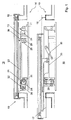
- the window 10 is shown in a side view, wherein the frame 11 is a stationary base member, over which the window frame 12 is guided by a guide frame 13, and between a closed position 14 and an open position 15 is movable and each can take any position.
- the window frame 12 moves to the transition to the open position 15 initially in the vertical direction to a vertical distance 16 to occupy a lateral distance 17 after reaching the vertical distance 16.
- the window 10 can pass from a closed position 14 in an open position 15 to cancel a separation of an inner side 18 of a building, a vehicle or other space from the outside 19 or restore at a rearward movement.
- the guide frame 13 and the technical means are arranged between the window frame 12 and the frame 11 and, in the closed position 14, do not project beyond the window frame 12.
- This movement is caused by an arrangement of a pair of pinions 20, which comprises a first pinion 21 and a second pinion 22.
- the first pinion 21 is driven in relation to the plane of the drawing in the clockwise direction, for example by means of a motor (not shown), so that the second pinion 22 engaged with a rack 23 rotates counterclockwise.
- a pivoting movement 27 of a front bridge 24 is caused, wherein the front bridge 24, the first pinion 21 in a first axis of rotation 25 and the second pinion 22 rotatably mounted in a second axis of rotation 26 receives, and a rotation of second axis of rotation 26 causes about the first axis of rotation 25.
- the drive of the pinion 21, 22 does not initiate a lateral movement of the rack 23 without passing through a lifting movement 30 on a vertical distance 16
- a guide 28 receives a arranged on the rack 23 guide roller 29, which a positive guidance of the rack 23 and thus of the window frame 12th conditioned in the vertical direction.
- the front bridge 24 performs a pivoting movement 27 until the guide roller 29 leaves the guide 28 and is released in the horizontal direction.
- a rear bridge 31 is arranged in the same manner as the front bridge 24, and, like the front bridge 24, pivotally connects the guide frame 13 to the frame 11.
- the pivotal movement 27 is made in the front and rear bridges 24, 31 parallel, whereby also a parallel movement between the guide frame 13 and the window frame 12 and the frame 11 is made possible.
- the guide roller 29 rolls on a running contour 36 of the frame 11, so that connected to the guide frame 13 window frame 12 by the vertical bridges 24, 31 upwards and by the rolling of the guide roller 29 on the running contour 36 after stabilized below and thus positively guided.
- a stop-damper element 32 may additionally be arranged between the frame 11 and the guide frame 13, which z. B.
- the stopper damper element 32 exerts a compressive force between the frame 11 and the guide frame 13, whereby the lifting movement 30 is promoted to reach the vertical distance 16. In the extended state, the stopper damper element 32 has a stop, whereby the extension movement is limited. In a vertical or inclined mounting position of the window 10, the stopper damper element 32 holds the guide frame 13 in the position on the height distance 16, since this would swing down due to its own weight on the bridges 24, 31, in addition, it prevents when retracting the guide frame 13 a Fall into the closed position 14.
- the rack 23 is guided relative to the guide frame 13 in a guide groove 33, wherein a guide roller 34 rolls in the guide groove 33.
- the guide roller 34 is received above the lower guide roller 29 end in the rack 23, wherein the guide groove 33 is formed in the guide frame 13.
- two guide wheels 35 are above the second axis of rotation 26 of the front bridge 24th arranged according to the present embodiment. Below the guide wheels 35, the second pinion 22 with the rack 23 in engagement, wherein the rack 23 by the toothing with the second pinion 22 undergoes a vertical normal force, and therefore advantageously against the two guide wheels 35 is guided.
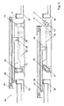
- FIG. 3 shows a window 10 with a modified running contour 36, which has a shoulder, by means of which the pivoting movement 27 of the bridges 24, 31 is made possible beyond a vertical position.
- the window 10 is shown in the upper view in the closed position 14 and in the lower view in a partial open position 15 - in which the required height distance (16) is already present - shown.
- the stop of a possibly installed stop-damper element 32 would have to be extended accordingly in the present embodiment, so that an enlarged pivoting movement 27 is made possible.
- the stroke of the window 10 in its vertical distance 16 can be changed over the horizontal travel path to reach the lateral distance 17, so that the window frame 12 can be lifted, for example, via a closing frame 39.
- the window frame 12 is first raised to a greater vertical distance 16, and after passing over the end frame 39, the window frame 12 sinks again.
- the running contour 36 can be modified as desired in order to adapt the stroke over the lateral extension movement to different installation environments of the window 10.
- Fig. 4 is an illustration of the window 10 is shown in a non-horizontal mounting position, wherein a modified arrangement of the guide 28 is provided for generating a non-linear stroke movement 38.
- the guide 28 is arranged at a helix angle 37, whereby the lifting movement 30 merges into a non-continuous stroke 38.
- the discontinuous lifting movement 38 consists of a plurality of individual linear movement sections, which allow a lateral movement start of the window frame 12 from the closed position 14, so that, for example, a separate frame of the window frame 12 can be released from a groove.
- the separate frame provides privacy and protection from weathering of the internal mechanism by pressing the window frame, for example in the closed position 14, against a sealing element 42 in the end frame 39.
- the window frame 12 is provided with a locking means and the frame 11 with a counter-locking means.
- the locking means in the window frame 12 consists in the present example of a nose-shaped projection which cooperates with a notch or groove as a counter-locking means in the frame 11.
- the contact surfaces of the locking means and the counter-locking means are coordinated.
- a sealing element 42 (not shown in FIG. 4) may be arranged in the region of the latching means or exactly between or on the contact surfaces of the latching means.
- FIG. 5 shows a further exemplary embodiment of the window 10 or window fitting according to the invention.
- this exemplary embodiment additionally has a locking pawl 40.
- This pawl 40 may replace, for example, the already described running contour 36, so that can be dispensed with a forced operation over the entire travel of the window frame 12. This makes it possible to dispense with a complex milled part for the running contour 36.
- the pawl 40 is directed by means of a torsion spring, as soon as the pivotable bridges 24, 31 have reached the pivoting movement 27 for the required height spacing 16 of the window frame 12. As a result, the window frame 12 is held by the pawl 40 at the desired height distance 16. For this purpose, the pawl 40 can engage.
- a (locking) bolt 41 for example on a bridge 24, 31. It is also conceivable that this bolt 41 is arranged on the guide frame 13.
- the guide 28 acts as in the guide already described, but not designed by the use of the pawl 40 over the entire length of the travel of the window frame 12 have to be.
- the pawl 40 is released by an example attached to the end of the rack 23 and the sliding means roller 29 from its locked position, whereby the height distance 16 is changed again.
- the bolt 41 already described pushes in the lowering movement of the window frame 12, the pawl 40 against the force of the torsion spring down.
- the lifting or lowering movement of the window frame 12 can be additionally supported by the illustrated stop-damper element 32, which is configured in the present case as a gas spring.
- the conditional on the size or desired height distance 16 of the window frame 12 can be specified on the one hand by the length of the bridges 24, 31 and on the other hand by the upper and lower end position of the bridge 24, 31.
Landscapes
- Engineering & Computer Science (AREA)
- Mechanical Engineering (AREA)
- Power-Operated Mechanisms For Wings (AREA)
- Window Of Vehicle (AREA)
- Special Wing (AREA)
- Memory System Of A Hierarchy Structure (AREA)
- Wing Frames And Configurations (AREA)
Priority Applications (1)
| Application Number | Priority Date | Filing Date | Title |
|---|---|---|---|
| PL06116471T PL1752602T3 (pl) | 2005-08-12 | 2006-06-30 | Okno z funkcją unoszenia i przesuwania |
Applications Claiming Priority (1)
| Application Number | Priority Date | Filing Date | Title |
|---|---|---|---|
| DE102005038408A DE102005038408A1 (de) | 2005-08-12 | 2005-08-12 | Fenster mit Hubschiebefunktion |
Publications (3)
| Publication Number | Publication Date |
|---|---|
| EP1752602A2 true EP1752602A2 (fr) | 2007-02-14 |
| EP1752602A3 EP1752602A3 (fr) | 2008-01-23 |
| EP1752602B1 EP1752602B1 (fr) | 2011-08-10 |
Family
ID=37441237
Family Applications (1)
| Application Number | Title | Priority Date | Filing Date |
|---|---|---|---|
| EP06116471A Not-in-force EP1752602B1 (fr) | 2005-08-12 | 2006-06-30 | Fenêtre coulissante et soulevable |
Country Status (4)
| Country | Link |
|---|---|
| EP (1) | EP1752602B1 (fr) |
| AT (1) | ATE519910T1 (fr) |
| DE (1) | DE102005038408A1 (fr) |
| PL (1) | PL1752602T3 (fr) |
Cited By (12)
| Publication number | Priority date | Publication date | Assignee | Title |
|---|---|---|---|---|
| EP1961900A1 (fr) | 2007-02-22 | 2008-08-27 | Nordseewerke GmbH | Dispositif de système de portière anti-chocs |
| WO2008101601A1 (fr) * | 2007-02-24 | 2008-08-28 | Daimler Ag | Porte coulissante pour véhicule |
| WO2008145638A1 (fr) * | 2007-05-25 | 2008-12-04 | Klima Delta Gmbh | Garniture de fenêtre comprenant un système d'entraînement à pignon et crémaillère pour déplacer un cadre de fenêtre dans un dormant |
| WO2009024561A1 (fr) * | 2007-08-17 | 2009-02-26 | Rainer Hardt | Fenêtre et ferrure de fenêtre |
| CN101992838A (zh) * | 2009-08-24 | 2011-03-30 | 货运技术芬兰有限公司 | 货船装货舱口的操作机构 |
| CN102619429A (zh) * | 2012-04-10 | 2012-08-01 | 江苏田娘农业科技有限公司 | 一种发酵库大门的自动压紧装置 |
| DE102013218388A1 (de) | 2013-09-13 | 2015-03-19 | Volkswagen Aktiengesellschaft | Fahrzeug mit zumindest einem Fensterausschnitt für eine Fensterscheibe |
| DE102015210564A1 (de) | 2015-06-09 | 2016-12-15 | Volkswagen Aktiengesellschaft | Fahrzeug mit zumindest einem Fensterausschnitt für eine Fensterscheibe |
| CN108086868A (zh) * | 2017-12-29 | 2018-05-29 | 上海都市绿色工程有限公司 | 一种温室湿帘的外垂直窗结构 |
| CN110005310A (zh) * | 2019-03-19 | 2019-07-12 | 孟大军 | 一种设置于墙体或屋顶的开合装置 |
| CN111155866A (zh) * | 2020-01-08 | 2020-05-15 | 温州医科大学 | 一种光感应自动窗户的控制系统及方法 |
| CN112431503A (zh) * | 2020-11-26 | 2021-03-02 | 广东图特家居科技股份有限公司 | 联动机构及平趟门 |
Families Citing this family (2)
| Publication number | Priority date | Publication date | Assignee | Title |
|---|---|---|---|---|
| DE102004016091B4 (de) * | 2003-07-24 | 2016-02-18 | Volkswagen Ag | Vorrichtung zur Führung einer Schiebetür |
| CN105059094B (zh) * | 2015-08-04 | 2018-01-16 | 北京汽车研究总院有限公司 | 一种车门结构及汽车 |
Citations (5)
| Publication number | Priority date | Publication date | Assignee | Title |
|---|---|---|---|---|
| DE3308751A1 (de) | 1982-03-12 | 1983-09-22 | Toyota Auto Body Co Ltd | Tuerbetaetigungsvorrichtung fuer eine schiebetuer |
| EP0103725B1 (fr) | 1982-09-18 | 1988-12-07 | Gretsch-Unitas GmbH Baubeschläge | Ferrure pour un battant de fenêtre, porte ou similaire, qui peut au moins être déplacée dans un plan parallèle |
| DE19634369C1 (de) | 1996-08-26 | 1997-09-18 | Daimler Benz Ag | Vorrichtung zum Führen einer ausschwenkbaren Schiebetür an einer Fahrzeugkarosserie |
| DE19632427A1 (de) | 1996-08-12 | 1998-02-19 | Webasto Tuersysteme Gmbh | Schwenkschiebetür für Fahrzeuge |
| DE102004016091A1 (de) | 2003-07-24 | 2005-03-03 | Volkswagen Ag | Vorrichtung zur Führung einer Schiebetür |
Family Cites Families (2)
| Publication number | Priority date | Publication date | Assignee | Title |
|---|---|---|---|---|
| FR2278893A1 (fr) * | 1974-07-18 | 1976-02-13 | Faiveley Sa | Porte a mouvement louvoyant |
| FR2387343A2 (fr) * | 1977-04-13 | 1978-11-10 | Faiveley Sa | Porte a mouvement louvoyant |
-
2005
- 2005-08-12 DE DE102005038408A patent/DE102005038408A1/de not_active Withdrawn
-
2006
- 2006-06-30 EP EP06116471A patent/EP1752602B1/fr not_active Not-in-force
- 2006-06-30 AT AT06116471T patent/ATE519910T1/de active
- 2006-06-30 PL PL06116471T patent/PL1752602T3/pl unknown
Patent Citations (5)
| Publication number | Priority date | Publication date | Assignee | Title |
|---|---|---|---|---|
| DE3308751A1 (de) | 1982-03-12 | 1983-09-22 | Toyota Auto Body Co Ltd | Tuerbetaetigungsvorrichtung fuer eine schiebetuer |
| EP0103725B1 (fr) | 1982-09-18 | 1988-12-07 | Gretsch-Unitas GmbH Baubeschläge | Ferrure pour un battant de fenêtre, porte ou similaire, qui peut au moins être déplacée dans un plan parallèle |
| DE19632427A1 (de) | 1996-08-12 | 1998-02-19 | Webasto Tuersysteme Gmbh | Schwenkschiebetür für Fahrzeuge |
| DE19634369C1 (de) | 1996-08-26 | 1997-09-18 | Daimler Benz Ag | Vorrichtung zum Führen einer ausschwenkbaren Schiebetür an einer Fahrzeugkarosserie |
| DE102004016091A1 (de) | 2003-07-24 | 2005-03-03 | Volkswagen Ag | Vorrichtung zur Führung einer Schiebetür |
Cited By (14)
| Publication number | Priority date | Publication date | Assignee | Title |
|---|---|---|---|---|
| EP1961900A1 (fr) | 2007-02-22 | 2008-08-27 | Nordseewerke GmbH | Dispositif de système de portière anti-chocs |
| WO2008101601A1 (fr) * | 2007-02-24 | 2008-08-28 | Daimler Ag | Porte coulissante pour véhicule |
| WO2008145638A1 (fr) * | 2007-05-25 | 2008-12-04 | Klima Delta Gmbh | Garniture de fenêtre comprenant un système d'entraînement à pignon et crémaillère pour déplacer un cadre de fenêtre dans un dormant |
| WO2009024561A1 (fr) * | 2007-08-17 | 2009-02-26 | Rainer Hardt | Fenêtre et ferrure de fenêtre |
| CN101992838B (zh) * | 2009-08-24 | 2015-01-14 | 货运技术芬兰有限公司 | 货船装货舱口的操作机构 |
| CN101992838A (zh) * | 2009-08-24 | 2011-03-30 | 货运技术芬兰有限公司 | 货船装货舱口的操作机构 |
| CN102619429A (zh) * | 2012-04-10 | 2012-08-01 | 江苏田娘农业科技有限公司 | 一种发酵库大门的自动压紧装置 |
| DE102013218388A1 (de) | 2013-09-13 | 2015-03-19 | Volkswagen Aktiengesellschaft | Fahrzeug mit zumindest einem Fensterausschnitt für eine Fensterscheibe |
| DE102015210564A1 (de) | 2015-06-09 | 2016-12-15 | Volkswagen Aktiengesellschaft | Fahrzeug mit zumindest einem Fensterausschnitt für eine Fensterscheibe |
| CN108086868A (zh) * | 2017-12-29 | 2018-05-29 | 上海都市绿色工程有限公司 | 一种温室湿帘的外垂直窗结构 |
| CN108086868B (zh) * | 2017-12-29 | 2024-05-17 | 上海都市绿色工程有限公司 | 一种温室湿帘的外垂直窗结构 |
| CN110005310A (zh) * | 2019-03-19 | 2019-07-12 | 孟大军 | 一种设置于墙体或屋顶的开合装置 |
| CN111155866A (zh) * | 2020-01-08 | 2020-05-15 | 温州医科大学 | 一种光感应自动窗户的控制系统及方法 |
| CN112431503A (zh) * | 2020-11-26 | 2021-03-02 | 广东图特家居科技股份有限公司 | 联动机构及平趟门 |
Also Published As
| Publication number | Publication date |
|---|---|
| EP1752602B1 (fr) | 2011-08-10 |
| PL1752602T3 (pl) | 2012-01-31 |
| DE102005038408A1 (de) | 2007-02-15 |
| ATE519910T1 (de) | 2011-08-15 |
| EP1752602A3 (fr) | 2008-01-23 |
Similar Documents
| Publication | Publication Date | Title |
|---|---|---|
| EP1752602B1 (fr) | Fenêtre coulissante et soulevable | |
| EP1767427B1 (fr) | Dispositif pour le mouvement d'un vantail de porte d'une porte pivotante coulissante, notamment pour véhicules ferroviaires | |
| AT500017B1 (de) | Schwenkschiebetür für fahrzeuge | |
| EP1568563B1 (fr) | Dispositif de verrouillage d'une porte coulissante et pivotante pour véhicules pour le transport de personnes, notamment véhicules de transport urbain de personnes | |
| EP1559861B1 (fr) | Fenêtre | |
| EP1314626A1 (fr) | Porte coulissante et pivotante pour véhicules, notamment porte des passagers pour véhicules de transport urbain de personnes | |
| DE4437250A1 (de) | Einrichtung für die Ausführung des Schließ- und Öffnungsvorganges eines Kippfensters | |
| DE102007054694A1 (de) | Rolloanordnung mit verminderter Reibung in den Antriebsgabeln | |
| EP1584535A1 (fr) | Porte pivotante coulissante pour voitures ferroviaires | |
| EP1813759B1 (fr) | Dispositif pour déplacer une porte coulissante-pivotante de vehicule | |
| DE9418079U1 (de) | Freitragendes Schiebetor | |
| DE19718091A1 (de) | Vorrichtung zum Öffnen/Schließen eines Fahrzeugfensters | |
| DE2507893C3 (de) | Fensterheber für vertikal unterteilte Kraftfahrzeugschiebefenster | |
| WO1988000892A1 (fr) | Porte coulissante pour vehicules a moteur, notamment des voitures particulieres | |
| DE202005007984U1 (de) | Schiebetür oder Schwenkschiebetür für Fahrzeuge des öffentlichen Personennah- und -fernverkehrs | |
| DE102004016091B4 (de) | Vorrichtung zur Führung einer Schiebetür | |
| DE4331078A1 (de) | Vorrichtung zur Bewegung einer Schwenkschiebetür für Fahrzeuge zur Personenbeförderung, insbesondere Schienenfahrzeuge | |
| EP2181232A1 (fr) | Fenêtre et ferrure de fenêtre | |
| EP0905343B1 (fr) | Agencement de fenêtre ou de porte | |
| EP1522666B1 (fr) | Ferrure pour portes ou fenêtres à soulèvement et coulissement et chariot pour un tel ferrure. | |
| DE2839797A1 (de) | Fenster mit einem kippbaren und horizontal verschiebbaren fluegel | |
| DE202005007983U1 (de) | Schiebetür oder Schwenkschiebetür für Fahrzeuge des öffentlichen Personennah- und -fernverkehrs | |
| AT401082B (de) | Ein- oder zweiflügelige schiebe-, schwenkschiebe- oder taschentür | |
| DE3425810C2 (fr) | ||
| EP0930416B1 (fr) | Volet roulant |
Legal Events
| Date | Code | Title | Description |
|---|---|---|---|
| PUAI | Public reference made under article 153(3) epc to a published international application that has entered the european phase |
Free format text: ORIGINAL CODE: 0009012 |
|
| AK | Designated contracting states |
Kind code of ref document: A2 Designated state(s): AT BE BG CH CY CZ DE DK EE ES FI FR GB GR HU IE IS IT LI LT LU LV MC NL PL PT RO SE SI SK TR |
|
| AX | Request for extension of the european patent |
Extension state: AL BA HR MK YU |
|
| PUAL | Search report despatched |
Free format text: ORIGINAL CODE: 0009013 |
|
| AK | Designated contracting states |
Kind code of ref document: A3 Designated state(s): AT BE BG CH CY CZ DE DK EE ES FI FR GB GR HU IE IS IT LI LT LU LV MC NL PL PT RO SE SI SK TR |
|
| AX | Request for extension of the european patent |
Extension state: AL BA HR MK YU |
|
| RIC1 | Information provided on ipc code assigned before grant |
Ipc: E05D 15/10 20060101AFI20061201BHEP Ipc: E05F 15/14 20060101ALI20071219BHEP |
|
| 17P | Request for examination filed |
Effective date: 20080723 |
|
| 17Q | First examination report despatched |
Effective date: 20080821 |
|
| AKX | Designation fees paid |
Designated state(s): AT BE BG CH CY CZ DE DK EE ES FI FR GB GR HU IE IS IT LI LT LU LV MC NL PL PT RO SE SI SK TR |
|
| AXX | Extension fees paid |
Extension state: HR Payment date: 20080723 Extension state: BA Payment date: 20080723 Extension state: MK Payment date: 20080723 Extension state: AL Payment date: 20080723 |
|
| RAX | Requested extension states of the european patent have changed |
Extension state: AL Payment date: 20080723 Extension state: RS Payment date: 20080723 Extension state: HR Payment date: 20080723 Extension state: BA Payment date: 20080723 Extension state: MK Payment date: 20080723 |
|
| DAX | Request for extension of the european patent (deleted) | ||
| RAP1 | Party data changed (applicant data changed or rights of an application transferred) |
Owner name: HARDT, RAINER |
|
| RIN1 | Information on inventor provided before grant (corrected) |
Inventor name: HEUCHEMER, KLAUS Inventor name: HARDT, RAINER |
|
| GRAP | Despatch of communication of intention to grant a patent |
Free format text: ORIGINAL CODE: EPIDOSNIGR1 |
|
| GRAS | Grant fee paid |
Free format text: ORIGINAL CODE: EPIDOSNIGR3 |
|
| GRAA | (expected) grant |
Free format text: ORIGINAL CODE: 0009210 |
|
| AK | Designated contracting states |
Kind code of ref document: B1 Designated state(s): AT BE BG CH CY CZ DE DK EE ES FI FR GB GR HU IE IS IT LI LT LU LV MC NL PL PT RO SE SI SK TR |
|
| REG | Reference to a national code |
Ref country code: GB Ref legal event code: FG4D Free format text: NOT ENGLISH |
|
| REG | Reference to a national code |
Ref country code: CH Ref legal event code: EP |
|
| REG | Reference to a national code |
Ref country code: IE Ref legal event code: FG4D Free format text: LANGUAGE OF EP DOCUMENT: GERMAN |
|
| REG | Reference to a national code |
Ref country code: DE Ref legal event code: R096 Ref document number: 502006009995 Country of ref document: DE Effective date: 20111006 |
|
| REG | Reference to a national code |
Ref country code: NL Ref legal event code: T3 |
|
| REG | Reference to a national code |
Ref country code: DE Ref legal event code: R083 Ref document number: 502006009995 Country of ref document: DE |
|
| LTIE | Lt: invalidation of european patent or patent extension |
Effective date: 20110810 |
|
| PG25 | Lapsed in a contracting state [announced via postgrant information from national office to epo] |
Ref country code: SE Free format text: LAPSE BECAUSE OF FAILURE TO SUBMIT A TRANSLATION OF THE DESCRIPTION OR TO PAY THE FEE WITHIN THE PRESCRIBED TIME-LIMIT Effective date: 20110810 Ref country code: IS Free format text: LAPSE BECAUSE OF FAILURE TO SUBMIT A TRANSLATION OF THE DESCRIPTION OR TO PAY THE FEE WITHIN THE PRESCRIBED TIME-LIMIT Effective date: 20111210 Ref country code: PT Free format text: LAPSE BECAUSE OF FAILURE TO SUBMIT A TRANSLATION OF THE DESCRIPTION OR TO PAY THE FEE WITHIN THE PRESCRIBED TIME-LIMIT Effective date: 20111212 Ref country code: FI Free format text: LAPSE BECAUSE OF FAILURE TO SUBMIT A TRANSLATION OF THE DESCRIPTION OR TO PAY THE FEE WITHIN THE PRESCRIBED TIME-LIMIT Effective date: 20110810 Ref country code: LT Free format text: LAPSE BECAUSE OF FAILURE TO SUBMIT A TRANSLATION OF THE DESCRIPTION OR TO PAY THE FEE WITHIN THE PRESCRIBED TIME-LIMIT Effective date: 20110810 |
|
| REG | Reference to a national code |
Ref country code: PL Ref legal event code: T3 Ref country code: DE Ref legal event code: R082 Ref document number: 502006009995 Country of ref document: DE Representative=s name: JOCHEN MUELLER, DE Ref country code: DE Ref legal event code: R082 Ref document number: 502006009995 Country of ref document: DE Representative=s name: MUELLER, JOCHEN, DIPL.-ING., DE |
|
| PG25 | Lapsed in a contracting state [announced via postgrant information from national office to epo] |
Ref country code: SI Free format text: LAPSE BECAUSE OF FAILURE TO SUBMIT A TRANSLATION OF THE DESCRIPTION OR TO PAY THE FEE WITHIN THE PRESCRIBED TIME-LIMIT Effective date: 20110810 Ref country code: LV Free format text: LAPSE BECAUSE OF FAILURE TO SUBMIT A TRANSLATION OF THE DESCRIPTION OR TO PAY THE FEE WITHIN THE PRESCRIBED TIME-LIMIT Effective date: 20110810 Ref country code: CY Free format text: LAPSE BECAUSE OF FAILURE TO SUBMIT A TRANSLATION OF THE DESCRIPTION OR TO PAY THE FEE WITHIN THE PRESCRIBED TIME-LIMIT Effective date: 20110810 Ref country code: GR Free format text: LAPSE BECAUSE OF FAILURE TO SUBMIT A TRANSLATION OF THE DESCRIPTION OR TO PAY THE FEE WITHIN THE PRESCRIBED TIME-LIMIT Effective date: 20111111 |
|
| REG | Reference to a national code |
Ref country code: IE Ref legal event code: FD4D |
|
| PG25 | Lapsed in a contracting state [announced via postgrant information from national office to epo] |
Ref country code: CZ Free format text: LAPSE BECAUSE OF FAILURE TO SUBMIT A TRANSLATION OF THE DESCRIPTION OR TO PAY THE FEE WITHIN THE PRESCRIBED TIME-LIMIT Effective date: 20110810 Ref country code: IE Free format text: LAPSE BECAUSE OF FAILURE TO SUBMIT A TRANSLATION OF THE DESCRIPTION OR TO PAY THE FEE WITHIN THE PRESCRIBED TIME-LIMIT Effective date: 20110810 Ref country code: SK Free format text: LAPSE BECAUSE OF FAILURE TO SUBMIT A TRANSLATION OF THE DESCRIPTION OR TO PAY THE FEE WITHIN THE PRESCRIBED TIME-LIMIT Effective date: 20110810 |
|
| PG25 | Lapsed in a contracting state [announced via postgrant information from national office to epo] |
Ref country code: EE Free format text: LAPSE BECAUSE OF FAILURE TO SUBMIT A TRANSLATION OF THE DESCRIPTION OR TO PAY THE FEE WITHIN THE PRESCRIBED TIME-LIMIT Effective date: 20110810 Ref country code: IT Free format text: LAPSE BECAUSE OF FAILURE TO SUBMIT A TRANSLATION OF THE DESCRIPTION OR TO PAY THE FEE WITHIN THE PRESCRIBED TIME-LIMIT Effective date: 20110810 Ref country code: RO Free format text: LAPSE BECAUSE OF FAILURE TO SUBMIT A TRANSLATION OF THE DESCRIPTION OR TO PAY THE FEE WITHIN THE PRESCRIBED TIME-LIMIT Effective date: 20110810 |
|
| PLBE | No opposition filed within time limit |
Free format text: ORIGINAL CODE: 0009261 |
|
| STAA | Information on the status of an ep patent application or granted ep patent |
Free format text: STATUS: NO OPPOSITION FILED WITHIN TIME LIMIT |
|
| PG25 | Lapsed in a contracting state [announced via postgrant information from national office to epo] |
Ref country code: DK Free format text: LAPSE BECAUSE OF FAILURE TO SUBMIT A TRANSLATION OF THE DESCRIPTION OR TO PAY THE FEE WITHIN THE PRESCRIBED TIME-LIMIT Effective date: 20110810 |
|
| 26N | No opposition filed |
Effective date: 20120511 |
|
| REG | Reference to a national code |
Ref country code: DE Ref legal event code: R097 Ref document number: 502006009995 Country of ref document: DE Effective date: 20120511 |
|
| PG25 | Lapsed in a contracting state [announced via postgrant information from national office to epo] |
Ref country code: MC Free format text: LAPSE BECAUSE OF NON-PAYMENT OF DUE FEES Effective date: 20120630 |
|
| PGFP | Annual fee paid to national office [announced via postgrant information from national office to epo] |
Ref country code: AT Payment date: 20120620 Year of fee payment: 7 |
|
| PG25 | Lapsed in a contracting state [announced via postgrant information from national office to epo] |
Ref country code: ES Free format text: LAPSE BECAUSE OF FAILURE TO SUBMIT A TRANSLATION OF THE DESCRIPTION OR TO PAY THE FEE WITHIN THE PRESCRIBED TIME-LIMIT Effective date: 20111121 |
|
| PG25 | Lapsed in a contracting state [announced via postgrant information from national office to epo] |
Ref country code: BG Free format text: LAPSE BECAUSE OF FAILURE TO SUBMIT A TRANSLATION OF THE DESCRIPTION OR TO PAY THE FEE WITHIN THE PRESCRIBED TIME-LIMIT Effective date: 20111110 |
|
| PGFP | Annual fee paid to national office [announced via postgrant information from national office to epo] |
Ref country code: GB Payment date: 20130620 Year of fee payment: 8 Ref country code: CH Payment date: 20130621 Year of fee payment: 8 |
|
| PGFP | Annual fee paid to national office [announced via postgrant information from national office to epo] |
Ref country code: TR Payment date: 20130620 Year of fee payment: 8 Ref country code: PL Payment date: 20130619 Year of fee payment: 8 |
|
| PG25 | Lapsed in a contracting state [announced via postgrant information from national office to epo] |
Ref country code: LU Free format text: LAPSE BECAUSE OF NON-PAYMENT OF DUE FEES Effective date: 20120630 |
|
| PG25 | Lapsed in a contracting state [announced via postgrant information from national office to epo] |
Ref country code: HU Free format text: LAPSE BECAUSE OF FAILURE TO SUBMIT A TRANSLATION OF THE DESCRIPTION OR TO PAY THE FEE WITHIN THE PRESCRIBED TIME-LIMIT Effective date: 20060630 |
|
| PGFP | Annual fee paid to national office [announced via postgrant information from national office to epo] |
Ref country code: BE Payment date: 20140630 Year of fee payment: 9 Ref country code: NL Payment date: 20140626 Year of fee payment: 9 |
|
| PGFP | Annual fee paid to national office [announced via postgrant information from national office to epo] |
Ref country code: FR Payment date: 20140626 Year of fee payment: 9 |
|
| REG | Reference to a national code |
Ref country code: CH Ref legal event code: PL |
|
| REG | Reference to a national code |
Ref country code: AT Ref legal event code: MM01 Ref document number: 519910 Country of ref document: AT Kind code of ref document: T Effective date: 20140630 |
|
| GBPC | Gb: european patent ceased through non-payment of renewal fee |
Effective date: 20140630 |
|
| PG25 | Lapsed in a contracting state [announced via postgrant information from national office to epo] |
Ref country code: LI Free format text: LAPSE BECAUSE OF NON-PAYMENT OF DUE FEES Effective date: 20140630 Ref country code: CH Free format text: LAPSE BECAUSE OF NON-PAYMENT OF DUE FEES Effective date: 20140630 |
|
| PG25 | Lapsed in a contracting state [announced via postgrant information from national office to epo] |
Ref country code: AT Free format text: LAPSE BECAUSE OF NON-PAYMENT OF DUE FEES Effective date: 20140630 Ref country code: GB Free format text: LAPSE BECAUSE OF NON-PAYMENT OF DUE FEES Effective date: 20140630 |
|
| REG | Reference to a national code |
Ref country code: PL Ref legal event code: LAPE |
|
| PG25 | Lapsed in a contracting state [announced via postgrant information from national office to epo] |
Ref country code: PL Free format text: LAPSE BECAUSE OF NON-PAYMENT OF DUE FEES Effective date: 20140630 |
|
| REG | Reference to a national code |
Ref country code: NL Ref legal event code: MM Effective date: 20150701 |
|
| REG | Reference to a national code |
Ref country code: FR Ref legal event code: ST Effective date: 20160229 |
|
| PG25 | Lapsed in a contracting state [announced via postgrant information from national office to epo] |
Ref country code: NL Free format text: LAPSE BECAUSE OF NON-PAYMENT OF DUE FEES Effective date: 20150701 |
|
| PG25 | Lapsed in a contracting state [announced via postgrant information from national office to epo] |
Ref country code: FR Free format text: LAPSE BECAUSE OF NON-PAYMENT OF DUE FEES Effective date: 20150630 |
|
| REG | Reference to a national code |
Ref country code: DE Ref legal event code: R084 Ref document number: 502006009995 Country of ref document: DE |
|
| PGFP | Annual fee paid to national office [announced via postgrant information from national office to epo] |
Ref country code: DE Payment date: 20160627 Year of fee payment: 11 |
|
| PG25 | Lapsed in a contracting state [announced via postgrant information from national office to epo] |
Ref country code: BE Free format text: LAPSE BECAUSE OF NON-PAYMENT OF DUE FEES Effective date: 20150630 |
|
| PG25 | Lapsed in a contracting state [announced via postgrant information from national office to epo] |
Ref country code: TR Free format text: LAPSE BECAUSE OF NON-PAYMENT OF DUE FEES Effective date: 20140630 |
|
| REG | Reference to a national code |
Ref country code: DE Ref legal event code: R119 Ref document number: 502006009995 Country of ref document: DE |
|
| PG25 | Lapsed in a contracting state [announced via postgrant information from national office to epo] |
Ref country code: DE Free format text: LAPSE BECAUSE OF NON-PAYMENT OF DUE FEES Effective date: 20180103 |