EP1752248B1 - Arc welding device control method and arc welding device - Google Patents
Arc welding device control method and arc welding device Download PDFInfo
- Publication number
- EP1752248B1 EP1752248B1 EP05814756A EP05814756A EP1752248B1 EP 1752248 B1 EP1752248 B1 EP 1752248B1 EP 05814756 A EP05814756 A EP 05814756A EP 05814756 A EP05814756 A EP 05814756A EP 1752248 B1 EP1752248 B1 EP 1752248B1
- Authority
- EP
- European Patent Office
- Prior art keywords
- welding
- neck
- voltage
- detection
- threshold
- Prior art date
- Legal status (The legal status is an assumption and is not a legal conclusion. Google has not performed a legal analysis and makes no representation as to the accuracy of the status listed.)
- Expired - Lifetime
Links
Images


Classifications
-
- B—PERFORMING OPERATIONS; TRANSPORTING
- B23—MACHINE TOOLS; METAL-WORKING NOT OTHERWISE PROVIDED FOR
- B23K—SOLDERING OR UNSOLDERING; WELDING; CLADDING OR PLATING BY SOLDERING OR WELDING; CUTTING BY APPLYING HEAT LOCALLY, e.g. FLAME CUTTING; WORKING BY LASER BEAM
- B23K9/00—Arc welding or cutting
- B23K9/095—Monitoring or automatic control of welding parameters
- B23K9/0953—Monitoring or automatic control of welding parameters using computing means
-
- B—PERFORMING OPERATIONS; TRANSPORTING
- B23—MACHINE TOOLS; METAL-WORKING NOT OTHERWISE PROVIDED FOR
- B23K—SOLDERING OR UNSOLDERING; WELDING; CLADDING OR PLATING BY SOLDERING OR WELDING; CUTTING BY APPLYING HEAT LOCALLY, e.g. FLAME CUTTING; WORKING BY LASER BEAM
- B23K9/00—Arc welding or cutting
- B23K9/06—Arrangements or circuits for starting the arc, e.g. by generating ignition voltage, or for stabilising the arc
- B23K9/073—Stabilising the arc
- B23K9/0731—Stabilising of the arc tension
Definitions
- the present invention relates to a control method for an arc welding apparatus and an arc welding apparatus.
- Arc welding carries out welding by generating arc between a welding wire and a welding base material.
- a consumable electrode type arc welding apparatus (hereinafter, referred to as "a welding apparatus") predicts that a short circuit is opened and reduces welding current just before short circuit is opened in order to suppress the generation of spatter. This is a so-called neck detection control. Then, arc force is suppressed by reducing welding current at the moment at which arc is generated again.
- a control circuit for controlling a welding output increases an electric current in accordance with a predetermined tilt in order to open the short circuit. Then, in accordance with this increase of electric current, a wire in a short-circuit part is melted and the molten metal is shifted to the side of a base material, so that a constricted portion (a so-called neck, which is referred to as “neck,” hereinafter) is formed between the welding wire and the molten portion at the side of the base material. Since the cross-sectional area at this neck portion becomes small, the resistance value is increased. Therefore, when neck is formed, although the increase of electric current is kept constant by short-circuit control, a change amount of welding voltage is increased. Then, by detecting the change amount of voltage, the formation of neck is detected, and the process is proceeded to neck detection control.
- a conventional welding apparatus is provided with a switching element for switching rectified AC power supply in order to obtain an output suitable for welding as mentioned below. Then, under the effect of this switching element, ripple voltage synchronous with switching of the switching element is superimposed on the welding voltage. This ripple voltage may lower the neck detection probability. Therefore, Japanese Patent Unexamined Publication No. H10-180443 discloses removal of noise such as ripple voltage.
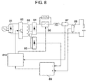
- Fig. 8 shows a schematic configuration of a conventional welding apparatus.
- the welding apparatus includes first rectifying element 81 for rectifying AC power supply, first switching element 82 for switching the output from first rectifying element 81, main transformer 83 supplying welding load with electric power and being provided with secondary side auxiliary winding, second rectifying element 84 for rectifying the output from main transformer 83, third rectifying element 85 for rectifying the output from the auxiliary winding of main transformer 83, second switching element 86 provided between second rectifying element 84 and an output terminal, current detector 87, voltage detector 88, differential amplifier circuit 89 for operating the difference between the output from voltage detector 88 and the output from third rectifying element 85, and welding control circuit 810 for controlling a welding output by controlling first switching element 82 and second switching element 86.
- Electric power supplied from an AC power supply is made into a direct current by first rectifying element 81.
- the direct current electric power is input into main transformer 83 as necessary electric power in accordance with a welding state by first switching element 82.
- a large current obtained from the output side of main transformer 83 is made into a direct current by second rectifying element 84, and supplied as an electric power to a welding load through second switching element 86.
- Welding current flowing to the welding load is detected by current detector 87 and fed back to the control circuit.
- welding voltage applied to the welding load is detected by voltage detector 88.
- the welding voltage detected by voltage detector 88 includes a ripple component generated by first switching element 82.
- the output from third rectifying element 85 includes a ripple component by first switching element 82.
- the difference between the output from third rectifying element 85 and the output from voltage detector 88 is operated by differential amplifier circuit 89, and thereby the ripple component included in the welding voltage can be removed.
- welding voltage from which the ripple component has been removed is input into welding control circuit 810 and used for accurate detection of a neck portion or control of welding output.
- a conventional welding apparatus can carry out control and the like of the welding output by removing the effect of a ripple component by a switching element constituting a welding apparatus itself.
- the noises caused by the influence of the other equipment include, for example, as shown in Fig. 9 , noise caused by a switching operation for output control of one welding apparatus 1 and generated in welding voltage of the other welding apparatus 2 when weldings are carried out with respect to the same work by a plurality of welding apparatuses.
- references A, B and C indicate noises of voltage waveform of welding apparatus 2 caused by the switching operation of welding apparatus 1.
- references D, E and F indicate noises of voltage waveform of welding apparatus 1 by the switching operation of welding apparatus 2. Then, in a case where noise cannot be removed, wrong detection of neck occurs. As a result, due to this wrong detection of neck, since detection control is carried out with respect to a neck that is not a neck by nature, it has been difficult to suppress the occurrence of spatter or to obtain an excellent welding result. Furthermore, depending upon the conditions such as noise, opening of short circuit may be detected wrongly.
- the present invention aims to provide a control method for an arc welding apparatus and an arc welding apparatus that enable an accurate neck determination and avoid false neck determination caused by noise.
- Fig. 1 is a block diagram showing a schematic configuration of an arc welding apparatus (hereinafter, referred to as "a welding apparatus") in this exemplary embodiment.
- the welding apparatus includes AC power supply 1 for supplying electric power, first rectifying element 2 for rectifying the output from AC power supply 1, first switching element 3 for switching the output from first rectifying element 2 in order to obtain an output suitable for welding; main transformer 4 for supplying welding load with electric power; second rectifying element 5 for rectifying the output from main transformer 4, second switching element 6 with one end coupled to second rectifying element 5, resistor 7 coupled in parallel to second switching element 6, reactor 8 coupled in series to second switching element 6 and stabilizing the output of welding current, current detector 9 for detecting the output amount of welding current, and voltage detector 10 for detecting welding voltage.
- AC power supply 1 for supplying electric power
- first rectifying element 2 for rectifying the output from AC power supply 1
- first switching element 3 for switching the output from first rectifying element 2 in order to obtain an output suitable for welding
- main transformer 4 for supplying welding load with electric power
- neck detection apparatus 19 for detecting the formation of a constricted portion (hereinafter, referred to as "neck”) formed in a welding wire portion at the time of welding includes voltage change amount detection part 11 for calculating the change amount of voltage based on the output from voltage detector 10, neck determination part 12 for determining the detection of neck formed when a short-circuit state is shifted to an arc state during welding based on the output from voltage change amount detection part 11, and neck detection prohibiting part 13 for prohibiting determination processing of neck determination part 12.
- a droplet means a drop of metal that has been melted from the tip of a welding wire to be shifted to a base material.
- arc / short-circuit determination part (hereinafter, "A/S determination part") 14 detects whether an arc state or a short-circuit state in a welding state based on the output from voltage detector 10.
- Welding control apparatus 20 includes welding output control part 15, control state storage part 16 and timer part 17.
- Welding output control part 15 controls the welding output by controlling first switching element 3 and second switching element 6 based on the outputs from current detector 9, voltage detector 10, neck detection apparatus 19 and A/S determination part 14.
- Control state storage part 16 stores the welding control state of welding output control part 15 temporarily.
- Timer part 17 measures the time based on a command from welding output control part 15. An operation of the arc welding apparatus configured as mentioned above is described.
- Electric power supplied from AC power supply 1 is made into direct current by first rectifying element 2 and supplied to first switching element 3 as direct current power supply.
- First switching element 3 is on/off controlled by welding output control part 15, which controls the electric power to be supplied to main transformer 4. Then, electric power supplied to main transformer 4 is made into direct current by second rectifying element 5 and supplied to a welding load.
- second switching element 6 is in an ON state and welding current is supplied to a welding load through reactor 8.
- welding output control part 15 turns off second switching element 6 to block a path through which welding current with low impedance is supplied. Then, energy stored in main transformer 4 is consumed through resistor 7 coupled in parallel to second switching element 6.
- current detector 9 detects welding current supplied to the welding load and outputs it as welding current Ia.
- Voltage detector 10 detects welding voltage applied to the welding load and outputs it as welding voltage Va.
- A/S determination part 14 is described with reference to Fig. 2 .
- Fig. 2 shows waveforms of welding current (Ia) and welding voltage (Va) at the time of short circuit welding.
- A/S determination part 14 compares welding voltage Va detected by voltage detector 10 with short-circuit determination level Vs0 set for determining the short circuit and stored in a storage part (not shown). Then, when Va becomes not more than Vs0 (reference T1 in Fig. 2 ), A/S determination part 14 determines that welding becomes a short-circuit state and outputs an A/S signal showing a short-circuit state.
- welding output control part 15 receives the A/S signal showing a short-circuit state from A/S determination part 14, it turns off second switching element 6 (t1 in Fig. 2 ).
- welding output control part 15 turns on the second switching element (t2 in Fig. 2 ) so that an electric current can be increased from short-circuit initial current Is0 by a predetermined amount of increase and controls short-circuit electric current for carrying out smooth opening of short circuit by controlling first switching element 3.
- A/S determination part 14 determines that the welding state is a short-circuit state and thereafter, compares welding voltage Va with short-circuit opening determination level Varc set for determining that a short circuit is opened and stored in a storage part (not shown). Then, when Va becomes not less than Varc (T2 in Fig. 2 ), A/S determination part 14 determines that the welding state becomes an arc state and outputs an A/S signal showing an arc state.
- neck detection operation of neck detection apparatus 19 is described with reference to Fig. 3.
- Fig. 3 is a graph showing waveforms of welding current (Ia), welding voltage (Va), and welding voltage change amount (dv/dt) at the time of short circuit welding.
- Voltage change amount detection part 11 constituting neck detection apparatus 19 detects change amount dv/dt of welding voltage Va per predetermined time.
- neck determination part 12 compares voltage change amount dv/dt that is the output from voltage change amount detection part 11 with neck detection level value dVn that has been previously set in a storage part (not shown). Then, in a case where voltage change amount dv/dt is larger than neck detection level value dVn and the below-mentioned neck detection prohibiting part 13 does not prohibit the neck detection, it is determined that the neck is formed and outputs neck detection signal Sn showing the formation of neck (T3 in Fig. 3 ).
- t3 in Fig. 3 indicates the detection of neck.
- t4 and t5 in Fig. 3 indicate that the second switching element is turned off and that the second switching element is turned on, respectively.
- Reference Z indicates a neck detection operation range.
- neck detection prohibiting part 13 prevents wrong detection of neck, which is a point in this exemplary embodiment.
- Fig. 4 is a graph showing waveforms of welding current (Ia), welding voltage (Va) and welding voltage change amount (dv/dt) and a state of A/S signal at the time of short circuit welding.
- Fig. 4 shows an example in which the waveform of welding voltage Va is changed like a wave in part due to noise or disturbance.
- the factor of this change includes noise generated inside a welding apparatus, or noise or disturbance from the outside equipment.
- it may include a case where noise is generated in the welding voltage of the welding apparatus in accordance with this exemplary embodiment due to a switching operation and the like for output control in the other welding apparatus, when weldings are carried out with respect to the same welding member by using the welding apparatus shown in this exemplary embodiment and other welding apparatuses.
- Neck detection prohibiting part 13 inputs this output from voltage change amount detection part 11 and compares it with dVe (negative threshold value). Note here that a comparison part is included in neck detection prohibiting part 13.
- a neck detection prohibition signal is output to neck determination part 12 so as to prohibit the neck determination by neck determination part 12.
- a method for prohibiting the neck determination may include a method of not carrying out the comparison between dv/dt and dVn at neck determination part 12 for a predetermined time, and a method of comparing but not outputting neck detection signal Sn even when dv/dt is larger than dVn.
- timing when neck detection prohibiting part 13 outputs a neck detection prohibition signal was a point of time when dv/dt is smaller than dVe (negative threshold value). However, the timing may be a point of time when dv/dt is smaller than dVe and then becomes larger than dVe. Then, for a predetermined time after this point, the neck detection prohibition signal may be output.
- the predetermined time for prohibiting the neck detection may be set with switching time, etc. of the switching element etc., which is a factor of noise, taken into consideration, or may be decided based on experiment, etc.
- neck detection prohibiting part 13 compares neck detection with dv/dt and dVe by neck detection prohibiting part 13 and neck detection may be prohibited for a predetermined time from the point of time when dv/dt is smaller than dVe or at the point of time when dv/dt is larger than dVe.
- t6 in Fig. 4 indicates the detection of neck.
- Reference Z in Fig. 4 indicates a neck detection operating range.
- a voltage change which increases, then reduces and is back to the ordinary state, is a convex-shaped change although not specifically shown in Fig. 5 .
- FIG. 5 is a graph showing waveforms of welding current (Ia) and welding voltage (Va) by the neck detection control when neck is detected.
- welding output control part 15 receives neck detection signal Sn from neck determination part 12, it reduces welding current Ia to In0 by turning second switching element 6 off so that welding current Ia becomes predetermined neck control current In0 quickly. Thereafter, welding output control part 15 turns on second switching element 6 and controls first switching element 3 so that welding current Ia becomes In0 for a predetermined time or until the welding state becomes an arc state and waits for the determination output from A/S determination part 14 that the welding state becomes an arc state.
- welding output control part 15 allows control state storage part 16 to store a control state (for example, current value, increased amount of electric current, and an elapsed time from the time short circuit is started, and the like) at the point of time when neck is detected (t7 in Fig. 5 ), and outputs a command requiring to start measurement to timer part 17 so as to allow timer part 17 to start measurement of time.
- welding output control part 15 receives an A/S signal showing an arc state from A/S determination part 14 in predetermined time Tn measured by timer part 17, welding output control at the arc time is carried out so as to keep an arc length appropriate (control having a waveform shown by a solid line in Fig. 5 ).
- a processing after timer part 17 is allowed to start measurement of time mentioned above is described below.
- welding output control part 15 stops the operation of timer part 17, restarts welding current control at the time of short circuit in accordance with the control state which has been stored in control state storage part 16 and waits for the A/S signal showing an arc state from A/S determination part 14 (control having a waveform shown by a broken line in Fig. 5 ). Furthermore, in this case, until the input A/S signal becomes a signal showing an arc state, neck detection signal Sn output from neck determination part 14 is ignored.
- time Tn may be decided by experimentally measuring the time from the detection of neck to the opening of short circuit.
- References t7 and t8 in Fig. 5 show neck detection and the opening of short circuit, respectively.
- welding output control part 15 stops the operation of timer part 17 and restarts the welding current control at the time of short circuit in accordance with the control state that has been stored in control state storage part 16 (t10 in Fig. 6 ) so as to allow timer part 17 to operate (measure Ts) and invalidate the A/S determination. Then, in this state, welding output control part 15 determines that the welding state is a short-circuit state and forcedly carries out processing.
- neck current control is shifted from neck current control to short-circuit control with the welding voltage level relatively large (close to Varc).
- the welding voltage level relatively large (close to Varc).
- welding output control part 15 validates an A/S signal from A/S determination part 14 so that opening of short circuit can be determined after the value of timer part 17 passes a predetermined time Ts. The short-circuit processing is continued until the welding state becomes an arc state.
- welding output control part 15 ignores neck detection signal Sn output from neck determination part 12 for the time period from the point of time when the neck current control is shifted to the short-circuit control, that is to say, at the point of time when measurement of time Ts starts to the time when an A/S signal showing that the welding state becomes an arc state is input.
- neck detection signal Sn output from neck determination part 12 for the time period from the point of time when the neck current control is shifted to the short-circuit control, that is to say, at the point of time when measurement of time Ts starts to the time when an A/S signal showing that the welding state becomes an arc state is input.
- neck control is not carried out wrongly. Therefore, stable welding can be carried out.
- reference I in Fig. 6 indicates a case where the state is not shifted to an arc state within a predetermined time.
- Reference K indicates a state in which the short-circuit processing is continued regardless of the A/S determination.
- Reference J indicates that neck detection is invalid.
- Reference t11 indicates the restart of A/S determination.
- References t12 and t13 indicate neck detection and opening of short circuit, respectively.
- Fig. 7 shows waveforms of welding current (Ia) and welding voltage (Va) to be controlled in a case where the short-circuit state is shifted to the arc state. Then, as shown in Fig. 7 , in the voltage waveform, voltage change beyond short-circuit opening determination level Varc occurs, although it is for a short period. This is caused by noise or disturbance.
- A/S determination part 14 outputs a signal showing an arc state.
- welding control output part 15 receives this signal, it allows control state storage part 16 to store the control state that was carried out just before, and sends a command requiring starting measurement to timer part 17 so as to allow timer part 17 to start measurement of time. Thereafter, when welding output control part 15 receives an A/S signal showing a short-circuit state from A/S determination part 14 (i.e., the welding voltage returns to a short-circuit state) in predetermined time Ta measured by timer part 17, it stops the operation of timer part 17 and restarts the welding current control at the time of short circuit in accordance with a control state that has been stored in control state storage part 16.
- time Ta is started to be measured by timer part 17.
- an arc state is continued.
- welding output control part 15 stops the operation of timer part 17, abandons (t16 in Fig. 7 ) the control state that was stored in control state storage part 16 at the previous arc state, and carries out welding control in the arc state.
- welding output control part 15 receives an A/S signal showing a short-circuit state from A/S determination part 14 again, it determines that the welding state becomes a short-circuit state and carries out processing at the time of short circuit by an initial control of short circuit.
- t14, t15 and t16 in Fig. 7 indicate an arc determination and continuation from the immediately preceding short-circuit processing states.
- reference M indicates that an arc state continues during time Ta.
- an arc state is allowed to be generated for a predetermined period after it is once determined that the state is an arc state.
- the occurrence of spatter can be reduced by reducing an arc unstable state.
- welding can be controlled appropriately, and thus an excellent welding result can be obtained.
- values relating to electric current and voltage, Is0, Varc, Vs0, In0 and In may be determined based on experiments, and the like.
- a control method for an arc welding apparatus and an arc welding apparatus using the same in accordance with the present invention prohibits detection of neck based on a change amount of welding voltage. As a result, even when the welding voltage is changed due to noise, etc., since wrong detection of neck is prevented and neck determination can be carried out accurately, making it possible to be used in, for example, a place that is much influenced by noise, etc.
Landscapes
- Engineering & Computer Science (AREA)
- Physics & Mathematics (AREA)
- Plasma & Fusion (AREA)
- Mechanical Engineering (AREA)
- Theoretical Computer Science (AREA)
- Arc Welding Control (AREA)
- Generation Of Surge Voltage And Current (AREA)
Priority Applications (1)
| Application Number | Priority Date | Filing Date | Title |
|---|---|---|---|
| EP09159668A EP2080576B1 (en) | 2005-02-28 | 2005-12-09 | Control method for ARC welding apparatus and ARC welding apparatus |
Applications Claiming Priority (2)
| Application Number | Priority Date | Filing Date | Title |
|---|---|---|---|
| JP2005052829A JP4760053B2 (ja) | 2005-02-28 | 2005-02-28 | アーク溶接装置の制御方法およびアーク溶接装置 |
| PCT/JP2005/022644 WO2006092896A1 (ja) | 2005-02-28 | 2005-12-09 | アーク溶接装置の制御方法およびアーク溶接装置 |
Related Child Applications (2)
| Application Number | Title | Priority Date | Filing Date |
|---|---|---|---|
| EP09159668A Division EP2080576B1 (en) | 2005-02-28 | 2005-12-09 | Control method for ARC welding apparatus and ARC welding apparatus |
| EP09159668.4 Division-Into | 2009-05-07 |
Publications (3)
| Publication Number | Publication Date |
|---|---|
| EP1752248A1 EP1752248A1 (en) | 2007-02-14 |
| EP1752248A4 EP1752248A4 (en) | 2009-05-06 |
| EP1752248B1 true EP1752248B1 (en) | 2011-02-16 |
Family
ID=36940938
Family Applications (2)
| Application Number | Title | Priority Date | Filing Date |
|---|---|---|---|
| EP09159668A Expired - Lifetime EP2080576B1 (en) | 2005-02-28 | 2005-12-09 | Control method for ARC welding apparatus and ARC welding apparatus |
| EP05814756A Expired - Lifetime EP1752248B1 (en) | 2005-02-28 | 2005-12-09 | Arc welding device control method and arc welding device |
Family Applications Before (1)
| Application Number | Title | Priority Date | Filing Date |
|---|---|---|---|
| EP09159668A Expired - Lifetime EP2080576B1 (en) | 2005-02-28 | 2005-12-09 | Control method for ARC welding apparatus and ARC welding apparatus |
Country Status (7)
| Country | Link |
|---|---|
| US (2) | US7928340B2 (enExample) |
| EP (2) | EP2080576B1 (enExample) |
| JP (1) | JP4760053B2 (enExample) |
| CN (1) | CN100450690C (enExample) |
| AT (2) | ATE498475T1 (enExample) |
| DE (1) | DE602005026381D1 (enExample) |
| WO (1) | WO2006092896A1 (enExample) |
Families Citing this family (23)
| Publication number | Priority date | Publication date | Assignee | Title |
|---|---|---|---|---|
| WO2011004586A1 (ja) | 2009-07-10 | 2011-01-13 | パナソニック株式会社 | アーク溶接制御方法およびアーク溶接装置 |
| FR2961968B1 (fr) * | 2010-06-25 | 2012-08-10 | Univ Nancy 1 Henri Poincare | Dispositif de generation controlee d'arcs electriques |
| US9162308B2 (en) * | 2010-10-22 | 2015-10-20 | Lincoln Global, Inc. | Apparatus and method for pulse welding with AC waveform |
| US10265796B2 (en) * | 2011-11-17 | 2019-04-23 | Nelson Stud Welding, Inc. | Adaptively controlled short circuiting drawn-arc fastener welding |
| US20130264323A1 (en) * | 2012-04-05 | 2013-10-10 | Lincoln Global, Inc. | Process for surface tension transfer short ciruit welding |
| CN104364043B (zh) | 2012-06-18 | 2017-06-16 | 松下知识产权经营株式会社 | 电弧焊接方法以及电弧焊接装置 |
| US9333581B2 (en) | 2012-07-06 | 2016-05-10 | Lincoln Global, Inc. | Apparatus and method for energy replacement in a welding waveform during welding |
| JP6112605B2 (ja) * | 2013-05-30 | 2017-04-12 | 株式会社ダイヘン | 溶接電源のくびれ検出制御方法 |
| JP6154672B2 (ja) * | 2013-06-13 | 2017-06-28 | 株式会社ダイヘン | 溶接電源のくびれ検出制御方法 |
| JP6134601B2 (ja) * | 2013-07-23 | 2017-05-24 | 株式会社ダイヘン | 溶接電源のくびれ検出制御方法 |
| CN105142840B (zh) * | 2013-07-23 | 2017-05-10 | 松下知识产权经营株式会社 | 焊接装置 |
| JP6245733B2 (ja) * | 2013-08-07 | 2017-12-13 | 株式会社ダイヘン | 溶接装置の溶接電流制御方法 |
| US10850343B2 (en) * | 2015-03-06 | 2020-12-01 | Honda Motor Co., Ltd. | Spatter analysis method and device |
| WO2016205476A1 (en) * | 2015-06-18 | 2016-12-22 | Illinois Tool Works Inc. | Welding system with arc control |
| US10562123B2 (en) * | 2015-06-18 | 2020-02-18 | Illinois Tool Works Inc. | Welding system with arc control |
| EP3527316A4 (en) * | 2016-10-11 | 2019-10-23 | Panasonic Intellectual Property Management Co., Ltd. | ARC WELDING METHOD AND ARC WELDER |
| US11498147B2 (en) * | 2018-05-01 | 2022-11-15 | Illinois Tool Works Inc. | Single phase input detection and power source protection |
| EP3722039A1 (de) * | 2019-04-10 | 2020-10-14 | FRONIUS INTERNATIONAL GmbH | Schweissverfahren und -anordnung mit messwertsynchronisation |
| CN113727800B (zh) * | 2019-04-22 | 2023-12-29 | 松下知识产权经营株式会社 | 电弧焊接控制方法和电弧焊接装置 |
| JP7499433B2 (ja) | 2019-05-22 | 2024-06-14 | パナソニックIpマネジメント株式会社 | アーク溶接方法及びアーク溶接装置 |
| CN111331224A (zh) * | 2020-03-19 | 2020-06-26 | 昆山安意源管道科技有限公司 | 脉冲电弧焊接方法 |
| US12194574B2 (en) | 2021-09-02 | 2025-01-14 | Lincoln Global, Inc. | System and method for adapting break point for short circuit welding |
| CN115321397A (zh) * | 2022-08-31 | 2022-11-11 | 吉林铁道职业技术学院 | 一种铁道机车检修用的支撑装置 |
Family Cites Families (14)
| Publication number | Priority date | Publication date | Assignee | Title |
|---|---|---|---|---|
| JPS61147972A (ja) * | 1984-12-19 | 1986-07-05 | Matsushita Electric Ind Co Ltd | 消耗電極式溶接用電源 |
| JPS62227577A (ja) * | 1986-03-31 | 1987-10-06 | Kobe Steel Ltd | 溶接電源の出力制御方法 |
| JP2672173B2 (ja) * | 1990-03-28 | 1997-11-05 | 株式会社神戸製鋼所 | 溶接電源の出力制御方法 |
| JP2672172B2 (ja) * | 1990-03-28 | 1997-11-05 | 株式会社神戸製鋼所 | 溶接電源の出力制御方法 |
| JP2964680B2 (ja) * | 1991-03-13 | 1999-10-18 | 株式会社ダイヘン | 直流アーク溶接用電源装置 |
| JP3281063B2 (ja) | 1992-09-25 | 2002-05-13 | 株式会社リコー | 光ディスクのサーティファイ方法 |
| JP3458632B2 (ja) | 1996-12-26 | 2003-10-20 | 松下電器産業株式会社 | 溶接電圧検出方法およびアーク溶接機 |
| JP3231649B2 (ja) * | 1997-01-22 | 2001-11-26 | 株式会社三社電機製作所 | 消耗電極式直流アーク溶接機 |
| CN1063120C (zh) * | 1997-07-05 | 2001-03-14 | 天津大学 | 检测熔滴短路过渡过程中缩颈形成的方法 |
| US6025573A (en) * | 1998-10-19 | 2000-02-15 | Lincoln Global, Inc. | Controller and method for pulse welding |
| US6441342B1 (en) | 2000-11-20 | 2002-08-27 | Lincoln Global, Inc. | Monitor for electric arc welder |
| US6794608B2 (en) * | 2001-10-30 | 2004-09-21 | Tri Tool Inc. | Welding current control system and method |
| JP4284972B2 (ja) | 2002-11-06 | 2009-06-24 | トヨタ自動車株式会社 | 内燃機関の制御装置 |
| JP4062361B2 (ja) * | 2007-05-07 | 2008-03-19 | 松下電器産業株式会社 | アーク溶接装置の制御方法およびアーク溶接装置 |
-
2005
- 2005-02-28 JP JP2005052829A patent/JP4760053B2/ja not_active Expired - Fee Related
- 2005-12-09 AT AT05814756T patent/ATE498475T1/de not_active IP Right Cessation
- 2005-12-09 AT AT09159668T patent/ATE510647T1/de not_active IP Right Cessation
- 2005-12-09 EP EP09159668A patent/EP2080576B1/en not_active Expired - Lifetime
- 2005-12-09 CN CNB2005800017251A patent/CN100450690C/zh not_active Expired - Fee Related
- 2005-12-09 US US10/584,852 patent/US7928340B2/en not_active Expired - Fee Related
- 2005-12-09 EP EP05814756A patent/EP1752248B1/en not_active Expired - Lifetime
- 2005-12-09 DE DE602005026381T patent/DE602005026381D1/de not_active Expired - Lifetime
- 2005-12-09 WO PCT/JP2005/022644 patent/WO2006092896A1/ja not_active Ceased
-
2010
- 2010-05-26 US US12/787,490 patent/US8604387B2/en not_active Expired - Fee Related
Also Published As
| Publication number | Publication date |
|---|---|
| US20100224608A1 (en) | 2010-09-09 |
| US20090127242A1 (en) | 2009-05-21 |
| EP1752248A1 (en) | 2007-02-14 |
| JP2006231388A (ja) | 2006-09-07 |
| CN1921978A (zh) | 2007-02-28 |
| EP2080576A1 (en) | 2009-07-22 |
| WO2006092896A1 (ja) | 2006-09-08 |
| US7928340B2 (en) | 2011-04-19 |
| US8604387B2 (en) | 2013-12-10 |
| JP4760053B2 (ja) | 2011-08-31 |
| DE602005026381D1 (de) | 2011-03-31 |
| EP2080576B1 (en) | 2011-05-25 |
| ATE498475T1 (de) | 2011-03-15 |
| ATE510647T1 (de) | 2011-06-15 |
| EP1752248A4 (en) | 2009-05-06 |
| CN100450690C (zh) | 2009-01-14 |
Similar Documents
| Publication | Publication Date | Title |
|---|---|---|
| US8604387B2 (en) | Control method for arc welding apparatus and arc welding apparatus | |
| EP1745880B1 (en) | Consumable electrode arc-welding machine | |
| EP0951961B1 (en) | Plasma pilot arc control | |
| JP3844004B1 (ja) | パルスアーク溶接制御方法及びパルスアーク溶接装置 | |
| US20090230098A1 (en) | Method for detecting current transfer in a plasma arc | |
| JP4062361B2 (ja) | アーク溶接装置の制御方法およびアーク溶接装置 | |
| US12220772B2 (en) | Arc welding control method and arc welding device | |
| US4193070A (en) | Method and arrangement for controlling the electrical relationships of a current-intensive glow discharge | |
| US10035209B2 (en) | Adaptive GMAW short circuit frequency control | |
| JP4739874B2 (ja) | 消耗電極アーク溶接のくびれ検出制御方法 | |
| JP3458632B2 (ja) | 溶接電圧検出方法およびアーク溶接機 | |
| JP4815966B2 (ja) | アーク溶接システム | |
| JP3951931B2 (ja) | 溶接制御方法及び消耗電極式パルスアーク溶接装置 | |
| JP4875443B2 (ja) | 消耗電極アーク溶接電源の出力制御方法 | |
| JP3867415B2 (ja) | 極性切換制御方法および消耗電極式アーク溶接電源 | |
| JPH0557071B2 (enExample) | ||
| JP2024056415A (ja) | くびれ検出制御方法 | |
| JP7429598B2 (ja) | アーク溶接電源 | |
| JP2006116585A (ja) | 消耗電極式アーク溶接方法 | |
| JP2024099107A (ja) | アーク溶接制御方法 | |
| JP2021109189A (ja) | 溶接装置 | |
| JP2021035684A (ja) | 溶接装置 | |
| JPH0888079A (ja) | 直流アーク炉の制御装置 | |
| JP2006224190A (ja) | アークスタート制御方法 |
Legal Events
| Date | Code | Title | Description |
|---|---|---|---|
| PUAI | Public reference made under article 153(3) epc to a published international application that has entered the european phase |
Free format text: ORIGINAL CODE: 0009012 |
|
| 17P | Request for examination filed |
Effective date: 20060626 |
|
| AK | Designated contracting states |
Kind code of ref document: A1 Designated state(s): AT BE BG CH CY CZ DE DK EE ES FI FR GB GR HU IE IS IT LI LT LU LV MC NL PL PT RO SE SI SK TR |
|
| AX | Request for extension of the european patent |
Extension state: AL BA HR MK YU |
|
| DAX | Request for extension of the european patent (deleted) | ||
| RAP1 | Party data changed (applicant data changed or rights of an application transferred) |
Owner name: PANASONIC CORPORATION |
|
| A4 | Supplementary search report drawn up and despatched |
Effective date: 20090407 |
|
| GRAP | Despatch of communication of intention to grant a patent |
Free format text: ORIGINAL CODE: EPIDOSNIGR1 |
|
| GRAS | Grant fee paid |
Free format text: ORIGINAL CODE: EPIDOSNIGR3 |
|
| GRAA | (expected) grant |
Free format text: ORIGINAL CODE: 0009210 |
|
| AK | Designated contracting states |
Kind code of ref document: B1 Designated state(s): AT BE BG CH CY CZ DE DK EE ES FI FR GB GR HU IE IS IT LI LT LU LV MC NL PL PT RO SE SI SK TR |
|
| REG | Reference to a national code |
Ref country code: GB Ref legal event code: FG4D |
|
| REG | Reference to a national code |
Ref country code: CH Ref legal event code: EP |
|
| REG | Reference to a national code |
Ref country code: IE Ref legal event code: FG4D |
|
| REG | Reference to a national code |
Ref country code: NL Ref legal event code: T3 |
|
| REF | Corresponds to: |
Ref document number: 602005026381 Country of ref document: DE Date of ref document: 20110331 Kind code of ref document: P |
|
| REG | Reference to a national code |
Ref country code: DE Ref legal event code: R096 Ref document number: 602005026381 Country of ref document: DE Effective date: 20110331 |
|
| REG | Reference to a national code |
Ref country code: SE Ref legal event code: TRGR |
|
| LTIE | Lt: invalidation of european patent or patent extension |
Effective date: 20110216 |
|
| PG25 | Lapsed in a contracting state [announced via postgrant information from national office to epo] |
Ref country code: PT Free format text: LAPSE BECAUSE OF FAILURE TO SUBMIT A TRANSLATION OF THE DESCRIPTION OR TO PAY THE FEE WITHIN THE PRESCRIBED TIME-LIMIT Effective date: 20110616 Ref country code: GR Free format text: LAPSE BECAUSE OF FAILURE TO SUBMIT A TRANSLATION OF THE DESCRIPTION OR TO PAY THE FEE WITHIN THE PRESCRIBED TIME-LIMIT Effective date: 20110517 Ref country code: LV Free format text: LAPSE BECAUSE OF FAILURE TO SUBMIT A TRANSLATION OF THE DESCRIPTION OR TO PAY THE FEE WITHIN THE PRESCRIBED TIME-LIMIT Effective date: 20110216 Ref country code: ES Free format text: LAPSE BECAUSE OF FAILURE TO SUBMIT A TRANSLATION OF THE DESCRIPTION OR TO PAY THE FEE WITHIN THE PRESCRIBED TIME-LIMIT Effective date: 20110527 Ref country code: LT Free format text: LAPSE BECAUSE OF FAILURE TO SUBMIT A TRANSLATION OF THE DESCRIPTION OR TO PAY THE FEE WITHIN THE PRESCRIBED TIME-LIMIT Effective date: 20110216 |
|
| PG25 | Lapsed in a contracting state [announced via postgrant information from national office to epo] |
Ref country code: CY Free format text: LAPSE BECAUSE OF FAILURE TO SUBMIT A TRANSLATION OF THE DESCRIPTION OR TO PAY THE FEE WITHIN THE PRESCRIBED TIME-LIMIT Effective date: 20110216 Ref country code: BG Free format text: LAPSE BECAUSE OF FAILURE TO SUBMIT A TRANSLATION OF THE DESCRIPTION OR TO PAY THE FEE WITHIN THE PRESCRIBED TIME-LIMIT Effective date: 20110516 Ref country code: BE Free format text: LAPSE BECAUSE OF FAILURE TO SUBMIT A TRANSLATION OF THE DESCRIPTION OR TO PAY THE FEE WITHIN THE PRESCRIBED TIME-LIMIT Effective date: 20110216 Ref country code: FI Free format text: LAPSE BECAUSE OF FAILURE TO SUBMIT A TRANSLATION OF THE DESCRIPTION OR TO PAY THE FEE WITHIN THE PRESCRIBED TIME-LIMIT Effective date: 20110216 Ref country code: AT Free format text: LAPSE BECAUSE OF FAILURE TO SUBMIT A TRANSLATION OF THE DESCRIPTION OR TO PAY THE FEE WITHIN THE PRESCRIBED TIME-LIMIT Effective date: 20110216 Ref country code: PL Free format text: LAPSE BECAUSE OF FAILURE TO SUBMIT A TRANSLATION OF THE DESCRIPTION OR TO PAY THE FEE WITHIN THE PRESCRIBED TIME-LIMIT Effective date: 20110216 Ref country code: SI Free format text: LAPSE BECAUSE OF FAILURE TO SUBMIT A TRANSLATION OF THE DESCRIPTION OR TO PAY THE FEE WITHIN THE PRESCRIBED TIME-LIMIT Effective date: 20110216 |
|
| PG25 | Lapsed in a contracting state [announced via postgrant information from national office to epo] |
Ref country code: EE Free format text: LAPSE BECAUSE OF FAILURE TO SUBMIT A TRANSLATION OF THE DESCRIPTION OR TO PAY THE FEE WITHIN THE PRESCRIBED TIME-LIMIT Effective date: 20110216 Ref country code: DK Free format text: LAPSE BECAUSE OF FAILURE TO SUBMIT A TRANSLATION OF THE DESCRIPTION OR TO PAY THE FEE WITHIN THE PRESCRIBED TIME-LIMIT Effective date: 20110216 |
|
| PG25 | Lapsed in a contracting state [announced via postgrant information from national office to epo] |
Ref country code: CZ Free format text: LAPSE BECAUSE OF FAILURE TO SUBMIT A TRANSLATION OF THE DESCRIPTION OR TO PAY THE FEE WITHIN THE PRESCRIBED TIME-LIMIT Effective date: 20110216 Ref country code: RO Free format text: LAPSE BECAUSE OF FAILURE TO SUBMIT A TRANSLATION OF THE DESCRIPTION OR TO PAY THE FEE WITHIN THE PRESCRIBED TIME-LIMIT Effective date: 20110216 Ref country code: SK Free format text: LAPSE BECAUSE OF FAILURE TO SUBMIT A TRANSLATION OF THE DESCRIPTION OR TO PAY THE FEE WITHIN THE PRESCRIBED TIME-LIMIT Effective date: 20110216 |
|
| PLBE | No opposition filed within time limit |
Free format text: ORIGINAL CODE: 0009261 |
|
| STAA | Information on the status of an ep patent application or granted ep patent |
Free format text: STATUS: NO OPPOSITION FILED WITHIN TIME LIMIT |
|
| 26N | No opposition filed |
Effective date: 20111117 |
|
| REG | Reference to a national code |
Ref country code: DE Ref legal event code: R097 Ref document number: 602005026381 Country of ref document: DE Effective date: 20111117 |
|
| PG25 | Lapsed in a contracting state [announced via postgrant information from national office to epo] |
Ref country code: IT Free format text: LAPSE BECAUSE OF FAILURE TO SUBMIT A TRANSLATION OF THE DESCRIPTION OR TO PAY THE FEE WITHIN THE PRESCRIBED TIME-LIMIT Effective date: 20110216 |
|
| PG25 | Lapsed in a contracting state [announced via postgrant information from national office to epo] |
Ref country code: MC Free format text: LAPSE BECAUSE OF NON-PAYMENT OF DUE FEES Effective date: 20111231 |
|
| REG | Reference to a national code |
Ref country code: CH Ref legal event code: PL |
|
| GBPC | Gb: european patent ceased through non-payment of renewal fee |
Effective date: 20111209 |
|
| REG | Reference to a national code |
Ref country code: FR Ref legal event code: ST Effective date: 20120831 |
|
| REG | Reference to a national code |
Ref country code: IE Ref legal event code: MM4A |
|
| PG25 | Lapsed in a contracting state [announced via postgrant information from national office to epo] |
Ref country code: LI Free format text: LAPSE BECAUSE OF NON-PAYMENT OF DUE FEES Effective date: 20111231 Ref country code: CH Free format text: LAPSE BECAUSE OF NON-PAYMENT OF DUE FEES Effective date: 20111231 Ref country code: GB Free format text: LAPSE BECAUSE OF NON-PAYMENT OF DUE FEES Effective date: 20111209 Ref country code: IE Free format text: LAPSE BECAUSE OF NON-PAYMENT OF DUE FEES Effective date: 20111209 |
|
| PG25 | Lapsed in a contracting state [announced via postgrant information from national office to epo] |
Ref country code: FR Free format text: LAPSE BECAUSE OF NON-PAYMENT OF DUE FEES Effective date: 20120102 |
|
| PG25 | Lapsed in a contracting state [announced via postgrant information from national office to epo] |
Ref country code: LU Free format text: LAPSE BECAUSE OF NON-PAYMENT OF DUE FEES Effective date: 20111209 |
|
| REG | Reference to a national code |
Ref country code: DE Ref legal event code: R084 Ref document number: 602005026381 Country of ref document: DE |
|
| PG25 | Lapsed in a contracting state [announced via postgrant information from national office to epo] |
Ref country code: IS Free format text: LAPSE BECAUSE OF FAILURE TO SUBMIT A TRANSLATION OF THE DESCRIPTION OR TO PAY THE FEE WITHIN THE PRESCRIBED TIME-LIMIT Effective date: 20110216 |
|
| REG | Reference to a national code |
Ref country code: DE Ref legal event code: R084 Ref document number: 602005026381 Country of ref document: DE Effective date: 20130701 |
|
| PG25 | Lapsed in a contracting state [announced via postgrant information from national office to epo] |
Ref country code: TR Free format text: LAPSE BECAUSE OF FAILURE TO SUBMIT A TRANSLATION OF THE DESCRIPTION OR TO PAY THE FEE WITHIN THE PRESCRIBED TIME-LIMIT Effective date: 20110216 |
|
| PG25 | Lapsed in a contracting state [announced via postgrant information from national office to epo] |
Ref country code: HU Free format text: LAPSE BECAUSE OF FAILURE TO SUBMIT A TRANSLATION OF THE DESCRIPTION OR TO PAY THE FEE WITHIN THE PRESCRIBED TIME-LIMIT Effective date: 20110216 |
|
| PGFP | Annual fee paid to national office [announced via postgrant information from national office to epo] |
Ref country code: NL Payment date: 20181114 Year of fee payment: 14 |
|
| PGFP | Annual fee paid to national office [announced via postgrant information from national office to epo] |
Ref country code: CZ Payment date: 20181026 Year of fee payment: 14 |
|
| PGFP | Annual fee paid to national office [announced via postgrant information from national office to epo] |
Ref country code: DE Payment date: 20191126 Year of fee payment: 15 |
|
| REG | Reference to a national code |
Ref country code: SE Ref legal event code: EUG |
|
| REG | Reference to a national code |
Ref country code: NL Ref legal event code: MM Effective date: 20200101 |
|
| PG25 | Lapsed in a contracting state [announced via postgrant information from national office to epo] |
Ref country code: NL Free format text: LAPSE BECAUSE OF NON-PAYMENT OF DUE FEES Effective date: 20200101 |
|
| PG25 | Lapsed in a contracting state [announced via postgrant information from national office to epo] |
Ref country code: SE Free format text: LAPSE BECAUSE OF NON-PAYMENT OF DUE FEES Effective date: 20191210 |
|
| REG | Reference to a national code |
Ref country code: DE Ref legal event code: R119 Ref document number: 602005026381 Country of ref document: DE |
|
| PG25 | Lapsed in a contracting state [announced via postgrant information from national office to epo] |
Ref country code: DE Free format text: LAPSE BECAUSE OF NON-PAYMENT OF DUE FEES Effective date: 20210701 |