US12194574B2 - System and method for adapting break point for short circuit welding - Google Patents
System and method for adapting break point for short circuit welding Download PDFInfo
- Publication number
- US12194574B2 US12194574B2 US17/465,352 US202117465352A US12194574B2 US 12194574 B2 US12194574 B2 US 12194574B2 US 202117465352 A US202117465352 A US 202117465352A US 12194574 B2 US12194574 B2 US 12194574B2
- Authority
- US
- United States
- Prior art keywords
- energy
- necking
- pinch
- break point
- short circuit
- Prior art date
- Legal status (The legal status is an assumption and is not a legal conclusion. Google has not performed a legal analysis and makes no representation as to the accuracy of the status listed.)
- Active, expires
Links
- 238000003466 welding Methods 0.000 title claims abstract description 183
- 238000000034 method Methods 0.000 title claims abstract description 55
- 230000008569 process Effects 0.000 claims abstract description 28
- 230000004044 response Effects 0.000 claims abstract description 6
- 239000002184 metal Substances 0.000 claims description 15
- 238000006243 chemical reaction Methods 0.000 claims description 14
- 230000015654 memory Effects 0.000 claims description 7
- 238000012544 monitoring process Methods 0.000 claims description 4
- 230000007704 transition Effects 0.000 description 5
- 238000010586 diagram Methods 0.000 description 4
- 238000012986 modification Methods 0.000 description 3
- 230000004048 modification Effects 0.000 description 3
- 230000003044 adaptive effect Effects 0.000 description 2
- 230000009977 dual effect Effects 0.000 description 2
- 230000007246 mechanism Effects 0.000 description 2
- 230000002093 peripheral effect Effects 0.000 description 2
- 238000012545 processing Methods 0.000 description 2
- 238000005096 rolling process Methods 0.000 description 2
- 238000012546 transfer Methods 0.000 description 2
- 230000000007 visual effect Effects 0.000 description 2
- 230000004075 alteration Effects 0.000 description 1
- 238000013459 approach Methods 0.000 description 1
- 230000008859 change Effects 0.000 description 1
- 238000004891 communication Methods 0.000 description 1
- 238000001514 detection method Methods 0.000 description 1
- 230000000694 effects Effects 0.000 description 1
- 238000010348 incorporation Methods 0.000 description 1
- 230000003993 interaction Effects 0.000 description 1
- 239000004973 liquid crystal related substance Substances 0.000 description 1
- 238000002844 melting Methods 0.000 description 1
- 230000008018 melting Effects 0.000 description 1
- 230000003287 optical effect Effects 0.000 description 1
- 230000002085 persistent effect Effects 0.000 description 1
- 230000033764 rhythmic process Effects 0.000 description 1
- 239000007787 solid Substances 0.000 description 1
- 230000001960 triggered effect Effects 0.000 description 1
Images


Classifications
-
- B—PERFORMING OPERATIONS; TRANSPORTING
- B23—MACHINE TOOLS; METAL-WORKING NOT OTHERWISE PROVIDED FOR
- B23K—SOLDERING OR UNSOLDERING; WELDING; CLADDING OR PLATING BY SOLDERING OR WELDING; CUTTING BY APPLYING HEAT LOCALLY, e.g. FLAME CUTTING; WORKING BY LASER BEAM
- B23K9/00—Arc welding or cutting
- B23K9/09—Arrangements or circuits for arc welding with pulsed current or voltage
- B23K9/091—Arrangements or circuits for arc welding with pulsed current or voltage characterised by the circuits
- B23K9/092—Arrangements or circuits for arc welding with pulsed current or voltage characterised by the circuits characterised by the shape of the pulses produced
-
- B—PERFORMING OPERATIONS; TRANSPORTING
- B23—MACHINE TOOLS; METAL-WORKING NOT OTHERWISE PROVIDED FOR
- B23K—SOLDERING OR UNSOLDERING; WELDING; CLADDING OR PLATING BY SOLDERING OR WELDING; CUTTING BY APPLYING HEAT LOCALLY, e.g. FLAME CUTTING; WORKING BY LASER BEAM
- B23K9/00—Arc welding or cutting
- B23K9/06—Arrangements or circuits for starting the arc, e.g. by generating ignition voltage, or for stabilising the arc
- B23K9/073—Stabilising the arc
-
- B—PERFORMING OPERATIONS; TRANSPORTING
- B23—MACHINE TOOLS; METAL-WORKING NOT OTHERWISE PROVIDED FOR
- B23K—SOLDERING OR UNSOLDERING; WELDING; CLADDING OR PLATING BY SOLDERING OR WELDING; CUTTING BY APPLYING HEAT LOCALLY, e.g. FLAME CUTTING; WORKING BY LASER BEAM
- B23K9/00—Arc welding or cutting
- B23K9/095—Monitoring or automatic control of welding parameters
- B23K9/0953—Monitoring or automatic control of welding parameters using computing means
Definitions
- Embodiments of the present invention relate to arc welding. More specifically, embodiments of the present invention relate to short circuit arc welding and providing consistent stability as welding parameters are changing mid-weld.
- the stability of short circuit (or modified short circuit) welding relies on applying adequate pinch energy to detect a necking threshold and establish a rhythm with the weld puddle.
- the ideal amount of pinch energy required for stability will vary as welding variables change such as, for example, contact tip to work distance (CTWD), push angle, travel angle, weld joint, and welding position.
- CTWD contact tip to work distance
- push angle travel angle
- weld joint weld joint
- welding position a surface tension transfer (STT) pinch current (a break point current) is determined by approximately 60% of current at which electrode necking is detected.
- STT surface tension transfer
- Other prior implementations used a fixed break point or relied on adaptive control of arc length to modify break point energy, which did not always result in good stability. Therefore, a more robust approach is needed to provide better stability.
- an adaptive control for short circuit welding monitors a necking threshold energy and then calculates a relationship (e.g., a ratio or a percentage) to break point energy resulting in, for example, a pinch energy relationship (e.g., a ratio or a percentage).
- a relationship e.g., a ratio or a percentage
- the ratio or percentage is calculated using a rolling average of necking threshold energy data points.
- a controller alters the break point energy to maintain a defined pinch energy relationship (e.g., ratio or percentage).
- a method of short circuit arc welding used in an arc welding system includes generating a short circuit arc welding waveform output, having a pinch phase with a break point and a necking threshold, between a welding electrode and a work piece during a short circuit arc welding process.
- the method further includes monitoring a necking threshold energy of the short circuit arc welding waveform output during the short circuit arc welding process and generating a running average of the necking threshold energy.
- the method also includes monitoring a break point energy of the short circuit arc welding waveform output during the short circuit arc welding process.
- the method further includes calculating an actual pinch energy relationship value based on the running average of the necking threshold energy and the break point energy, and comparing the actual pinch energy relationship value to a previously specified pinch energy relationship value.
- the method also includes adjusting the break point energy of the short circuit arc welding waveform output in response to the comparing to maintain the actual pinch energy relationship value to be at the specified pinch energy relationship value.
- the necking threshold energy corresponds to an energy at the necking threshold in the pinch phase where a premonition of a short exit is detected, indicating that a molten metal ball is about to pinch off from a tip of the welding electrode and enter a weld puddle on the work piece.
- the break point energy corresponds to an energy at the break point in the pinch phase where a current of the short circuit arc welding output is transitioned from a first steep slope to a second gradual slope.
- the actual pinch energy relationship value is calculated as a ratio of the running average of the necking threshold energy and the break point energy. In one embodiment, the actual pinch energy relationship value is calculated as a percentage from the running average of the necking threshold energy and the break point energy. In one embodiment, the actual pinch energy relationship value is calculated as a difference between the running average of the necking threshold energy and the break point energy. In one embodiment, the actual pinch energy relationship value is calculated as a difference between the running average of the necking threshold energy and the break point energy, normalized to the running average of the necking threshold energy.
- the method includes determining the necking threshold energy from at least one of a current and a voltage of the short circuit arc welding waveform output at the necking threshold. In one embodiment, the method includes determining the break point energy from at least one of a current and a voltage of the short circuit arc welding waveform output at the break point. In one embodiment, the method includes storing the specified pinch energy relationship value in a weld table.
- a short circuit arc welding system in one embodiment, includes a power conversion circuit configured to produce a welding output power between a welding electrode and a work piece, and a waveform generator operatively connected to the power conversion circuit and configured to generate a short circuit arc welding waveform to modulate the welding output power to produce a short circuit arc welding waveform output.
- the system also includes a voltage feedback circuit configured to monitor a welding output voltage between the welding electrode and the work piece, and a current feedback circuit configured to monitor a welding output current between the welding electrode and the work piece.
- the system further includes a controller operatively connected to the power conversion circuit, the waveform generator, the voltage feedback circuit, and the current feedback circuit.
- the controller is configured to receive the welding output voltage and the welding output current and control the waveform generator and the power conversion circuit.
- the short circuit arc welding waveform output is generated, having a pinch phase with a break point and a necking threshold, between the welding electrode and the work piece during a short circuit arc welding process.
- a necking threshold energy of the short circuit arc welding waveform output is monitored during the short circuit arc welding process and a running average of the necking threshold energy is generated.
- a break point energy of the short circuit arc welding waveform output is monitored during the short circuit arc welding process.
- an actual pinch energy relationship value is calculated based on the running average of the necking threshold energy and the break point energy, and the actual pinch energy relationship value is compared to a previously specified pinch energy relationship value. Also, under the control of the controller, the break point energy of the short circuit arc welding waveform output is adjusted in response to the comparing to maintain the actual pinch energy relationship value to be at the specified pinch energy relationship value.
- the necking threshold energy corresponds to an energy at the necking threshold in the pinch phase where a premonition of a short exit is detected, indicating that a molten metal ball is about to pinch off from a tip of the welding electrode and enter a weld puddle on the work piece.
- the break point energy corresponds to an energy at the break point in the pinch phase where a current of the short circuit arc welding output is transitioned from a first steep slope to a second gradual slope.
- the controller calculates the actual pinch energy relationship value as a ratio of the running average of the necking threshold energy and the break point energy. In one embodiment, the controller calculates the actual pinch energy relationship value as a percentage from the running average of the necking threshold energy and the break point energy. In one embodiment, the controller calculates the actual pinch energy relationship value as a difference between the running average of the necking threshold energy and the break point energy.
- the controller calculates the actual pinch energy relationship value as a difference between the running average of the necking threshold energy and the break point energy, normalized to the running average of the necking threshold energy. In one embodiment, the controller determines the necking threshold energy from at least one of the welding output current and the welding output voltage of the short circuit arc welding waveform output at the necking threshold. In one embodiment, the controller determines the break point energy from at least one of the welding output current and the welding output voltage of the short circuit arc welding waveform output at the break point. In one embodiment, the specified pinch energy relationship value is stored in a memory of the controller.
- FIG. 1 illustrates a block diagram of one embodiment of an arc welding system configured to provide a short circuit arc welding process having improved performance stability
- FIG. 2 illustrates one embodiment of a portion of a short circuit arc welding waveform, produced by the system of FIG. 1 for the short circuit arc welding process, showing a break point (BP) and a necking threshold;
- BP break point
- FIG. 3 illustrates how a welding output voltage, a welding output current, and a welding output resistance behave near a necking threshold of a short circuit welding waveform output, in accordance with one embodiment
- FIG. 4 illustrates a flow chart of one embodiment of a method for providing improved stability in a short circuit welding process by dynamically adjusting a break point (BP) during welding;
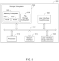
- FIG. 5 illustrates a block diagram of an example embodiment of a controller that can be used, for example, in the arc welding system of FIG. 1 .
- FIG. 1 illustrates a block diagram of one embodiment of an arc welding system 100 configured to provide a short circuit arc welding process having improved performance stability.
- the welding system 100 includes a power conversion circuit 110 providing welding output power between a welding electrode E and a work piece W.
- the power conversion circuit 110 may be transformer based with a bridge output topology (e.g. a half bridge output topology).
- the power conversion circuit 110 may be of an inverter type that includes an input power side and an output power side as delineated by the primary and secondary sides, respectively, of a welding transformer.
- Other types of power conversion circuits are possible as well such as, for example, a chopper type have a DC output topology.
- a wire feeder 5 feeds the consumable wire welding electrode E toward the work piece W.
- the wire feeder 5 , the consumable welding electrode E, and the work piece W can be considered to be a part of the welding system 100 and are operatively connected to other parts of the system 100 via, for example, welding output cables.
- the welding system 100 also includes a waveform generator 120 and a controller 130 .
- the waveform generator 120 generates welding waveforms (e.g., a short circuit welding waveform) at the command of the controller 130 .
- a waveform generated by the waveform generator 120 modulates the output of the power conversion circuit 110 to produce the welding output current between the electrode E and the work piece W.
- the welding system 100 also includes a voltage feedback circuit 140 and a current feedback circuit 150 to monitor the welding output voltage and current between the electrode E and the work piece W and provide the monitored voltage and current back to the controller 130 .
- the feedback voltage and current may be used by the controller 130 to make decisions with respect to modifying the welding waveform generated by the waveform generator 120 and/or to make other decisions that affect safe operation of the welding system 100 .
- the controller 130 may use the feedback voltage and/or the feedback current to determine when a short of the electrode E to the work piece W has occurred, and when a molten metal ball on the tip of the electrode E is about to pinch off from the tip of the electrode E and into a weld puddle (pool) on the work piece W.
- FIG. 4 of U.S. Pat. No. 5,001,326, which is incorporated herein by reference, is referred to, in order to establish some definitions.
- a short circuit welding waveform is shown.
- the short circuit welding waveform could be produced by the arc welding system 100 of FIG. 1 herein.
- the waveform includes (with respect to welding output current) a background phase, a pinch phase, a peak phase, and a tail-out phase.
- a first low current transition section In between the background phase and the pinch phase is a first low current transition section.
- a second low current transition section is also, in between the pinch phase and the peak phase.
- a molten metal ball is produced at the tip of the welding electrode E during the background phase.
- the molten metal ball shorts to the work piece W and the current is reduced, allowing the molten metal ball to wet into the weld puddle on the work piece W.
- a dual ramp pinch current is applied to the short to help the molten metal ball pinch off from the end of the electrode E into the weld puddle on the work piece W.
- the current is reduced, allowing a welding arc to easily re-establish between the electrode E and the work piece W after the molten metal ball has pinched off from the electrode E, clearing the short.
- peak current is applied to set the proper arc length of the re-established arc and to begin melting a new molten metal ball from the tip of the electrode E.
- generated heat is controlled by controlling the rate at which the current transitions from a peak current level to a background current level of the next background phase. The waveform repeats during the welding process to form a weld.
- the term “pinch phase”, as used herein, refers to the portion of a short circuit arc welding waveform where a “pinch pulse” (PP) welding output current is produced.
- the pinch phase is entered when a molten metal ball on the tip of a welding electrode first shorts to a work piece, and ends when the molten metal ball pinches off from the tip of the welding electrode and enters the weld puddle (pool).
- the welding current of the PP is controlled to initially ramp (e.g., upwards) at a first rate (having a first steep slope) towards a break point (BP), as seen in FIG. 4 of U.S. Pat. No.
- the welding current of the PP is controlled to ramp (e.g., further upwards) at a second rate (having a second gradual slope) where the welding current eventually reaches a necking threshold level (e.g., a peak level of the PP) before dropping, as seen in FIG. 4 of U.S. Pat. No. 5,001,326.
- a necking threshold level e.g., a peak level of the PP
- the break point (BP) is that point during the pinch phase where the welding current is transitioned from the first steep slope to the second gradual slope.
- the welding output is said to be at a BP welding current level or a BP welding energy level (e.g., a surface tension transfer (STT) pinch current level).
- STT surface tension transfer
- an STT switch may be part of the power conversion circuit 110 to help effect the break point.
- the necking threshold is the point where a short exit detection is triggered (a premonition of a short exit), indicating that the molten metal ball is about to pinch off from the tip of the welding electrode and enter the weld puddle (pool).
- the welding output is said to be at a necking threshold current level (or a necking threshold energy level).
- the term “energy” is used broadly herein (e.g., when referring to a value of necking threshold, a value of break point, and values of certain pinch calculations using same). To the extent that energy is proportional to current and power (where an increase in current can correspond to an increase in energy or power, and where a decrease in current can correspond to a decrease in energy or power), the term “energy” may refer to energy, current, or power. Also, standard units of energy and/or current and/or power do not necessarily have to be used with respect to all aspects of certain embodiments of the present invention, as long as a relative consistency is maintained. For example, a scaled version of current (amps) may be used to represent power or energy. What matters are the relationships of the parameter values (e.g., necking threshold value, break point value, actual pinch value, specified pinch value) with respect to each other, as discussed in more detail later herein.
- the parameter values e.g., necking threshold value, break point value, actual pinch value, specified pinch value
- the controller 130 of the arc welding system 100 monitors and stores a necking threshold energy in the form of data points.
- the stored necking threshold energy is put through a rolling average of previous short circuit energy captures and is then used to determine a relationship with respect to a break point (BP) energy to form a pinch energy relationship (e.g., as a ratio or a percentage).
- a value of the real time (actual) pinch energy relationship is compared to a previously specified and desired pinch energy relationship value stored in a weld table (e.g., in a memory of the controller 130 ). Based on the result of the comparison, the break point (BP) energy is adjusted to drive the pinch energy relationship to the desired value. This provides consistent stability for the short circuit welding process, even while welding parameters are changing during the welding process.
- FIG. 2 illustrates one embodiment of a portion of a short circuit arc welding waveform 200 , produced by the system 100 of FIG. 1 for the short circuit welding process, showing a break point 210 and a necking threshold 220 .
- the BP 210 and the necking threshold 220 are each points on the pinch pulse within the pinch phase 230 .
- the pinch phase 230 has a first steep slope portion 205 (a first ramp) and a second gradual slope portion 215 (a second ramp) as seen in FIG. 2 .
- a peak pulse, occurring during a peak phase 240 after the pinch pulse, is also shown.
- the break point 210 which is automatically and dynamically adjusted upwards or downwards (corresponding to a break point energy being automatically adjusted upwards or downwards) to maintain the actual pinch energy to be at a specified pinch energy.
- the necking threshold energy is determined from at least one of the welding current and the welding voltage of the short circuit arc welding waveform output at the necking threshold
- the break point energy is determined from at least one of the welding current and the welding voltage of the short circuit arc welding waveform output at the break point (e.g., as monitored by the voltage feedback circuit 140 and/or the current feedback circuit 150 ).
- the actual pinch energy is expressed as a pinch energy relationship value
- the specified pinch energy is expressed as a specified pinch energy relationship value.
- the relationship is between the necking threshold energy and the break point energy.
- a Pinch Relationship Energy using a RA Necking Threshold Energy and a Break Point Energy
- a sliding window average of necking threshold values e.g., energy values
- N being a positive integer
- Other types of averages of necking threshold values (and/or break point values) may be used, in accordance with other embodiments.
- the term “energy” is used broadly herein (e.g., when referring to a value of necking threshold, a value of break point, and values of certain pinch calculations using same). To the extent that energy is proportional to current and power (where an increase in current can correspond to an increase in energy or power, and where a decrease in current can correspond to a decrease in energy or power), the term “energy” may refer to energy, current, or power. Also, standard units of energy and/or current and/or power do not necessarily have to be used with respect to all aspects of certain embodiments of the present invention, as long as a relative consistency is maintained. For example, a normalized version of watts (amps ⁇ volts) may be used to represent power or energy. What matters are the relationships of the parameter values (e.g., necking threshold value, break point value, actual pinch value, specified pinch value) with respect to each other.
- the parameter values e.g., necking threshold value, break point value, actual pinch value, specified pinch value
- FIG. 3 illustrates how a welding output voltage 310 , a welding output current 320 , and a welding output resistance 330 behave near the necking threshold of the short circuit welding waveform output, in accordance with one embodiment.
- a short exists between the welding electrode and the work piece just before the necking threshold. Just after the necking threshold, the short is exited or cleared and an arc is re-established between the welding electrode and the work piece.
- FIG. 4 illustrates a flow chart of one embodiment of a method 400 for providing improved stability in a short circuit arc welding process by dynamically adjusting a break point (BP) during welding.
- a short circuit arc welding waveform output having a pinch phase with a break point and a necking threshold, is generated between a welding electrode and a work piece during a short circuit arc welding process.
- a necking threshold energy of the short circuit arc welding waveform output is monitored during the short circuit arc welding process and a running average of the necking threshold energy is generated.
- the necking threshold energy corresponds to an energy at the necking threshold in the pinch phase where a premonition of a short exit is detected, indicating that a molten metal ball is about to pinch off from a tip of the welding electrode and enter a weld puddle on the work piece.
- a break point energy of the short circuit arc welding waveform output is monitored during the short circuit arc welding process.
- the break point energy corresponds to an energy at the break point in the pinch phase where a current of the short circuit arc welding output is transitioned from a first steep slope to a second gradual slope.
- an actual pinch energy relationship value is calculated based on the running average of the necking threshold energy and the break point energy.
- the actual pinch energy relationship value is compared to a previously specified pinch energy relationship value.
- the break point energy of the short circuit arc welding waveform output is adjusted in response to the comparing to maintain the actual pinch energy relationship value to be at the specified pinch energy relationship value. In this manner, improved and consistent stability for the short circuit welding process is achieved, even while welding parameters are changing during the welding process.
- FIG. 5 illustrates a block diagram of an example embodiment of a controller 500 that can be used, for example, as the controller 130 in the arc welding system 100 of FIG. 1 .
- the controller 500 includes at least one processor 514 (e.g., a microprocessor, a central processing unit, a graphics processing unit) which communicates with a number of peripheral devices via bus subsystem 512 .
- peripheral devices may include a storage subsystem 524 , including, for example, a memory subsystem 528 and a file storage subsystem 526 , user interface input devices 522 , user interface output devices 520 , and a network interface subsystem 516 .
- the input and output devices allow user interaction with the controller 500 .
- Network interface subsystem 516 provides an interface to outside networks and is coupled to corresponding interface devices in other devices.
- User interface input devices 522 may include a keyboard, pointing devices such as a mouse, trackball, touchpad, or graphics tablet, a scanner, a touchscreen incorporated into the display, audio input devices such as voice recognition systems, microphones, and/or other types of input devices.
- pointing devices such as a mouse, trackball, touchpad, or graphics tablet
- audio input devices such as voice recognition systems, microphones, and/or other types of input devices.
- use of the term “input device” is intended to include all possible types of devices and ways to input information into the controller 500 or onto a communication network.
- User interface output devices 520 may include a display subsystem, a printer, or non-visual displays such as audio output devices.
- the display subsystem may include a cathode ray tube (CRT), a flat-panel device such as a liquid crystal display (LCD), a projection device, or some other mechanism for creating a visible image.
- the display subsystem may also provide non-visual display such as via audio output devices.
- output device is intended to include all possible types of devices and ways to output information from the controller 500 to the user or to another machine or computer system.
- Storage subsystem 524 stores programming and data constructs that provide some or all of the functionality described herein.
- Computer-executable instructions and data are generally executed by processor 514 alone or in combination with other processors.
- Memory 528 used in the storage subsystem 524 can include a number of memories including a main random access memory (RAM) 530 for storage of instructions and data during program execution and a read only memory (ROM) 532 in which fixed instructions are stored.
- a file storage subsystem 526 can provide persistent storage for program and data files, and may include a hard disk drive, a solid state drive, a floppy disk drive along with associated removable media, a CD-ROM drive, an optical drive, or removable media cartridges.
- the computer-executable instructions and data implementing the functionality of certain embodiments may be stored by file storage subsystem 526 in the storage subsystem 524 , or in other machines accessible by the processor(s) 514 .
- Bus subsystem 512 provides a mechanism for letting the various components and subsystems of the controller 500 communicate with each other as intended. Although bus subsystem 512 is shown schematically as a single bus, alternative embodiments of the bus subsystem may use multiple buses.
- the controller 500 can be of varying types. Due to the ever-changing nature of computing devices and networks, the description of the controller 500 depicted in FIG. 5 is intended only as a specific example for purposes of illustrating some embodiments. Many other configurations of a controller are possible, having more or fewer components than the controller 500 depicted in FIG. 5 .
Landscapes
- Engineering & Computer Science (AREA)
- Physics & Mathematics (AREA)
- Plasma & Fusion (AREA)
- Mechanical Engineering (AREA)
- Theoretical Computer Science (AREA)
- Arc Welding Control (AREA)
Abstract
Description
Pinch Energy=RA Necking Threshold Energy/Break Point Energy.
Pinch Energy (%)=(RA Necking Threshold Energy/Break Point Energy)×100
or
Pinch Energy (%)=(Break Point Energy/RA Necking Threshold Energy)×100.
Pinch Energy=RA Necking Threshold Energy−Break Point Energy.
Pinch Energy=(RA Necking Threshold Energy−Break Point Energy)/RA Necking Threshold Energy.
Pinch Energy=(RA Necking Threshold Energy−Break Point Energy)/Break Point Energy.
Claims (20)
Priority Applications (1)
| Application Number | Priority Date | Filing Date | Title |
|---|---|---|---|
| US17/465,352 US12194574B2 (en) | 2021-09-02 | 2021-09-02 | System and method for adapting break point for short circuit welding |
Applications Claiming Priority (1)
| Application Number | Priority Date | Filing Date | Title |
|---|---|---|---|
| US17/465,352 US12194574B2 (en) | 2021-09-02 | 2021-09-02 | System and method for adapting break point for short circuit welding |
Publications (2)
| Publication Number | Publication Date |
|---|---|
| US20230066991A1 US20230066991A1 (en) | 2023-03-02 |
| US12194574B2 true US12194574B2 (en) | 2025-01-14 |
Family
ID=85285621
Family Applications (1)
| Application Number | Title | Priority Date | Filing Date |
|---|---|---|---|
| US17/465,352 Active 2043-11-16 US12194574B2 (en) | 2021-09-02 | 2021-09-02 | System and method for adapting break point for short circuit welding |
Country Status (1)
| Country | Link |
|---|---|
| US (1) | US12194574B2 (en) |
Citations (10)
| Publication number | Priority date | Publication date | Assignee | Title |
|---|---|---|---|---|
| US5001326A (en) | 1986-12-11 | 1991-03-19 | The Lincoln Electric Company | Apparatus and method of controlling a welding cycle |
| US7109439B2 (en) | 2004-02-23 | 2006-09-19 | Lincoln Global, Inc. | Short circuit arc welder and method of controlling same |
| US20090127242A1 (en) | 2005-02-28 | 2009-05-21 | Kei Aimi | Control method for arc welding apparatus and arc welding apparatus |
| US20130264323A1 (en) | 2012-04-05 | 2013-10-10 | Lincoln Global, Inc. | Process for surface tension transfer short ciruit welding |
| US8969764B2 (en) | 2011-11-09 | 2015-03-03 | Lincoln Global, Inc. | Apparatus and method for short circuit welding with AC waveform |
| US9035218B2 (en) | 2009-08-10 | 2015-05-19 | Fronius International Gmbh | Method for short-arc welding and welding device for short-arc welding |
| US9120172B2 (en) | 2012-09-24 | 2015-09-01 | Lincoln Global, Inc. | Systems and methods providing controlled AC arc welding processes |
| US20150283638A1 (en) | 2014-04-04 | 2015-10-08 | Lincoln Global, Inc. | Method and system to use ac welding waveform and enhanced consumable to improve welding of galvanized workpiece |
| US20160288235A1 (en) | 2015-03-31 | 2016-10-06 | Illinois Tool Works Inc. | Controlled short circuit welding system and method |
| US20200316704A1 (en) | 2016-10-07 | 2020-10-08 | Illinois Tool Works Inc. | System and Method for Short Arc Welding |
-
2021
- 2021-09-02 US US17/465,352 patent/US12194574B2/en active Active
Patent Citations (10)
| Publication number | Priority date | Publication date | Assignee | Title |
|---|---|---|---|---|
| US5001326A (en) | 1986-12-11 | 1991-03-19 | The Lincoln Electric Company | Apparatus and method of controlling a welding cycle |
| US7109439B2 (en) | 2004-02-23 | 2006-09-19 | Lincoln Global, Inc. | Short circuit arc welder and method of controlling same |
| US20090127242A1 (en) | 2005-02-28 | 2009-05-21 | Kei Aimi | Control method for arc welding apparatus and arc welding apparatus |
| US9035218B2 (en) | 2009-08-10 | 2015-05-19 | Fronius International Gmbh | Method for short-arc welding and welding device for short-arc welding |
| US8969764B2 (en) | 2011-11-09 | 2015-03-03 | Lincoln Global, Inc. | Apparatus and method for short circuit welding with AC waveform |
| US20130264323A1 (en) | 2012-04-05 | 2013-10-10 | Lincoln Global, Inc. | Process for surface tension transfer short ciruit welding |
| US9120172B2 (en) | 2012-09-24 | 2015-09-01 | Lincoln Global, Inc. | Systems and methods providing controlled AC arc welding processes |
| US20150283638A1 (en) | 2014-04-04 | 2015-10-08 | Lincoln Global, Inc. | Method and system to use ac welding waveform and enhanced consumable to improve welding of galvanized workpiece |
| US20160288235A1 (en) | 2015-03-31 | 2016-10-06 | Illinois Tool Works Inc. | Controlled short circuit welding system and method |
| US20200316704A1 (en) | 2016-10-07 | 2020-10-08 | Illinois Tool Works Inc. | System and Method for Short Arc Welding |
Also Published As
| Publication number | Publication date |
|---|---|
| US20230066991A1 (en) | 2023-03-02 |
Similar Documents
| Publication | Publication Date | Title |
|---|---|---|
| US11969834B2 (en) | Real time resistance monitoring of an arc welding circuit | |
| CN102441728B (en) | Arc welding device and arc welding system | |
| US9662736B2 (en) | CO2 globular transfer | |
| JP7499434B2 (en) | Arc welding method and arc welding apparatus | |
| US9393636B2 (en) | Systems and methods to facilitate the starting and stopping of arc welding processes | |
| JP5038206B2 (en) | Constriction detection control method for consumable electrode arc welding | |
| CN104936736A (en) | Waveform compensation system and method for compensation of inductive phenomena in welding control | |
| JP7742530B2 (en) | Arc welding method and arc welding device | |
| CN108687430A (en) | System and method for arc welding and welding wire manipulation and control | |
| US12194574B2 (en) | System and method for adapting break point for short circuit welding | |
| CN114641364B (en) | Method and apparatus for welding a weld | |
| JP7319238B2 (en) | Arc welding control method, welding power source, welding system and detection method | |
| US11931835B2 (en) | Welding system for mitigating gun damage in pulsed arc welding | |
| JP5871360B2 (en) | Constriction detection control method for consumable electrode arc welding | |
| US12337425B2 (en) | Arc welding adjustable short circuit threshold | |
| JP7396779B2 (en) | Arc welding control method | |
| JP7489582B2 (en) | Arc welding method and arc welding apparatus | |
| US20240217018A1 (en) | Wire manipulation with ac waveform | |
| JP2019130588A (en) | Arc welding control method | |
| JP6941410B2 (en) | Pulse arc welding control method | |
| JP2026016906A (en) | Arc welding method and arc welding control program | |
| JP2022159881A (en) | Arc welding method and arc welding apparatus |
Legal Events
| Date | Code | Title | Description |
|---|---|---|---|
| AS | Assignment |
Owner name: LINCOLN GLOBAL, INC., CALIFORNIA Free format text: ASSIGNMENT OF ASSIGNORS INTEREST;ASSIGNORS:FLEMING, DANIEL P.;HENRY, JUDAH B.;REEL/FRAME:057374/0079 Effective date: 20210902 |
|
| FEPP | Fee payment procedure |
Free format text: ENTITY STATUS SET TO UNDISCOUNTED (ORIGINAL EVENT CODE: BIG.); ENTITY STATUS OF PATENT OWNER: LARGE ENTITY |
|
| STPP | Information on status: patent application and granting procedure in general |
Free format text: DOCKETED NEW CASE - READY FOR EXAMINATION |
|
| STPP | Information on status: patent application and granting procedure in general |
Free format text: NOTICE OF ALLOWANCE MAILED -- APPLICATION RECEIVED IN OFFICE OF PUBLICATIONS |
|
| STPP | Information on status: patent application and granting procedure in general |
Free format text: PUBLICATIONS -- ISSUE FEE PAYMENT VERIFIED |
|
| STCF | Information on status: patent grant |
Free format text: PATENTED CASE |