EP1747875A2 - Vorrichtung zum Stapeln von Teilen aus thermoplastischem Kunststoff - Google Patents
Vorrichtung zum Stapeln von Teilen aus thermoplastischem Kunststoff Download PDFInfo
- Publication number
- EP1747875A2 EP1747875A2 EP06014975A EP06014975A EP1747875A2 EP 1747875 A2 EP1747875 A2 EP 1747875A2 EP 06014975 A EP06014975 A EP 06014975A EP 06014975 A EP06014975 A EP 06014975A EP 1747875 A2 EP1747875 A2 EP 1747875A2
- Authority
- EP
- European Patent Office
- Prior art keywords
- receiving plate
- link
- holder
- stacking station
- guide pin
- Prior art date
- Legal status (The legal status is an assumption and is not a legal conclusion. Google has not performed a legal analysis and makes no representation as to the accuracy of the status listed.)
- Granted
Links
- 239000012815 thermoplastic material Substances 0.000 title claims description 3
- 230000000087 stabilizing effect Effects 0.000 claims description 14
- 238000000034 method Methods 0.000 claims description 8
- 238000004080 punching Methods 0.000 claims description 3
- 238000010276 construction Methods 0.000 claims description 2
- 230000006641 stabilisation Effects 0.000 claims description 2
- 238000011105 stabilization Methods 0.000 claims description 2
- 238000006073 displacement reaction Methods 0.000 description 3
- 238000000465 moulding Methods 0.000 description 2
- 239000004033 plastic Substances 0.000 description 2
- 230000001174 ascending effect Effects 0.000 description 1
- 230000000712 assembly Effects 0.000 description 1
- 238000000429 assembly Methods 0.000 description 1
- 238000001816 cooling Methods 0.000 description 1
- 238000004519 manufacturing process Methods 0.000 description 1
- 230000000630 rising effect Effects 0.000 description 1
- 238000004904 shortening Methods 0.000 description 1
- 238000003860 storage Methods 0.000 description 1
Images

Classifications
-
- B—PERFORMING OPERATIONS; TRANSPORTING
- B65—CONVEYING; PACKING; STORING; HANDLING THIN OR FILAMENTARY MATERIAL
- B65G—TRANSPORT OR STORAGE DEVICES, e.g. CONVEYORS FOR LOADING OR TIPPING, SHOP CONVEYOR SYSTEMS OR PNEUMATIC TUBE CONVEYORS
- B65G57/00—Stacking of articles
- B65G57/02—Stacking of articles by adding to the top of the stack
- B65G57/16—Stacking of articles of particular shape
- B65G57/165—Stacking of articles of particular shape nested
-
- B—PERFORMING OPERATIONS; TRANSPORTING
- B65—CONVEYING; PACKING; STORING; HANDLING THIN OR FILAMENTARY MATERIAL
- B65G—TRANSPORT OR STORAGE DEVICES, e.g. CONVEYORS FOR LOADING OR TIPPING, SHOP CONVEYOR SYSTEMS OR PNEUMATIC TUBE CONVEYORS
- B65G47/00—Article or material-handling devices associated with conveyors; Methods employing such devices
- B65G47/02—Devices for feeding articles or materials to conveyors
- B65G47/04—Devices for feeding articles or materials to conveyors for feeding articles
- B65G47/06—Devices for feeding articles or materials to conveyors for feeding articles from a single group of articles arranged in orderly pattern, e.g. workpieces in magazines
- B65G47/08—Devices for feeding articles or materials to conveyors for feeding articles from a single group of articles arranged in orderly pattern, e.g. workpieces in magazines spacing or grouping the articles during feeding
- B65G47/084—Devices for feeding articles or materials to conveyors for feeding articles from a single group of articles arranged in orderly pattern, e.g. workpieces in magazines spacing or grouping the articles during feeding grouping articles in a predetermined 2-dimensional pattern
- B65G47/086—Devices for feeding articles or materials to conveyors for feeding articles from a single group of articles arranged in orderly pattern, e.g. workpieces in magazines spacing or grouping the articles during feeding grouping articles in a predetermined 2-dimensional pattern cubiform articles
-
- B—PERFORMING OPERATIONS; TRANSPORTING
- B65—CONVEYING; PACKING; STORING; HANDLING THIN OR FILAMENTARY MATERIAL
- B65G—TRANSPORT OR STORAGE DEVICES, e.g. CONVEYORS FOR LOADING OR TIPPING, SHOP CONVEYOR SYSTEMS OR PNEUMATIC TUBE CONVEYORS
- B65G47/00—Article or material-handling devices associated with conveyors; Methods employing such devices
- B65G47/74—Feeding, transfer, or discharging devices of particular kinds or types
- B65G47/90—Devices for picking-up and depositing articles or materials
- B65G47/901—Devices for picking-up and depositing articles or materials provided with drive systems with rectilinear movements only
-
- B—PERFORMING OPERATIONS; TRANSPORTING
- B29—WORKING OF PLASTICS; WORKING OF SUBSTANCES IN A PLASTIC STATE IN GENERAL
- B29C—SHAPING OR JOINING OF PLASTICS; SHAPING OF MATERIAL IN A PLASTIC STATE, NOT OTHERWISE PROVIDED FOR; AFTER-TREATMENT OF THE SHAPED PRODUCTS, e.g. REPAIRING
- B29C51/00—Shaping by thermoforming, i.e. shaping sheets or sheet like preforms after heating, e.g. shaping sheets in matched moulds or by deep-drawing; Apparatus therefor
- B29C51/26—Component parts, details or accessories; Auxiliary operations
- B29C51/44—Removing or ejecting moulded articles
Definitions
- the invention relates to a device for stacking ejected from a combined Mehrfachform- and punching parts made of thermoplastic material, comprising a receiving plate with the number of molds corresponding receptacles for the takeover of the ejected parts and a stacking station, wherein the receiving plate between the multiple mold and the stacking station can be moved and swiveled through 180 °.
- a device of this kind is from the EP 1 000 887 B 1 known.
- There recordings for the ejected parts are provided on both sides of the receiving plate.
- the receiving plate is moved to the stacking process by a multi-mold to the stacking station and the recorded on the opposite side of the receiving plate from the previous machine cycle parts are spent to the stacking station, after which the receiving plate is turned so that the free shots are ready to receive new parts.
- the previously recorded parts thus go through during the turning process another machine cycle of the mold to subject the recorded parts of a longer cooling time.
- the object of the invention is to simplify the receiving plate with the recordings and to simplify the transfer process from the forming station to the stacking station and to accelerate.
- the receiving plate has a projecting in the opposite direction to the receptacle holder on which acts on a driving point at least one driver, which is connected to a linear drive that the holder has at least one guide pin having a greater distance from the receiving plate than the Mit supportivetician that at least one gate is provided for the at least one guide pin, which is arranged between the molding tool and the stacking station and that the backdrop two linear sections and a V-shaped having extending section between the two linear section.
- the receiving plate By this configuration, it is possible to receive the ejected from the multiple mold parts, to move by means of the linear drive in the direction of the stacking station, wherein the displacement process takes place so that the receiving plate initially retains its position due to the first linear portion of the backdrop, then while passing through of the guide pin is turned by the V-shaped portion of the link, so that then takes in the course of the second linear section, the receiving plate with the recorded parts a 180 ° pivoted position in which the recorded parts can be transferred to the stacking station.
- the recording plate thus has recordings on only one side and the recorded parts become passed during the sliding operation between the multiple mold and the stacking station during a machine cycle to the stacking station, whereupon within this machine cycle, the receiving plate is returned to the starting position to resume the newly formed parts can.
- the receiving plate has a pivot bearing whose axis coincides with the Mit Conversetician, this not only reduces the design effort, but limits the movement of the receiving plate to a minimum, which is advantageous for achieving a high number of cycles.
- a secure holder and guide the receiving plate which configuration is that at both ends of the holder in each case a driver and a Linear drive and a respective guide pin and a gate are provided.
- a driver, a linear drive, a guide pin and a link are provided at both ends of the holder for the receiving plate, so that the receiving plate is guided by two drive and guide assemblies safely, resulting in high speeds of movement is advantageous over a one-sided storage and leadership.
- the multiple mold and the stacking station are arranged at substantially the same height or there is a certain height difference, which requires a slight inclination of the linear drive.
- To achieve the pivoting movement of the receiving plate can of course be aligned up or down the V-shaped extending portion of the backdrop.
- the V-shaped extending portion of the backdrop is oriented starting from the linear sections down.
- a further advantageous embodiment according to the invention provides that outside the V-shaped portion of the gate symmetrically to this section a stabilizing backdrop is provided, into which a holder arranged on the stabilization pin engages with roller during the turning process of the receiving plate. This is intended to ensure that in the leadership of the receiving plate along the scenery uncontrolled pivoting back is exceeded when the inflection point of the V-shaped portion is exceeded.
- the stabilizing backdrop is designed as a guide slot lying on the line of symmetry of the V-shaped gate section into which the stabilizing pin is guided during the guidance of the guide pin V-shaped section of the scenery engages shortly before, during and shortly after the turning point. This ensures that takes place in the immediate direction of the inflection point of the V-shaped portion of the backdrop, the pivoting movement in the desired direction of rotation. The role allows a low-friction guidance of the stabilizing pin in the stabilizing backdrop.
- the drawing is limited only to the device for stacking plastic parts, that is to the device, which is provided between a combined Mehrfachform- and punching tool on the one hand and a stacking station for receiving the parts on the other.
- this device comprises a receiving plate 1 with a plurality of receptacles 2, which receive the ejected from the mold parts.
- 24 such receptacles are provided, which can accommodate at one stroke the ejected from the multiple mold 24 parts
- the receiving plate is supported by a holder 3, which engages over perforated struts 4 on the receiving plate.
- drivers 5 are defined at Mitauerticianen 6, which engage in a respective linear drive 7 and are fixed to timing belts or chains, not shown, which are driven by drive motors 8 to the driver and thus the receiving plate 1 between the not to move shown multiple mold and the stacking station, also not shown.
- the driving point 6 is at the same time pivot bearing for the receiving plate 1, which is pivoted on the way from the multiple mold to the stacking station by 180 ° in order to transfer the recorded parts, such as cups, in the stacking station.
- the pivot bearing is designated 9.
- a gate 10 which comprises two linear portions 11 and a V-shaped portion 12 which includes a descending portion 12a, an ascending portion 12b and a turning point 12c.
- this scenery 10 engages a holder 3 arranged on the guide pin 13, which has a greater distance from the receiving plate 1, as the driving point 6.
- the guide pin 13 moves in the verdekkten in Figure 3 linear portion 11 of the link 10, as long as the receptacles 2 the position, as shown in Figure 3.
- the receiving plate 1 When the guide pin 13 engages the V-shaped portion 12a, the receiving plate 1 is tilted until it is horizontal at the arrival of the guide pin 13 in the turning point 12c and the receptacles 2 are vertically upwards. If, during the further linear displacement of the holder 5, the latter is then displaced by the linear drive 7, then the guide pin 13 moves in the section 12b of the V-shaped gate section 12, whereby the receiving plate 1 is pivoted further until the receiving plate 1 is opposite the one shown in FIG shown position is pivoted by 180 °, so that the receptacles 2 are aligned in a direction opposite to the Figure 3 direction and thus can be retracted into the stacking station.
- a stabilizing pin 14 is provided with roller on the holder 3, which engages in a stabilizing link 15 when the guide pin 13 is in the turning point 12c of the V-shaped portion 12 of the gate 10.
- This stabilizing pin engages already in the stabilizing gate 15 when the guide pin 14 is located shortly before the turning point 12c and leaves this stabilizing backdrop when the guide pin 13 leaves the turning point in the direction of the second section 12b of the V-shaped section 12.
- the receiving plate 1 after passing through the guide pin 13 through the V-shaped portion 12 again pivoted back in the position shown in Figure 3 by 180 °, so that the receptacles 2 at the next machine cycle of the multi-mold can accommodate the ejected parts.
Landscapes
- Engineering & Computer Science (AREA)
- Mechanical Engineering (AREA)
- Moulds For Moulding Plastics Or The Like (AREA)
- Perforating, Stamping-Out Or Severing By Means Other Than Cutting (AREA)
- Pile Receivers (AREA)
- Braking Arrangements (AREA)
- Portable Nailing Machines And Staplers (AREA)
- Lining Or Joining Of Plastics Or The Like (AREA)
Abstract
Description
- Die Erfindung bezieht sich auf eine Vorrichtung zum Stapeln von aus einem kombinierten Mehrfachform- und Stanzwerkzeug ausgeschobenen Teilen aus thermoplastischem Kunststoff, umfassend eine Aufnahmeplatte mit der Anzahl der Formwerkzeuge entsprechenden Aufnahmen für die Übernahme der ausgeschobenen Teile sowie eine Stapelstation, wobei die Aufnahmeplatte zwischen dem Mehrfachformwerkzeug und der Stapelstation verfahrbar und um 180° schwenkbar ist.
- Eine Vorrichtung dieser Art ist aus der
EP 1 000 887 B 1 bekannt. Dort sind an beiden Seiten der Aufnahmeplatte Aufnahmen für die ausgeschobenen Teile vorgesehen. Die Aufnahmeplatte wird für den Stapelvorgang von einem Mehrfachformwerkzeug zur Stapelstation verschoben und dabei werden die auf der gegenüberliegenden Seite der Aufnahmeplatte aus dem vorhergehenden Maschinentakt aufgenommenen Teile zur Stapelstation verbracht, worauf die Aufnahmeplatte gewendet wird, so dass die freien Aufnahmen zur Aufnahme neuer Teile bereit sind. Die vorher aufgenommenen Teile durchlaufen also während des Wendevorganges einen weiteren Maschinentakt des Formwerkzeuges, um die aufgenommenen Teile einer längeren Kühlzeit zu unterwerfen. Dies erfordert eine Aufnahmeplatte mit doppelt so viel Aufnahmen wie Formnester in der Formmaschine vorhanden sind und außerdem einen umständlichen Verschiebevorgang mit eingeschlossenem Wendevorgang der Aufnahmeplatte, bei dem die aufgenommenen Teile erst bei dem zweiten Maschinentakt an die Stapelstation übergeben werden. - Aufgabe der Erfindung ist es, die Aufnahmeplatte mit den Aufnahmen zu vereinfachen und den Übergabevorgang von der Formstation zur Stapelstation zu vereinfachen und zu beschleunigen.
- Diese Aufgabe wird bei einer Vorrichtung nach dem Oberbegriff des Anspruchs 1 erfindungsgemäß dadurch gelöst, dass die Aufnahmeplatte einen in entgegengesetzter Richtung zu den Aufnahmen abstehenden Halter aufweist, an dem an einem Mitnehmerpunkt mindestens ein Mitnehmer angreift, der mit einem Linearantrieb verbunden ist, dass der Halter mindestens einen Führungszapfen aufweist, der von der Aufnahmeplatte einen größeren Abstand als der Mitnehmerpunkt aufweist, dass mindestens eine Kulisse für den mindestens einen Führungszapfen vorgesehen ist, die zwischen dem Formwerkzeug und der Stapelstation angeordnet ist und dass die Kulisse zwei lineare Abschnitte und einen V-förmig verlaufenden Abschnitt zwischen den beiden linearen Abschnitt aufweist.
- Durch diese Ausgestaltung ist es möglich, die aus dem Mehrfachformwerkzeug ausgeschobenen Teile aufzunehmen, mittels des Linearantriebes in Richtung auf die Stapelstation zu verschieben, wobei der Verschiebevorgang so erfolgt, dass die Aufnahmeplatte zunächst aufgrund des ersten linearen Abschnittes der Kulisse ihre Lage beibehält, dann beim Durchlaufen des Führungszapfens durch den V-förmigen Abschnitt der Kulisse gewendet wird, so dass dann im Verlauf des zweiten linearen Abschnittes die Aufnahmeplatte mit den aufgenommenen Teilen eine um 180° geschwenkte Lage einnimmt, in der die aufgenommenen Teile an die Stapelstation übergeben werden können. Die Aufnahmeplatte weist also nur an einer Seite Aufnahmen auf und die aufgenommenen Teile werden während des Verschiebevorganges zwischen dem Mehrfachformwerkzeug und der Stapelstation während eines Maschinentaktes an die Stapelstation übergeben, worauf innerhalb dieses Maschinentaktes die Aufnahmeplatte wieder in die Ausgangsstellung zurückgeführt wird, um die neu geformten Teile wieder aufnehmen zu können. Gegenüber dem Stande der Technik ist also eine Verringerung des Aufwandes bei der Aufnahmeplatte und eine Verkürzung des Stapelvorganges ermöglicht, denn die Aufnahmeplatte ist aufgrund dieser Kulissensteuerung in der Lage, während eines Maschinentaktes des Mehrfachformwerkzeuges die Teile aufzunehmen, an die Stapelstation überzugeben und wieder an den Ausgangspunkt zurückzukehren, um die Teile des zweiten Maschinentaktes aufnehmen zu können.
- Wenn in weiterer Ausgestaltung der Erfindung die Aufnahmeplatte ein Schwenklager aufweist, dessen Achse mit dem Mitnehmerpunkt zusammenfällt, so wird hierdurch nicht nur der konstruktive Aufwand verringert, sondern die Bewegung der Aufnahmeplatte auf ein Minimum beschränkt, was sich für die Erzielung einer hohen Taktzahl vorteilhaft auswirkt.
- Grundsätzlich ist zwar nach Anspruch 1 von einer einseitigen Anordnung eines Mitnehmers sowie einer Kulisse ausgegangen worden, jedoch dient eine weitere Ausgestaltung der Erfindung einer sicheren Halterung und Führung der Aufnahmeplatte, wobei diese Ausgestaltung darin besteht, dass an beiden Enden des Halters jeweils ein Mitnehmer und ein Linearantrieb sowie jeweils ein Führungszapfen und eine Kulisse vorgesehen sind. Hierdurch sind also an beiden Enden des Halters für die Aufnahmeplatte jeweils ein Mitnehmer, ein Linearantrieb, ein Führungszapfen und eine Kulisse vorgesehen, so dass die Aufnahmeplatte durch zwei Antriebs- und Führungsanordnungen sicher geführt ist, was bei hohen Bewegungsgeschwindigkeiten gegenüber einer einseitigen Lagerung und Führung vorteilhaft ist.
- In der Praxis werden das Mehrfachformwerkzeug und die Stapelstation im wesentlichen in gleicher Höhe angeordnet oder es besteht ein gewisser Höhenunterschied, der eine geringfügige Neigung des Linearantriebes erfordert. Zur Erzielung der Schwenkbewegung der Aufnahmeplatte kann selbstverständlich der V-förmig verlaufende Abschnitt der Kulisse nach oben oder unten ausgerichtet sein. In vorteilhafter Weiterbildung der Erfindung ist der V-förmig verlaufende Abschnitt der Kulisse ausgehend von den linearen Abschnitten nach unten ausgerichtet. Hierdurch ist die theoretisch mögliche Gefahr des Verlustes von gefertigten Teilen von den Aufnahmen mit Sicherheit vermieden.
- Um einen möglichst kurzen Weg zwischen dem Mehrformwerkzeug und der Stapelstation und damit eine hohe Taktzahl insbesondere bei der Herstellung von Bechern zu erreichen, ist in Weiterbildung der Erfindung vorgesehen, dass von den beiden linearen Abschnitte der Kulisse der zur Stapelstation ausgerichteten Abschnitt länger ist. Hierdurch wird der kürzeste Weg zwischen Formwerkzeug und Stapelstation ermöglicht, da die Kulisse gerade nur so lange ausgeführt ist, dass ein Verschwenken der Aufnahmeplatte um 180° durchgeführt werden kann. Der zum Formwerkzeug ausgerichtete Abschnitt kann kürzer sein, weil zum Aufnehmen eines Bechers ein kleinerer Verschiebeweg in der Kulisse notwendig ist als zum Einschieben eines Bechers über seinen Rand hinaus in die Stapelstation.
- Eine weitere vorteilhafte Ausgestaltung nach der Erfindung sieht vor, dass außerhalb des V-förmigen Abschnittes der Kulisse symmetrisch zu diesem Abschnitt eine Stabilisierungskulisse vorgesehen ist, in die ein am Halter angeordneter Stabilisierungsstift mit Rolle während des Wendevorganges der Aufnahmeplatte eingreift. Hierdurch soll erreicht werden, dass bei der Führung der Aufnahmeplatte entlang der Kulisse ein unkontrolliertes Zurückschwenken beim Überschreiten des Wendepunktes des V-förmigen Abschnittes ausgeschlossen wird.
- Um auch hinsichtlich der Stabilisierungskulisse eine möglichst einfache technische Lösung zu finden und einen sicheren Betriebsablauf zu gewährleisten ist vorgesehen, dass die Stabilisierungskulisse als ein auf der Symmetrielinie des V-förmigen Kulissenabschnittes liegender Führungsschlitz ausgebildet ist, in den der Stabilisierungsstift während der Führung des Führungszapfens an dem V-förmigen Abschnitt der Kulisse kurz vor, während und kurz nach dem Wendepunkt eingreift. Hierdurch ist sichergestellt, dass in unmittelbarer Nähe des Wendepunktes des V-förmigen Abschnittes der Kulisse die Schwenkbewegung in der gewünschten Drehrichtung stattfindet. Die Rolle ermöglicht eine reibungsarme Führung des Stabilisierungsstiftes in der Stabilisierungskulisse.
- Um einerseits den Linearantrieb möglichst einfach zu gestalten und dabei auch noch eine möglichst hohe Taktzahl bei der Bewegung der Aufnahmeplatte zu erreichen, ist in erfindungsgemäßer Ausgestaltung vorgesehen, dass die Aufnahmeplatte und der Halter sowie die damit verbundenen und am Schwenkvorgang teilnehmenden Teile in Leichtbauweise gefertigt sind.
- Die Erfindung wird nachfolgend anhand eines Ausführungsbeispiels näher erläutert. In der Zeichnung zeigen:
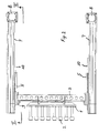
- Fig. 1 eine Vorderansicht der Vorrichtung zum Stapeln von Kunststoffteilen;
- Fig. 2 eine Ansicht von oben auf die Vorrichtung gemäß Figur 1; und
- Fig. 3 einen Schnitt nach der Linie III-III in Figur 2.
- Die zeichnerische Darstellung beschränkt sich nur auf die Vorrichtung zum Stapeln von aus Kunststoff bestehenden Teilen, das heißt auf die Vorrichtung, die zwischen einem kombinierten Mehrfachform- und Stanzwerkzeug einerseits und einer Stapelstation zur Aufnahme der Teile andererseits vorgesehen ist.
- Wie aus der Zeichnung ersichtlich, umfasst diese Vorrichtung eine Aufnahmeplatte 1 mit einer Vielzahl von Aufnahmen 2, welche die aus dem Formwerkzeug ausgeschobenen Teile aufnehmen. In dem dargestellten Ausführungsbeispiel sind 24 solcher Aufnahmen vorgesehen, die bei einem Arbeitstakt die aus dem Mehrfach-Formwerkzeug ausgeschobenen 24 Teile aufnehmen können An der diesen Aufnahmen entgegengesetzten Seite ist die Aufnahmeplatte von einem Halter 3 getragen, der über gelochte Streben 4 an der Aufnahmeplatte angreift. Zu beiden Seiten des Halters 3 sind Mitnehmer 5 an Mitnehmerpunkten 6 festgelegt, die in jeweils einen Linearantrieb 7 eingreifen und dort an nicht dargestellten Zahnriemen oder Ketten festgelegt sind, die von Antriebsmotoren 8 angetrieben werden, um die Mitnehmer und damit die Aufnahmeplatte 1 zwischen dem nicht dargestellten Mehrfach-Formwerkzeug und der ebenfalls nicht dargestellten Stapelstation bewegen zu können. Der Mitnehmerpunkt 6 ist gleichzeitig Schwenklager für die Aufnahmeplatte 1, die auf dem Weg von dem Mehrfachformwerkzeug zur Stapelstation um 180° geschwenkt wird, um die aufgenommenen Teile, beispielsweise Becher, in die Stapelstation übergeben zu können. Das Schwenklager ist mit 9 bezeichnet.
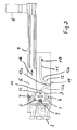
- Damit die Aufnahmeplatte 1 von der einen Einstellung, in der sie in den Figuren 2 und 3 dargestellt ist, in die um 180° geschwenkte Stellung überführt werden kann, ist eine Kulisse 10 vorgesehen, die zwei lineare Abschnitte 11 und einen V-förmigen Abschnitt 12 umfasst, der einen absteigenden Teil 12a, einen aufsteigenden Teil 12b und einen Wendepunkt 12c umfasst. In diese Kulisse 10 greift ein am Halter 3 angeordneter Führungszapfen 13 ein, der von der Aufnahmeplatte 1 einen größeren Abstand aufweist, als der Mitnehmerpunkt 6. Solange sich der Führungszapfen 13 in dem in Figur 3 verdekkten linearen Abschnitt 11 der Kulisse 10 bewegt, solange haben die Aufnahmen 2 die Position, wie sie in Figur 3 dargestellt ist. Wenn der Führungszapfen 13 in den V-förmigen Abschnitt 12a eingreift, wird die Aufnahmeplatte 1 gekippt, bis sie beim Eintreffen des Führungszapfens 13 im Wendepunkt 12c horizontal liegt und die Aufnahmen 2 vertikal nach oben stehen. Wird dann bei der weiteren Linearverschiebung des Halters 5 dieser durch den Linearantrieb 7 verschoben, so bewegt sich der Führungszapfen 13 in dem Abschnitt 12b des V-förmigen Kulissenabschnittes 12, wodurch die Aufnahmeplatte 1 weiter geschwenkt wird, bis die Aufnahmeplatte 1 gegenüber der in Figur 3 dargestellten Lage um 180° geschwenkt ist, so dass die Aufnahmen 2 in eine der Figur 3 entgegengesetzte Richtung ausgerichtet sind und somit in die Stapelstation eingefahren werden können.
- Damit im Wendepunkt 12c die Aufnahmeplatte 1 nicht unkontrolliert wieder zurückschwenkt, ist am Halter 3 ein Stabilisierungsstift 14 mit Rolle vorgesehen, der in eine Stabilisierungskulisse 15 eingreift, wenn sich der Führungszapfen 13 im Wendepunkt 12c des V-förmigen Abschnittes 12 der Kulisse 10 befindet. Dieser Stabilisierungsstift greift dabei schon in die Stabilisierungskulisse 15 ein, wenn sich der Führungszapfen 14 kurz vor dem Wendepunkt 12c befindet und verlässt diese Stabilisierungskulisse, wenn der Führungszapfen 13 den Wendepunkt in Richtung des zweiten Abschnittes 12b des V-förmigen Abschnittes 12 verlässt. Auf diese Weise wird sichergestellt, dass die Aufnahmeplatte 1 bei der Bewegung des Nehmers 5 in Richtung des Pfeils 16 auch in die richtige Richtung geschwenkt wird, so dass die Aufnahmen 2 in Richtung auf die nicht dargestellte Stapelstation ausgerichtet werden, wenn der Führungszapfen sich im aufsteigenden Bereich 12b des V-förmigen Abschnittes der Kulisse 10 bewegt und dann in den horizontalen Abschnitt 11 übergeht. Bei der Bewegung des Mitnehmers 5 in die dem Pfeil 16 entgegengesetzte Richtung, das heißt bei der Bewegung der Aufnahmeplatte 1 von der nicht dargestellten Stapelstation zurück zum Mehrfach-Formwerkzeug, wird die Aufnahmeplatte 1 nach Durchlaufen des Führungszapfens 13 durch den V-förmigen Abschnitt 12 wieder in die in Figur 3 dargestellte Lage um 180° zurückgeschwenkt, so dass die Aufnahmen 2 beim nächsten Maschinentakt des Mehrfach-Formwerkzeuges die ausgeschobenen Teile aufnehmen können.
- Während der Verschwenkung der Aufnahmeplatte 1 um 180° wird diese durch das Lager 9 gehalten, das zwischen dem Halter 3 und dem Mitnehmer 5 im Mitnehmerpunkt 6 angeordnet ist und so bei der Linearbewegung des Mitnehmers 5 in dem Linearantrieb 7 die Schwenkbewegung des Halters 3 und damit der Aufnahmeplatte 1 ermöglicht.
Claims (8)
- Vorrichtung zum Stapeln von aus einem kombinierten Mehrfachform- und Stanzwerkzeug ausgeschobenen Teilen aus thermoplastischem Kunststoff, umfassend eine Aufnahmeplatte (1) mit der Anzahl der Formwerkzeuge entsprechenden Aufnahmen (2) für die Übernahme der ausgeschobenen Teile sowie eine Stapelstation, wobei die Aufnahmeplatte (1) zwischen dem Mehrfachformwerkzeug und der Stapelstation verfahrbar und um 180° schwenkbar ist, dadurch gekennzeichnet, dass die Aufnahmeplatte (1) mindestens einen in entgegengesetzter Richtung zu den Aufnahmen abstehenden Halter (3) aufweist, an dem an einem Mitnehmerpunkt (6) mindestens ein Mitnehmer (5) angreift, der mit einem Linearantrieb (7) verbunden ist, dass der Halter (3) mindestens einen Führungszapfen (13) aufweist, der von der Aufnahmeplatte (1) einen größeren Abstand als der Mitnehmerpunkt (6) aufweist, dass eine Kulisse (10) für den mindestens einen Führungszapfen (13) vorgesehen ist, die zwischen dem Formwerkzeug und der Stapelstation angeordnet ist und dass die Kulisse (10) zwei lineare Abschnitte (11) und einen V-förmig verlaufenden Abschnitt (12) zwischen den beiden linearen Abschnitten aufweist.
- Vorrichtung nach Anspruch 1, dadurch gekennzeichnet, dass die Aufnahmeplatte (1) ein Schwenklager (9) aufweist, dessen Achse mit dem Mitnehmerpunkt (6) zusammenfällt.
- Vorrichtung nach Anspruch 1 oder 2, dadurch gekennzeichnet, dass an beiden Enden des Halters (3) jeweils ein Mitnehmer (5) und ein Linearantrieb (7) sowie jeweils ein Führungszapfen (13) und eine Kulisse (10) vorgesehen sind.
- Vorrichtung nach einem der Ansprüche 1 bis 3, dadurch gekennzeichnet, dass der V-förmig verlaufende Abschnitt (12) der Kulisse (10) ausgehend von den linearen Abschnitten (11) nach unten ausgerichtet ist.
- Vorrichtung nach einem der Ansprüche 1 bis 4, dadurch gekennzeichnet, dass von den beiden linearen Abschnitten (11) der Kulisse (10) der zur Stapelstation ausgerichtete Abschnitt länger ist.
- Vorrichtung nach einem der Ansprüche 1 bis 5, dadurch gekennzeichnet, dass außerhalb des V-förmigen Abschnittes (12) der Kulisse (10) symmetrisch zu diesem Abschnitt eine Stabilisierungskulisse (15) vorgesehen ist, in die ein am Halter (3) angeordneter Stabilisierungsstift (14) mit Rolle während des Wendevorganges der Aufnahmeplatte (1) eingreift.
- Vorrichtung nach einem der Anspruch 6, dadurch gekennzeichnet, dass die Stabilisierungskulisse (15) als ein auf der Symmetrielinie des V-förmigen Kulissenabschnittes (12) liegender Führungsschlitz ausgebildet ist, in den der Stabilisierungsstift (14) während der Führung des Führungszapfens (13) an den V-förmigen Abschnitten (12) der Kulisse (10) kurz vor, während, und kurz nach dem Wendepunkt (12c) eingreift.
- Vorrichtung nach einem der Ansprüche 1 bis 7, dadurch gekennzeichnet, dass die Aufnahmeplatte (1) und der Halter (3) sowie die damit verbundenen und am Schwenkvorgang teilnehmenden Teile in Leichtbauweise gefertigt sind.
Applications Claiming Priority (1)
| Application Number | Priority Date | Filing Date | Title |
|---|---|---|---|
| DE102005035459A DE102005035459B4 (de) | 2005-07-28 | 2005-07-28 | Vorrichtung zum Stapeln von Teilen aus thermoplastischem Kunststoff |
Publications (3)
| Publication Number | Publication Date |
|---|---|
| EP1747875A2 true EP1747875A2 (de) | 2007-01-31 |
| EP1747875A3 EP1747875A3 (de) | 2007-09-12 |
| EP1747875B1 EP1747875B1 (de) | 2008-07-09 |
Family
ID=37451549
Family Applications (1)
| Application Number | Title | Priority Date | Filing Date |
|---|---|---|---|
| EP06014975A Not-in-force EP1747875B1 (de) | 2005-07-28 | 2006-07-19 | Vorrichtung zum Stapeln von Teilen aus thermoplastischem Kunststoff |
Country Status (3)
| Country | Link |
|---|---|
| EP (1) | EP1747875B1 (de) |
| AT (1) | ATE400423T1 (de) |
| DE (2) | DE102005035459B4 (de) |
Cited By (4)
| Publication number | Priority date | Publication date | Assignee | Title |
|---|---|---|---|---|
| DE102008018104A1 (de) | 2008-04-09 | 2009-10-15 | Mould & Matic Solutions Gmbh | Vorrichtung zum Stapeln |
| WO2011115512A1 (en) * | 2010-03-13 | 2011-09-22 | Graham Packaging Company, L.P. | High-speed takeout system |
| CN103303689A (zh) * | 2013-06-20 | 2013-09-18 | 汕头市明发机械有限公司 | 超薄塑杯自动接杯堆叠装置 |
| CN114988126A (zh) * | 2022-07-18 | 2022-09-02 | 汕头市明发机械有限公司 | 一种一次性容具的加工堆叠输送设备 |
Families Citing this family (2)
| Publication number | Priority date | Publication date | Assignee | Title |
|---|---|---|---|---|
| ATE555892T1 (de) | 2009-05-14 | 2012-05-15 | Gabler Thermoform Gmbh & Co Kg | Vorrichtung zum stapeln von fertigartikeln aus thermoplastischem kunststoff |
| DE102016219074A1 (de) | 2016-09-30 | 2018-04-05 | Rudholzer Technologien GmbH | Stapelstation für eine Thermoformanlage |
Citations (4)
| Publication number | Priority date | Publication date | Assignee | Title |
|---|---|---|---|---|
| DE19710475A1 (de) * | 1997-03-13 | 1998-09-17 | Kuhne Anlagenbau Gmbh | Vorrichtung zur Herstellung von Hohlkörpern aus thermoplastisch verformbaren Kunststoff-Folien |
| DE19716655A1 (de) * | 1997-04-21 | 1998-10-22 | Gabler Gmbh Maschbau | Vorrichtung zum Formen, Stanzen und Stapeln von tiefgezogenen Teilen aus thermoplastischem Kunststoff |
| EP1052080A2 (de) * | 1999-05-11 | 2000-11-15 | Illig, Adolf Maschinenbau GmbH & Co. | Verfahren zum Bewegen eines Schwenktisches in einer Vorrichtung zum Formen und Ausstanzen von Behältern aus einer thermoplastischen Kunststofffolie und Vorrichtung zur Durchführung des verfahrens |
| EP1221365A1 (de) * | 2001-01-03 | 2002-07-10 | Adolf Illig Maschinenbau GmbH & Co. KG | Kombinierte Form-/Stanzstation zum Formen und Ausstanzen von Behältern aus einer Folienbahn aus thermoplastischem Kunststoff |
Family Cites Families (1)
| Publication number | Priority date | Publication date | Assignee | Title |
|---|---|---|---|---|
| DE19852359C1 (de) * | 1998-11-13 | 2000-08-31 | Illig Maschinenbau Adolf | Vorrichtung zum Aufnehmen und Stapeln von Behältern aus thermoplastischem Kunststoff |
-
2005
- 2005-07-28 DE DE102005035459A patent/DE102005035459B4/de not_active Expired - Fee Related
-
2006
- 2006-07-19 DE DE502006001051T patent/DE502006001051D1/de active Active
- 2006-07-19 EP EP06014975A patent/EP1747875B1/de not_active Not-in-force
- 2006-07-19 AT AT06014975T patent/ATE400423T1/de not_active IP Right Cessation
Patent Citations (4)
| Publication number | Priority date | Publication date | Assignee | Title |
|---|---|---|---|---|
| DE19710475A1 (de) * | 1997-03-13 | 1998-09-17 | Kuhne Anlagenbau Gmbh | Vorrichtung zur Herstellung von Hohlkörpern aus thermoplastisch verformbaren Kunststoff-Folien |
| DE19716655A1 (de) * | 1997-04-21 | 1998-10-22 | Gabler Gmbh Maschbau | Vorrichtung zum Formen, Stanzen und Stapeln von tiefgezogenen Teilen aus thermoplastischem Kunststoff |
| EP1052080A2 (de) * | 1999-05-11 | 2000-11-15 | Illig, Adolf Maschinenbau GmbH & Co. | Verfahren zum Bewegen eines Schwenktisches in einer Vorrichtung zum Formen und Ausstanzen von Behältern aus einer thermoplastischen Kunststofffolie und Vorrichtung zur Durchführung des verfahrens |
| EP1221365A1 (de) * | 2001-01-03 | 2002-07-10 | Adolf Illig Maschinenbau GmbH & Co. KG | Kombinierte Form-/Stanzstation zum Formen und Ausstanzen von Behältern aus einer Folienbahn aus thermoplastischem Kunststoff |
Cited By (4)
| Publication number | Priority date | Publication date | Assignee | Title |
|---|---|---|---|---|
| DE102008018104A1 (de) | 2008-04-09 | 2009-10-15 | Mould & Matic Solutions Gmbh | Vorrichtung zum Stapeln |
| WO2011115512A1 (en) * | 2010-03-13 | 2011-09-22 | Graham Packaging Company, L.P. | High-speed takeout system |
| CN103303689A (zh) * | 2013-06-20 | 2013-09-18 | 汕头市明发机械有限公司 | 超薄塑杯自动接杯堆叠装置 |
| CN114988126A (zh) * | 2022-07-18 | 2022-09-02 | 汕头市明发机械有限公司 | 一种一次性容具的加工堆叠输送设备 |
Also Published As
| Publication number | Publication date |
|---|---|
| EP1747875A3 (de) | 2007-09-12 |
| ATE400423T1 (de) | 2008-07-15 |
| DE102005035459B4 (de) | 2007-09-27 |
| EP1747875B1 (de) | 2008-07-09 |
| DE502006001051D1 (de) | 2008-08-21 |
| DE102005035459A1 (de) | 2007-02-08 |
Similar Documents
| Publication | Publication Date | Title |
|---|---|---|
| EP1747875B1 (de) | Vorrichtung zum Stapeln von Teilen aus thermoplastischem Kunststoff | |
| DE2550824C2 (de) | Karussell-Formmaschine | |
| DE2142117C3 (de) | Schneidvorrichtung zum Trennen bewegter Bahnen in deren Längsrichtung in mehrere schmälere Bahnen | |
| DE102009030012A1 (de) | Produktgreifer | |
| DE2163499A1 (de) | Werkzeugmaschine mit automatischer werkzeug-wechselvorrichtung | |
| DE102008007233A1 (de) | Schleifmaschine | |
| DE1927931A1 (de) | Rotierende Spritzformmaschine | |
| WO2017139819A1 (de) | Abkantpresse und verfahren zum wechseln von biegewerkzeugen einer abkantpresse | |
| EP0778094B1 (de) | Transfereinrichtung für Mehrstationenpressen | |
| DE2350810A1 (de) | Vorrichtung zur herstellung von behaeltern | |
| EP2944390A2 (de) | Biegewerkzeug sowie wechseleinheit hierfür | |
| DE102007028434B3 (de) | Vollautomatischer Niederhalter für ein Formwerkzeug | |
| DE2452420C2 (de) | Vorrichtung zum Aufbringen eines Trägers auf Behälter | |
| EP1634815A1 (de) | Drehstapelbehälter | |
| EP2456601B1 (de) | Vorrichtung zur reinigung von substraten an einem träger | |
| DE202007017726U1 (de) | Entformungsvorrichtung zum Entformen eines Werkstücks aus einem Formwerkzeug | |
| DE102010036184A1 (de) | Presse | |
| EP0829441B1 (de) | Vorrichtung zum Ausstossen gestapelter Druckbogen | |
| DE2222582A1 (de) | Transporteinrichtung fuer platinen an automatischen nutenstanzmaschinen | |
| EP0344573B1 (de) | Vorrichtung zum Lagern von Stückgut | |
| DE2747890B2 (de) | Vorrichtung zum Formen und Halten einer Banderole in einer Tiefziehform | |
| DE1940287A1 (de) | Automatische Abfuell- und Verschliessmaschine | |
| DE102005020617A1 (de) | Vorrichtung zum Aufrichten von Schalen und Behältern | |
| EP2087975B1 (de) | Vorrichtung zum Fügen und Verpressen von Korpusteilen zu einem Möbelkorpus | |
| DE3225326C2 (de) |
Legal Events
| Date | Code | Title | Description |
|---|---|---|---|
| PUAI | Public reference made under article 153(3) epc to a published international application that has entered the european phase |
Free format text: ORIGINAL CODE: 0009012 |
|
| AK | Designated contracting states |
Kind code of ref document: A2 Designated state(s): AT BE BG CH CY CZ DE DK EE ES FI FR GB GR HU IE IS IT LI LT LU LV MC NL PL PT RO SE SI SK TR |
|
| AX | Request for extension of the european patent |
Extension state: AL BA HR MK YU |
|
| PUAL | Search report despatched |
Free format text: ORIGINAL CODE: 0009013 |
|
| AK | Designated contracting states |
Kind code of ref document: A3 Designated state(s): AT BE BG CH CY CZ DE DK EE ES FI FR GB GR HU IE IS IT LI LT LU LV MC NL PL PT RO SE SI SK TR |
|
| AX | Request for extension of the european patent |
Extension state: AL BA HR MK YU |
|
| 17P | Request for examination filed |
Effective date: 20070824 |
|
| GRAP | Despatch of communication of intention to grant a patent |
Free format text: ORIGINAL CODE: EPIDOSNIGR1 |
|
| GRAS | Grant fee paid |
Free format text: ORIGINAL CODE: EPIDOSNIGR3 |
|
| AKX | Designation fees paid |
Designated state(s): AT BE BG CH CY CZ DE DK EE ES FI FR GB GR HU IE IS IT LI LT LU LV MC NL PL PT RO SE SI SK TR |
|
| GRAA | (expected) grant |
Free format text: ORIGINAL CODE: 0009210 |
|
| AK | Designated contracting states |
Kind code of ref document: B1 Designated state(s): AT BE BG CH CY CZ DE DK EE ES FI FR GB GR HU IE IS IT LI LT LU LV MC NL PL PT RO SE SI SK TR |
|
| REG | Reference to a national code |
Ref country code: GB Ref legal event code: FG4D Free format text: NOT ENGLISH |
|
| REG | Reference to a national code |
Ref country code: CH Ref legal event code: EP |
|
| REF | Corresponds to: |
Ref document number: 502006001051 Country of ref document: DE Date of ref document: 20080821 Kind code of ref document: P |
|
| REG | Reference to a national code |
Ref country code: IE Ref legal event code: FG4D Free format text: LANGUAGE OF EP DOCUMENT: GERMAN |
|
| REG | Reference to a national code |
Ref country code: CH Ref legal event code: NV Representative=s name: E. BLUM & CO. AG PATENT- UND MARKENANWAELTE VSP |
|
| REG | Reference to a national code |
Ref country code: CH Ref legal event code: PFA Owner name: MOULD AND MATIC SOLUTIONS GMBH Free format text: MOULD AND MATIC SOLUTIONS#ZIEHBERGSTRASSE 2#4563 MICHELDORF (AT) -TRANSFER TO- MOULD AND MATIC SOLUTIONS GMBH#ZIEHBERGSTRASSE 2#4563 MICHELDORF (AT) |
|
| PG25 | Lapsed in a contracting state [announced via postgrant information from national office to epo] |
Ref country code: LT Free format text: LAPSE BECAUSE OF FAILURE TO SUBMIT A TRANSLATION OF THE DESCRIPTION OR TO PAY THE FEE WITHIN THE PRESCRIBED TIME-LIMIT Effective date: 20080709 Ref country code: IS Free format text: LAPSE BECAUSE OF FAILURE TO SUBMIT A TRANSLATION OF THE DESCRIPTION OR TO PAY THE FEE WITHIN THE PRESCRIBED TIME-LIMIT Effective date: 20081109 |
|
| PG25 | Lapsed in a contracting state [announced via postgrant information from national office to epo] |
Ref country code: FI Free format text: LAPSE BECAUSE OF FAILURE TO SUBMIT A TRANSLATION OF THE DESCRIPTION OR TO PAY THE FEE WITHIN THE PRESCRIBED TIME-LIMIT Effective date: 20080709 Ref country code: PT Free format text: LAPSE BECAUSE OF FAILURE TO SUBMIT A TRANSLATION OF THE DESCRIPTION OR TO PAY THE FEE WITHIN THE PRESCRIBED TIME-LIMIT Effective date: 20081209 Ref country code: LV Free format text: LAPSE BECAUSE OF FAILURE TO SUBMIT A TRANSLATION OF THE DESCRIPTION OR TO PAY THE FEE WITHIN THE PRESCRIBED TIME-LIMIT Effective date: 20080709 Ref country code: ES Free format text: LAPSE BECAUSE OF FAILURE TO SUBMIT A TRANSLATION OF THE DESCRIPTION OR TO PAY THE FEE WITHIN THE PRESCRIBED TIME-LIMIT Effective date: 20081020 Ref country code: SI Free format text: LAPSE BECAUSE OF FAILURE TO SUBMIT A TRANSLATION OF THE DESCRIPTION OR TO PAY THE FEE WITHIN THE PRESCRIBED TIME-LIMIT Effective date: 20080709 Ref country code: BG Free format text: LAPSE BECAUSE OF FAILURE TO SUBMIT A TRANSLATION OF THE DESCRIPTION OR TO PAY THE FEE WITHIN THE PRESCRIBED TIME-LIMIT Effective date: 20081009 |
|
| NLT1 | Nl: modifications of names registered in virtue of documents presented to the patent office pursuant to art. 16 a, paragraph 1 |
Owner name: MOULD & MATIC SOLUTIONS GMBH |
|
| PG25 | Lapsed in a contracting state [announced via postgrant information from national office to epo] |
Ref country code: MC Free format text: LAPSE BECAUSE OF NON-PAYMENT OF DUE FEES Effective date: 20080731 |
|
| PG25 | Lapsed in a contracting state [announced via postgrant information from national office to epo] |
Ref country code: EE Free format text: LAPSE BECAUSE OF FAILURE TO SUBMIT A TRANSLATION OF THE DESCRIPTION OR TO PAY THE FEE WITHIN THE PRESCRIBED TIME-LIMIT Effective date: 20080709 Ref country code: DK Free format text: LAPSE BECAUSE OF FAILURE TO SUBMIT A TRANSLATION OF THE DESCRIPTION OR TO PAY THE FEE WITHIN THE PRESCRIBED TIME-LIMIT Effective date: 20080709 |
|
| PLBE | No opposition filed within time limit |
Free format text: ORIGINAL CODE: 0009261 |
|
| STAA | Information on the status of an ep patent application or granted ep patent |
Free format text: STATUS: NO OPPOSITION FILED WITHIN TIME LIMIT |
|
| PG25 | Lapsed in a contracting state [announced via postgrant information from national office to epo] |
Ref country code: RO Free format text: LAPSE BECAUSE OF FAILURE TO SUBMIT A TRANSLATION OF THE DESCRIPTION OR TO PAY THE FEE WITHIN THE PRESCRIBED TIME-LIMIT Effective date: 20080709 Ref country code: CZ Free format text: LAPSE BECAUSE OF FAILURE TO SUBMIT A TRANSLATION OF THE DESCRIPTION OR TO PAY THE FEE WITHIN THE PRESCRIBED TIME-LIMIT Effective date: 20080709 Ref country code: SK Free format text: LAPSE BECAUSE OF FAILURE TO SUBMIT A TRANSLATION OF THE DESCRIPTION OR TO PAY THE FEE WITHIN THE PRESCRIBED TIME-LIMIT Effective date: 20080709 |
|
| REG | Reference to a national code |
Ref country code: GB Ref legal event code: S117 Free format text: REQUEST FILED; REQUEST FOR CORRECTION UNDER SECTION 117 FILED ON 30 DECEMBER 2008 |
|
| 26N | No opposition filed |
Effective date: 20090414 |
|
| REG | Reference to a national code |
Ref country code: FR Ref legal event code: ST Effective date: 20090529 |
|
| PGFP | Annual fee paid to national office [announced via postgrant information from national office to epo] |
Ref country code: BE Payment date: 20090113 Year of fee payment: 3 |
|
| PG25 | Lapsed in a contracting state [announced via postgrant information from national office to epo] |
Ref country code: FR Free format text: LAPSE BECAUSE OF NON-PAYMENT OF DUE FEES Effective date: 20080731 |
|
| PGFP | Annual fee paid to national office [announced via postgrant information from national office to epo] |
Ref country code: AT Payment date: 20090724 Year of fee payment: 4 |
|
| REG | Reference to a national code |
Ref country code: GB Ref legal event code: S117 Free format text: CORRECTIONS ALLOWED; REQUEST FOR CORRECTION UNDER SECTION 117 FILED ON 30 DECEMBER 2008 ALLOWED ON 19 AUGUST 2009 |
|
| PG25 | Lapsed in a contracting state [announced via postgrant information from national office to epo] |
Ref country code: SE Free format text: LAPSE BECAUSE OF FAILURE TO SUBMIT A TRANSLATION OF THE DESCRIPTION OR TO PAY THE FEE WITHIN THE PRESCRIBED TIME-LIMIT Effective date: 20081009 |
|
| BERE | Be: lapsed |
Owner name: MOULD AND MATIC SOLUTIONS Effective date: 20090731 |
|
| PG25 | Lapsed in a contracting state [announced via postgrant information from national office to epo] |
Ref country code: PL Free format text: LAPSE BECAUSE OF FAILURE TO SUBMIT A TRANSLATION OF THE DESCRIPTION OR TO PAY THE FEE WITHIN THE PRESCRIBED TIME-LIMIT Effective date: 20080709 |
|
| PG25 | Lapsed in a contracting state [announced via postgrant information from national office to epo] |
Ref country code: BE Free format text: LAPSE BECAUSE OF NON-PAYMENT OF DUE FEES Effective date: 20090731 |
|
| PG25 | Lapsed in a contracting state [announced via postgrant information from national office to epo] |
Ref country code: HU Free format text: LAPSE BECAUSE OF FAILURE TO SUBMIT A TRANSLATION OF THE DESCRIPTION OR TO PAY THE FEE WITHIN THE PRESCRIBED TIME-LIMIT Effective date: 20090110 Ref country code: LU Free format text: LAPSE BECAUSE OF NON-PAYMENT OF DUE FEES Effective date: 20080719 Ref country code: CY Free format text: LAPSE BECAUSE OF FAILURE TO SUBMIT A TRANSLATION OF THE DESCRIPTION OR TO PAY THE FEE WITHIN THE PRESCRIBED TIME-LIMIT Effective date: 20080709 |
|
| PG25 | Lapsed in a contracting state [announced via postgrant information from national office to epo] |
Ref country code: TR Free format text: LAPSE BECAUSE OF FAILURE TO SUBMIT A TRANSLATION OF THE DESCRIPTION OR TO PAY THE FEE WITHIN THE PRESCRIBED TIME-LIMIT Effective date: 20080709 |
|
| PG25 | Lapsed in a contracting state [announced via postgrant information from national office to epo] |
Ref country code: GR Free format text: LAPSE BECAUSE OF FAILURE TO SUBMIT A TRANSLATION OF THE DESCRIPTION OR TO PAY THE FEE WITHIN THE PRESCRIBED TIME-LIMIT Effective date: 20081010 |
|
| PGFP | Annual fee paid to national office [announced via postgrant information from national office to epo] |
Ref country code: CH Payment date: 20100726 Year of fee payment: 5 Ref country code: IE Payment date: 20100722 Year of fee payment: 5 Ref country code: NL Payment date: 20100714 Year of fee payment: 5 |
|
| PGFP | Annual fee paid to national office [announced via postgrant information from national office to epo] |
Ref country code: GB Payment date: 20100722 Year of fee payment: 5 |
|
| REG | Reference to a national code |
Ref country code: NL Ref legal event code: V1 Effective date: 20120201 |
|
| REG | Reference to a national code |
Ref country code: CH Ref legal event code: PL |
|
| GBPC | Gb: european patent ceased through non-payment of renewal fee |
Effective date: 20110719 |
|
| REG | Reference to a national code |
Ref country code: AT Ref legal event code: MM01 Ref document number: 400423 Country of ref document: AT Kind code of ref document: T Effective date: 20110719 |
|
| REG | Reference to a national code |
Ref country code: IE Ref legal event code: MM4A |
|
| PG25 | Lapsed in a contracting state [announced via postgrant information from national office to epo] |
Ref country code: CH Free format text: LAPSE BECAUSE OF NON-PAYMENT OF DUE FEES Effective date: 20110731 Ref country code: LI Free format text: LAPSE BECAUSE OF NON-PAYMENT OF DUE FEES Effective date: 20110731 |
|
| PG25 | Lapsed in a contracting state [announced via postgrant information from national office to epo] |
Ref country code: NL Free format text: LAPSE BECAUSE OF NON-PAYMENT OF DUE FEES Effective date: 20120201 |
|
| PG25 | Lapsed in a contracting state [announced via postgrant information from national office to epo] |
Ref country code: GB Free format text: LAPSE BECAUSE OF NON-PAYMENT OF DUE FEES Effective date: 20110719 |
|
| PG25 | Lapsed in a contracting state [announced via postgrant information from national office to epo] |
Ref country code: IE Free format text: LAPSE BECAUSE OF NON-PAYMENT OF DUE FEES Effective date: 20110719 |
|
| PG25 | Lapsed in a contracting state [announced via postgrant information from national office to epo] |
Ref country code: AT Free format text: LAPSE BECAUSE OF NON-PAYMENT OF DUE FEES Effective date: 20110719 |
|
| PGFP | Annual fee paid to national office [announced via postgrant information from national office to epo] |
Ref country code: IT Payment date: 20180724 Year of fee payment: 13 |
|
| PG25 | Lapsed in a contracting state [announced via postgrant information from national office to epo] |
Ref country code: IT Free format text: LAPSE BECAUSE OF NON-PAYMENT OF DUE FEES Effective date: 20190719 |
|
| REG | Reference to a national code |
Ref country code: DE Ref legal event code: R082 Ref document number: 502006001051 Country of ref document: DE Representative=s name: DTS PATENT- UND RECHTSANWAELTE SCHNEKENBUEHL U, DE Ref country code: DE Ref legal event code: R082 Ref document number: 502006001051 Country of ref document: DE Representative=s name: FARAGO PATENTANWALTSGESELLSCHAFT MBH, DE Ref country code: DE Ref legal event code: R082 Ref document number: 502006001051 Country of ref document: DE Representative=s name: DTS PATENT- UND RECHTSANWAELTE PARTMBB, DE |
|
| REG | Reference to a national code |
Ref country code: DE Ref legal event code: R082 Ref document number: 502006001051 Country of ref document: DE Representative=s name: DTS PATENT- UND RECHTSANWAELTE SCHNEKENBUEHL U, DE Ref country code: DE Ref legal event code: R082 Ref document number: 502006001051 Country of ref document: DE Representative=s name: DTS PATENT- UND RECHTSANWAELTE PARTMBB, DE |
|
| PGFP | Annual fee paid to national office [announced via postgrant information from national office to epo] |
Ref country code: DE Payment date: 20220719 Year of fee payment: 17 |
|
| REG | Reference to a national code |
Ref country code: DE Ref legal event code: R119 Ref document number: 502006001051 Country of ref document: DE |
|
| PG25 | Lapsed in a contracting state [announced via postgrant information from national office to epo] |
Ref country code: DE Free format text: LAPSE BECAUSE OF NON-PAYMENT OF DUE FEES Effective date: 20240201 |