EP1746367B1 - Receiver dryer and receiver dryer integrated condenser - Google Patents
Receiver dryer and receiver dryer integrated condenser Download PDFInfo
- Publication number
- EP1746367B1 EP1746367B1 EP06405300A EP06405300A EP1746367B1 EP 1746367 B1 EP1746367 B1 EP 1746367B1 EP 06405300 A EP06405300 A EP 06405300A EP 06405300 A EP06405300 A EP 06405300A EP 1746367 B1 EP1746367 B1 EP 1746367B1
- Authority
- EP
- European Patent Office
- Prior art keywords
- condenser
- receiver dryer
- joint
- joint portion
- refrigerant
- Prior art date
- Legal status (The legal status is an assumption and is not a legal conclusion. Google has not performed a legal analysis and makes no representation as to the accuracy of the status listed.)
- Active
Links
- 238000010276 construction Methods 0.000 claims description 31
- 239000003507 refrigerant Substances 0.000 claims description 20
- 238000009987 spinning Methods 0.000 claims description 8
- 239000002274 desiccant Substances 0.000 claims description 6
- 238000003466 welding Methods 0.000 claims description 3
- 238000000465 moulding Methods 0.000 claims description 2
- 239000011347 resin Substances 0.000 claims description 2
- 229920005989 resin Polymers 0.000 claims description 2
- XLYOFNOQVPJJNP-UHFFFAOYSA-N water Substances O XLYOFNOQVPJJNP-UHFFFAOYSA-N 0.000 claims 1
- 230000003014 reinforcing effect Effects 0.000 description 4
- 230000003247 decreasing effect Effects 0.000 description 2
- 238000001035 drying Methods 0.000 description 2
- 239000004744 fabric Substances 0.000 description 2
- 238000005242 forging Methods 0.000 description 2
- 229910052751 metal Inorganic materials 0.000 description 2
- 239000002184 metal Substances 0.000 description 2
- 239000007769 metal material Substances 0.000 description 2
- 238000000034 method Methods 0.000 description 2
- 239000004745 nonwoven fabric Substances 0.000 description 2
- 238000003825 pressing Methods 0.000 description 2
- 238000004080 punching Methods 0.000 description 2
- 229910052782 aluminium Inorganic materials 0.000 description 1
- XAGFODPZIPBFFR-UHFFFAOYSA-N aluminium Chemical compound [Al] XAGFODPZIPBFFR-UHFFFAOYSA-N 0.000 description 1
- 238000002788 crimping Methods 0.000 description 1
- 238000009434 installation Methods 0.000 description 1
- 239000002991 molded plastic Substances 0.000 description 1
- 125000006850 spacer group Chemical group 0.000 description 1
Images


Classifications
-
- F—MECHANICAL ENGINEERING; LIGHTING; HEATING; WEAPONS; BLASTING
- F25—REFRIGERATION OR COOLING; COMBINED HEATING AND REFRIGERATION SYSTEMS; HEAT PUMP SYSTEMS; MANUFACTURE OR STORAGE OF ICE; LIQUEFACTION SOLIDIFICATION OF GASES
- F25B—REFRIGERATION MACHINES, PLANTS OR SYSTEMS; COMBINED HEATING AND REFRIGERATION SYSTEMS; HEAT PUMP SYSTEMS
- F25B39/00—Evaporators; Condensers
- F25B39/04—Condensers
-
- F—MECHANICAL ENGINEERING; LIGHTING; HEATING; WEAPONS; BLASTING
- F25—REFRIGERATION OR COOLING; COMBINED HEATING AND REFRIGERATION SYSTEMS; HEAT PUMP SYSTEMS; MANUFACTURE OR STORAGE OF ICE; LIQUEFACTION SOLIDIFICATION OF GASES
- F25B—REFRIGERATION MACHINES, PLANTS OR SYSTEMS; COMBINED HEATING AND REFRIGERATION SYSTEMS; HEAT PUMP SYSTEMS
- F25B43/00—Arrangements for separating or purifying gases or liquids; Arrangements for vaporising the residuum of liquid refrigerant, e.g. by heat
- F25B43/003—Filters
-
- F—MECHANICAL ENGINEERING; LIGHTING; HEATING; WEAPONS; BLASTING
- F25—REFRIGERATION OR COOLING; COMBINED HEATING AND REFRIGERATION SYSTEMS; HEAT PUMP SYSTEMS; MANUFACTURE OR STORAGE OF ICE; LIQUEFACTION SOLIDIFICATION OF GASES
- F25B—REFRIGERATION MACHINES, PLANTS OR SYSTEMS; COMBINED HEATING AND REFRIGERATION SYSTEMS; HEAT PUMP SYSTEMS
- F25B2339/00—Details of evaporators; Details of condensers
- F25B2339/04—Details of condensers
- F25B2339/044—Condensers with an integrated receiver
- F25B2339/0441—Condensers with an integrated receiver containing a drier or a filter
-
- F—MECHANICAL ENGINEERING; LIGHTING; HEATING; WEAPONS; BLASTING
- F25—REFRIGERATION OR COOLING; COMBINED HEATING AND REFRIGERATION SYSTEMS; HEAT PUMP SYSTEMS; MANUFACTURE OR STORAGE OF ICE; LIQUEFACTION SOLIDIFICATION OF GASES
- F25B—REFRIGERATION MACHINES, PLANTS OR SYSTEMS; COMBINED HEATING AND REFRIGERATION SYSTEMS; HEAT PUMP SYSTEMS
- F25B2500/00—Problems to be solved
- F25B2500/01—Geometry problems, e.g. for reducing size
Definitions
- the present invention relates to a receiver dryer for storing and drying a refrigerant for an air conditioner.
- a receiver dryer which is provided in an air conditioner for a motor vehicle to store and dry a refrigerant is required to decrease the number of parts and achieve a smaller size and lighter weight.
- Japanese Patent Publication No. 11-2475 discloses a receiver dryer of this type.
- Japanese Patent Publication No. 11-211275 discloses a receiver dryer assembled integrally to a condenser.
- FR-A-2 839 765 discloses a receiver dryer fixed to a condenser according to the preamble of claim 1.
- the above-described conventional receiver dryers have a construction in which the opening of a tank is closed by a closing member, and the closing member and a connector are connected to each other by bolts.
- An object of the present invention is to provide a receiver dryer in which a closing member and the like are omitted, the number and weight of parts are reduced, and the installation construction is simplified, and a receiver dryer integrated condenser.
- a receiver dryer is claimed in claim 1.
- the above-described taper-shaped portion need not necessarily be a taper if it can have a joint construction for fixing, which has a hole for allowing the refrigerant to pass through, the desiccant and the filter, and the strainer, and needless to say, can have a shape such that the diameter is decreased by a step shape.
- the joint construction can include a ring-shaped protruding portion formed in the outer periphery portion of the body by bulging and a fixing member for fixing the protruding portion to the condenser. Also, the joint construction can be threads that are formed on the body and are engaged threadedly with the condenser.
- the joint construction can include a groove formed in the body and a fixing member for fixing the groove to the condenser.
- the thickness of joint portion which has conventionally been needed for threadedly connecting the receiver dryer to the condenser can be decreased, so that a design can be made so that the joint portion has the same thickness as that of the body.
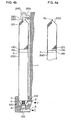
- FIG. 1 shows a basic construction of an assembly in which a receiver dryer 10 is integrated with a condenser 1.
- the condenser 1 has two refrigerant passages 2 and 3. In an opening portion 4 of the condenser 1, a joint portion of the receiver dryer is inserted, and the joint portion is sealed by seal members 5 and 6.
- the receiver dryer 10 is fixed to the condenser 1 by a mounting fixture 7.
- the receiver dryer 10 has a body 100 made by forging a metallic material and a joint portion 110 formed on the open end side of the body 100.
- the body 100 is filled with a desiccant 120, and a filter 130 made of nonwoven fabric cloth is inserted in the body 100.
- a reinforcing plate 140 made of punching metal or the like is inserted, and is fixed by a notch or a spinning portion K 1 .
- the joint portion 110 is formed into a tapered shape, and in the opening portion thereof at the tip end, a plastic-made strainer 150 is attached to prevent foreign matters in the flowing-out refrigerant from passing through.
- the taper surface is formed with a hole 112 through which the refrigerant flows in.
- FIG. 2 shows an example in which the joint portion 110 is constructed by a member 102 that is separate from the body 100.
- the joint member 102 is fabricated by pressing, and is joined to the body 100 by a welding portion W 1 .
- FIG. 3 is an explanatory view showing an assembly process of a receiver dryer in accordance with the present invention.
- the body 100 having the hole 112 for refrigerant in the vicinity of the open end is prepared.
- the filter 130 and the reinforcing plate 140 are inserted, and a notch portion K 1 is formed by pressing a notch forming tool T 1 from the outside of the body 100.
- This notch portion may be a plurality of points at the outer periphery, or may be a continuous groove.
- the opening portion is drawn into a tapered shape with a spinning tool ST to form the joint portion 110.
- the strainer 150 is inserted in an opening portion 113 of the joint portion 110, by which the receiver dryer is completed.
- FIG. 4a and FIG. 4b show an example in which the body is made by an aluminum pipe.
- FIG. 4a shows a construction in which a tip end portion 202 of an aluminum-pipe body 200 is drawn by spinning, and is sealed by a welding portion W 2 .
- FIG. 4b shows a construction in which a tip end portion 220 of the aluminum-made body 200 is drawn by spinning, and a bolt 230 is welded. By the use of this bolt 230, the body 200 is fixed to a mounting fixture 250 fixed on the condenser 1 side with a nut 240.
- the internal construction of the body 200 is the same as that of the body 100 in the above-described example.
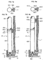
- FIG. 5a to FIG. 5d and FIG. 6 show various joint constructions for fixing the receiver dryer in accordance with the present invention to the condenser 1 side.
- FIG. 5a shows a joint construction in which a ring-shaped protruding portion 304 is formed on a body 300 of the receiver dryer by bulging, and a C ring 306 is fitted in the inlet portion of the opening portion 4 for joint of the condenser 1, by which the receiver dryer is fixed.
- the tip end of the body 300 is formed into a tapered shape, and a hole 302 through which the refrigerant sent from the inflow passage 2 passes is provided in the taper surface.
- the strainer 150 is inserted in the tip end portion of the body facing to the refrigerant outflow passage 3. Also, the two seal members 5 and 6 are disposed.
- FIG. 5b shows a joint construction in which a round thread portion 314 is formed at the tip end of the large-diameter portion of a body 310, by which the receiver dryer is fixed to the condenser 1 by being screwed in the condenser 1.
- Other constructions are the same as those of the above-described example.
- FIG. 5c shows a joint construction in which a thread portion 324 is formed at the tip end of the taper portion of a body 320, by which the receiver dryer is screwed in the condenser 1.
- FIG. 5d shows a joint construction in which a ring-shaped protruding portion 334 is formed on a body 330 by bulging, by which the body 330 is fixed to the condenser 1 by a cap nut 336.
- FIG. 6a to FIG. 6d and FIG. 6c', FIG. 6d', FIG. 6d" show other examples of joint constructions of the receiver dryer in accordance with the present invention.
- FIG. 6a shows a joint construction in which a ring-shaped protruding portion 404 is formed on a body 400 by bulging, and a crimping portion 406 is provided at the inlet of the opening portion 4 of the condenser 1, by which the body 400 is fixed.
- FIG. 6b shows a joint construction in which a groove 414 is formed in a body 410, and set screws 416 are turned in the condenser 1, by which the body 410 is fixed.
- FIG. 6c and Fig. 6c' show a joint construction in which a groove 424 is formed in a body 420, and a spacer 426 is inserted in a groove in the condenser 1, by which the body 420 is fixed.
- FIG. 6d and FIG. 6d' to FIG. 6d" show a joint construction in which a groove 434 is formed in a body 430, and a retaining ring 436 is used, by which the body 430 is fixed.
- FIG. 7a and FIG. 7b show an example of an assembling means for fixing the receiver dryer in accordance with the present invention to the condenser.
- a spinning portion K 1 for fixing the reinforcing plate 140 is provided at a middle position of the body 100 of the receiver dryer 10.
- a mounting portion 500 is provided on the condenser 1 side, and a ring band 510 for fixing is wound around the outer periphery of the body 100, by which the receiver dryer 10 is assembled to the condenser 1 by using a bolt 520 and a nut 522.
- FIG. 8a and FIG. 8b show another example of an assembling means for fixing the receiver dryer in accordance with the present invention to the condenser.
- the tip end portion on the opposite side to the joint portion 110 of the body 100 of the receiver dryer 10 is formed so as to have a small diameter to form a stepped portion 100a.
- a mounting portion 600 is provided on the condenser 1 side, and a ring band 610 is wound, by which the receiver dryer 10 is assembled to the condenser 1 by using a bolt 620 and a nut 622.
- the receiver dryer 10 Since the receiver dryer 10 is fixed to the condenser 1 by utilizing the stepped portion 100a, the axial movement of the body 100 can also be prevented surely.
- FIG. 9 shows an example of an assembly in which a receiver dryer is integrated with the condenser 1.
- the condenser 1 has the two refrigerant passages 2 and 3. In the opening portion 4 of the condenser 1, the joint portion of the receiver dryer is inserted, and the joint portion is sealed by the O-rings 5 and 6. A receiver dryer 10a is fixed to the condenser 1 by the mounting fixture 7.
- the receiver dryer 10a has the body 100 made by forging a metallic material and the joint portion 110 formed on the open end side of the body 100.
- the body 100 is filled with the desiccant 120, and the filter 130 made of nonwoven fabric cloth is inserted in the body 100.
- the reinforcing plate 140 made of punching metal or the like is inserted, and is fixed by the notch or the spinning portion K 1 .
- the joint portion 110 is formed into a tapered shape, and in the opening portion thereof at the tip end, the integrally molded plastic strainer 150 is attached to prevent foreign matters in the flowing-out refrigerant from passing through.
- the taper surface is formed with the hole 112 through which the refrigerant flows in.
- FIG. 10 shows a construction for assembling the joint portion 110 at the tip end of the body 100 of the receiver dryer 10a in accordance with another embodiment of the present invention to the condenser 1.
- the joint portion 110 has a taper portion 111 formed by drawing, and the taper portion 111 is provided with the hole 112 for allowing the refrigerant to pass through.
- a neck portion 114 is formed at the tip end of the taper portion 111.
- a first step portion 116 and a first cylindrical portion 117 having a smaller diameter are formed.
- the first O-ring 5 which is a seal member, is fitted.
- the condenser 1 is formed with a first stepped hole 5b that provides a space S for accommodating the first O-ring 5. By providing this stepped hole 5b, the annular groove for accommodating the O-ring can be omitted.
- This first O-ring 5 prevents the refrigerant that flows in through the refrigerant passage 2 from passing through the outer periphery portion of the cylindrical portion 117 and leaking to the outside of the condenser 1.
- the neck portion 114 at the tip end of the body 100 is inserted in the opening portion communicating with the refrigerant outflow passage 3.
- a second cylindrical portion 115 having a larger diameter than the neck portion 114 is provided between the taper portion 111 and the neck portion 114 of the joint portion 110. Between the second cylindrical portion 115 and the neck portion 114 is provided a second step portion 113. The second O-ring 6 is installed in the outer periphery portion of the neck portion 114 by utilizing this step portion 113.
- a second stepped hole 6a that provides a space S for accommodating the second O-ring 6 is formed.
- the annular groove for accommodating the second O-ring 6 can be omitted.
- the end portion on the opposite side of the body 100 is fixed by the mounting fixture 7, the first O-ring 5 supported by the step portion 116 and the second O-ring 6 supported by the step portion 113 can be held surely.
- the strainer 150 is inserted in the neck portion 114 of the body 100.
- the strainer 150 has a cylindrical portion 152 having a flange 153 and a mesh portion 154, and is manufactured integrally by molding a resin.
- the receiver dryer in accordance with the present invention is configured so that the body, which is a cylindrical vessel for storing and drying a refrigerant, is fixed directly to the condenser or directly to the condenser with the joint portion being provided on the body.
- the receiver dryer can be assembled integrally to the condenser, so that not only simplified construction but also smaller size and lighter weight can be achieved.
Landscapes
- Engineering & Computer Science (AREA)
- Physics & Mathematics (AREA)
- Mechanical Engineering (AREA)
- Thermal Sciences (AREA)
- General Engineering & Computer Science (AREA)
- Chemical & Material Sciences (AREA)
- Analytical Chemistry (AREA)
- Power Engineering (AREA)
- Air-Conditioning For Vehicles (AREA)
- Details Of Heat-Exchange And Heat-Transfer (AREA)
Applications Claiming Priority (2)
| Application Number | Priority Date | Filing Date | Title |
|---|---|---|---|
| JP2005209481A JP4836510B2 (ja) | 2005-07-20 | 2005-07-20 | レシーバドライヤ |
| JP2005265607A JP4489669B2 (ja) | 2005-09-13 | 2005-09-13 | レシーバドライヤ一体型コンデンサ |
Publications (3)
| Publication Number | Publication Date |
|---|---|
| EP1746367A2 EP1746367A2 (en) | 2007-01-24 |
| EP1746367A3 EP1746367A3 (en) | 2008-01-23 |
| EP1746367B1 true EP1746367B1 (en) | 2010-03-24 |
Family
ID=37114556
Family Applications (1)
| Application Number | Title | Priority Date | Filing Date |
|---|---|---|---|
| EP06405300A Active EP1746367B1 (en) | 2005-07-20 | 2006-07-12 | Receiver dryer and receiver dryer integrated condenser |
Country Status (5)
| Country | Link |
|---|---|
| US (1) | US7712330B2 (zh) |
| EP (1) | EP1746367B1 (zh) |
| KR (1) | KR101273868B1 (zh) |
| DE (1) | DE602006013072D1 (zh) |
| TW (1) | TW200722692A (zh) |
Families Citing this family (6)
| Publication number | Priority date | Publication date | Assignee | Title |
|---|---|---|---|---|
| CN103090695B (zh) * | 2008-12-15 | 2015-08-19 | 康奈可关精株式会社 | 换热器 |
| DE102011002976A1 (de) * | 2011-01-21 | 2012-07-26 | Behr Gmbh & Co. Kg | Kältemittelkondensatorbaugruppe |
| JP5631267B2 (ja) * | 2011-06-16 | 2014-11-26 | カルソニックカンセイ株式会社 | 複合型熱交換器の取付構造 |
| FR2978536B1 (fr) * | 2011-07-25 | 2013-08-23 | Valeo Systemes Thermiques | Bouteille reservoir de fluide refrigerant et echangeur de chaleur comprenant une telle bouteille |
| DE102013206357A1 (de) * | 2013-04-11 | 2014-10-16 | Behr Gmbh & Co. Kg | Sammler |
| EP3444545A1 (en) * | 2017-08-17 | 2019-02-20 | VALEO AUTOSYSTEMY Sp. Z. o.o. | Heat exchanger module with a bracket for holding a receiver drier |
Family Cites Families (14)
| Publication number | Priority date | Publication date | Assignee | Title |
|---|---|---|---|---|
| JPH0648283Y2 (ja) * | 1989-03-13 | 1994-12-12 | カルソニック株式会社 | リキッドタンク |
| JP3301169B2 (ja) | 1992-11-06 | 2002-07-15 | 株式会社デンソー | 冷凍装置 |
| JPH09217967A (ja) | 1996-02-13 | 1997-08-19 | Calsonic Corp | コンデンサのヘッダとリキッドタンクとの結合装置 |
| US5685364A (en) | 1996-03-15 | 1997-11-11 | Zexel Usa Corporation | Snap-on bracket for a condenser header |
| JPH112475A (ja) | 1997-06-12 | 1999-01-06 | Zexel Corp | リキッドタンクの取付構造 |
| JPH11101533A (ja) * | 1997-07-28 | 1999-04-13 | Zexel:Kk | レシーバタンク |
| FR2770629B1 (fr) | 1997-11-05 | 2000-02-11 | Valeo Thermique Moteur Sa | Condenseur de climatisation muni d'un reservoir de fluide interchangeable |
| FR2770896B1 (fr) | 1997-11-10 | 2000-01-28 | Valeo Thermique Moteur Sa | Condenseur de climatisation muni d'un reservoir de fluide a cartouche interchangeable |
| JP2001033121A (ja) | 1999-07-16 | 2001-02-09 | Denso Corp | 受液器一体型熱交換器、および受液器 |
| FR2799821B1 (fr) | 1999-09-28 | 2002-03-29 | Valeo Thermique Moteur Sa | Condenseur comprenant un reservoir fixe de maniere amovible et etanche sur une embase |
| JP3955770B2 (ja) * | 2001-03-02 | 2007-08-08 | 昭和電工株式会社 | レシーバタンク付き熱交換器及び冷凍システム |
| KR100827888B1 (ko) | 2001-03-02 | 2008-05-07 | 쇼와 덴코 가부시키가이샤 | 리시버 탱크를 갖는 열교환기, 및 냉동 시스템 |
| US6742355B2 (en) * | 2001-12-28 | 2004-06-01 | Calsonic Kansei Corporation | Receiver-drier for use in an air conditioning system |
| FR2839765B1 (fr) | 2002-05-15 | 2004-11-05 | Valeo Thermique Moteur Sa | Dispositif de connexion pour circuit de fluide, en particulier de climatisation, et circuit comportant un tel dispositif |
-
2006
- 2006-06-20 TW TW095122091A patent/TW200722692A/zh unknown
- 2006-06-26 US US11/474,612 patent/US7712330B2/en active Active
- 2006-07-04 KR KR1020060062502A patent/KR101273868B1/ko active IP Right Grant
- 2006-07-12 DE DE602006013072T patent/DE602006013072D1/de active Active
- 2006-07-12 EP EP06405300A patent/EP1746367B1/en active Active
Also Published As
| Publication number | Publication date |
|---|---|
| US20070017248A1 (en) | 2007-01-25 |
| TWI365275B (zh) | 2012-06-01 |
| KR101273868B1 (ko) | 2013-06-11 |
| TW200722692A (en) | 2007-06-16 |
| EP1746367A3 (en) | 2008-01-23 |
| EP1746367A2 (en) | 2007-01-24 |
| DE602006013072D1 (de) | 2010-05-06 |
| KR20070011102A (ko) | 2007-01-24 |
| US7712330B2 (en) | 2010-05-11 |
Similar Documents
| Publication | Publication Date | Title |
|---|---|---|
| EP1746367B1 (en) | Receiver dryer and receiver dryer integrated condenser | |
| EP2586513B1 (en) | Spin-on filter with external threads and methods | |
| US7175761B2 (en) | Fluid filter assembly | |
| US7434697B2 (en) | Disposable, spin-on filter | |
| JP3944706B2 (ja) | 2方向バルブ | |
| JP4836510B2 (ja) | レシーバドライヤ | |
| JP5270169B2 (ja) | 流体誘導接続を形成するための取付部品 | |
| JP4602892B2 (ja) | レシーバドライヤ一体型コンデンサ | |
| US11760146B2 (en) | Pressure body for a compressed-air system | |
| US4853125A (en) | Fluid chamber having a tubular filter and a securing recess for mounting the same | |
| KR101114074B1 (ko) | 오일 필터 조립체 | |
| US8361314B2 (en) | Single piece resilient combination bottom support and relief valve end seal element for fluid filters | |
| JP2010144935A (ja) | レシーバタンク | |
| JP2005127501A (ja) | 樹脂燃料タンク取付け用バルブ | |
| JP5624299B2 (ja) | レシーバドライヤ | |
| JP4489669B2 (ja) | レシーバドライヤ一体型コンデンサ | |
| WO2020019288A1 (zh) | 过滤组件、过滤组件的安装结构及进液管组件 | |
| US8636901B2 (en) | Two part resilient combination bottom support and relief valve end seal assembly for fluid filters | |
| CN105571218B (zh) | 储存干燥器 | |
| JP6643446B2 (ja) | レシーバドライヤ | |
| US20090250390A1 (en) | Filter | |
| JP2963801B2 (ja) | リキッドタンク | |
| EP4342561A1 (en) | Gas filter system | |
| JPH1157338A (ja) | 流体用フィルターの安全弁装置 |
Legal Events
| Date | Code | Title | Description |
|---|---|---|---|
| PUAI | Public reference made under article 153(3) epc to a published international application that has entered the european phase |
Free format text: ORIGINAL CODE: 0009012 |
|
| AK | Designated contracting states |
Kind code of ref document: A2 Designated state(s): AT BE BG CH CY CZ DE DK EE ES FI FR GB GR HU IE IS IT LI LT LU LV MC NL PL PT RO SE SI SK TR |
|
| AX | Request for extension of the european patent |
Extension state: AL BA HR MK YU |
|
| PUAL | Search report despatched |
Free format text: ORIGINAL CODE: 0009013 |
|
| AK | Designated contracting states |
Kind code of ref document: A3 Designated state(s): AT BE BG CH CY CZ DE DK EE ES FI FR GB GR HU IE IS IT LI LT LU LV MC NL PL PT RO SE SI SK TR |
|
| AX | Request for extension of the european patent |
Extension state: AL BA HR MK YU |
|
| 17P | Request for examination filed |
Effective date: 20080304 |
|
| 17Q | First examination report despatched |
Effective date: 20080409 |
|
| AKX | Designation fees paid |
Designated state(s): DE FR GB IT |
|
| GRAP | Despatch of communication of intention to grant a patent |
Free format text: ORIGINAL CODE: EPIDOSNIGR1 |
|
| GRAS | Grant fee paid |
Free format text: ORIGINAL CODE: EPIDOSNIGR3 |
|
| GRAA | (expected) grant |
Free format text: ORIGINAL CODE: 0009210 |
|
| AK | Designated contracting states |
Kind code of ref document: B1 Designated state(s): DE FR GB IT |
|
| REG | Reference to a national code |
Ref country code: GB Ref legal event code: FG4D |
|
| REF | Corresponds to: |
Ref document number: 602006013072 Country of ref document: DE Date of ref document: 20100506 Kind code of ref document: P |
|
| PLBE | No opposition filed within time limit |
Free format text: ORIGINAL CODE: 0009261 |
|
| STAA | Information on the status of an ep patent application or granted ep patent |
Free format text: STATUS: NO OPPOSITION FILED WITHIN TIME LIMIT |
|
| 26N | No opposition filed |
Effective date: 20101228 |
|
| GBPC | Gb: european patent ceased through non-payment of renewal fee |
Effective date: 20100712 |
|
| REG | Reference to a national code |
Ref country code: DE Ref legal event code: R084 Ref document number: 602006013072 Country of ref document: DE |
|
| PG25 | Lapsed in a contracting state [announced via postgrant information from national office to epo] |
Ref country code: GB Free format text: LAPSE BECAUSE OF NON-PAYMENT OF DUE FEES Effective date: 20100712 |
|
| REG | Reference to a national code |
Ref country code: DE Ref legal event code: R082 Ref document number: 602006013072 Country of ref document: DE Representative=s name: RACKETTE PATENTANWAELTE PARTG MBB, DE |
|
| REG | Reference to a national code |
Ref country code: FR Ref legal event code: PLFP Year of fee payment: 11 |
|
| REG | Reference to a national code |
Ref country code: FR Ref legal event code: PLFP Year of fee payment: 12 |
|
| REG | Reference to a national code |
Ref country code: FR Ref legal event code: PLFP Year of fee payment: 13 |
|
| PGFP | Annual fee paid to national office [announced via postgrant information from national office to epo] |
Ref country code: IT Payment date: 20230612 Year of fee payment: 18 Ref country code: FR Payment date: 20230620 Year of fee payment: 18 |
|
| PGFP | Annual fee paid to national office [announced via postgrant information from national office to epo] |
Ref country code: DE Payment date: 20230531 Year of fee payment: 18 |