EP1745977A1 - Electrical device cooling structure in vehicle - Google Patents
Electrical device cooling structure in vehicle Download PDFInfo
- Publication number
- EP1745977A1 EP1745977A1 EP06014074A EP06014074A EP1745977A1 EP 1745977 A1 EP1745977 A1 EP 1745977A1 EP 06014074 A EP06014074 A EP 06014074A EP 06014074 A EP06014074 A EP 06014074A EP 1745977 A1 EP1745977 A1 EP 1745977A1
- Authority
- EP
- European Patent Office
- Prior art keywords
- seat
- cooling
- electrical device
- air introduction
- floor
- Prior art date
- Legal status (The legal status is an assumption and is not a legal conclusion. Google has not performed a legal analysis and makes no representation as to the accuracy of the status listed.)
- Granted
Links
- 238000001816 cooling Methods 0.000 title claims abstract description 39
- 239000002828 fuel tank Substances 0.000 claims description 5
- 230000000694 effects Effects 0.000 description 3
- 230000001143 conditioned effect Effects 0.000 description 1
- 210000005069 ears Anatomy 0.000 description 1
- 230000002708 enhancing effect Effects 0.000 description 1
- 238000012986 modification Methods 0.000 description 1
- 230000004048 modification Effects 0.000 description 1
- 238000009751 slip forming Methods 0.000 description 1
Images







Classifications
-
- B—PERFORMING OPERATIONS; TRANSPORTING
- B60—VEHICLES IN GENERAL
- B60K—ARRANGEMENT OR MOUNTING OF PROPULSION UNITS OR OF TRANSMISSIONS IN VEHICLES; ARRANGEMENT OR MOUNTING OF PLURAL DIVERSE PRIME-MOVERS IN VEHICLES; AUXILIARY DRIVES FOR VEHICLES; INSTRUMENTATION OR DASHBOARDS FOR VEHICLES; ARRANGEMENTS IN CONNECTION WITH COOLING, AIR INTAKE, GAS EXHAUST OR FUEL SUPPLY OF PROPULSION UNITS IN VEHICLES
- B60K1/00—Arrangement or mounting of electrical propulsion units
- B60K1/04—Arrangement or mounting of electrical propulsion units of the electric storage means for propulsion
-
- B—PERFORMING OPERATIONS; TRANSPORTING
- B60—VEHICLES IN GENERAL
- B60N—SEATS SPECIALLY ADAPTED FOR VEHICLES; VEHICLE PASSENGER ACCOMMODATION NOT OTHERWISE PROVIDED FOR
- B60N2/00—Seats specially adapted for vehicles; Arrangement or mounting of seats in vehicles
- B60N2/24—Seats specially adapted for vehicles; Arrangement or mounting of seats in vehicles for particular purposes or particular vehicles
- B60N2/30—Non-dismountable or dismountable seats storable in a non-use position, e.g. foldable spare seats
- B60N2/3038—Cushion movements
- B60N2/3063—Cushion movements by composed movement
- B60N2/3068—Cushion movements by composed movement in a longitudinal-transversal plane
-
- B—PERFORMING OPERATIONS; TRANSPORTING
- B60—VEHICLES IN GENERAL
- B60N—SEATS SPECIALLY ADAPTED FOR VEHICLES; VEHICLE PASSENGER ACCOMMODATION NOT OTHERWISE PROVIDED FOR
- B60N2/00—Seats specially adapted for vehicles; Arrangement or mounting of seats in vehicles
- B60N2/24—Seats specially adapted for vehicles; Arrangement or mounting of seats in vehicles for particular purposes or particular vehicles
- B60N2/30—Non-dismountable or dismountable seats storable in a non-use position, e.g. foldable spare seats
- B60N2/3072—Non-dismountable or dismountable seats storable in a non-use position, e.g. foldable spare seats on a lower level of a multi-level vehicle floor
- B60N2/3075—Non-dismountable or dismountable seats storable in a non-use position, e.g. foldable spare seats on a lower level of a multi-level vehicle floor stowed in recess
-
- B—PERFORMING OPERATIONS; TRANSPORTING
- B60—VEHICLES IN GENERAL
- B60N—SEATS SPECIALLY ADAPTED FOR VEHICLES; VEHICLE PASSENGER ACCOMMODATION NOT OTHERWISE PROVIDED FOR
- B60N2/00—Seats specially adapted for vehicles; Arrangement or mounting of seats in vehicles
- B60N2/24—Seats specially adapted for vehicles; Arrangement or mounting of seats in vehicles for particular purposes or particular vehicles
- B60N2/32—Seats specially adapted for vehicles; Arrangement or mounting of seats in vehicles for particular purposes or particular vehicles convertible for other use
- B60N2/36—Seats specially adapted for vehicles; Arrangement or mounting of seats in vehicles for particular purposes or particular vehicles convertible for other use into a loading platform
-
- B—PERFORMING OPERATIONS; TRANSPORTING
- B60—VEHICLES IN GENERAL
- B60K—ARRANGEMENT OR MOUNTING OF PROPULSION UNITS OR OF TRANSMISSIONS IN VEHICLES; ARRANGEMENT OR MOUNTING OF PLURAL DIVERSE PRIME-MOVERS IN VEHICLES; AUXILIARY DRIVES FOR VEHICLES; INSTRUMENTATION OR DASHBOARDS FOR VEHICLES; ARRANGEMENTS IN CONNECTION WITH COOLING, AIR INTAKE, GAS EXHAUST OR FUEL SUPPLY OF PROPULSION UNITS IN VEHICLES
- B60K1/00—Arrangement or mounting of electrical propulsion units
- B60K2001/003—Arrangement or mounting of electrical propulsion units with means for cooling the electrical propulsion units
- B60K2001/005—Arrangement or mounting of electrical propulsion units with means for cooling the electrical propulsion units the electric storage means
-
- B—PERFORMING OPERATIONS; TRANSPORTING
- B60—VEHICLES IN GENERAL
- B60N—SEATS SPECIALLY ADAPTED FOR VEHICLES; VEHICLE PASSENGER ACCOMMODATION NOT OTHERWISE PROVIDED FOR
- B60N2/00—Seats specially adapted for vehicles; Arrangement or mounting of seats in vehicles
- B60N2/24—Seats specially adapted for vehicles; Arrangement or mounting of seats in vehicles for particular purposes or particular vehicles
- B60N2/32—Seats specially adapted for vehicles; Arrangement or mounting of seats in vehicles for particular purposes or particular vehicles convertible for other use
- B60N2/36—Seats specially adapted for vehicles; Arrangement or mounting of seats in vehicles for particular purposes or particular vehicles convertible for other use into a loading platform
- B60N2002/363—Seats specially adapted for vehicles; Arrangement or mounting of seats in vehicles for particular purposes or particular vehicles convertible for other use into a loading platform characterised by provisions for enhancing the cargo floor surface, e.g. elements closing gaps or enlarging the back-rest surface
Definitions
- the present invention relates to an electrical device cooling structure in a vehicle, in which an electrical device disposed under a rear floor to the rear of a foldable rear seat is cooled by cooling air introduced from inside a vehicle compartment.
- Japanese Patent Application Laid-open No. 2004-1683 discloses an electrical device cooling structure, in which a battery pack for driving a motor for driving an automobile is mounted in a luggage space to the rear of a rear seat, and an intake duct for supplying cooling air to the battery back opens sideways of a seat back of a rear seat.
- Japanese Patent Application Laid-open No. 2004-98722 discloses a so-called diving-down foldable seat, in which a seat cushion is moved downward and a seat back is declined forward to cause an upper surface of the thus-folded seat back to be continuous substantially flatly to a rear floor in the rear of a seat.
- Japanese Patent Application Laid-open No. 2004-1683 has a problem that because the intake duct for supplying the cooling air to the battery pack opens sideways of the seat back of the rear seat, the opening situates near an occupant's ear and generates nose. In order to avoid this problem, it is conceivable that the cooling air is supplied from below the rear seat to the battery pack.
- Japanese Patent Application Laid-open No. 2004-98722 it is difficult to secure a cooling-air passage when the seat is folded.
- an electrical device cooling structure in a vehicle including, a rear seat including a seat cushion and a seat back, the rear seat foldable by moving downward the seat cushion and folding forward the seat back so that an upper surface of the folded seat back becomes substantially flatly continuous to the rear floor which is located to the rear of the seat back; and a cooling-air introduction port provided in an electrical device which is disposed under a rear floor to drive a motor for driving the vehicle, cooling air being introduced into the cooling-air introduction port through a space between a lower surface of the seat cushion of the rear seat in an unfolded state and an upper surface of an underseat floor, wherein when the rear seat is in a folded state a cooling-air introduction passage is formed for introducing the cooling air in the vehicle compartment into the cooling-air introduction port in the electrical device.
- a luggage chamber having a larger capacity can be formed in a rear portion of a vehicle body, because of the provision of the rear seat foldable by moving downward the seat cushion and folding forward the seat back so that the upper surface of the folded seat back becomes substantially flatly continuous to the rear floor which is located to the rear of the seat back.
- the cooling air can be introduced from inside the vehicle compartment, through the space between the lower surface of the seat cushion and the upper surface of the underseat floor, into the cooling-air introduction port in the electrical device disposed below the rear floor to drive the motor for driving the vehicle.
- the cooling air can be introduced from inside the vehicle compartment, through the cooling-air introduction passage, into the cooling-air introduction port. Therefore, the electrical device can be cooled irrespective of whether the rear seat is in the folded state or the unfolded state.
- the cooling-air introduction passage is formed between the lower surface of the seat cushion of the rear seat in the folded state and the upper surface of the underseat floor.
- the cooling-air introduction passage is formed between the lower surface of the seat cushion of the rear seat in the folded state and the upper surface of the underseat floor. Therefore, the cooling-air introduction passage is located in a position distant and lower from the occupant's ear, thereby reducing noise.
- a fuel tank is disposed below a front seat located in front of the rear seat.
- the fuel tank is disposed introduction passage for introducing the cooling air into the cooling-air introduction port is not blocked by the fuel tank, thereby improving the effect of cooling the electrical device.
- a hollow cross member is disposed below the rear seat to interconnect left and right side frames, and the cooling-air introduction passage passes through the inside of the cross member.
- the cooling-air introduction passage passes through the inside of the hollow cross member interconnecting the left and right side frames below the rear seat. Therefore, it is possible to secure a sufficient sectional area of the cooling-air introduction passage, thereby improving the effect of cooling the electrical device.
- a bridge plate is pivotally supported at a front end of the rear floor so that the bridge plate covers a gap between the folded seat back and the rear floor.
- the gap between the folded seat back and the rear floor is covered by the bridge plate which is pivotally supported at the front end of the rear floor. Therefore, it is possible to eliminate a gap between the seat back and the rear floor, thereby improving the appearance and preventing the dropping-in of articles.
- the electrical device is at least one of a battery and a motor control device.
- a power source unit 19 in the above embodiments corresponds to the electrical device of the present invention
- a battery module 35 in the embodiments corresponds to the battery of the present invention.
- Figs.1 to 12 show a first embodiment of the present invention in which:
- Fig. 1 is a side view of the entire hybrid vehicle
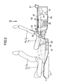
- Fig.2 is an enlarged view of essential portions of Fig.1;
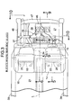
- Fig.3 is a view taken in a direction indicated by arrow 3 in Fig.2 (a use state of a rear seat);
- Fig.4 is a view taken in a direction indicated by arrow 3 in Fig.2 (a diving-down state of the rear seat);
- Fig.5 is a sectional view taken along a line 5-5 in Fig.3;
- Fig.6 is a sectional view taken along a line 6-6 in Fig.3;
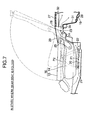
- Fig.7 is a sectional view taken along a line 7-7 in Fig.4;
- Fig.8 is a sectional view taken along a line 8-8 in Fig.4;
- Fig.9 is a sectional view taken along a line 9-9 in Fig.3;
- Fig.10 is a sectional view taken along a line 10-10 in Fig.3;
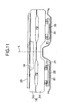
- Fig.11 is a sectional view taken along a line 11-11 in Fig.4;
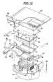
- Fig.12 is an exploded perspective view of a power source unit.
- Figs.13 and 14 show a second embodiment of the present invention
- Fig.13 is a view corresponding to Fig.3, but according to a second embodiment of the present invention.
- Fig. 14 is a sectional view taken along a line 14-14 in Fig. 13.
- a vehicle including an engine (not shown) and a motor (not shown) as driving sources includes, a front seat 13 including a seat cushion 11 and a seat back 12; and a rear seat 16 including a seat cushion 14 and a seat back 15.
- a fuel tank 17 is disposed below the seat cushion 11 of the front seat 13.
- a power source unit 19 for driving the motor is mounted below a luggage space 18 to the rear of the rear seat 16.
- a pair of left and right stays 20, 20 are foldably mounted on a lower surface of the seat cushion 14 of the rear seat 16.
- lower ends of the stays 20, 20 are engaged with hooks 22, 22 provided on an underseat floor 21 under the rear seat 16, and a rear end of the seat cushion 14 is engaged with a seat-cushion locking portion 24 provided on a bulging portion 23 in the rear of the underseat floor 21.
- the seat back 15 is capable of being folded down forward through a reclining shaft 25 mounted at the rear end of the seat cushion 14.
- a power-source-unit accommodating section 26 recessed downward is continuously formed rearward from the bulging portion 23 provided in the rear of the underseat floor 21.
- An opening in an upper surface of the power-source-unit accommodating section 26 is covered by a rear floor 27 constituting a floor of the luggage space 18.
- the height of the rear floor 27 is substantially the same as that of an upper surface of the seat cushion 14 of the rear seat 16 in a use state, and is also substantially the same as that of an upper surface of the seat back 15 of the rear seat 16 in a folded state.
- a bridge plate 29 is pivotally supported at a front end of the rear floor 27 through a hinge 28.
- the bridge plate 29 is swung forward to be placed on the upper surface of the seat back 15 (see Fig.7), thereby covering a gap between the rear floor 27 and the seat back 25 to prevent the dropping-in of articles.
- the power source unit 19 comprises a vessel-shaped lower case 31 and a lid-shaped upper case 32 which are coupled to each other by bolts 33.
- a laterally longer oblong cooling-air introduction port 34 opens forward between the lower case 31 and the upper case 32.
- a plurality of cylindrical battery modules 35 are bundled by a pair of holders 36, 36.
- a pair of front and rear battery support frames 37, 37 are fixed to upper surfaces of the holders 36, 36 by bolts 38.
- the battery support frames 37, 37 penetrate through upper portions of the lower case 31 to project in left and right directions, and are fixed at their end to left and right side frames 39, 39 by bolts 40.
- a heat transfer plate 41 and a control-unit accommodating box 42 are fastened together to upper surfaces of the battery support frames 37, 37 by bolts 43.
- a motor control device 44 such as PDU (a power drive unit) and D/B (a down-converter) is accommodated in the control-unit accommodating box 42.
- Two fans 45, 45 are disposed in the rear of the lower case 31 and the upper case 32.
- a cooling-air discharge port 46 is formed in the rear of the fans 45, 45.
- the cooling-air discharge port 46 faces an opening 47a in a cross member 47 which interconnects rear ends of the left and right side frames 39, 39, so that a portion of cooling air exiting the cooling-air discharge port 46 flows through the inside of the cross member 47, and is partially discharged to the outside of the vehicle and partially returned to the inside of the vehicle.
- a muffler 48 is disposed on a right side of a lower surface of a rear portion of the vehicle body.
- the power source unit 19 is slightly offset to the left side of the vehicle body with respect to a centerline L of the vehicle body, and correspondingly, the cooling-air introduction port 34 is also slightly offset to the left side of the vehicle body with respect to the centerline L of the vehicle body.
- the cooling-air introduction port 34 between the lower case 31 and the upper case 32 of the power source unit 19 opens toward the rear end of the seat cushion 14.
- the fans 45, 45 within the power source unit 19 are driven, conditioned cooling air existing in a space in front of the rear seat 16 is drawn rearward through a gap between the lower surface of the cooling-air introduction port 34 and the upper surface of the underseat floor 21, and flows through the cooling-air introduction port 34 into the lower case 31 and the upper case 32 of the power source unit 19.
- a portion of the cooling air cools the bundled battery modules 35 while flowing through gaps between the battery modules 35.
- Heat generated by the motor control device 44 accommodated in the control-unit accommodating box 42 is transmitted through a bottom wall of the control-unit accommodating box 42 to the heat transfer plate 41, and dissipated to the cooling air flowing along the lower surface of the heat transfer plate 41.
- the cooling air which has cooled the battery modules 35 and the motor control device 44 in this manner, is passed through the fans 45, 45 and discharged from the cooling-air discharge port 46.
- a first cooling-air introduction passage P1 is formed between the underseat floor 21 and the seat cushion 14
- a second cooling-air introduction passage P2 is formed between the seat cushion 14 and the seat back 15. Therefore, the cooling air within the vehicle compartment can be supplied to the cooling-air introduction port 34 without hindrance to cool the battery modules 35 and the motor control device 44.
- the cooling air within the vehicle compartment can be introduced into the cooling-air introduction port 34 by securing the first and second cooling-air introduction passages P1 and P2 along the folded rear seat 16, while forming a luggage chamber of a large capacity by connecting generally flatly the upper surface of the folded seat back 15 and the rear floor 27.
- the cooling air flows along the underseat floor 21 which is distant from the occupant's ears, thereby reducing noise heard by the occupant.
- a cross member 49 interconnecting left and right side frames 39, 39 is laterally disposed in the rear of a seat cushion 14 of a rear seat 16 in a folded state.
- the cross member 49 is formed to have a box-shaped section including a portion of a bulging portion 23 of a floor, and openings 49a and 49b are formed in front and upper surfaces of the cross member 49.
- the present invention is also applicable to a vehicle including a middle seat between the front seat 13 and the rear seat 16.
Landscapes
- Engineering & Computer Science (AREA)
- Transportation (AREA)
- Mechanical Engineering (AREA)
- Aviation & Aerospace Engineering (AREA)
- Chemical & Material Sciences (AREA)
- Combustion & Propulsion (AREA)
- Arrangement Or Mounting Of Propulsion Units For Vehicles (AREA)
- Cooling, Air Intake And Gas Exhaust, And Fuel Tank Arrangements In Propulsion Units (AREA)
- Body Structure For Vehicles (AREA)
- Secondary Cells (AREA)
Abstract
Description
- The
Japanese priority application No. 2005-208041 - The present invention relates to an electrical device cooling structure in a vehicle, in which an electrical device disposed under a rear floor to the rear of a foldable rear seat is cooled by cooling air introduced from inside a vehicle compartment.
-
Japanese Patent Application Laid-open No. 2004-1683 -
Japanese Patent Application Laid-open No. 2004-98722 - However,
Japanese Patent Application Laid-open No. 2004-1683 Japanese Patent Application Laid-open No. 2004-98722 - Accordingly, it is an object of the present invention to effectively cool an electrical device mounted in the rear of a rear seat without reducing the foldability of the rear seat.
- In order to achieve the above object, there is provided an electrical device cooling structure in a vehicle, including, a rear seat including a seat cushion and a seat back, the rear seat foldable by moving downward the seat cushion and folding forward the seat back so that an upper surface of the folded seat back becomes substantially flatly continuous to the rear floor which is located to the rear of the seat back; and a cooling-air introduction port provided in an electrical device which is disposed under a rear floor to drive a motor for driving the vehicle, cooling air being introduced into the cooling-air introduction port through a space between a lower surface of the seat cushion of the rear seat in an unfolded state and an upper surface of an underseat floor, wherein when the rear seat is in a folded state a cooling-air introduction passage is formed for introducing the cooling air in the vehicle compartment into the cooling-air introduction port in the electrical device.
- With the arrangement of the first feature, a luggage chamber having a larger capacity can be formed in a rear portion of a vehicle body, because of the provision of the rear seat foldable by moving downward the seat cushion and folding forward the seat back so that the upper surface of the folded seat back becomes substantially flatly continuous to the rear floor which is located to the rear of the seat back. When the rear seat is in an unfolded state, the cooling air can be introduced from inside the vehicle compartment, through the space between the lower surface of the seat cushion and the upper surface of the underseat floor, into the cooling-air introduction port in the electrical device disposed below the rear floor to drive the motor for driving the vehicle. When the rear seat is in a folded state, the cooling air can be introduced from inside the vehicle compartment, through the cooling-air introduction passage, into the cooling-air introduction port. Therefore, the electrical device can be cooled irrespective of whether the rear seat is in the folded state or the unfolded state.
- According to a second feature, in addition to the first feature, the cooling-air introduction passage is formed between the lower surface of the seat cushion of the rear seat in the folded state and the upper surface of the underseat floor.
- With the arrangement of the second feature, the cooling-air introduction passage is formed between the lower surface of the seat cushion of the rear seat in the folded state and the upper surface of the underseat floor. Therefore, the cooling-air introduction passage is located in a position distant and lower from the occupant's ear, thereby reducing noise.
- According to a third feature, in addition to the first or second feature, a fuel tank is disposed below a front seat located in front of the rear seat.
- With the arrangement of the third feature, the fuel tank is disposed introduction passage for introducing the cooling air into the cooling-air introduction port is not blocked by the fuel tank, thereby improving the effect of cooling the electrical device.
- According to a fourth feature, in addition to the first or second feature, a hollow cross member is disposed below the rear seat to interconnect left and right side frames, and the cooling-air introduction passage passes through the inside of the cross member.
- With the arrangement of the fourth feature, the cooling-air introduction passage passes through the inside of the hollow cross member interconnecting the left and right side frames below the rear seat. Therefore, it is possible to secure a sufficient sectional area of the cooling-air introduction passage, thereby improving the effect of cooling the electrical device.
- According to a fifth feature, in addition to the first or second feature, a bridge plate is pivotally supported at a front end of the rear floor so that the bridge plate covers a gap between the folded seat back and the rear floor.
- With the arrangement of the fifth feature, the gap between the folded seat back and the rear floor is covered by the bridge plate which is pivotally supported at the front end of the rear floor. Therefore, it is possible to eliminate a gap between the seat back and the rear floor, thereby improving the appearance and preventing the dropping-in of articles.
- According to a sixth feature, in addition to the first or second feature, the electrical device is at least one of a battery and a motor control device.
- With the arrangement of the sixth feature, it is possible to reliably cool the battery or the motor control device which is the electrical device heated due to the driving of the motor.
- A
power source unit 19 in the above embodiments corresponds to the electrical device of the present invention, and abattery module 35 in the embodiments corresponds to the battery of the present invention. - The above and other objects, features and advantages of the invention will become apparent from the following description of preferred embodiments taken in conjunction with the accompanying drawings.
- Figs.1 to 12 show a first embodiment of the present invention in which:
- Fig. 1 is a side view of the entire hybrid vehicle;
- Fig.2 is an enlarged view of essential portions of Fig.1;
- Fig.3 is a view taken in a direction indicated by
arrow 3 in Fig.2 (a use state of a rear seat); - Fig.4 is a view taken in a direction indicated by
arrow 3 in Fig.2 (a diving-down state of the rear seat); - Fig.5 is a sectional view taken along a line 5-5 in Fig.3;
- Fig.6 is a sectional view taken along a line 6-6 in Fig.3;
- Fig.7 is a sectional view taken along a line 7-7 in Fig.4;
- Fig.8 is a sectional view taken along a line 8-8 in Fig.4;
- Fig.9 is a sectional view taken along a line 9-9 in Fig.3;
- Fig.10 is a sectional view taken along a line 10-10 in Fig.3;
- Fig.11 is a sectional view taken along a line 11-11 in Fig.4; and
- Fig.12 is an exploded perspective view of a power source unit.
- Figs.13 and 14 show a second embodiment of the present invention
- Fig.13 is a view corresponding to Fig.3, but according to a second embodiment of the present invention; and
- Fig. 14 is a sectional view taken along a line 14-14 in Fig. 13.
- As shown in Figs. 1 to 3, a vehicle including an engine (not shown) and a motor (not shown) as driving sources includes, a
front seat 13 including aseat cushion 11 and aseat back 12; and arear seat 16 including aseat cushion 14 and a seat back 15. Afuel tank 17 is disposed below theseat cushion 11 of thefront seat 13. Apower source unit 19 for driving the motor is mounted below aluggage space 18 to the rear of therear seat 16. - A pair of left and
right stays seat cushion 14 of therear seat 16. In a state where therear seat 16 is used, lower ends of thestays hooks underseat floor 21 under therear seat 16, and a rear end of theseat cushion 14 is engaged with a seat-cushion locking portion 24 provided on a bulgingportion 23 in the rear of theunderseat floor 21. Theseat back 15 is capable of being folded down forward through a recliningshaft 25 mounted at the rear end of theseat cushion 14. - Therefore, when the rear end of the
seat cushion 14 is disengaged from the seat-cushion locking portion 24 on the bulgingportion 23, thestays hooks seat cushion 14 is shifted downward to a position closely along theunderseat floor 21 while being moved in parallel forward and downward. Then, therear seat 16 is folded by swinging the seat back 15 forward about the recliningshaft 25, so that theseat back 15 becomes substantially horizontal (see a dashed line in Fig.2). - A power-source-
unit accommodating section 26 recessed downward is continuously formed rearward from the bulgingportion 23 provided in the rear of theunderseat floor 21. An opening in an upper surface of the power-source-unit accommodating section 26 is covered by arear floor 27 constituting a floor of theluggage space 18. The height of therear floor 27 is substantially the same as that of an upper surface of theseat cushion 14 of therear seat 16 in a use state, and is also substantially the same as that of an upper surface of the seat back 15 of therear seat 16 in a folded state. Abridge plate 29 is pivotally supported at a front end of therear floor 27 through ahinge 28. In a state where the seat back 15 of therear seat 16 is folded forward, thebridge plate 29 is swung forward to be placed on the upper surface of the seat back 15 (see Fig.7), thereby covering a gap between therear floor 27 and the seat back 25 to prevent the dropping-in of articles. - The structure of the
power source unit 19 will be described below with reference to Figs.9 and 12. - The
power source unit 19 comprises a vessel-shapedlower case 31 and a lid-shapedupper case 32 which are coupled to each other bybolts 33. In this state, a laterally longer oblong cooling-air introduction port 34 opens forward between thelower case 31 and theupper case 32. A plurality ofcylindrical battery modules 35 are bundled by a pair ofholders holders bolts 38. The battery support frames 37, 37 penetrate through upper portions of thelower case 31 to project in left and right directions, and are fixed at their end to left and right side frames 39, 39 bybolts 40. By connecting the opposite ends of the battery support frames 37, 37 to the left and right side frames 39, 39 in this manner, the battery support frames 37, 37 can function as cross members, thereby enhancing the rigidity of a vehicle body. - A
heat transfer plate 41 and a control-unitaccommodating box 42 are fastened together to upper surfaces of the battery support frames 37, 37 bybolts 43. Amotor control device 44 such as PDU (a power drive unit) and D/B (a down-converter) is accommodated in the control-unitaccommodating box 42. Twofans lower case 31 and theupper case 32. A cooling-air discharge port 46 is formed in the rear of thefans air discharge port 46 faces anopening 47a in across member 47 which interconnects rear ends of the left and right side frames 39, 39, so that a portion of cooling air exiting the cooling-air discharge port 46 flows through the inside of thecross member 47, and is partially discharged to the outside of the vehicle and partially returned to the inside of the vehicle. - A
muffler 48 is disposed on a right side of a lower surface of a rear portion of the vehicle body. Thus, in order to avoid the interference with themuffler 48, thepower source unit 19 is slightly offset to the left side of the vehicle body with respect to a centerline L of the vehicle body, and correspondingly, the cooling-air introduction port 34 is also slightly offset to the left side of the vehicle body with respect to the centerline L of the vehicle body. - The operation of the first embodiment having the above-described arrangement will be described below.
- As shown in Figs.5, 6 and 9, when the
rear seat 16 is in a use state, the cooling-air introduction port 34 between thelower case 31 and theupper case 32 of thepower source unit 19 opens toward the rear end of theseat cushion 14. When thefans power source unit 19 are driven, conditioned cooling air existing in a space in front of therear seat 16 is drawn rearward through a gap between the lower surface of the cooling-air introduction port 34 and the upper surface of theunderseat floor 21, and flows through the cooling-air introduction port 34 into thelower case 31 and theupper case 32 of thepower source unit 19. A portion of the cooling air cools the bundledbattery modules 35 while flowing through gaps between thebattery modules 35. - Heat generated by the
motor control device 44 accommodated in the control-unitaccommodating box 42 is transmitted through a bottom wall of the control-unitaccommodating box 42 to theheat transfer plate 41, and dissipated to the cooling air flowing along the lower surface of theheat transfer plate 41. The cooling air, which has cooled thebattery modules 35 and themotor control device 44 in this manner, is passed through thefans air discharge port 46. - When the
rear seat 16 is in a use (or unfolded) state, a sufficient space is present between the lower surface of theseat cushion 14 and the upper surface of theunderseat floor 21, either at the opposite ends of therear seat 16 shown in Fig.5 or at the central portion of therear seat 16 shown in Fig.6. Thus, the cooling air within a vehicle compartment is supplied to the cooling-air introduction port 34 without hindrance. - As shown in Figs.7 and 8, when the
rear seat 16 is in a folded state, theseat cushion 14 and the seat back 15 of therear seat 16 are superposed on the upper surface of theunderseat floor 21. However, either at the opposite ends of therear seat 16 shown in Fig.7 or at the central portion of therear seat 16 shown in Fig.8, a first cooling-air introduction passage P1 is formed between theunderseat floor 21 and theseat cushion 14, and a second cooling-air introduction passage P2 is formed between theseat cushion 14 and the seat back 15. Therefore, the cooling air within the vehicle compartment can be supplied to the cooling-air introduction port 34 without hindrance to cool thebattery modules 35 and themotor control device 44. - Because the
rear seat 16 foldable in a so-called diving-down manner is provided as described above, the cooling air within the vehicle compartment can be introduced into the cooling-air introduction port 34 by securing the first and second cooling-air introduction passages P1 and P2 along the foldedrear seat 16, while forming a luggage chamber of a large capacity by connecting generally flatly the upper surface of the folded seat back 15 and therear floor 27. Moreover, when an occupant is sitting on therear seat 16, the cooling air flows along theunderseat floor 21 which is distant from the occupant's ears, thereby reducing noise heard by the occupant. - A second embodiment of the present invention will now be described with reference to Figs. 13 and 14.
- A
cross member 49 interconnecting left and right side frames 39, 39 is laterally disposed in the rear of aseat cushion 14 of arear seat 16 in a folded state. Thecross member 49 is formed to have a box-shaped section including a portion of a bulgingportion 23 of a floor, andopenings cross member 49. When therear seat 16 is folded, a first cooling-air introduction passage P1 is narrowed in the rear of theseat cushion 14, but cooling air is passed through thecross member 49 at such a narrowed portion, that is, the inside of thecross member 49 is used as the first cooling-air introduction passage P1, thereby enabling a smooth flowing of the cooling air to enhance the cooling effect. - Although the embodiments of the present invention have been described, various modifications in design may be made without departing from the subject matter of the invention.
- For example, although the vehicle including the
front seat 13 and therear seat 16 has been illustrated in the embodiments, the present invention is also applicable to a vehicle including a middle seat between thefront seat 13 and therear seat 16.
Claims (7)
- An electrical device cooling structure in a vehicle, comprising:a rear seat (16) including a seat cushion (11, 14) and a seat back (12, 15), the rear seat (16) being foldable by moving downward the seat cushion (11, 14) and folding forward the seat back (12, 15) so that an upper surface of the folded seat back (12, 15) becomes substantially flatly continuous to a rear floor (27) which is located to the rear of the seat back (12, 15); anda cooling-air introduction port (34) provided in an electrical device which is disposed under the rear floor (27) to drive a motor for driving the vehicle, cooling air being introduced into the cooling-air introduction port (34) through a space between a lower surface of the seat cushion (11, 14) of the rear seat (16) in an unfolded state and an upper surface of an underseat floor (21),wherein when the rear seat (16) is in a folded state a cooling-air introduction passage is formed for introducing the cooling air from the vehicle compartment into the cooling-air introduction port (34) in the electrical device.
- An electrical device cooling structure in a vehicle according to claim 1, wherein the cooling-air introduction passage is formed between the lower surface of the seat cushion (11, 14) of the rear seat (16) in the folded state and the upper surface of the underseat floor (21).
- An electrical device cooling structure in a vehicle according to claim 1 or 2, wherein a fuel tank (17) is disposed below a front seat (13) located in front of the rear seat (16).
- An electrical device cooling structure in a vehicle according to any of claims 1 to 3, further comprising a hollow cross member (47, 49) disposed below the rear seat (16) to interconnect left and right side frames (39), and wherein the cooling-air introduction passage passes through the inside of the cross member (47, 49).
- An electrical device cooling structure in a vehicle according to any of claims 1 to 4, wherein a bridge plate (29) is pivotally supported at a front end of the rear floor (27) so that the bridge plate (29) covers a gap formed between the folded seat back (12, 15) and the rear floor (27).
- An electrical device cooling structure in a vehicle according to any of claims 1 to 5, wherein the electrical device is at least one of a battery and a motor control device (44).
- An electrical device cooling structure in a vehicle according to any of claims 1 to 6, further comprising a fan (45) for drawing cooling air into the cooling-air introduction port (34).
Applications Claiming Priority (1)
| Application Number | Priority Date | Filing Date | Title |
|---|---|---|---|
| JP2005208041A JP4673692B2 (en) | 2005-07-19 | 2005-07-19 | Cooling structure for electrical equipment in vehicles |
Publications (2)
| Publication Number | Publication Date |
|---|---|
| EP1745977A1 true EP1745977A1 (en) | 2007-01-24 |
| EP1745977B1 EP1745977B1 (en) | 2008-03-05 |
Family
ID=37050329
Family Applications (1)
| Application Number | Title | Priority Date | Filing Date |
|---|---|---|---|
| EP06014074A Ceased EP1745977B1 (en) | 2005-07-19 | 2006-07-06 | Electrical device cooling structure in vehicle |
Country Status (5)
| Country | Link |
|---|---|
| US (1) | US7396075B2 (en) |
| EP (1) | EP1745977B1 (en) |
| JP (1) | JP4673692B2 (en) |
| CN (1) | CN100420595C (en) |
| DE (1) | DE602006000637T2 (en) |
Cited By (7)
| Publication number | Priority date | Publication date | Assignee | Title |
|---|---|---|---|---|
| EP1897739A1 (en) * | 2006-09-07 | 2008-03-12 | Honda Motor Co., Ltd | Electrical device cooling structure in vehicle |
| WO2008151087A3 (en) * | 2007-06-01 | 2009-03-19 | Johnson Controls Tech Co | Vehicle structures and designs |
| GB2457806A (en) * | 2008-02-29 | 2009-09-02 | Gm Global Tech Operations Inc | Temperature controlled storage compartment for a vehicle |
| EP2214225A4 (en) * | 2007-11-21 | 2010-12-01 | Honda Motor Co Ltd | Electric power source device for vehicle |
| RU2459718C2 (en) * | 2008-02-07 | 2012-08-27 | Хонда Мотор Ко., Лтд. | Automotive electric power supply |
| FR3006287A1 (en) * | 2013-05-31 | 2014-12-05 | Peugeot Citroen Automobiles Sa | SUPPORT FOR EMERGENCY WHEEL COMBINED WITH A COOLING SYSTEM FOR ELECTRIC BATTERY OF A HYBRID VEHICLE |
| EP3159199A1 (en) * | 2015-10-20 | 2017-04-26 | Toyota Jidosha Kabushiki Kaisha | Vehicle underfloor structure |
Families Citing this family (75)
| Publication number | Priority date | Publication date | Assignee | Title |
|---|---|---|---|---|
| JP4752482B2 (en) * | 2005-12-13 | 2011-08-17 | マツダ株式会社 | Car body rear structure |
| US8127876B2 (en) * | 2006-10-26 | 2012-03-06 | Deere & Company | Cooling enclosure for electronic motor control components |
| JP4390802B2 (en) * | 2006-12-15 | 2009-12-24 | トヨタ自動車株式会社 | In-vehicle battery cooling structure |
| EP2094557A1 (en) * | 2006-12-19 | 2009-09-02 | Dow Global Technologies Inc. | Floor module including seating |
| JP2008260382A (en) * | 2007-04-11 | 2008-10-30 | Toyota Motor Corp | Vehicle |
| JP5015649B2 (en) * | 2007-04-13 | 2012-08-29 | 本田技研工業株式会社 | Battery and electrical equipment cooling structure |
| US9126477B2 (en) * | 2007-05-30 | 2015-09-08 | Ford Global Technologies, Llc | Ductless cooling system for a vehicle power storage unit |
| JP4780050B2 (en) | 2007-07-04 | 2011-09-28 | トヨタ自動車株式会社 | Battery cooling structure |
| US20090042501A1 (en) * | 2007-08-07 | 2009-02-12 | Hung Stephen T | Localized Air Distribution System |
| US20090115236A1 (en) * | 2007-11-01 | 2009-05-07 | International Automotive Components Group North America, Inc. | Vehicle Seat Assembly For Use In A Vehicle Having A Removable Panel That Is Stowable On The Seat Assembly And Method Of Making The Same |
| KR20090062380A (en) * | 2007-12-13 | 2009-06-17 | 현대자동차주식회사 | Exit duct of hybrid battery system |
| JP4319239B2 (en) * | 2008-02-07 | 2009-08-26 | 本田技研工業株式会社 | Hybrid vehicle |
| JP5042096B2 (en) * | 2008-03-25 | 2012-10-03 | 三洋電機株式会社 | Power supply for vehicle |
| JP4919102B2 (en) * | 2008-11-17 | 2012-04-18 | 本田技研工業株式会社 | Cooling structure for power supply unit for vehicle |
| JP5131182B2 (en) * | 2008-12-24 | 2013-01-30 | トヨタ自動車株式会社 | Temperature control structure of power storage module |
| JP2010284984A (en) * | 2009-06-09 | 2010-12-24 | Fuji Heavy Ind Ltd | Vehicle battery mounting structure |
| DE102009031779A1 (en) * | 2009-07-06 | 2011-01-13 | GM Global Technology Operations, Inc., Detroit | Floor structure for a motor vehicle |
| FR2948231B1 (en) * | 2009-07-17 | 2013-01-18 | Peugeot Citroen Automobiles Sa | MOTOR VEHICLE COMPRISING AN ELECTRIC MOTOR SUPPLIED BY A POWER SUPPLY MODULE |
| US8272685B2 (en) * | 2010-02-09 | 2012-09-25 | Ford Global Technologies, Llc | Vehicle seat with air duct |
| JP5477040B2 (en) * | 2010-02-22 | 2014-04-23 | トヨタ自動車株式会社 | Electric car |
| US20110162901A1 (en) * | 2010-03-24 | 2011-07-07 | Ford Global Technologies, Llc | Cooling air duct for electric vehicle |
| US8557436B2 (en) * | 2010-04-23 | 2013-10-15 | GM Global Technology Operations LLC | Mounting arrangement for a battery pack |
| US8118354B2 (en) * | 2010-05-12 | 2012-02-21 | Ford Global Technologies, Llc | Collapsible under-seat exhaust duct for battery compartment |
| DE112011101677B4 (en) * | 2010-05-19 | 2019-06-27 | Suzuki Motor Corporation | Installation structure for electrical equipment in rear vehicle body |
| US9914336B2 (en) * | 2010-06-24 | 2018-03-13 | Ford Global Technologies, Llc | Electric compartment cooling apparatus and method |
| US20110165832A1 (en) * | 2010-08-25 | 2011-07-07 | Ford Global Technologies, Llc | Electric compartment exhaust duct with enhanced air cooling features |
| JP5648421B2 (en) * | 2010-10-26 | 2015-01-07 | マツダ株式会社 | Battery mounting structure for electric vehicles |
| KR101180954B1 (en) * | 2010-12-03 | 2012-09-07 | 기아자동차주식회사 | High voltage battery cooling system of vehicle |
| EP2669107B1 (en) * | 2011-01-27 | 2015-08-19 | Toyota Jidosha Kabushiki Kaisha | Cooling apparatus |
| JP5711852B2 (en) * | 2011-05-19 | 2015-05-07 | エルジー ケム. エルティーディ. | Battery pack with excellent structural reliability |
| KR101294170B1 (en) * | 2011-10-05 | 2013-08-08 | 기아자동차주식회사 | High voltage parts cooling structure of vehicle |
| US9173500B2 (en) | 2011-10-31 | 2015-11-03 | Traveling Breeze Leisure Products Llc | Ventilated chair assembly |
| US8801091B2 (en) * | 2011-10-31 | 2014-08-12 | Traveling Breeze Leisure Products Llc | Fan-equipped chair assembly |
| WO2013073463A1 (en) * | 2011-11-14 | 2013-05-23 | 本田技研工業株式会社 | Battery pack for electric vehicle |
| US8657058B2 (en) * | 2011-12-28 | 2014-02-25 | Kawasaki Jukogyo Kabushiki Kaisha | Vehicle |
| US20130228387A1 (en) | 2012-01-24 | 2013-09-05 | Ford Global Technologies, Llc | Drive Battery Arrangement and Motor Vehicle Having a Drive Battery Arrangement |
| JP5942577B2 (en) * | 2012-05-11 | 2016-06-29 | スズキ株式会社 | Vehicle battery pack mounting structure |
| JP5983054B2 (en) * | 2012-06-04 | 2016-08-31 | スズキ株式会社 | Hybrid vehicle battery pack cooling structure |
| EP2814690B1 (en) * | 2012-06-05 | 2019-07-24 | James Shing Hin Lee | Convertible seating unit |
| JP5910327B2 (en) * | 2012-06-05 | 2016-04-27 | スズキ株式会社 | Exhaust device for vehicle battery pack |
| JP5983063B2 (en) * | 2012-06-08 | 2016-08-31 | スズキ株式会社 | In-vehicle structure of battery pack |
| JP2014024518A (en) * | 2012-07-30 | 2014-02-06 | Toyota Motor Corp | Power supply unit mounting structure and vehicle |
| JP5966749B2 (en) * | 2012-08-08 | 2016-08-10 | スズキ株式会社 | Electric vehicle battery pack cooling structure |
| JP5827615B2 (en) * | 2012-12-27 | 2015-12-02 | トヨタ紡織株式会社 | Exhaust structure for vehicles |
| JP6048284B2 (en) * | 2013-04-03 | 2016-12-21 | スズキ株式会社 | Battery pack device for vehicle |
| US10160286B2 (en) * | 2013-04-05 | 2018-12-25 | Nissan Motor Co., Ltd. | Structure for arranging heat-generating electric component in automobile |
| US9643519B2 (en) * | 2013-04-12 | 2017-05-09 | Honda Motor Co., Ltd. | Vehicular seat device |
| CN104340049A (en) * | 2013-08-07 | 2015-02-11 | 江苏锋华车辆科技有限公司 | Air cooling system of electric vehicle |
| US9067486B2 (en) * | 2013-08-30 | 2015-06-30 | Ford Global Technologies, Llc | Air cooling system for high voltage battery cell arrays |
| DE202014002557U1 (en) * | 2014-03-22 | 2015-06-30 | GM Global Technology Operations LLC (n. d. Ges. d. Staates Delaware) | Rear floor module for placement on a motor vehicle body |
| JP6024704B2 (en) * | 2014-05-09 | 2016-11-16 | 株式会社デンソー | Battery pack |
| JP6476906B2 (en) * | 2015-01-23 | 2019-03-06 | スズキ株式会社 | Cooling structure for vehicle battery pack |
| JP6482424B2 (en) * | 2015-07-17 | 2019-03-13 | 本田技研工業株式会社 | Battery unit for vehicle |
| JP6582068B2 (en) * | 2015-07-21 | 2019-09-25 | ジェンサーム オートモーティブ システムズ チャイナリミテッド | Connector for temperature-controlled support device |
| JP6181723B2 (en) * | 2015-09-30 | 2017-08-16 | 株式会社Subaru | Body structure and in-vehicle battery |
| DE102015221271B4 (en) * | 2015-10-30 | 2025-05-28 | Bayerische Motoren Werke Aktiengesellschaft | Battery module |
| JP6215905B2 (en) | 2015-12-22 | 2017-10-18 | 本田技研工業株式会社 | Car body rear structure |
| JP6352972B2 (en) * | 2016-05-19 | 2018-07-04 | 株式会社Subaru | Automotive battery |
| JP6471133B2 (en) | 2016-10-25 | 2019-02-13 | 本田技研工業株式会社 | Vehicle power supply |
| JP6680182B2 (en) * | 2016-10-31 | 2020-04-15 | トヨタ紡織株式会社 | Vehicle seat |
| JP2018103642A (en) * | 2016-12-22 | 2018-07-05 | トヨタ紡織株式会社 | Vehicle seat |
| CN110799379A (en) * | 2017-05-29 | 2020-02-14 | 康斯丁有限公司 | Device for improving the accessibility of a storage space under a vehicle seat |
| US10857851B2 (en) | 2017-09-26 | 2020-12-08 | Emerson Climate Technologies, Inc. | Compressor discharge pressure based control systems and methods |
| DE102017123698B4 (en) | 2017-10-11 | 2019-10-02 | Dr. Ing. H.C. F. Porsche Ag | Component system for ventilation of a trunk area and motor vehicle |
| US10987992B2 (en) * | 2017-10-23 | 2021-04-27 | Trinity Innovative Solutions, Llc | Rear partition mounted cooling system |
| JP6763905B2 (en) * | 2018-03-29 | 2020-09-30 | 本田技研工業株式会社 | Car floor structure |
| JP7067334B2 (en) * | 2018-07-18 | 2022-05-16 | トヨタ自動車株式会社 | Vehicle rear structure |
| JP7017134B2 (en) * | 2018-10-09 | 2022-02-08 | トヨタ自動車株式会社 | Vehicle seat |
| JP7131316B2 (en) * | 2018-11-12 | 2022-09-06 | トヨタ自動車株式会社 | Self-driving equipment module mounting structure, self-driving electric vehicle equipped with the same, and self-driving equipment module cooling method |
| JP7563885B2 (en) * | 2020-03-04 | 2024-10-08 | 本田技研工業株式会社 | vehicle |
| JP7181916B2 (en) * | 2020-10-28 | 2022-12-01 | 本田技研工業株式会社 | electric vehicle |
| JP7697800B2 (en) * | 2021-03-17 | 2025-06-24 | 株式会社Subaru | Protective structure of automotive batteries |
| JP7258067B2 (en) * | 2021-03-23 | 2023-04-14 | 本田技研工業株式会社 | vehicle cooling system |
| US12536802B2 (en) | 2022-07-19 | 2026-01-27 | Trinity Innovative Solutions, Llc | Surveillance systems, methods, and apparatuses |
| JP7585372B2 (en) * | 2023-03-13 | 2024-11-18 | 本田技研工業株式会社 | vehicle |
Citations (4)
| Publication number | Priority date | Publication date | Assignee | Title |
|---|---|---|---|---|
| JP2004001683A (en) | 2002-04-12 | 2004-01-08 | Toyota Motor Corp | Automotive battery cooling structure, automotive battery system and automobile |
| US20040041431A1 (en) * | 2002-09-04 | 2004-03-04 | Honda Giken Kogyo Kabushiki Kaisha | Vehicle rear structure |
| WO2005037583A1 (en) * | 2003-10-17 | 2005-04-28 | Daimlerchrysler Ag | Circulating air control for fuel cell vehicles with an air-cooled battery |
| JP2005208041A (en) | 2003-12-26 | 2005-08-04 | Aisin Aw Co Ltd | Dynamic route search method |
Family Cites Families (12)
| Publication number | Priority date | Publication date | Assignee | Title |
|---|---|---|---|---|
| JP2763437B2 (en) * | 1992-01-24 | 1998-06-11 | 本田技研工業株式会社 | Electric car floor structure |
| AU702397B2 (en) * | 1996-10-07 | 1999-02-18 | Jc Associates Co., Ltd. | Vehicle seat |
| JP3240973B2 (en) * | 1997-03-05 | 2001-12-25 | トヨタ自動車株式会社 | Battery cooling system for vehicles |
| JP4258876B2 (en) * | 1999-02-17 | 2009-04-30 | マツダ株式会社 | Cooling structure for vehicle battery |
| JP3337021B2 (en) * | 2000-02-21 | 2002-10-21 | トヨタ車体株式会社 | High-pressure battery cooling air intake structure |
| JP2002166728A (en) * | 2000-11-30 | 2002-06-11 | Toyota Auto Body Co Ltd | Cooling structure of high voltage battery |
| JP3756435B2 (en) * | 2001-09-03 | 2006-03-15 | 本田技研工業株式会社 | High-voltage cooling device for automobile |
| JP3969254B2 (en) * | 2001-10-29 | 2007-09-05 | 株式会社デンソー | Battery temperature management device |
| KR20030074162A (en) * | 2002-03-14 | 2003-09-19 | 마쯔다 가부시키가이샤 | Vehicle seat apparatus |
| JP4519516B2 (en) * | 2003-07-15 | 2010-08-04 | 本田技研工業株式会社 | Heating / cooling device for vehicle electrical unit and hybrid vehicle |
| JP3784813B2 (en) * | 2003-11-26 | 2006-06-14 | 本田技研工業株式会社 | High-voltage cooling device for vehicle motor and hybrid vehicle |
| JP4290133B2 (en) * | 2005-03-10 | 2009-07-01 | 本田技研工業株式会社 | Automotive floor panels |
-
2005
- 2005-07-19 JP JP2005208041A patent/JP4673692B2/en not_active Expired - Fee Related
-
2006
- 2006-06-29 US US11/476,906 patent/US7396075B2/en not_active Expired - Fee Related
- 2006-07-06 EP EP06014074A patent/EP1745977B1/en not_active Ceased
- 2006-07-06 DE DE602006000637T patent/DE602006000637T2/en active Active
- 2006-07-13 CN CNB2006101064171A patent/CN100420595C/en not_active Expired - Fee Related
Patent Citations (5)
| Publication number | Priority date | Publication date | Assignee | Title |
|---|---|---|---|---|
| JP2004001683A (en) | 2002-04-12 | 2004-01-08 | Toyota Motor Corp | Automotive battery cooling structure, automotive battery system and automobile |
| US20040041431A1 (en) * | 2002-09-04 | 2004-03-04 | Honda Giken Kogyo Kabushiki Kaisha | Vehicle rear structure |
| JP2004098722A (en) | 2002-09-04 | 2004-04-02 | Honda Motor Co Ltd | Vehicle rear structure |
| WO2005037583A1 (en) * | 2003-10-17 | 2005-04-28 | Daimlerchrysler Ag | Circulating air control for fuel cell vehicles with an air-cooled battery |
| JP2005208041A (en) | 2003-12-26 | 2005-08-04 | Aisin Aw Co Ltd | Dynamic route search method |
Non-Patent Citations (1)
| Title |
|---|
| PATENT ABSTRACTS OF JAPAN vol. 2003, no. 12 5 December 2003 (2003-12-05) * |
Cited By (12)
| Publication number | Priority date | Publication date | Assignee | Title |
|---|---|---|---|---|
| EP1897739A1 (en) * | 2006-09-07 | 2008-03-12 | Honda Motor Co., Ltd | Electrical device cooling structure in vehicle |
| US7688582B2 (en) | 2006-09-07 | 2010-03-30 | Honda Motor Co., Ltd. | Electrical device cooling structure in vehicle |
| WO2008151087A3 (en) * | 2007-06-01 | 2009-03-19 | Johnson Controls Tech Co | Vehicle structures and designs |
| EP2214225A4 (en) * | 2007-11-21 | 2010-12-01 | Honda Motor Co Ltd | Electric power source device for vehicle |
| US8372530B2 (en) | 2007-11-21 | 2013-02-12 | Honda Motor Co., Ltd. | Vehicular power supply system |
| RU2459718C2 (en) * | 2008-02-07 | 2012-08-27 | Хонда Мотор Ко., Лтд. | Automotive electric power supply |
| GB2457806A (en) * | 2008-02-29 | 2009-09-02 | Gm Global Tech Operations Inc | Temperature controlled storage compartment for a vehicle |
| GB2457806B (en) * | 2008-02-29 | 2012-10-03 | Gm Global Tech Operations Inc | Temperature-controlled cargo storage compartment |
| FR3006287A1 (en) * | 2013-05-31 | 2014-12-05 | Peugeot Citroen Automobiles Sa | SUPPORT FOR EMERGENCY WHEEL COMBINED WITH A COOLING SYSTEM FOR ELECTRIC BATTERY OF A HYBRID VEHICLE |
| WO2014191651A3 (en) * | 2013-05-31 | 2015-09-11 | Peugeot Citroen Automobiles Sa | Support for a spare wheel combined with a cooling system for an electric battery of a hybrid vehicle |
| EP3159199A1 (en) * | 2015-10-20 | 2017-04-26 | Toyota Jidosha Kabushiki Kaisha | Vehicle underfloor structure |
| US10214100B2 (en) | 2015-10-20 | 2019-02-26 | Toyota Jidosha Kabushiki Kaisha | Vehicle floor lower structure |
Also Published As
| Publication number | Publication date |
|---|---|
| DE602006000637D1 (en) | 2008-04-17 |
| CN1899883A (en) | 2007-01-24 |
| CN100420595C (en) | 2008-09-24 |
| EP1745977B1 (en) | 2008-03-05 |
| US7396075B2 (en) | 2008-07-08 |
| JP4673692B2 (en) | 2011-04-20 |
| US20070040418A1 (en) | 2007-02-22 |
| DE602006000637T2 (en) | 2009-04-02 |
| JP2007022350A (en) | 2007-02-01 |
Similar Documents
| Publication | Publication Date | Title |
|---|---|---|
| EP1745977B1 (en) | Electrical device cooling structure in vehicle | |
| EP1897739B1 (en) | Electrical device cooling structure in vehicle | |
| JP4637504B2 (en) | Arrangement structure of high piezoelectric case | |
| US8037959B2 (en) | All terrain vehicle with radiator protection | |
| JP6303030B2 (en) | Vehicle battery cooling structure | |
| CN1296220C (en) | High-voltage electrical equipment case arranging structure | |
| JP4602164B2 (en) | vehicle | |
| CN100579810C (en) | Vehicle power supply unit | |
| US12128751B2 (en) | Vehicle body structure | |
| CN102481837A (en) | Cooling Structure For High-voltage Electrical Component For Vehicle | |
| US7396062B2 (en) | Structural pedestal conduit for air handling and electrical routing | |
| WO2011013634A1 (en) | Electric component mounting structure for vehicle | |
| JP4732011B2 (en) | Hybrid vehicle | |
| US6076880A (en) | Vehicular seat system and method of folding | |
| JP7258067B2 (en) | vehicle cooling system | |
| CN115195438B (en) | Body structure | |
| JP6557111B2 (en) | vehicle | |
| JP2010285151A (en) | Hybrid vehicle | |
| JP7038155B2 (en) | Electric vehicle | |
| WO2021240803A1 (en) | Structure for discharging battery-cooling air | |
| JP5689945B2 (en) | Hybrid vehicle | |
| JP6494463B2 (en) | Work vehicle | |
| JP2004090693A (en) | Secondary power control unit layout structure | |
| JP2006339048A (en) | Battery cooling structure | |
| JP6555971B2 (en) | Work vehicle |
Legal Events
| Date | Code | Title | Description |
|---|---|---|---|
| PUAI | Public reference made under article 153(3) epc to a published international application that has entered the european phase |
Free format text: ORIGINAL CODE: 0009012 |
|
| 17P | Request for examination filed |
Effective date: 20060706 |
|
| AK | Designated contracting states |
Kind code of ref document: A1 Designated state(s): AT BE BG CH CY CZ DE DK EE ES FI FR GB GR HU IE IS IT LI LT LU LV MC NL PL PT RO SE SI SK TR |
|
| AX | Request for extension of the european patent |
Extension state: AL BA HR MK YU |
|
| AKX | Designation fees paid |
Designated state(s): DE GB |
|
| GRAP | Despatch of communication of intention to grant a patent |
Free format text: ORIGINAL CODE: EPIDOSNIGR1 |
|
| GRAS | Grant fee paid |
Free format text: ORIGINAL CODE: EPIDOSNIGR3 |
|
| GRAA | (expected) grant |
Free format text: ORIGINAL CODE: 0009210 |
|
| AK | Designated contracting states |
Kind code of ref document: B1 Designated state(s): DE GB |
|
| REG | Reference to a national code |
Ref country code: GB Ref legal event code: FG4D |
|
| REF | Corresponds to: |
Ref document number: 602006000637 Country of ref document: DE Date of ref document: 20080417 Kind code of ref document: P |
|
| PLBE | No opposition filed within time limit |
Free format text: ORIGINAL CODE: 0009261 |
|
| STAA | Information on the status of an ep patent application or granted ep patent |
Free format text: STATUS: NO OPPOSITION FILED WITHIN TIME LIMIT |
|
| 26N | No opposition filed |
Effective date: 20081208 |
|
| REG | Reference to a national code |
Ref country code: DE Ref legal event code: R084 Ref document number: 602006000637 Country of ref document: DE |
|
| REG | Reference to a national code |
Ref country code: GB Ref legal event code: 746 Effective date: 20150507 |
|
| REG | Reference to a national code |
Ref country code: DE Ref legal event code: R084 Ref document number: 602006000637 Country of ref document: DE Effective date: 20150505 |
|
| PGFP | Annual fee paid to national office [announced via postgrant information from national office to epo] |
Ref country code: DE Payment date: 20160628 Year of fee payment: 11 Ref country code: GB Payment date: 20160706 Year of fee payment: 11 |
|
| REG | Reference to a national code |
Ref country code: DE Ref legal event code: R119 Ref document number: 602006000637 Country of ref document: DE |
|
| GBPC | Gb: european patent ceased through non-payment of renewal fee |
Effective date: 20170706 |
|
| PG25 | Lapsed in a contracting state [announced via postgrant information from national office to epo] |
Ref country code: DE Free format text: LAPSE BECAUSE OF NON-PAYMENT OF DUE FEES Effective date: 20180201 Ref country code: GB Free format text: LAPSE BECAUSE OF NON-PAYMENT OF DUE FEES Effective date: 20170706 |